IEEE JOURNAL ON SELECTED AREAS IN COMMUNICATIONS, VOL. 30, NO. 8, SEPTEMBER 2012 1331 A Tutorial on the Optimization of Amplify-and-Forward MIMO Relay Systems Luca Sanguinetti, Member, IEEE, Antonio A. D’Amico and Yue Rong, Senior Member, IEEE Abstract—The remarkable promise of multiple-input multiple- output (MIMO) wireless channels has motivated an intense research activity to characterize the theoretical and practical issues associated with the design of transmit (source) and re- ceive (destination) processing matrices under different operating conditions. This activity was primarily focused on point-to-point (single-hop) communications but more recently there has been an extensive work on two-hop or multi-hop settings in which single or multiple relays are used to deliver the information from the source to the destination. The aim of this tutorial is to provide an up-to-date overview of the fundamental results and practical implementation issues in designing amplify-and-forward MIMO relay systems. Index Terms—Tutorial, MIMO, optimization, transceiver de- sign, amplify-and-forward, non-regenerative relay, power alloca- tion, majorization theory, quality-of-service requirements, single- hop, two-hop, multi-hop, one-way, two-way, multiple relays, perfect channel state information, robust design. I. I NTRODUCTION M ULTIPLE-input multiple-output (MIMO) relay com- munications are viewed as one of the most promising techniques to improve the reliability and coverage of wireless systems. While the optimization of point-to-point (single-hop) MIMO systems has been widely analyzed (an excellent survey on this topic can be found in [1]), the optimization of MIMO relay networks has gained much attention only recently. The aim of this tutorial is to provide an overview of the results obtained in this area. Due to the considerable amount of work in this field and the rapidly intensifying efforts at the time of writing, our exposition will be necessarily incomplete and will reflect the subjective tastes and interests of the authors. To compensate for this partiality, a list of references is provided as an entree into the extensive literature available on the subject. As is well-known, a first operating distinction in relay communications is made on the way the received signals are processed by the relays. This can be done according to several different protocols such as decode-and-forward, amplify-and- forward, compressed-and-forward, mixed-forward and so forth (see for example [2] and references therein). The simplest Manuscript received 1 August 2011; revised 1 May 2012. This research was supported in part by the Seamless Aeronautical Networking through integration of Data links, Radios, and Antennas (SANDRA) project co-funded by the European Commission within the “Cooperation Programme” GA No. FP7- 233679, and the Australian Research Council’s Discovery Projects funding scheme (project number DP110100736). L. Sanguinetti and A. A. D’Amico are with the Department of Information Engineering, University of Pisa, Via Caruso 56126 Pisa, Italy (e-mail: {luca.sanguinetti, a.damico}@iet.unipi.it). Y. Rong is with the Department of Electrical and Computer Engineering, Curtin University of Technology, Bentley, WA 6102, Australia (e-mail: [email protected]). Digital Object Identifier 10.1109/JSAC.2012.120904. one is the amplify-and-forward (AF) protocol in which non- regenerative relays are used to linearly process the received signals and to re-transmit them toward the destination. Though inherently affected by noise propagation effects, the AF pro- tocol is nowadays considered as the most promising solution for future and/or existing wireless communications since it provides a reasonable trade-off between benefits and practical implementation costs. Among the different AF relay systems, the simple two-hop model (in which the information is passed from the source to the destination using one or more parallel relays) has been the focus of much ongoing research. For this reason, this tutorial is largely dedicated to the analysis of two- hop architectures while the multi-hop case is reviewed only briefly. In addition, to simplify the exposition, the single relay scenario is almost exclusively considered. A second operating distinction can be made between full- duplex and half-duplex systems depending on whether relays can transmit and receive simultaneously or not. This work is focused on half-duplex systems since several practical constraints such as power consumption, implementation costs and spatial efficiency 1 make them more appealing for wireless applications. This tutorial is organized as follows 2 . The optimization of a one-way two-hop MIMO system is considered in Section II – the largest one of this work in view of the considerable attention devoted to such systems. The signal model for linear architectures is first introduced under the assumptions of a frequency-flat propagation channel and a negligible source- destination link. Two different optimization problems are considered. In particular, the first is focused on the minimiza- tion/maximization of a global objective function subject to average power constraints at the source and relay nodes, the second aims at minimizing the total power consumption while satisfying specific quality-of-service requirements. Next, our analysis is extended to non-linear architectures as well as to frequency selective channels. We also examine the problem of acquiring channel state information at all nodes and describe the distinctive features of some robust optimization solutions. 1 Full-duplex systems require an opportune spatial separation between transmit and receive antennas in order to reduce loop-back interference. 2 The following notation is used throughout the paper. Boldface upper and lower-case letters denote matrices and vectors, respectively, while lower- case letters denote scalars. We use A = diag{an ; n =1, 2,...,K} to indicate a K × K diagonal matrix with entries an while A = diag{A 1 , A 2 ,..., A K } stands for a block diagonal matrix. The notations A -1 and A 1/2 denote the inverse and square-root of a matrix A. We use I K to denote the identity matrix of order K while [·] k, indicates the (k,)th entry of the enclosed matrix. In addition, we use E {·} for expectation, the superscript T and H for transposition and Hermitian transposition, respectively. 0733-8716/12/$31.00 c 2012 IEEE
Transcript
IEEE JOURNAL ON SELECTED AREAS IN COMMUNICATIONS, VOL. 30, NO. 8, SEPTEMBER 2012 1331
A Tutorial on the Optimization ofAmplify-and-Forward MIMO Relay SystemsLuca Sanguinetti, Member, IEEE, Antonio A. D’Amico and Yue Rong, Senior Member, IEEE
Abstract—The remarkable promise of multiple-input multiple-output (MIMO) wireless channels has motivated an intenseresearch activity to characterize the theoretical and practicalissues associated with the design of transmit (source) and re-ceive (destination) processing matrices under different operatingconditions. This activity was primarily focused on point-to-point(single-hop) communications but more recently there has been anextensive work on two-hop or multi-hop settings in which singleor multiple relays are used to deliver the information from thesource to the destination. The aim of this tutorial is to providean up-to-date overview of the fundamental results and practicalimplementation issues in designing amplify-and-forward MIMOrelay systems.
Index Terms—Tutorial, MIMO, optimization, transceiver de-sign, amplify-and-forward, non-regenerative relay, power alloca-tion, majorization theory, quality-of-service requirements, single-hop, two-hop, multi-hop, one-way, two-way, multiple relays,perfect channel state information, robust design.
I. INTRODUCTION
MULTIPLE-input multiple-output (MIMO) relay com-munications are viewed as one of the most promising
techniques to improve the reliability and coverage of wirelesssystems. While the optimization of point-to-point (single-hop)MIMO systems has been widely analyzed (an excellent surveyon this topic can be found in [1]), the optimization of MIMOrelay networks has gained much attention only recently. Theaim of this tutorial is to provide an overview of the resultsobtained in this area. Due to the considerable amount of workin this field and the rapidly intensifying efforts at the timeof writing, our exposition will be necessarily incomplete andwill reflect the subjective tastes and interests of the authors. Tocompensate for this partiality, a list of references is provided asan entree into the extensive literature available on the subject.As is well-known, a first operating distinction in relay
communications is made on the way the received signals areprocessed by the relays. This can be done according to severaldifferent protocols such as decode-and-forward, amplify-and-forward, compressed-and-forward, mixed-forward and so forth(see for example [2] and references therein). The simplest
Manuscript received 1 August 2011; revised 1 May 2012. This researchwas supported in part by the Seamless Aeronautical Networking throughintegration of Data links, Radios, and Antennas (SANDRA) project co-fundedby the European Commission within the “Cooperation Programme” GANo. FP7- 233679, and the Australian Research Council’s Discovery Projectsfunding scheme (project number DP110100736).L. Sanguinetti and A. A. D’Amico are with the Department of Information
Engineering, University of Pisa, Via Caruso 56126 Pisa, Italy (e-mail:{luca.sanguinetti, a.damico}@iet.unipi.it).Y. Rong is with the Department of Electrical and Computer Engineering,
Curtin University of Technology, Bentley, WA 6102, Australia (e-mail:[email protected]).Digital Object Identifier 10.1109/JSAC.2012.120904.
one is the amplify-and-forward (AF) protocol in which non-regenerative relays are used to linearly process the receivedsignals and to re-transmit them toward the destination. Thoughinherently affected by noise propagation effects, the AF pro-tocol is nowadays considered as the most promising solutionfor future and/or existing wireless communications since itprovides a reasonable trade-off between benefits and practicalimplementation costs. Among the different AF relay systems,the simple two-hop model (in which the information is passedfrom the source to the destination using one or more parallelrelays) has been the focus of much ongoing research. For thisreason, this tutorial is largely dedicated to the analysis of two-hop architectures while the multi-hop case is reviewed onlybriefly. In addition, to simplify the exposition, the single relayscenario is almost exclusively considered.A second operating distinction can be made between full-
duplex and half-duplex systems depending on whether relayscan transmit and receive simultaneously or not. This workis focused on half-duplex systems since several practicalconstraints such as power consumption, implementation costsand spatial efficiency1 make them more appealing for wirelessapplications.This tutorial is organized as follows2. The optimization of
a one-way two-hop MIMO system is considered in SectionII – the largest one of this work in view of the considerableattention devoted to such systems. The signal model for lineararchitectures is first introduced under the assumptions of afrequency-flat propagation channel and a negligible source-destination link. Two different optimization problems areconsidered. In particular, the first is focused on the minimiza-tion/maximization of a global objective function subject toaverage power constraints at the source and relay nodes, thesecond aims at minimizing the total power consumption whilesatisfying specific quality-of-service requirements. Next, ouranalysis is extended to non-linear architectures as well as tofrequency selective channels. We also examine the problem ofacquiring channel state information at all nodes and describethe distinctive features of some robust optimization solutions.
1Full-duplex systems require an opportune spatial separation betweentransmit and receive antennas in order to reduce loop-back interference.2The following notation is used throughout the paper. Boldface upper and
lower-case letters denote matrices and vectors, respectively, while lower-case letters denote scalars. We use A = diag{an ; n = 1, 2, . . . , K}to indicate a K × K diagonal matrix with entries an while A =diag{A1,A2, . . . , AK} stands for a block diagonal matrix. The notationsA−1 and A1/2 denote the inverse and square-root of a matrix A. We useIK to denote the identity matrix of order K while [·]k,� indicates the (k, �)thentry of the enclosed matrix. In addition, we use E {·} for expectation,the superscript T and H for transposition and Hermitian transposition,respectively.
1332 IEEE JOURNAL ON SELECTED AREAS IN COMMUNICATIONS, VOL. 30, NO. 8, SEPTEMBER 2012
U... G
...s
1
NS
1
NS
F...
...
1
NR
1
NR
yH
SR
HRD
Fir
st p
hase
Second phase
First phase
HSD
Fig. 1. Block diagram of a linear one-way two-hop linear MIMO system.
Section III is devoted to the optimization of a multi-hop relaynetwork, while in Section IV a one-way two-hop MIMO sys-tem with multiple parallel relays is considered. The effects ofa non-negligible direct link are investigated in Section V whilethe most recently advanced solutions for the optimization of atwo-way two-hop MIMO system are reviewed in Section VI.Finally, in Section VII we summarize some interesting openissues that are likely to be the basis for future research in theoptimization of relay networks.
II. OPTIMIZATION OF A ONE-WAY TWO-HOP MIMOSYSTEM
The one-way class refers to conventional two-hop systemsin which four phases are needed to exchange informationbetween source and destination via the relay link. A first phaseis required to convey data from source to relay, a second one isneeded to go from relay to destination, and two other phasesare then required for reverse link. The block diagram of aone-way two-hop MIMO system in which linear processing isemployed at all nodes is shown in Fig. 1. We start consideringthe case in which the direct link is negligible due to large pathattenuation3. This assumption will be removed in Section V.For simplicity, we also restrict our attention to a frequencyflat-fading channel while the extension to frequency-selectivefading channels will be discussed only later.
A. Signal model
The kth symbol is denoted by sk and is taken from aquadrature amplitude modulation (QAM) constellation withan average power normalized to unity for convenience. Weassume that the source and destination are both equippedwith NS antennas while the relay employs NR antennas4. Inaddition, we denote by K ≤ min (NR, NS) the total numberof transmitted symbols.As shown in Fig. 1, the source vector s = [s1, s2, . . . , sK ]T
is first linearly processed by a matrix U ∈ CNS×K and then
transmitted over the source-relay link in the first phase. At therelay, the received signal is first processed by F ∈ C
NR×NR
and then forwarded to the destination during the second phase.Vector y at the input of the decision device is eventually givenby [5]
y = GHUs + Gn (1)
3This choice is motivated by the fact that a relay plays a much moreimportant role when the direct link is weak than when it is strong.4The results can be easily extended to a more general case in which
different number of antennas are available at source and destination.
where G ∈ CK×NS is the processing matrix used at the
destination,H = HRDFHSR (2)
is the equivalent channel matrix, HSR ∈ CNR×NS and
HRD ∈ CNS×NR are the source-relay and relay-destination
channel matrices, respectively. In addition, n ∈ CNS×1 is a
zero-mean complex Gaussian vector whose covariance matrixis ρRn with ρ > 0 accounting for the noise variance overboth links5 and
Rn = HRDFFHHHRD + INS . (3)
Henceforth, we denote by
HSR = ΩHSRΛ1/2HSR
VHHSR
(4)
andHRD = ΩHRDΛ1/2
HRDVH
HRD(5)
the singular value decompositions (SVDs) of HSR andHRD and assume without loss of generality that the en-tries of the diagonal matrices ΛHSR and ΛHRD are ar-ranged in non-increasing order. This amounts to saying thatλHSR,k ≥ λHSR,k+1 and λHRD ,k ≥ λHRD ,k+1 for k =1, 2, . . . , min (NR, NS)− 1, where λHSR,k and λHRD ,k standfor the kth diagonal element ofΛHSR andΛHRD , respectively.Also, we denote by
E = E{(y − s) (y − s)H} (6)
the mean square error (MSE) matrix. From (1) using (2) and(3), it follows that
E = (GHU − IK) (GHU − IK)H + ρGRnGH . (7)
B. Problem formulation
A popular approach in the design of AF MIMO relaysystems is to maximize the capacity between source anddestination (see [3] and [4] and references therein). Althoughthe capacity is one of the most important information-theoreticmeasure, there are many other ways of characterizing thereliability of transmission schemes. Most of them relies onthe minimization/maximization of a global objective functionf : R
K → R subject to average power constraints atthe source and relay nodes. Henceforth, we assume that fdepends on the single MSEs {[E]k,k; k = 1, 2, . . . , K} andformalize such optimization problems as follows [5] (see [1]and references therein for a detailed discussion on the subjectin single-hop MIMO systems):
P1 : minG,U,F
f([E]k,k ; k = 1, 2, . . . , K
)(8)
s.t. tr{UUH} ≤ PS
tr{F(HSRUUHHSR
H + ρINR
)FH} ≤ PR
where PS and PR denote the power available for transmissionat the source and relay, respectively. Following [1], we restrictour attention only to reasonable f , i.e., functions that areincreasing in each argument.
5The extension to the case in which the noise contribution over each linkhas a different variance is straightforward.
SANGUINETTI et al.: A TUTORIAL ON THE OPTIMIZATION OF AMPLIFY-AND-FORWARD MIMO RELAY SYSTEMS 1333
An alternative approach is based on the minimization ofthe total power consumption while meeting specific quality-of-service (QoS) requirements on the different data streams.In particular, we assume that the QoS constraints are given interms of the MSEs so that the problem can be formalized as[6] (see for example [13] for single-hop MIMO systems):
P2 : minG,U,F
tr{UHU + F
(HSRUUHHSR
H + ρINR
)FH}(9)
s.t. [E]k,k ≤ ηk for k = 1, 2, . . . , K
where ηk > 0 specifies the QoS requirement for the kth datastream.If not otherwise stated, in the following derivations we
assume a perfect knowledge of HSR and HRD at all nodes.
C. Design of (G,U,F) for problem P1
Since f is increasing in each argument, the optimal G in(8) must be such that each [E]k,k is minimized for any given(U,F) [5]. As is well known, this is achieved by choosing Gequal to the Wiener filter, i.e.,
G = UHHH(HUUHHH + ρRn
)−1. (10)
Substituting (10) into (7) yields
E = ρ(UHHHR−1
n HU + ρIK
)−1. (11)
It is worth observing that when the optimal G is equal to theWiener filter the signal-to-interference noise ratio (SINR) overthe kth stream is related to the corresponding MSE as follows
SINRk =1
[E]k,k− 1. (12)
This means that the optimization problem in (8) encompassesalso all design criteria in which the objective function isexpressed in terms of SINRs [1].As shown in [5], the optimal U and F can be computed
in closed-form for additively Schur-concave or Schur-convexfunctions. As originally pointed out in [1], this class offunctions is of great interest since many different optimizationcriteria driving the design of wireless communication systemsarise in connection with it. The interested reader is referredto [1] for a more detailed discussion on the subject.1) Additively Schur-concave functions: A short list of op-
timization problems in which f is additively Schur-concave isgiven below:
• the maximization of the mutual informationf([E]k,k; k = 1, 2, . . . , K) = −∑K
k=1 log[E]k,k;• the minimization of the product of the MSEs
f([E]k,k; k = 1, 2, . . . , K) =∏K
k=1[E]k,k;• the maximization of the sum of the SINRs f([E]k,k; k =
1, 2, . . . , K) = −∑Kk=1(
1[E]k,k
− 1);• the maximization of the product of the SINRs
f([E]k,k; k = 1, 2, . . . , K) = −∏Kk=1(
1[E]k,k
− 1).In writing the above list, it has been taken into account that
when the Wiener filter is used at the destination the SINR isrelated to the MSE through (12).If f is additively Schur-concave then the optimal U and F
in (8) are given by [5]
U = VHSRΛ1/2U (13)
andF = VHRDΛ1/2
F ΩHHSR
(14)
where VHSR , VHRD and ΩHSR are obtained from the Kcolumns of VHSR , VHRD , and ΩHSR associated to the Klargest singular values of the corresponding channel matrix.In addition, ΛU ∈ C
K×K and ΛF ∈ CK×K are diagonal
matrices with elements given by
λU,k = Ak (15)
andλF,k =
Bk
AkλHSR,k + ρ(16)
where λHSR,k denotes the kth diagonal entry of ΛHSR in (4).The coefficients Ak and Bk for k = 1, 2, . . . , K account
for the transmission power required by the kth stream at thesource and relay, respectively, and are obtained as the solutionsof the following problem:
min{Ak≥0,Bk≥0}
f(λ) (17)
s.t.K∑
k=1
Ak ≤ PS andK∑
k=1
Bk ≤ PR
where λ = [λ1, λ2, . . . , λK ]T and λk is the kth eigenvalue ofE. The latter is obtained substituting (13) and (14) into (11)and is given by
λk = ρAkλHSR,k + BkλHRD ,k + ρ
(AkλHSR,k + ρ) (BkλHRD ,k + ρ)(18)
where λHRD ,k denotes the kth diagonal entry of ΛHRD in (5).From (13) and (14), it follows that the optimal U and
F match the singular vectors of the corresponding channelmatrices. In this way, the strongest spatial channels of thesource-relay and relay-destination links are matched together.Collecting the above results together, it is easily seen that
the overall channel matrix H = GHRDFHSRU becomesdiagonal with entries given by [5]
λH,k =λU,kλHSR,kλF,kλHRD ,k
λU,kλHSR,kλF,kλHRD ,k + ρ (λF,kλHRD ,k + 1).
Also, the MSE matrix turns out to be diagonal with elementsgiven by
[E]k,k = λk. (19)
From the above results, it follows that the AF MIMO relaysystem becomes equivalent to a set of parallel single-inputsingle-output (SISO) channels. This is depicted in Fig. 2 whenS is chosen equal to the identity matrix. A similar result wasobtained for single-hop systems [1].Now the only problem left is to solve (17). Once {Ak} and
{Bk} are computed, the optimal allocation of the availablepower over the parallel SISO channels of Fig. 2 can befound through (15) and (16). While in single-hop systems theoptimal power distribution can easily be found by means ofwater-filling inspired algorithms [1], solving (17) represents achallenging task since it is not in a convex form. A possiblesolution to this problem is represented by the grid-searchbased algorithm illustrated in [7]. The latter was originallyproposed for the maximization of the mutual information inone-way two-hop SISO multicarrier systems and has been
1334 IEEE JOURNAL ON SELECTED AREAS IN COMMUNICATIONS, VOL. 30, NO. 8, SEPTEMBER 2012
Ss H
S
n1
.
.
...
...
.
U ,1 HSR ,1 F ,1 HRD ,1
U ,K HSR ,K F ,K HRD ,KnK
y
U ,1 HSR ,1 F ,1 HRD ,1
U ,1 HSR ,1 F ,1 HRD ,1+ F ,1 HRD ,1
+1( )
U ,K HSR ,K F ,K HRD ,K
U ,K HSR ,K F ,K HRD ,K+ F ,K HRD ,K
+1( )
Fig. 2. Equivalent block diagram of the optimized one-way two-hop MIMOsystem when the direct link is omitted. When f is additively Schur-concave,the matrix S must be chosen equal to the identity matrix. On the other hand,when f is additively Schur-convex S is unitary and must be designed suchthat (24) is satisfied.
recently extended to a generic function of the MSEs in [8]only for the simple case in which a uniform power allocationis adopted at the source. Unfortunately, the algorithm in [7] iscomputationally intensive since a high-dense two-dimensionalgrid-search, whose complexity grows quadratically with thenumber of subcarriers (spatial channels in the system underinvestigation) is required to obtain good approximations of theglobal minimum. To overcome this problem, the authors in [7]propose also an alternative approach based on a heuristic lineof reasoning in which the power is allocated separately at thesource and relay by means of a water-filling algorithm operat-ing over a progressively searched subset of subcarriers/spatialchannels. This leads to a suboptimal procedure with linearcomplexity whose solution is shown in [7] to be close to theoptimal one.An alternative approach that may guarantee a good trade-
off between complexity and performance is achieved with themethod proposed in [5] and [9], where (17) is alternatelysolved with respect to {Ak} or {Bk} keeping the other fixed.This leads to an iterative optimization procedure that if prop-erly initialized monotonically converges to a local optimumof (17) since the conditional updates of {Ak} and {Bk} mayeither decrease or maintain (but not increase) the objectivefunction f(λ). Interestingly, the minimization of f(λ) in (17)with respect to {Ak} (or {Bk}) when {Bk} (or {Ak}) is fixedleads to a water-filling inspired solution for most of the Schur-concave functions of interest [5]. However, as with any otheriterative algorithm some caution must be taken in applyingthe above scheme since a bad initialization can prevent itfrom converging to a local optimum. For example, in [7] theauthors observe that a uniform power allocation may not bea good initial point in fully spatial-correlated channels, i.e.,λHSR,k = λHSR and λHRD ,k = λHRD for all k = 1, 2, . . . , K .An approximate solution of (17) can be obtained in closed-
form (without the need of any iterative procedure) through thelow-complexity algorithm proposed in [10]. However, such amethod works properly only when the power budgets PS andPR are sufficiently higher than the noise variance ρ.2) Additively Schur-convex functions: A short list of opti-
mization problems in which f is additively Schur-convex isgiven below (see for example [1] and [5] for more details):
• the minimization of the sum of the MSEs f([E]k,k; k =1, 2, . . . , K) =
∑Kk=1 [E]k,k;
• the minimization of the maximum MSE f([E]k,k; k =1, 2, . . . , K) = max1≤k≤K [E]k,k;
• the minimization of the harmonic mean of the SINRsf([E]k,k; k = 1, 2, . . . , K) =
∑Kk=1
[E]k,k
1−[E]k,k;
• the maximization of the minimum of the SINRsf([E]k,k; k = 1, 2, . . . , K) = −min1≤k≤K
1−[E]k,k
[E]k,k.
If f is additively Schur-convex then the optimal matricesU and F in (8) are given by [5]
U = VHSRΛ1/2U SH (20)
andF = VHRDΛ1/2
F ΩHHSR
(21)
where S ∈ CK×K is unitary while the entries of the diagonal
matrices ΛU ∈ CK×K and ΛF ∈ C
K×K are still given by(15) and (16). The quantities {Ak} and {Bk} are now obtainedas:
min{Ak≥0,Bk≥0}
K∑k=1
ρAkλHSR,k + BkλHRD ,k + ρ
(AkλHSR,k + ρ) (BkλHRD ,k + ρ)(22)
s.t.K∑
k=1
Ak ≤ PS andK∑
k=1
Bk ≤ PR.
The above problem is still not convex and the same techniquesillustrated previously can be applied to obtain a suboptimalsolution. Interestingly, it is seen that the power allocationproblem (22) does not depend on the particular choice of f .As shown in Fig. 2, when f is an additively Schur-convex
function the optimal structure of the relay system is diagonalup to a unitary matrix S. The latter must be chosen such thatthe diagonal elements of the MSE matrix E, now given by [5]
E = SΛSH , (23)
are all equal to the arithmetic mean of its eigenvalues, i.e.,
[E]k,k =1K
K∑i=1
λi (24)
where {λi} are still of the form in (18). If K is a powerof two, the above condition can easily be met choosing Sequal to the discrete Fourier transform matrix or to a Walsh-Hadamard matrix. Otherwise, S can be found through theiterative procedure described in [11].Fig. 3 illustrates the bit-error-rate (BER) of a 4−QAM
constellation as a function of the signal-to-noise ratio (SNR)on the source-relay link for different optimization criteriawhen NS = NR = 3, K = 2 and the SNR over the relay-destination link is fixed to 20 dB. Comparisons are madeamong the designs based on three Schur-concave functions:the maximization of the mutual information (MI), the max-imization of the product of the SINRs (Prod - SINR) andthe minimization of the sum of the MSEs (Sum - MSE);and also on a Schur-convex function6: the minimization ofthe maximum MSE (Max - MSE). The alternating algorithm
6Observe that any other Schur-convex function would provide the sameperformance of the considered one as all of them lead to the same solution.
SANGUINETTI et al.: A TUTORIAL ON THE OPTIMIZATION OF AMPLIFY-AND-FORWARD MIMO RELAY SYSTEMS 1335
����
����
����
����
����
���
BE
R
��������������
SNR, dB
NAF MI Prod - SNR Sum - MSE Max - MSE Max - MSE with DFE
Fig. 3. BER of a one-way two-hop MIMO system as a function of the SNRover the source-relay link when the destination is equipped with a linear ornon-linear (DFE) receiver with NS = NR = 3 and K = 2. In addition, theSNR over the relay-destination link is fixed and equal to 20 dB.
developed in [5] and [9] is used to allocate the available powerat source and relay. It is seen that the Schur-convex designoutperforms Schur-concave ones while all the investigatedsolutions perform consistently better than the NAF (naive AF)design in which U and F are set equal to scaled identitymatrices. It is worth observing that MI is a good criterion onlyfor coded systems in which the number of symbols for eachcoding block is large. On the other hand, the simulation setupof Fig. 3 refers to uncoded systems with a small number ofsymbols (4-QAM andK = 2) for each block and comparisonsamong the different schemes are made in terms of raw BER.In these circumstances, it is not surprising that the MI-basedalgorithm does not yield the best performance. Moreover, thefact that the BER of a Schur-convex driven design is smallerthan that of a Schur-concave one is not surprising and it isin accordance with the results illustrated in [1] for single-hop systems. A simple explanation relies on the followingobservation. As shown in (24), when a Schur-convex designis applied the MSEs are all equal to the arithmetic mean ofthe quantities {λk}. On the other hand, from (19) it followsthat when a Schur-concave design is employed the kth MSEis simply equal to λk. Since the average BER of a MIMOsystem is dominated by the spatial stream with the largestMSE, it follows that a Schur-concave design cannot providebetter performance than a Schur-convex one as long as thequantities {λk} are different.
D. Design of (G,U,F) for problem P2
A close inspection of (9) reveals that the best we can do isto choose G so as to minimize each MSE [13]. This meansthat the optimalG in (9) is still given by the Wiener filter (10).On the other hand, the optimal U and F have the followingform [6]
U = VHSRΛ1/2U SH (25)
andF = VHRDΛ1/2
F ΩHHSR
(26)
where S ∈ CK×K is unitary and such that the diagonal
elements of E = SΛSH satisfy the following condition
[E]k,k = ηk for k = 1, 2, . . . , K. (27)
The entries of the diagonal matrices ΛU and ΛF are stillobtained as in (15) and (16) with Ak and Bk solutions of thefollowing problem (the interested reader is referred to [6] formore details):
min{Ak ≥ 0},{Bk ≥ 0}
K∑k=1
Ak+K∑
k=1
Bk
(28)
s.t.j∑
k=1
λk ≤j∑
k=1
ηk for j = 1, 2, . . . , K
0 < λk ≤ λk+1 ≤ 1 k = 1, 2, . . . , K − 1.
As for the minimization of additively Schur-convex functions,the optimized structure is diagonal up to a unitary matrix S.The latter must be now designed such that (27) is fulfilled. Forthis purpose, the same iterative procedure mentioned beforeand illustrated in [11] can be used.Finding the solution to (28) is again the major challenge of
the optimization. A possible approach is discussed in [6] inwhich the optimal solution is upper- and lower-bounded usingthe geometric programming approach and the dual decompo-sition technique, respectively. Unfortunately, the computationcomplexity of both solutions is relatively high so as to makethem unsuited for practical implementations. A reduced com-plexity algorithm is derived in [12] in which the optimizationin (28) is first carried out over Ak and Bk for a fixed λk
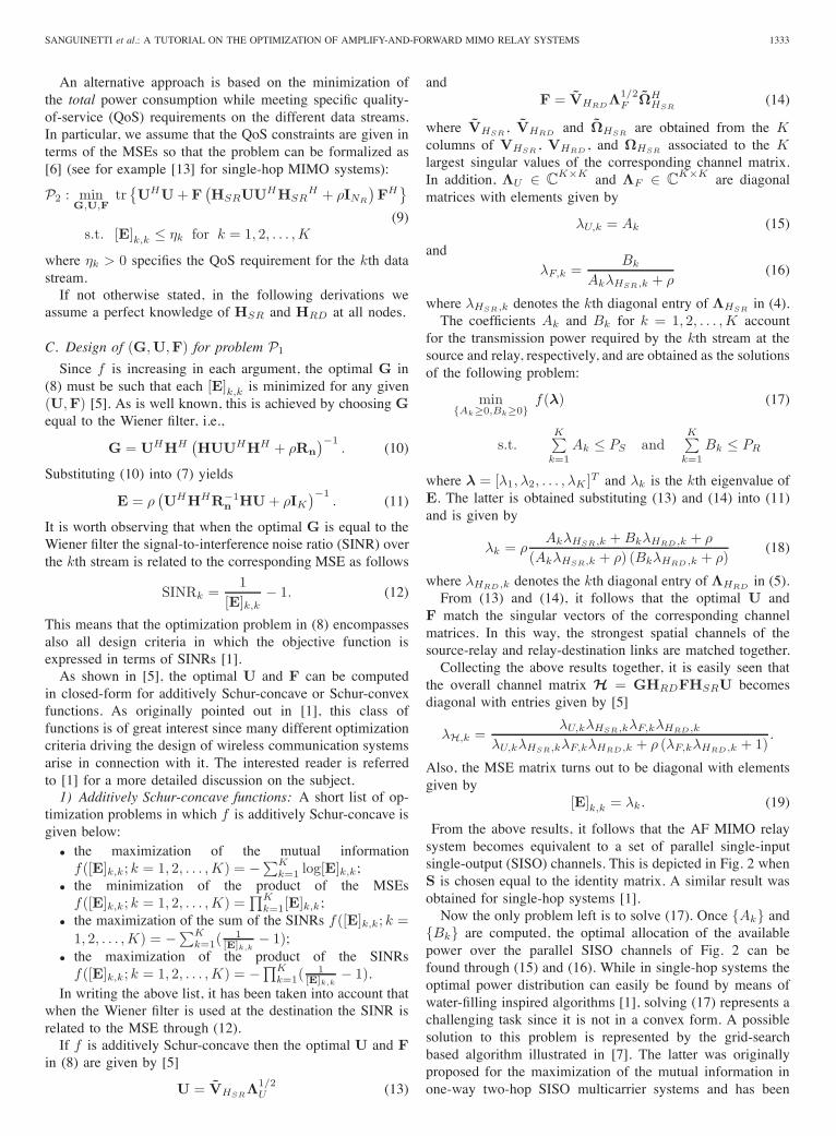
and then over all possible λk within the feasible set of (28).As shown in [12], this approach allows to approximate theoriginal problem with a convex one, whose solution can becomputed in closed-form through a multi-step procedure thatrequires no more than K − 1 steps.Fig. 4 illustrates the total power consumption in dB when
the noise variances over the source-relay and relay-destinationlinks are both equal to 0 dB, NS = NR = K = 3 while theQoS constraints are for simplicity assumed to be identical, i.e.,η1 = η2 = η3 = η. The curve labelled with GP refers to asystem in which the power allocation problem is approximatedusing the geometric programming approach proposed in [6]while RC corresponds to the reduced complexity algorithmdeveloped in [12]. Comparisons are made with SA (sub-optimal algorithm) in which the unitary matrix S in (25) is setequal to the identity matrix [6]. As seen, GP and RC providesubstantially the same performance and achieve a remarkablegain with respect to SA. In [12], it is shown that the solutionprovided by RC leads to a total power consumption that isvery close to the minimum.Remark. It is worth observing that in practical applica-
tions source and relay may be unable to meet all the QoSrequirements due to their limited power resource or due toregulations specifying the maximum transmit power. Thiscalls for some countermeasures. A possible way out to thisproblem (not investigated yet) is represented by the techniqueillustrated in [13] for single-hop MIMO systems in which the
1336 IEEE JOURNAL ON SELECTED AREAS IN COMMUNICATIONS, VOL. 30, NO. 8, SEPTEMBER 2012
��
��
��
��
��
��
�
�
Tot
al p
ower
con
sum
ptio
n, d
B
��� ��� �� �� ��� ��� ��� ��� ���
�
SA GP RC GP-DFE RC-DFE
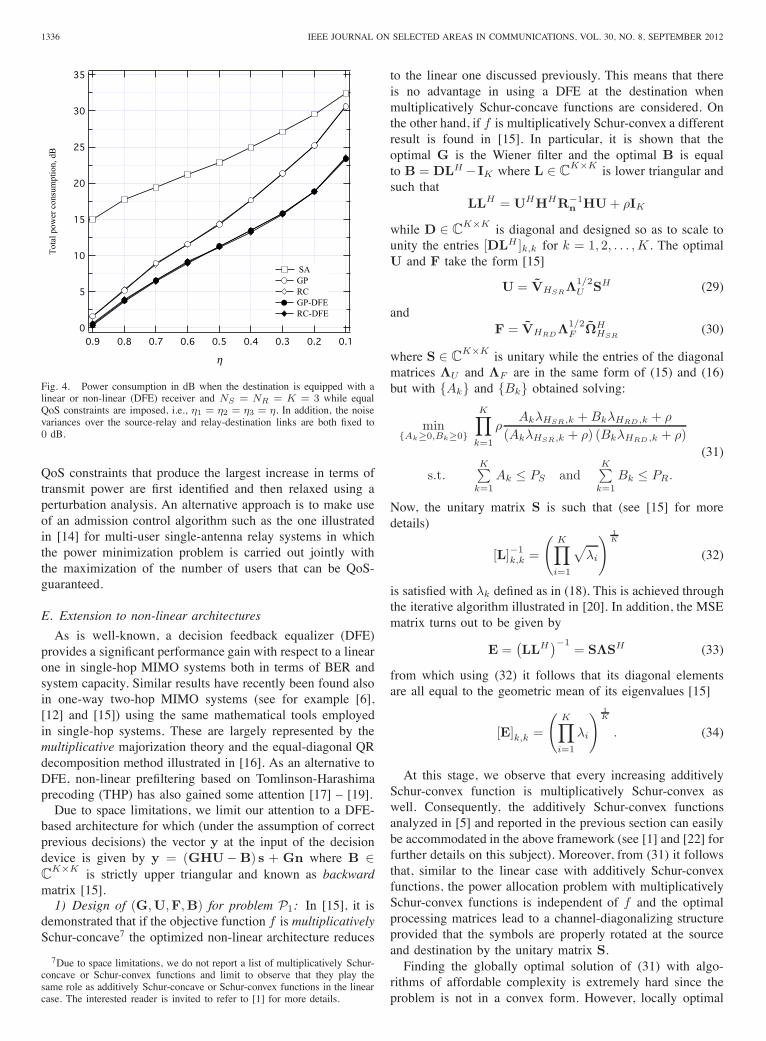
Fig. 4. Power consumption in dB when the destination is equipped with alinear or non-linear (DFE) receiver and NS = NR = K = 3 while equalQoS constraints are imposed, i.e., η1 = η2 = η3 = η. In addition, the noisevariances over the source-relay and relay-destination links are both fixed to0 dB.
QoS constraints that produce the largest increase in terms oftransmit power are first identified and then relaxed using aperturbation analysis. An alternative approach is to make useof an admission control algorithm such as the one illustratedin [14] for multi-user single-antenna relay systems in whichthe power minimization problem is carried out jointly withthe maximization of the number of users that can be QoS-guaranteed.
E. Extension to non-linear architectures
As is well-known, a decision feedback equalizer (DFE)provides a significant performance gain with respect to a linearone in single-hop MIMO systems both in terms of BER andsystem capacity. Similar results have recently been found alsoin one-way two-hop MIMO systems (see for example [6],[12] and [15]) using the same mathematical tools employedin single-hop systems. These are largely represented by themultiplicative majorization theory and the equal-diagonal QRdecomposition method illustrated in [16]. As an alternative toDFE, non-linear prefiltering based on Tomlinson-Harashimaprecoding (THP) has also gained some attention [17] – [19].Due to space limitations, we limit our attention to a DFE-
based architecture for which (under the assumption of correctprevious decisions) the vector y at the input of the decisiondevice is given by y = (GHU− B) s + Gn where B ∈C
K×K is strictly upper triangular and known as backwardmatrix [15].1) Design of (G,U,F,B) for problem P1: In [15], it is
demonstrated that if the objective function f is multiplicativelySchur-concave7 the optimized non-linear architecture reduces
7Due to space limitations, we do not report a list of multiplicatively Schur-concave or Schur-convex functions and limit to observe that they play thesame role as additively Schur-concave or Schur-convex functions in the linearcase. The interested reader is invited to refer to [1] for more details.
to the linear one discussed previously. This means that thereis no advantage in using a DFE at the destination whenmultiplicatively Schur-concave functions are considered. Onthe other hand, if f is multiplicatively Schur-convex a differentresult is found in [15]. In particular, it is shown that theoptimal G is the Wiener filter and the optimal B is equalto B = DLH − IK where L ∈ C
K×K is lower triangular andsuch that
LLH = UHHHR−1n HU + ρIK
while D ∈ CK×K is diagonal and designed so as to scale to
unity the entries [DLH ]k,k for k = 1, 2, . . . , K . The optimalU and F take the form [15]
U = VHSRΛ1/2U SH (29)
andF = VHRDΛ1/2
F ΩHHSR
(30)
where S ∈ CK×K is unitary while the entries of the diagonal
matrices ΛU and ΛF are in the same form of (15) and (16)but with {Ak} and {Bk} obtained solving:
min{Ak≥0,Bk≥0}
K∏k=1
ρAkλHSR,k + BkλHRD ,k + ρ
(AkλHSR,k + ρ) (BkλHRD ,k + ρ)(31)
s.t.K∑
k=1
Ak ≤ PS andK∑
k=1
Bk ≤ PR.
Now, the unitary matrix S is such that (see [15] for moredetails)
[L]−1k,k =
(K∏
i=1
√λi
) 1K
(32)
is satisfied with λk defined as in (18). This is achieved throughthe iterative algorithm illustrated in [20]. In addition, the MSEmatrix turns out to be given by
E =(LLH
)−1= SΛSH (33)
from which using (32) it follows that its diagonal elementsare all equal to the geometric mean of its eigenvalues [15]
[E]k,k =
(K∏
i=1
λi
) 1K
. (34)
At this stage, we observe that every increasing additivelySchur-convex function is multiplicatively Schur-convex aswell. Consequently, the additively Schur-convex functionsanalyzed in [5] and reported in the previous section can easilybe accommodated in the above framework (see [1] and [22] forfurther details on this subject). Moreover, from (31) it followsthat, similar to the linear case with additively Schur-convexfunctions, the power allocation problem with multiplicativelySchur-convex functions is independent of f and the optimalprocessing matrices lead to a channel-diagonalizing structureprovided that the symbols are properly rotated at the sourceand destination by the unitary matrix S.Finding the globally optimal solution of (31) with algo-
rithms of affordable complexity is extremely hard since theproblem is not in a convex form. However, locally optimal
SANGUINETTI et al.: A TUTORIAL ON THE OPTIMIZATION OF AMPLIFY-AND-FORWARD MIMO RELAY SYSTEMS 1337
solutions can be obtained resorting to the same methodsillustrated previously for the linear case [15].In Fig. 3, the curve labelled with “Max - MSE with DFE”
refers to a system in which the destination is equipped witha DFE and the design is made according to a multiplicativelySchur-convex function: the minimization of the maximumMSE. The available power is allocated using the alternatingalgorithm proposed in [5] and [9]. As expected, a non-linearsystem provides better performance than a linear one. Thisadvantage is lost if a multiplicatively Schur-concave functionis chosen since in these circumstances the non-linear systemreduces to the linear one.2) Design of (G,U,F,B) for problem P2: When the
power minimization problem is considered, in [6] it is shownthat the optimal (G,U,F,B) have the same form as beforefor the case of multiplicatively Schur-convex functions withthe only differences that S is such that [L]−1
k,k =√
ηk fork = 1, 2, . . . , K and the quantities {Ak} and {Bk} aresolutions of the following problem:
min{Ak ≥ 0},{Bk ≥ 0}
K∑k=1
Ak+K∑
k=1
Bk
(35)
s.t.j∏
k=1
λk ≤j∏
k=1
ηk for j = 1, 2, . . . , K
0 < λk ≤ λk+1 ≤ 1 k = 1, 2, . . . , K − 1.
Using the same arguments adopted for the linear case, in [6] anupper- and a lower-bound to the globally optimal solution ofthe above non-convex problem are computed. Alternatively,the reduced-complexity procedure developed in [12] can beused.In Fig. 4, the curves labelled with GP-DFE and RC-DFE
refer respectively to a system in which the successive GPapproach of [6] and the algorithm developed in [12] areemployed in conjunction with a DFE. As seen, both solutionsrequire substantially the same power and largely outperformthe corresponding ones obtained with a linear receiver for allthe investigated values of η.
F. Extension to frequency selective fading channels
As done in single-hop MIMO systems, the above opti-mization procedures can be extended to frequency-selectivefading channels using multicarrier transmissions. To see howthis comes about, assume for example that an orthogonalfrequency-divisionmultiplexing (OFDM) transmission schemewith N subcarriers is used and focus on the problem ofminimizing a global objective function under fixed powerconstraints (problem P1). As illustrated in [5] and [15], whencooperation among subcarriers is allowed, the optimizationproblem is formally equivalent to (8) both for the linearand non-linear architecture (clearly, in the latter case theoptimization has also to be done with respect to the backwardmatrix B, just as discussed in Section II.E). This means thatif f is additively (multiplicatively) Schur-concave or Schur-convex then the optimal processing matrices have the sameform as before for the linear (non-linear) flat-fading case. Asimilar result holds true for the minimization of the total powerconsumption (problem P2).
Consider now the less general case in which an independentlinear processing has to be performed at each subcarrier. De-noting by Gn,Un and Fn the processing matrices operatingover the nth subcarrier and callingMSEn,k the MSE of the kthsymbol over the nth subcarrier, the optimization problem canbe formalized in (36), where f : R
N → R and fn : RK → R
are generic objective functions while HSR,n ∈ CNR×NS de-
notes the source-relay channel matrix over the nth subcarrier.Interestingly, if f and fn are increasing in each argument, theabove optimization problem can be greatly simplified using theprimal decomposition technique which allows to decomposethe given problem into N independent subproblems controlledby a master problem. The latter is given by
min{PS,n≥0},{PR,n≥0}
f({PS,n}, {PR,n})(37)
s.t.N∑
n=1PS,n ≤ PS and
N∑n=1
PR,n ≤ PR
where PS,n and PR,n denote the power allocated over thenth subcarrier by the source and relay, respectively, whilef({PS,n}, {PR,n}) = f(g1, g2, . . . , gN ) with each gn corre-sponding to the minimum value of the cost function fn in thefollowing subproblem:
minGn,Un,Fn
gn = fn(MSEn,1, MSEn,2, . . . , MSEn,K)
(38)s.t. tr{UnUH
n } ≤ PS,n
tr{Fn
(HSR,nUnUH
n HSR,nH + ρINR
)FH
n
} ≤ PR,n.
Using the above procedure, the solution of (36) can be effi-ciently computed as follows. The master problem in (37) canbe solved using the same techniques illustrated and analyzedin [21] while the nth subproblem turns out to have the sameform of (8) once f is replaced with fn. This means that whenfn is additively Schur-concave or Schur-convex8 the solutionof each subproblem can be computed in closed form as shownpreviously for the linear flat-fading case. Such a scheme isknown in the technical literature as carrier-noncooperative ap-proach with optimal power allocation [22]. Alternatively, thedesign of the processing matrices can be performed under theassumption that no-cooperation is allowed and a fixed power(for example, a uniform distributed power) is allocated to eachsubcarrier. This scheme is simply referred to as a carrier-noncooperative approach and it is again formally equivalentto (8). As expected, the carrier-cooperative approach performsbetter than the carrier-noncooperative ones especially whenhighly frequency selective channels are considered [5]. Indeed,in these circumstances the frequency diversity of the channelprovides additional degrees of freedom that with cooperatingsubcarriers can be exploited to improve the system perfor-mance.The problem of minimizing the total power consumption in
OFDM-MIMO systems in which several types of services aresupported through spatial multiplexing has recently been in-vestigated in [23]. Since in practical applications the reliabilityof each type of transmission depends on a global performance
8Observe that in the carrier cooperative scheme the global cost function fis required to be additively Schur-concave/convex, whereas in the noncoop-erative scheme each fn must be additively Schur-concave/ convex.
1338 IEEE JOURNAL ON SELECTED AREAS IN COMMUNICATIONS, VOL. 30, NO. 8, SEPTEMBER 2012
minGn,Un,Fn
f(g1, g2, . . . , gN ) (36)
s.t. gn = fn(MSEn,1, MSEn,2, . . . , MSEn,K) n = 1, 2, . . . , NN∑
n=1tr{UnUH
n } ≤ PS
N∑n=1
tr{Fn
(HSR,nUnUH
n HSR,nH + ρINR
)FH
n
} ≤ PR
metric measured over the assigned subcarriers, differentlyfrom [6] the power minimization problem is reformulatedassuming that the QoS constraint of each service is givenas a generic Schur-convex function of the MSEs over allsubcarriers rather than as a set of constraints on individualMSEs. Interestingly, it turns out that the solution of thisproblem reduces to the one illustrated in [6] for both a linearand a non-linear architecture. The only difference with respectto [6] relies on the structure of the unitary matrix to applyto the transmitted data symbols at the source and destinationnodes.
G. Acquisition of channel state information and robust opti-mization
As seen, the optimization of a one-way two-hop MIMOsystem requires explicit knowledge of the source-relay andrelay-destination channel matrices. In principle, channel ac-quisition at the receiver (relay and destination) can be obtainedusing the same methods employed in conventional single-hopMIMO networks (see for example [24] and references therein).Specific algorithms for channel estimation in AF relay systemsare also available in literature. For example, the estimation ofboth the source-relay and relay-destination channels can beperformed directly at the destination node through the pilot-based schemes recently proposed in [25] and [26]. On theother hand, channel acquisition at the transmitter (source andrelay) is a more demanding task. A possible solution leadingto open-loop architectures relies on exploiting the channelreciprocity between the forward and reverse links, and it issuited for systems operating in time-division duplexing (TDD)mode. Unfortunately, the reciprocity is only valid for the “overthe air” (i.e., from antenna to antenna) segment while channelestimation is usually performed at the baseband level afterthe radio-frequency chain. This calls for efficient calibrationschemes not easy to be implemented [27]. An alternative ap-proach suited for both TDD and frequency-division duplexing(FDD) modes consists in performing the estimation process atthe receiver and feeding channel measurements back through areliable reverse link. This strategy leads to closed-loop systemsand it is nowadays considered as the most promising solutionfor commercial applications.Motivated by the above discussion, we focus on closed-
loop techniques in the next. This amounts to saying that theestimation of HSR is performed at the relay whereas thetask of estimating HRD is left to the destination node. Onceestimates of HSR and HRD are available, one has to decidehow they should be shared among the nodes for the compu-tation of the optimal processing matrices. A possible solution
is to make use of a distributed9 algorithm in which eachnode computes its own processing matrix. This means that theestimates ofHSR andHRD must be sent from the relay to thedestination and from the destination to the relay, respectively,whereas they must be both transmitted to the source node viaa feedback channel from the relay. An alternative approach isrepresented by a centralized algorithm in which only a singlenode computes all the optimal processing matrices and thentransmits them to the others. Clearly, the centralized strategyrequires the computation node to acquire information aboutall the propagation channels either by direct estimation or viafeedback links.Remark: As mentioned in the Introduction, this work is
mainly focused on transceiver design under the assumptionthat source and relay have perfect or at least partial knowl-edge of the propagation channel. As is well-known, whenthis assumption does not hold true and no channel stateinformation is available during transmission, one may resortto space-time coding techniques as a means to significantlyimprove the link reliability and spectral efficiency of wirelesscommunication systems. Since the pioneering work of Tarokhet al. in [28], space-time coding has gained a lot of interestboth from academia and industry, and a large number ofpublications has flourished in the literature in a few years(see [29] and references therein). Most of the research activityhas primarily been focused on single-hop MIMO systems butit has recently been extended to relay networks with singleor multiple antennas under the name of cooperative diversityor user diversity (see for example [30]). Herein, the multipleterminals (source and/or relays) cooperate to create a virtualantenna array that provides some form of spatial diversity. Dueto space limitations, we cannot provide a detailed descriptionof the possible architectures but we refer the interested readerto [31] – [40] (and references therein) for a comprehensiveoverview of the literature available on this subject.1) Robust Linear Optimization: Assume that estimates
HSR and HRD of the source-relay and relay-destination chan-nels are available. The simplest solution is to use them in placeofHSR andHRD for the computation of the optimal process-ing matrices. Although simple, such an approach leads to asubstantial performance degradation with respect to the perfectknowledge case. An alternative route consists in designingthe optimal matrices taking the channel estimation errors intoaccount. This leads to the so-called robust optimization designin which either min-max approaches or stochastic methodsare usually employed [41]. In the sequel, we concentrate on
9The word “distributed” has several meanings in wireless communicationsbut herein it is used to refer to a system in which each node makes only useof the channel state information available locally.
SANGUINETTI et al.: A TUTORIAL ON THE OPTIMIZATION OF AMPLIFY-AND-FORWARD MIMO RELAY SYSTEMS 1339
H1 H2 Hi HLHi+1 yF0...
x0
Ns
1
F1 x1r1NsNs
1 1
F2 x2r2
NsNs
1 1
Fi xiri
NsNs
1 1s
GNs
1rL
.
.
....
.
.
....
.
.
....
.
.
.
Fig. 5. Block diagram of one-way multi-hop MIMO systems.
stochastic methods and review some recent works developedspecifically for a linear AF architecture.The robust design of (G,F) that minimizes the sum of the
MSEs with a power constraint at the relay has been addressedin [42]. The main difference with respect to the perfect channelknowledge case is that all the statistical expectations involvedin the optimization problem are computed also with respect tothe distribution of the channel estimation errors. To this end,in [42] the following error models are assumed (see also [43]and [44] and references therein):
HSR = HSR + ΔSR (39)
andHRD = HRD + ΔRD (40)
whereΔSR = Σ1/2
SRΔ(w)SRΨ1/2
SR (41)
andΔRD = Σ1/2
RDΔ(w)RDΨ1/2
RD (42)
are the channel estimation error matrices. In particular, theelements of Δ(w)
SR ∈ CNR×NS(Δ(w)
RD ∈ CNS×NR)are
independent and identically distributed zero-mean complexGaussian random variables with unit variance, while ΣSR ∈CNR×NR
(ΣRD ∈ CNS×NS
)and ΨT
SR ∈ CNS×NS(ΨT
RD ∈CNR×NR
)are the row and column covariance matrices of
ΔSR (ΔRD), respectively. Assuming that the covariancematrices are perfectly known and that HSR and HRD aregiven, the channel uncertainties in (39) and (40) are onlyrepresented by Δ(w)
SR and Δ(w)RD in (41) and (42). In these
circumstances, it is easily recognized that the a posterioridistributions of the matrices HSR and HRD in (39) and (40)follow the well-known Gaussian-Kronecker model [42].It is worth observing that the expressions of ΣSR, ΨSR,
ΣRD and ΨRD depend on the specific channel estimationalgorithm. For example, it can easily be shown [42, Remark1] that the above model includes two well-known BayesianMMSE estimators proposed in literature [43] –[44].The robust design of (G,U,F) has been addressed in
[45] for a flat-fading scenario and in [46] for an OFDMsystem operating over a frequency-selective fading channel.The extension of these results to additively Schur-concave andSchur-convex functions can be found in [47] and is now brieflyreviewed.We start observing that the optimization problem in (8),
when all nodes have imperfect channel state information, takesthe following form [47]:
P1 : minG,U,F
f([
E]k,k
; k = 1, 2, . . . , K)
(43)s.t. tr
{UUH
} ≤ PS
tr{F(HSRUUHHH
SR + αΣSR + ρINR
)FH}≤ PR
where α = tr{UUHΨSR} and E = EHSR,HRD{E} denotesthe expectation of the MSE matrix in (7) computed withrespect to the statistical distributions of HSR and HRD in(39) and (40). This yields
E = GAGH − GHU − UHHHGH + IK
where we have defined H = HRDFHSR and A (top of thefollowing page) with
β = tr{F(HSRUUHHHSR + αΣSR + ρINR)FHΨRD}.
The optimal G in (43) is the Wiener filter given by G =UHHHA−1. On the other hand, finding the optimal U andF for arbitrary covariance matrices is very difficult. In [47]their explicit structure is provided only when the row and/orthe column covariance matrices are equal to scaled identitymatrices. For example, assume that ΣSR = εSRINR andΣRD = εRDINS and let the SVDs of HSR and HRD berespectively given by
HSR = ΩHSRΛ1/2
HSRVH
HSR
and
HRD = ΩHRDΛ1/2
HRDVH
HRD.
In the above circumstances, if additively Schur-concave func-tions are considered the optimal U and F take the form [47]
U = VHSRΛ1/2
U (44)
and
F = VHRDΛ1/2
F ΩHHSR
(45)
where ΩHSR, VHSR
and VHRDcorrespond to theK columns
of ΩHSR,VHSR
andVHRDassociated to theK largest singu-
lar values. The entries of the diagonal matrices ΛU ∈ CK×K
and ΛF ∈ CK×K can be obtained through the iterative
method developed in [5]. If f is a Schur-convex function, theoptimal F is as in (45) while the optimal U is given by
U = VHSRΛ1/2
U SH (46)
with S being a proper unitary matrix chosen such that thediagonal elements of E are all equal to the arithmetic meanof its eigenvalues.As mentioned before, in [42] and [45] – [47] it is shown that
a robust design provides better performance compared to thesimple scheme in which the channel estimation errors are nottaken into account and the estimated channel matrices HSR
and HRD are simply used in place of HSR and HRD.
1340 IEEE JOURNAL ON SELECTED AREAS IN COMMUNICATIONS, VOL. 30, NO. 8, SEPTEMBER 2012
A = βHRDF(HSRUUHHH
SR + αΣSR + ρINR
)FHHH
RDΣRD + INS
III. OPTIMIZATION OF A ONE-WAY MULTI-HOP MIMOSYSTEM
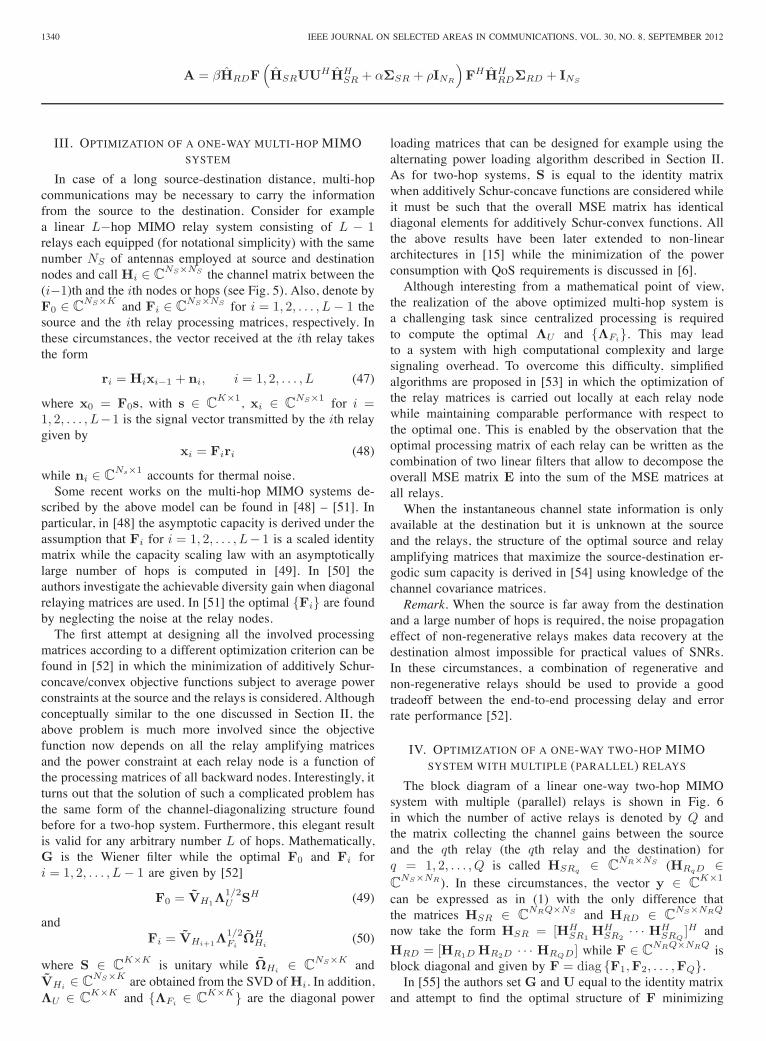
In case of a long source-destination distance, multi-hopcommunications may be necessary to carry the informationfrom the source to the destination. Consider for examplea linear L−hop MIMO relay system consisting of L − 1relays each equipped (for notational simplicity) with the samenumber NS of antennas employed at source and destinationnodes and call Hi ∈ C
NS×NS the channel matrix between the(i−1)th and the ith nodes or hops (see Fig. 5). Also, denote byF0 ∈ C
NS×K and Fi ∈ CNS×NS for i = 1, 2, . . . , L − 1 the
source and the ith relay processing matrices, respectively. Inthese circumstances, the vector received at the ith relay takesthe form
ri = Hixi−1 + ni, i = 1, 2, . . . , L (47)
where x0 = F0s, with s ∈ CK×1, xi ∈ C
NS×1 for i =1, 2, . . . , L−1 is the signal vector transmitted by the ith relaygiven by
xi = Firi (48)
while ni ∈ CNs×1 accounts for thermal noise.
Some recent works on the multi-hop MIMO systems de-scribed by the above model can be found in [48] – [51]. Inparticular, in [48] the asymptotic capacity is derived under theassumption that Fi for i = 1, 2, . . . , L− 1 is a scaled identitymatrix while the capacity scaling law with an asymptoticallylarge number of hops is computed in [49]. In [50] theauthors investigate the achievable diversity gain when diagonalrelaying matrices are used. In [51] the optimal {Fi} are foundby neglecting the noise at the relay nodes.The first attempt at designing all the involved processing
matrices according to a different optimization criterion can befound in [52] in which the minimization of additively Schur-concave/convex objective functions subject to average powerconstraints at the source and the relays is considered. Althoughconceptually similar to the one discussed in Section II, theabove problem is much more involved since the objectivefunction now depends on all the relay amplifying matricesand the power constraint at each relay node is a function ofthe processing matrices of all backward nodes. Interestingly, itturns out that the solution of such a complicated problem hasthe same form of the channel-diagonalizing structure foundbefore for a two-hop system. Furthermore, this elegant resultis valid for any arbitrary number L of hops. Mathematically,G is the Wiener filter while the optimal F0 and Fi fori = 1, 2, . . . , L − 1 are given by [52]
F0 = VH1Λ1/2U SH (49)
andFi = VHi+1Λ
1/2Fi
ΩHHi
(50)
where S ∈ CK×K is unitary while ΩHi ∈ C
NS×K andVHi ∈ C
NS×K are obtained from the SVD ofHi. In addition,ΛU ∈ C
K×K and {ΛFi ∈ CK×K} are the diagonal power
loading matrices that can be designed for example using thealternating power loading algorithm described in Section II.As for two-hop systems, S is equal to the identity matrixwhen additively Schur-concave functions are considered whileit must be such that the overall MSE matrix has identicaldiagonal elements for additively Schur-convex functions. Allthe above results have been later extended to non-lineararchitectures in [15] while the minimization of the powerconsumption with QoS requirements is discussed in [6].Although interesting from a mathematical point of view,
the realization of the above optimized multi-hop system isa challenging task since centralized processing is requiredto compute the optimal ΛU and {ΛFi}. This may leadto a system with high computational complexity and largesignaling overhead. To overcome this difficulty, simplifiedalgorithms are proposed in [53] in which the optimization ofthe relay matrices is carried out locally at each relay nodewhile maintaining comparable performance with respect tothe optimal one. This is enabled by the observation that theoptimal processing matrix of each relay can be written as thecombination of two linear filters that allow to decompose theoverall MSE matrix E into the sum of the MSE matrices atall relays.When the instantaneous channel state information is only
available at the destination but it is unknown at the sourceand the relays, the structure of the optimal source and relayamplifying matrices that maximize the source-destination er-godic sum capacity is derived in [54] using knowledge of thechannel covariance matrices.Remark. When the source is far away from the destination
and a large number of hops is required, the noise propagationeffect of non-regenerative relays makes data recovery at thedestination almost impossible for practical values of SNRs.In these circumstances, a combination of regenerative andnon-regenerative relays should be used to provide a goodtradeoff between the end-to-end processing delay and errorrate performance [52].
IV. OPTIMIZATION OF A ONE-WAY TWO-HOP MIMOSYSTEM WITH MULTIPLE (PARALLEL) RELAYS
The block diagram of a linear one-way two-hop MIMOsystem with multiple (parallel) relays is shown in Fig. 6in which the number of active relays is denoted by Q andthe matrix collecting the channel gains between the sourceand the qth relay (the qth relay and the destination) forq = 1, 2, . . . , Q is called HSRq ∈ C
NR×NS (HRqD ∈C
NS×NR). In these circumstances, the vector y ∈ CK×1
can be expressed as in (1) with the only difference thatthe matrices HSR ∈ C
NRQ×NS and HRD ∈ CNS×NRQ
now take the form HSR = [HHSR1
HHSR2
· · · HHSRQ
]H and
HRD = [HR1D HR2D · · · HRQD] while F ∈ CNRQ×NRQ is
block diagonal and given by F = diag {F1,F2, . . . ,FQ}.In [55] the authors set G and U equal to the identity matrix
and attempt to find the optimal structure of F minimizing
SANGUINETTI et al.: A TUTORIAL ON THE OPTIMIZATION OF AMPLIFY-AND-FORWARD MIMO RELAY SYSTEMS 1341
U... G
...s
1
NS
1
NS
F1...
...
1
NR
1
NR
y
HSR
HR D
Fir
st p
hase
Second phase
F2...
...
1
NR
1
NR
HSR
HR D
Fir
st p
hase
Second phase
FQ...
...
1
NR
1
NR
HR
DSe
cond
pha
seHSR
First phase
.
.
.
12
Q
Q
21
Fig. 6. Block diagram of one-way two-hop linear MIMO systems withmultiple relays.
the sum of the MSEs subject to a global power constraintat the output of the relays. Unfortunately, the solution isfound in closed-form only for the simple case in which relaysare equipped with a single antenna, i.e., NR = 1 whilethe multiple antenna case is addressed without imposing anypower constraint at the relays. The design of F that minimizesthe total power consumption while fulfilling a given set ofSNR constraints is investigated in [56] and a power efficientsolution is derived in closed-form after solving a two-stepoptimization problem. The extension to a system in whichU and G may have a general structure has recently beenconsidered in [57] for the minimization of the sum of theMSEs. In particular, in [57] it is found that the optimal G isthe Wiener filter while the optimal U and F are such that
U = VHSRΛ1/2U (51)
and
HRDF = PΛ1/2F ΩH
HSR. (52)
In the above equations, P ∈ CK×K is an arbitrary unitary
matrix while ΩHSR ∈ CQNR×K and VHSR ∈ C
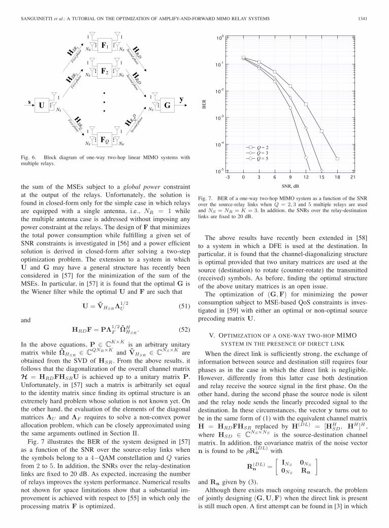
NS×K areobtained from the SVD of HSR. From the above results, itfollows that the diagonalization of the overall channel matrixH = HRDFHSRU is achieved up to a unitary matrix P.Unfortunately, in [57] such a matrix is arbitrarily set equalto the identity matrix since finding its optimal structure is anextremely hard problem whose solution is not known yet. Onthe other hand, the evaluation of the elements of the diagonalmatrices ΛU and ΛF requires to solve a non-convex powerallocation problem, which can be closely approximated usingthe same arguments outlined in Section II.Fig. 7 illustrates the BER of the system designed in [57]
as a function of the SNR over the source-relay links whenthe symbols belong to a 4−QAM constellation and Q variesfrom 2 to 5. In addition, the SNRs over the relay-destinationlinks are fixed to 20 dB. As expected, increasing the numberof relays improves the system performance. Numerical resultsnot shown for space limitations show that a substantial im-provement is achieved with respect to [55] in which only theprocessing matrix F is optimized.
����
����
����
����
����
���
BE
R
������������
SNR, dB
Q = 2 Q = 3 Q = 5
Fig. 7. BER of a one-way two-hop MIMO system as a function of the SNRover the source-relay links when Q = 2, 3 and 5 multiple relays are usedand NS = NR = K = 3. In addition, the SNRs over the relay-destinationlinks are fixed to 20 dB.
The above results have recently been extended in [58]to a system in which a DFE is used at the destination. Inparticular, it is found that the channel-diagonalizing structureis optimal provided that two unitary matrices are used at thesource (destination) to rotate (counter-rotate) the transmitted(received) symbols. As before, finding the optimal structureof the above unitary matrices is an open issue.The optimization of (G,F) for minimizing the power
consumption subject to MSE-based QoS constraints is inves-tigated in [59] with either an optimal or non-optimal sourceprecoding matrix U.
V. OPTIMIZATION OF A ONE-WAY TWO-HOP MIMOSYSTEM IN THE PRESENCE OF DIRECT LINK
When the direct link is sufficiently strong, the exchange ofinformation between source and destination still requires fourphases as in the case in which the direct link is negligible.However, differently from this latter case both destinationand relay receive the source signal in the first phase. On theother hand, during the second phase the source node is silentand the relay node sends the linearly precoded signal to thedestination. In these circumstances, the vector y turns out tobe in the same form of (1) with the equivalent channel matrixH = HRDFHSR replaced by H(DL) = [HH
SD, HH ]H ,where HSD ∈ C
NS×NS is the source-destination channelmatrix. In addition, the covariance matrix of the noise vectorn is found to be ρR(DL)
n with
R(DL)n =
[INS 0NS
0NS Rn
]and Rn given by (3).Although there exists much ongoing research, the problem
of jointly designing (G,U,F) when the direct link is presentis still much open. A first attempt can be found in [3] in which
1342 IEEE JOURNAL ON SELECTED AREAS IN COMMUNICATIONS, VOL. 30, NO. 8, SEPTEMBER 2012
the maximization of the mutual information is considered andthe design of F is carried out under the assumption that nooperation is performed at the source and destination. Thisamounts to setting G and U equal to the identity matrix.Unfortunately, finding the solution of the above problem turnsout to be extremely challenging and only upper- and lower-bounds of the mutual information are used to compute F.The same problem is considered in [4] wherein a suboptimalstructure of F is derived following a different line, which doesnot take the power constraint at the relay into account. In [60],U is chosen equal to the identity matrix and the joint designof (G,F) is based on the following optimization problem
minG,F
f([E]k,k ; k = 1, 2, . . . , K
)(53)
s.t. tr{F(HSRHH
SR + ρINR
)FH} ≤ PR
where f is a generic increasing function of its arguments. Asshown in [60], the optimal G is again the Wiener filter whilethe relay processing matrix F is found solving (53) with Enow given by
E = ρ(HH
SDHSD + HHR−1n H + ρIK
)−1.
From the right-hand-side of the above equation, it is seen thatdifferently from (11) an additional termHH
SDHSD accountingfor the direct link is present in the MSE matrix. The optimalF in (53) has the following form [60]
F = VHRDAΩHHSR
where A ∈ CK×K . The above result indicates that F is
a general linear beamforming matrix matched to the left(right) singular vectors of the source-relay (relay-destination)channel. The only difference with respect to the case in whichthe direct link is neglected is that A is not diagonal unlike ΛF
in (14). This means that the optimized structure does not leadto a diagonalization of the overall communication system. In[60] a closed form solution for the optimalA is provided onlyfor the simple case in which a single antenna is employedat the source. On the other hand, when multiple antennasare employed A is optimized only by means of numericalmethods.In [61] the authors deal with the problem of designing
(G,U,F) so as to minimize the sum of the MSEs subjectto power constraints at the source and relay. As expected, theoptimal G is found to be the Wiener filter while the jointdesign of U and F is addressed by means of a suboptimaltwo-stage procedure not based on any optimality criterion. Thesame problem is addressed in [10] where it is shown that theoptimal F has the following structure:
F = VHRDAΩH
where A ∈ CK×K while Ω ∈ C
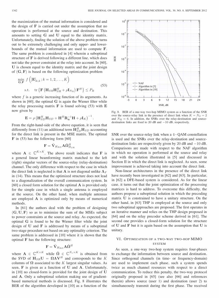
Ns×K is obtained fromthe SVD of HSRU = ΩΛVH and corresponds to the Kcolumns of Ω associated to the K largest singular values. Asseen, F is given as a function of U and A. Unfortunately,in [10] no closed-form is provided for the joint design of Uand A. Only a suboptimal solution making use of gradient-based numerical methods is discussed. Fig. 8 illustrates theBER of the algorithm developed in [10] as a function of the
����
����
����
����
����
����
���
BE
R
��������������
SNR, dB
NAF Algorithm in [5] Algorithm in [10]
Fig. 8. BER of a one-way two-hop MIMO system as a function of the SNRover the source-relay link in the presence of direct link when K = NS = 2and NR = 6. In addition, the SNRs over the relay-destination and source-destination links are fixed to 20 dB and −10 dB, respectively.
SNR over the source-relay link when a 4−QAM constellationis used and the SNRs over the relay-destination and source-destination links are respectively given by 20 dB and −10 dB.Comparisons are made with respect to the NAF algorithmin which no operation is performed at the source and relayand with the solution illustrated in [5] and discussed inSection II in which the direct link is neglected. As seen, someimprovement is achieved taking into account the direct link.Non-linear architectures in the presence of the direct link
have recently been investigated in [62] and [63]. In particular,in [62] a DFE-based system is considered. As for the linearcase, it turns out that the joint optimization of the processingmatrices is hard to address. To overcome this difficulty, theauthors propose a suboptimal solution in which the precodingmatrix U is constrained to have a unitary structure. On theother hand, in [63] THP is employed at the source and onlytwo suboptimal approaches are proposed. The first operates inan iterative manner and relies on the THP design proposed in[64] and on the relay precoder scheme derived in [61]. Thesecond one provides a closed-form solution for the structureof U and F but it is again based on the assumption that U isunitary.
VI. OPTIMIZATION OF A TWO-WAY TWO-HOP MIMOSYSTEM
As seen, a one-way two-hop system requires four-phasesto exchange the information between source and destination.Since orthogonal channels (in time- or frequency-domain)are used to implement each phase, such a system spendstwice as much channel resources with respect to a directcommunication. To reduce this penalty, the two-way protocoloriginally proposed in [65] (see also [66] and referencestherein) allows source (user 1) and destination (user 2) tosimultaneously transmit during the first phase. The received
SANGUINETTI et al.: A TUTORIAL ON THE OPTIMIZATION OF AMPLIFY-AND-FORWARD MIMO RELAY SYSTEMS 1343
information at the relays is then forwarded to user 1 and 2in the second phase. Since both user 1 and user 2 know theirown transmitted data, they can remove the self-interferencefrom the received signal provided that the required channelstate information is available. This leads to a scheme with thesame spectral efficiency of direct communications and at thesame time able to take advantage of the potential benefits ofrelay communications.The block diagram of a two-way two-hop MIMO relay
network is shown in Fig. 9 in which si for i = 1, 2 is used todenote the symbol vector transmitted by the ith user. In thesecircumstances, the signal received at the relay during the firstphase can be expressed as
yR = H1RUs1 + H2RGs2 + nR
where HiR ∈ CNR×NS for i = 1, 2 denotes the channel
matrix from the ith user to the relay while nR accounts forthermal noise with zero mean and covariance matrix given byρINR . At the relay, the vector yR is first processed by a matrixF ∈ C
NR×NR and then forwarded to both users during thesecond phase. The received vector yi for i = 1, 2 takes theform
y1 = HR1FH2RGs2︸ ︷︷ ︸useful signal
+HR1FH1RUs1︸ ︷︷ ︸self-interference
+HR1FnR + n1︸ ︷︷ ︸noise contribution
(54)and
y2 = HR2FH1RUs1︸ ︷︷ ︸useful signal
+HR2FH2RGs2︸ ︷︷ ︸self-interference
+HR2FnR + n2︸ ︷︷ ︸noise contribution
(55)where HRi ∈ C
NS×NR for i = 1, 2 denotes the channelmatrix from the relay to the ith user and ni for i = 1, 2is Gaussian with zero mean and covariance matrix ρINS .As explained earlier, from (54) it is seen that if user 1 hasknowledge of HR1FH1R it may remove its self-interferenceterm from the received signal. The same can be done by user2 if HR2FH2R is known. Then, the vectors at the input ofthe decision devices are given by z1 = H′
1Gs2 + n′1 and
z2 = H′2Us1 + n′
2 where we have defined H′1 = HR1FH2R
and H′2 = HR2FH1R while n′
1 and n′2 are respectively given
by n′1 = HR1FnR + n1 and n′
2 = HR2FnR + n2.Some recent works on two-way two-hop MIMO relay
networks can be found in [67] and [68] (see also [69] andreferences therein). In particular, in [67] the authors concen-trate either on the maximization of the achievable sum rate oron the minimization of the sum of the MSEs while imposingpower constraints at the terminals and relay. In both cases,they develop an iterative algorithm based on the gradientdescendent technique that allows to numerically compute anapproximation of the optimal (G,U,F) (even for the case inwhich multiple relays are used). On the other hand, in [68]the authors deal only with the maximization of the achievablesum rate and demonstrate that when NR ≥ 2NS the optimalF takes the form
F = Q1AQH2 (56)
where A ∈ C2NS×2NS is an arbitrary matrix while
(Q1,Q2) ∈ CNR×2NS are semi-unitary matrices obtained
from the following two QR decompositions:[HH
R1 HHR2
]= Q1R1
and[H1R H2R] = Q2R2
with (R1,R2) ∈ C2NS×2NS being upper triangular. On
the basis of the above result, it follows that the originalproblem reduces to jointly design (G,U,A). Clearly, thisdoes not change the nature of the problem but it has the onlypractical relevance to lead to a simplification of the problemin those applications for which NR > 2NS . Unfortunately, in[68] it is shown that the optimal structure of the processingmatrices (G,U,A) is hard to find in closed-form since theoptimization problem is not convex. This is in sharp contrastto the one-way relay systems discussed in Section II in whichthe optimal structure of (G,U,F) are found in closed-formand leads to the diagonalization of the entire relay system.To overcome this difficulty, a couple of numerical methodsbased on iterative procedures in which A and (G,U) arealternatively optimized are proposed in [68]. In particular,the optimization of A for a given set of matrices (G,U)is performed by means of two different algorithms. The firstone is a hybrid algorithm in which the gradient descendentsearch and the Newton’s method are adaptively combinedwhile the second one is inspired by the weighted minimumMSE algorithm originally proposed in [70]. On the other hand,the optimization of (G,U) for a given A requires to solvea convex problem whose solution is found by means of thegeneralized waterfilling algorithm developed in [71].From the above discussion, it follows that channel knowl-
edge in two-way relay systems plays a key role since it isnot only necessary for the design of the processing matricesbut also for self-cancellation purposes. Although the problemof channel estimation in one-way relay systems has gainedsome interest, little work has been done for the two-wayrelay protocol. The problem has been recently investigated in[72] in which a two-phase training-based algorithm is derivedaccording to two different criteria. The first one relies onthe maximum-likelihood methodology while the second oneis derived so as to maximize the SNR at the receiver aftertaking the channel estimation errors into account. A possibledrawback of these schemes is that they do not perform channelestimation at the relay in which only a scaling operationis performed. This means that the required channel stateinformation can be provided at the relay only via a feedbackchannel. A different approach is illustrated in [73] in whichchannel estimation is performed at the relay during the firstphase and it is then used in the second one to properly allocatethe power so as to improve the channel estimate quality atthe terminal nodes. An alternative approach using the parallelfactor analysis is proposed in [74].
VII. EXTENSIONS AND FUTURE LINES OF RESEARCH
This tutorial has discussed the optimization of AF MIMOrelay systems. A number of key architectures has been re-viewed and investigated under different design criteria andoperating conditions. As seen, the optimization of a one-way two-hop MIMO system is a well-understood issue when
1344 IEEE JOURNAL ON SELECTED AREAS IN COMMUNICATIONS, VOL. 30, NO. 8, SEPTEMBER 2012
U... G
...s1
1
NS
1
NS
F...
...
1
NR
1
NRH1R
First p
hase
HR1
Second phase
H2RFirst phaseH
R2Second phase
s2
Fig. 9. Block diagram of two-way two-hop linear MIMO systems.
perfect knowledge of the channel matrices is assumed. Muchwork has still to be done for the development of robustsolutions able to cope with channel uncertanties. On the otherhand, different aspects in the optimization of other architec-tures remain unsolved and/or to be further investigated. Aninteresting problem common to all the systems considered inthis tutorial is the deployment of decentralized algorithms thatmay provide a good tradeoff between performance and systemscalability. In addition to all this, there are still many exten-sions and future lines of research related to the optimization ofMIMO relay networks, some of which are briefly described inthe next. For example, the optimization of multiuser MIMOrelay systems has only recently become an active researchtopic. In particular, the multiaccess MIMO relay networks areaddressed in [53] – [54] while the multiuser broadcasting relaysystems are investigated in [71]. Compared to its single-usercounterpart, the optimization of a multiuser system is muchmore challenging due to the considerable amount of requiredchannel state information and computational complexity. An-other interesting direction is the interference MIMO relaynetwork where multiple source nodes communicate with theirdesired destination nodes with the aid of (distributed) relaynodes [14] and [75]. Due to the existence of interference, across layer design between the MAC layer and the PHY layermay be employed to optimize the overall system performance.Also, the optimization of full-duplex relay networks in whichloop-back interference is traded for higher spectral efficiencyis worthy of further investigation [76].
REFERENCES
[1] D. P. Palomar and Y. Jiang, MIMO Transceiver Design via MajorizationTheory. Now Publishers, vol. 3, no. 4 – 5, pp. 331 – 551: Foundationsand Trends in Commun. and Inf. Theory, 2006.
[2] G. Kramer, M. Gastpar, and P. Gupta, “Cooperative strategies andcapacity theorems for relay networks,” IEEE Trans. Inf. Theory, vol. 51,no. 9, pp. 3037 – 3063, Sept. 2005.
[3] X. Tang and Y. Hua, “Optimal design of non-regenerative MIMOwireless relays,” IEEE Trans. Wireless Commun., vol. 6, no. 4, pp. 1398–1407, April 2007.
[4] O. Munoz-Medina, J. Vidal, and A. Agustin, “Linear transceiver designin non-regenerative relays with channel state information,” IEEE Trans.Signal Process., vol. 55, no. 6, pp. 2593 – 2604, June 2007.
[5] Y. Rong, X. Tang, and Y. Hua, “A unified framework for optimizing lin-ear nonregenerative multicarrier MIMO relay communication systems,”IEEE Trans. Signal Process., vol. 57, no. 12, pp. 4837 – 4851, Dec.2009.
[6] Y. Rong, “Multi-hop non-regenerative MIMO relays: QoS considera-tions,” IEEE Trans. Signal Process., vol. 59, no. 1, pp. 290 – 303, Jan.2011.
[7] W. Zhang, U. Mitra, and M. Chiang, “Optimization of amplify-and-forward multicarrier two-hop transmission,” IEEE Trans. Commun.,vol. 59, no. 5, pp. 1434 – 1445, May 2011.
[8] S. Jang and D. K. Kim, “A unified framework for the joint optimalallocation of subchannel and power in multi-hop relay network,” in Proc.12th Int. Conf. on Advanced Commun. Technol., vol. 2, Gangwon-Do,Korea, Feb. 2010, pp. 1081 – 1084.
[9] I. Hammerstrom and A. Wittneben, “Power allocation schemes foramplify-and-forward MIMO-OFDM relay links,” IEEE Trans. WirelessCommun., vol. 6, no. 8, pp. 2798 – 2802, Aug. 2007.
[10] Y. Rong, “Linear non-regenerative multicarrier MIMO relay commu-nications based on MMSE criterion,” IEEE Trans. Commun., vol. 58,no. 7, pp. 1918 – 1923, July 2010.
[11] P. Viswanath and V. Anantharam, “Optimal sequences and sum capacityof synchronous CDMA systems,” IEEE Trans. Inf. Theory, vol. 45, no. 6,pp. 1984 – 1991, Sep. 1999.
[12] L. Sanguinetti and A. A. D’Amico, “Power allocation in two-hopamplify-and-forward MIMO relay systems with QoS requirements,”IEEE Trans. Signal Process., vol. 60, no. 5, pp. 2494 – 2507, May2012.
[13] D. P. Palomar, M. Lagunas, and J. Cioffi, “Optimum linear jointtransmit-receive processing for MIMO channels with QoS constraints,”IEEE Trans. Signal Process., vol. 52, no. 5, pp. 1179 – 1197, May 2004.
[14] K. Phan, T. Le-Ngoc, S. Vorobyov, and C. Tellambura, “Power allocationin wireless multi-user relay networks,” IEEE Trans. Wireless Commun.,vol. 8, no. 5, pp. 2535 – 2545, May 2009.
[15] Y. Rong, “Optimal linear non-regenerative multi-hop MIMO relayswith MMSE-DFE receiver at the destination,” IEEE Trans. WirelessCommun., vol. 9, no. 7, pp. 2268 – 2279, July 2010.
[16] J.-K. Zhang, A. Kavcic, and K. M. Wong, “Equal-diagonal QR de-composition and its application to precoder design for successive-cancellation detection,” IEEE Trans. Inf. Theory, vol. 51, no. 1, pp.154 – 172, Jan. 2005.
[17] P. Gong, J. Xu, and L. Qiu, “Tomlinson-Harashima precoding in thephysical network coded two-way MIMO relay channels,” in Proc.Second Int. Conf. on Future Networks, Jan. 2010, pp. 11 – 15.
[18] A. P. Millar, S. Weiss, and R. W. Stewart, “Tomlinson-Harashimaprecoding design for non-regenerative MIMO relay networks,” in Proc.IEEE 73rd Veh. Technol. Conf. (VTC Spring), May 2011, pp. 1 – 5.
[19] Y. Rong and M. R. A. Khandaker, “On uplink-downlink duality of multi-hop MIMO relay channel,” IEEE Trans. Wireless Commun., vol. 10,pp. 1923 – 1931, Jun. 2011.
[20] Y. Jiang, W. W. Hager, and J. Li, “The generalized triangular decom-position,” Mathematics of Computation, 2006.
[21] D. Palomar, “Convex primal decomposition for multicarrier linearMIMO transceivers,” IEEE Trans. Signal Process., vol. 53, no. 12, pp.4661 – 4674, Dec. 2005.
[22] A. A. D’Amico, “Tomlinson-harashima precoding in MIMO systems:a unified approach to transceiver optimization based on multiplicativeSchur-convexity,” IEEE Trans. Signal Process., vol. 56, no. 8, pp. 3662– 3677, Aug. 2008.
[23] L. Sanguinetti, A. A. D’Amico and Y. Rong, “On the design of Amplify-and-Forward MIMO-OFDM relay systems with QoS requirements,”submitted to IEEE Trans. Veh. Technol., July 2012, [Online] Available:http://www.iet.unipi.it/l.sanguinetti/.
[24] L. Tong, B. Sadler, and M. Dong, “Pilot-assisted wireless transmissions:general model, design criteria, and signal processing,” IEEE SignalProcess. Magazine, vol. 21, no. 6, pp. 12 – 25, Nov. 2004.
[25] J. Ma, P. Orlik, J. Zhang, and G. Y. Li, “Pilot matrix design forestimating cascaded channels in two-hop MIMO amplify-and-forwardrelay systems,” IEEE Trans. Wireless Commun., vol. 10, no. 6, pp. 1956– 1965, June 2011.
[26] T. Kong and Y. Hua, “Optimal design of source and relay pilots forMIMO relay channel estimation,” IEEE Trans. Signal Process., vol. 59,no. 9, pp. 4438 – 4446, Sept. 2011.
SANGUINETTI et al.: A TUTORIAL ON THE OPTIMIZATION OF AMPLIFY-AND-FORWARD MIMO RELAY SYSTEMS 1345
[27] A. R. Dias, D. Bateman, and K. Gosse, “Impact of RF front-end im-pairments and mobility on channel reciprocity for closed-loop multipleantenna techniques,” in Proc. IEEE Int. Symposium on Personal, Indoorand Mobile Radio Commun., vol. 2, Sept. 05 – 08 2004, pp. 1434 –1438.
[28] V. Tarokh, N. Seshadri, and A. R. Calderbank, “Space-time codes forhigh data rate wireless communication: Performance criterion and codeconstruction, IEEE Trans. Inf. Theory, vol. 44, no. 2, pp. 744765, March1998.
[29] D. Gesbert, M. Shafi, Da-shan Shiu; P. J. Smith and, A. Naguib,“Fromtheory to practice: an overview of MIMO space-time coded wirelesssystems,” IEEE J. Select. Areas Commun., vol. 21, no. 3, pp. 281– 302,April 2003.
[30] J. N. Laneman and, G. W. Wornell, , “Distributed space-time codedprotocols for exploiting cooperative diversity in wireless networks,”IEEE Trans. Inf. Theory , vol. 49, no. 10, pp. 2415 – 2425, Oct. 2003.
[31] J. N. Laneman, D. N. C.Tse and, G. W. Wornell, “Cooperative diversityin wireless networks: Efficient protocols and outage behavior,” IEEETrans. Inf. Theory, vol. 50, no. 12, pp. 3062 – 3080, Dec. 2004.
[32] R. U. Nabar, F. Bolcskei and, F. W. Kneubuhler, “Fading relay channels:performance limits and space-time signal design,” IEEE J. Select. AreasCommun., vol. 22, no. 6, pp. 1099 – 1109, Aug. 2004.
[33] J. Yindi, and B. Hassibi, “Distributed Space-Time Coding in WirelessRelay Networks,” IEEE Trans. Wireless Commun., vol. 5, no. 12, pp.3524 – 3536, Dec. 2006.
[34] S. Yang and J.-C. Belfiore, “Optimal Space-Time Codes for the MIMOAmplify-and-Forward Cooperative Channel,” IEEE Trans. Inf. Theory,vol. 53, no. 2, pp. 647 – 663, Feb. 2007.
[35] O. Canpolat, M. Uysal and, M. M. Fareed, “Analysis and Designof Distributed Space-Time Trellis Codes With Amplify-and-ForwardRelaying,” IEEE Trans. Veh. Technol., vol. 56, no. 4, pp. 1649 – 1660,July 2007.
[36] C. Tao, F. Gao, T. Ho and, A. Nallanathan, “Distributed Space-TimeCoding for Two-Way Wireless Relay Networks,” IEEE Trans. SignalProcess., vol. 57, no. 2, pp. 658 – 671, Feb. 2009.
[37] G. S. Rajan and, B. S. Rajan, “Leveraging coherent distributed space-time codes for noncoherent communication in relay networks viatraining,” IEEE Trans. Wireless Commun., vol. 8, no. 2, pp. 683 – 688,Feb. 2009.
[38] B. Maham, A. Hjorungnes, and G. Abreu, “Distributed GABBA space-time codes in amplify-and-forward relay networks,” IEEE Trans. Wire-less Commun., vol. 8, no. 4, pp. 2036 – 2045, April 2009.
[39] M. Vajapeyam and U. Mitra, “Performance analysis of distributed space-time coded protocols for wireless multi-hop communications,” IEEETrans. Wireless Commun., vol. 9, no. 1, pp. 122 – 133, Jan. 2010.
[40] L. Qian, K. H. Li, and K. C. Teh, “Achieving Optimal Diversity-Multiplexing Tradeoff for Full-Duplex MIMO Multihop Relay Net-works,” IEEE Trans. Inf. Theory, vol. 57, no. 1, pp. 303 – 316, Jan.2011.
[41] A. Pascual-Iserte, D. P. Palomar, A. I. Perez-Neira, and M. A. Lagunas,“A robust maximin approach for MIMO communications with imperfectchannel state information based on convex optimization,” IEEE Trans.Signal Process., vol. 54, no. 1, pp. 346 – 360, Jan. 2006.
[42] C. Xing, S. Ma, and Y.-C. Wu, “Robust joint design of linear relayprecoder and destination equalizer for dual-hop amplify-and-forwardMIMO relay systems,” IEEE Trans. Signal Process., vol. 58, no. 4,pp. 2273 – 2283, April 2010.
[43] L. Musavian, M. R. Nakhai, M. Dohler, and A. H. Aghvami, “Effectof channel uncertainty on the mutual information of MIMO fadingchannels,” IEEE Trans. Veh. Technol., vol. 56, no. 5, pp. 2798 – 2806,Sept. 2007.
[44] M. Ding and S. D. Blostein, “MIMO minimum total MSE transceiverdesign with imperfect CSI at both ends,” IEEE Trans. Signal Process.,vol. 57, no. 3, pp. 1141 – 1150, March 2009.
[45] B. K. Chalise and L. Vandendorpe, “Joint linear processing for anamplify-and-forward MIMO relay channel with imperfect channel stateinformation,” EURASIP J. Adv. Signal Process., vol. 2010, Article ID.640186, 13 pages.
[46] C. Xing, S. Ma, Y.-C. Wu, and T.-S. Ng, “Transceiver design fordual-hop nonregenerative MIMO-OFDM relay systems under channeluncertainties,” IEEE Trans. Signal Process., vol. 58, no. 12, pp. 6325 –6339, Dec. 2010.
[47] Y. Rong, “Robust design for linear non-regenerative MIMO relayswith imperfect channel state information,” IEEE Trans. Signal Process.,vol. 59, no. 5, pp. 2455 – 2460, May 2011.
[48] S. Yeh and O. Leveque, “Asymptotic capacity of multi-level amplify-and-forward relay networks,” in Proc. IEEE ISIT, Nice, France,Jun. 2007, pp. 1436-1440.
[49] J. Wagner and A. Wittneben, “On capacity scaling of (long) MIMOamplify-and-forward multi-hop networks,” in Proc. IEEE AsilomarConf. on Signals, Systems and Computers, Pacific Grove, CA, USA,Oct. 2008, pp. 346 – 350.
[50] S. Yang and J.-C. Belfiore, “Diversity of MIMO multihop relaychannels,” submitted to IEEE Trans. Inf. Theory, [Online]. Avaliable:http://arxiv.org/abs/0708.0386v1.
[51] N. Fawaz, K. Zarifi, M. Debbah, and D. Gesbert, “Asymptotic capacityand optimal precoding in MIMO multi-hop relay networks,” IEEE Trans.Inf. Theory, vol. 57, pp. 2050 – 2069, Apr. 2011.
[52] Y. Rong and Y. Hua, “Optimality of diagonalization of multi-hop MIMOrelays,” IEEE Trans. Wireless Commun., vol. 8, pp. 6068 – 6077,Dec. 2009.
[53] Y. Rong, “Simplified algorithms for optimizing multiuser multi-hopMIMO relay systems,” IEEE Trans. Commun., vol. 59, pp. 2896 – 2904,Oct. 2011.
[54] Y. Rong and Y. Xiang, “Multiuser multi-hop MIMO relay systems withcorrelated fading channels,” IEEE Trans. Wireless Commun., vol. 10,pp. 2835 – 2840, Sept. 2011.
[55] A. Behbahani, R. Merched, and A. Eltawil, “Optimizations of a MIMOrelay network,” IEEE Trans. Signal Process., vol. 56, no. 10, pp. 5062– 5073, Oct. 2008.
[56] W. Guan, H. Luo, and W. Chen, “Joint MMSE Transceiver Design inNon-Regenerative MIMO Relay Systems,” IEEE Commun. Lett., vol. 12,no. 7, pp. 517 – 519, July 2008.
[57] A. Toding, M. Khandaker, and Y. Rong, “Optimal joint source and relaybeamforming for parallel MIMO relay networks,” in Proc. 6th Int. Conf.on Wireless Commun. Networking and Mobile Computing (WiCOM),Sept. 2010, pp. 1 – 4.
[58] , “Joint source and relay optimization for parallel MIMO relays us-ing MMSE-DFE receiver,” in Proc. 16th Asia-Pacific Conf. on Commun.(APCC), Oct. 31 – Nov. 3 2010, pp. 12 – 16.
[59] Y. Fu, L. Yang, W.-P. Zhu, and C. Liu, “Optimum linear design of two-hop MIMO relay Networks with QoS requirements,” IEEE Trans. SignalProcess., vol. 59, no. 5, pp. 2257 – 2269, May 2011.
[60] Y. Rong and F. Gao, “Optimal beamforming for non-regenerative MIMOrelays with direct link,” IEEE Commun. Lett., vol. 13, no. 12, pp. 926– 928, Dec. 2009.
[61] F.-S. Tseng and W.-R. Wu, “Linear MMSE transceiver design inamplify-and-forward MIMO relay systems,” IEEE Trans. Veh. Technol.,vol. 59, no. 2, pp. 754 – 765, Feb. 2010.
[62] , “Nonlinear transceiver designs in MIMO amplify-and-forwardrelay systems,” IEEE Trans. Veh. Technol., vol. 60, no. 2, pp. 528 –538, Feb. 2011.
[63] F.-S. Tseng, M.-Y. Chang, and W.-R. Wu, “Joint tomlinson-harashimasource and linear relay precoder design in amplify-and-forward MIMOrelay systems via MMSE criterion,” IEEE Trans. Veh. Technol., vol. 60,no. 4, pp. 1687 – 1698, May 2011.
[64] A. A. D’Amico and M. Morelli, “Joint Tx-Rx MMSE design for MIMOmulticarrier systems with tomlinson-harashima precoding,” IEEE Trans.Wireless Commun., vol. 7, no. 8, pp. 3118 – 3127, Aug. 2008.
[65] B. Rankov and A. Wittneben, “Spectral efficient protocols for half-duplex fading relay channels,” IEEE J. Sel. Areas Commun., vol. 25,no. 2, pp. 379 – 389, Feb. 2007.
[66] S. J. Kim, N. Devroye, P. Mitran, and V. Tarokh, “Achievable rateregions for bi-directional relaying,” submitted to IEEE Trans. Inf. Theory[Online] Available: http://arxiv.org/abs/0808.0954.
[67] K.-J. Lee, H. Sung, E. Park and I. Lee, “Joint optimization of oneand two-way MIMO AF multiple-relay systems” IEEE Trans. WirelessCommun., vol. 9, no. 12, pp. 3671 – 3681, Dec. 2010.
[68] S. Xu and Y. Hua, “Optimal design of spatial source-and-relay matricesfor a non-regenerative two-way MIMO relay system,” IEEE Trans.Wireless Commun., vol. 10, no. 5, pp. 1645 – 1655, May 2011.
[69] H.-Q. Ngo, T.Q.S. Quek, and H. Shin, “Amplify-and-forward two-wayRelay networks: error exponents and resource allocation” IEEE Trans.Commun., vol. 58, no. 9, pp. 2653 – 2666, Sept. 2010.
[70] S. Christensen, R. Agarwal, E. Carvalho, and J. Cioffi, “Weighted sum-rate maximization using weighted MMSE for MIMO-BC beamformingdesign,” IEEE Trans. Wireless Commun., vol. 7, no. 12, pp. 4792 – 4799,Dec. 2008.
[71] Y. Yu and Y. Hua, “Power allocation for a MIMO relay system withmultiple-antenna users,” IEEE Trans. Signal Process., vol. 58, no. 5, pp.2823 – 2835, May 2010.
[72] F. Gao, R. Zhang, and Y.-C. Liang, “Optimal channel estimation andtraining design for two-way relay networks,” IEEE Trans. WirelessCommun., vol. 57, pp. 3024 – 3033, Oct. 2009.
[73] B. Jiang, F. Gao, X. Gao, and A. Nallanathan, “Channel estimationand training design for two-way relay networks with power allocation,”
1346 IEEE JOURNAL ON SELECTED AREAS IN COMMUNICATIONS, VOL. 30, NO. 8, SEPTEMBER 2012
[74] Y. Rong and M. R. A. Khandaker, “Channel estimation of dual-hopMIMO relay systems using parallel factor analysis,” in Proc. 17th Asia-Pacific Conf. on Commun. (APCC), Sabah, Malaysia, Oct. 2-5, 2011.
[75] M. R. A. Khandaker and Y. Rong, “Joint power control and beamform-ing for interference MIMO relay channel,” in Proc. 17th Asia-PacificConf. on Commun. (APCC), Sabah, Malaysia, Oct. 2 – 5, 2011.
[76] Y. Hua, “An overview of beamforming and power allocation for MIMOrelays,” in Proc. IEEE MILCOM, San Jose, CA, Oct. 31 – Nov. 03, 2010.pp. 99 – 104.
Luca Sanguinetti (S’04, M’06) received the LaureaTelecommunications Engineer degree (cum laude)and the Ph.D. degree in information engineeringfrom the University of Pisa, Italy, in 2002 and2005, respectively. Since 2005 he has been withthe Department of Information Engineering of theUniversity of Pisa. In 2004, he was a visiting Ph.D.student at the German Aerospace Center (DLR),Oberpfaffenhofen, Germany. During the period June2007 – 2008, he was a postdoctoral associate in theDepartment of Electrical Engineering at Princeton.
During the period June 2010 – Sept. 2010, he was selected for a researchassistantship at the Technische Universitat Munchen. He is currently anAssistant Professor at the Department of Information Engineering of theUniversity of Pisa. His expertise and general interests span the areas ofcommunications and signal processing, estimation and detection theory. He iscurrently serving as an Associate Editor for the IEEE Transactions on WirelessCommunications.
Antonio A. D’Amico received the Dr. Ing. De-gree in Electronic Engineering in 1992 and thePh. D. degree in 1997, both from the Universityof Pisa, Italy. He is currently a Research Fellowat the Department of Information Engineering ofthe University of Pisa. His research interests arein digital communication theory, with emphasis onsynchronization algorithms, channel estimation anddetection techniques.
Yue Rong (S’03-M’06-SM’11) received the B.E.degree from Shanghai Jiao Tong University, China,the M.Sc. degree from the University of Duisburg-Essen, Duisburg, Germany, and the Ph.D. degree(summa cum laude) from Darmstadt University ofTechnology, Darmstadt, Germany, all in electricalengineering, in 1999, 2002, and 2005, respectively.From April 2001 to October 2001, he was a re-
search assistant at the Fraunhofer Institute of Micro-electronic Circuits and Systems, Duisburg, Germany.From October 2001 to March 2002, he was with
Nokia Ltd., Bochum, Germany. From November 2002 to March 2005, hewas a Research Associate at the Department of Communication Systemsin the University of Duisburg-Essen. From April 2005 to January 2006,he was with the Institute of Telecommunications at Darmstadt Universityof Technology, as a Research Associate. From February 2006 to November2007, he was a Postdoctoral Researcher with the Department of ElectricalEngineering, University of California, Riverside. Since December 2007, hehas been with the Department of Electrical and Computer Engineering,Curtin University of Technology, Perth, Australia, where he is now a SeniorLecturer. His research interests include signal processing for communications,wireless communications, wireless networks, applications of linear algebraand optimization methods, and statistical and array signal processing.Dr. Rong received the Best Paper Award at the Third International
Conference on Wireless Communications and Signal Processing, Nanjing,China, 2011, the Best Paper Award at the 16th Asia-Pacific Conference onCommunications, Auckland, New Zealand, 2010, the 2010 Young Researcherof the Year Award of the Faculty of Science and Engineering at CurtinUniversity, the 2004 Chinese Government Award for Outstanding Self-Financed Students Abroad (China), and the 2001-2002 DAAD/ABB GraduateSponsoring Asia Fellowship (Germany). He has co-authored more than 70referred IEEE journal and conference papers. He is an Editor of IEEEWirelessCommunications Letters, a Guest Editor of the IEEE JSAC special issue onTheories and Methods for Advanced Wireless Relays, a Guest Editor of theEURASIP JASP Special Issue on Signal Processing Methods for Diversityand its Applications, and has served as a TPC member for IEEE ICC, IEEEICCC, WCSP, IWCMC, and ChinaCom.