IEEE Houston Section C ti i Ed ti O D d Continuing Education On Demand Seminar Presentation Code: 620 April 3-4, 2007 Motor Starting Equivalent Circuits, Starter Types, Load Types, and Dynamics
Transcript
IEEE Houston SectionC ti i Ed ti O D dContinuing Education On Demand
Seminar
Presentation Code: 620
April 3-4, 2007
Motor StartingEquivalent Circuits, Starter Types, Load
Types, and Dynamics
Review of induction and synchronous motor design,equivalent circuits for start and operation; starting,
operating and breaking operating characteristics, loadtypes. Review starting techniques, calculations, and
comparison.
Agenda
Induction MotorInduction Motor Synchronous MotorSynchronous Motoryy Mechanical Train SystemMechanical Train System Starting, Operation and Breaking MethodsStarting, Operation and Breaking Methodsg, p gg, p g Special ConsiderationSpecial Consideration Calculations, Simulation, ApplicationsCalculations, Simulation, ApplicationsCalculations, Simulation, ApplicationsCalculations, Simulation, Applications
Agenda
Induction MotorInduction Motor Basics, characteristics, and modeling
Synchronous MotorSynchronous Motor Basics, characteristics, and modeling
M h i l T i S tM h i l T i S tMechanical Train SystemMechanical Train System Load characteristics Inertia Torque Consideration Train Acceleration Time
St ti O ti d B ki M th dSt ti O ti d B ki M th dStarting, Operation and Breaking MethodsStarting, Operation and Breaking Methods Induction and Synchronous Motor Synchronous Motor Onlyy y
Agenda
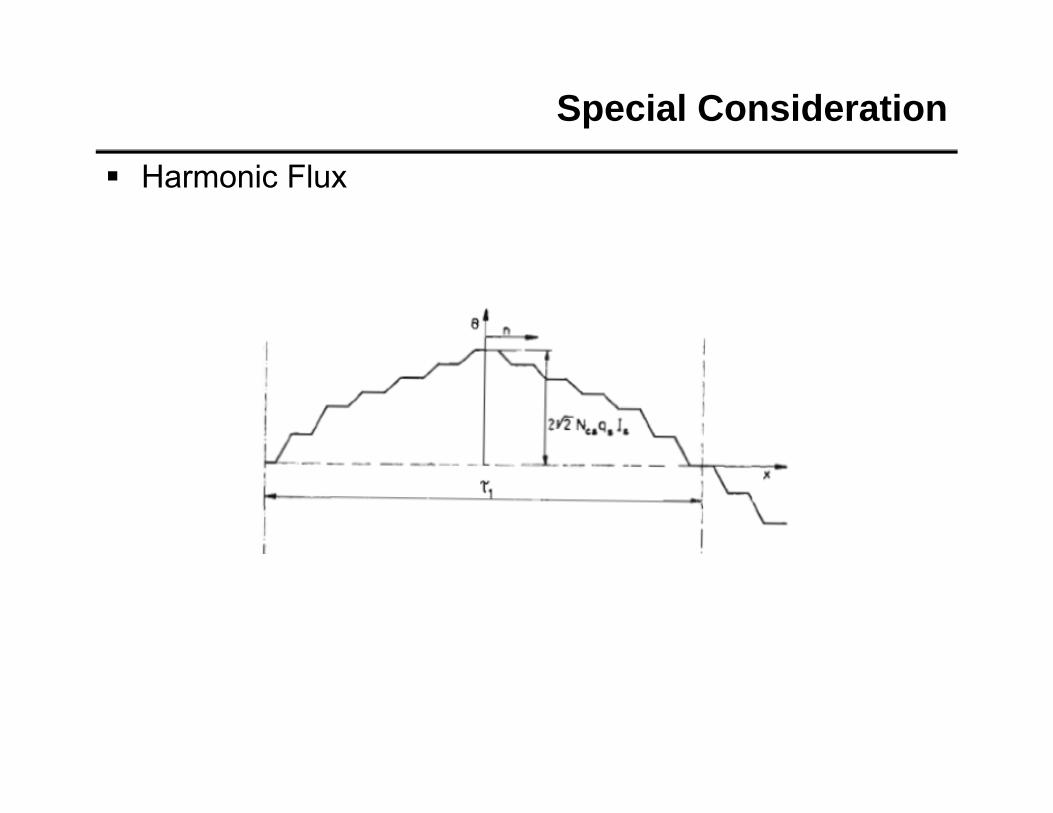
Special ConsiderationSpecial Consideration Harmonic Torques
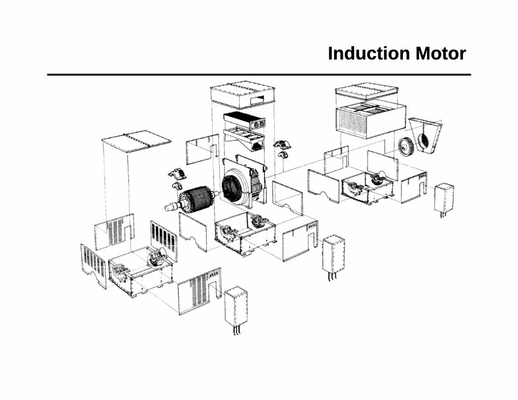
Basics, type characteristics, load characteristics, and modeling • Induction motor - General data, principle of
operation and nameplate information describing motormotor
• Motor types and characteristics, application consideration
• Load types and characteristics, application consideration
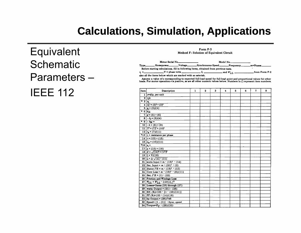
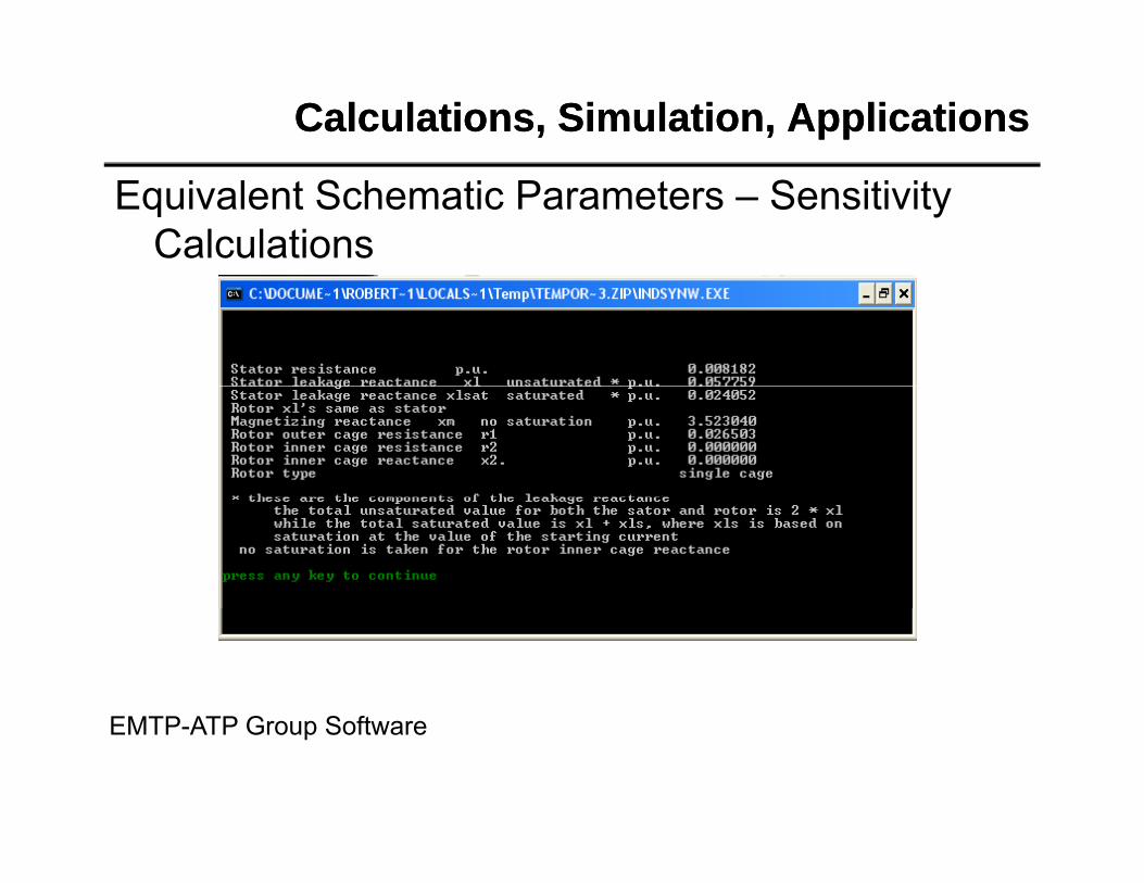
• Motor model• Motor model• Equivalent motor parameters• Other considerationOther consideration
Induction MotorInduction Motor
Induction MotorInduction Motor
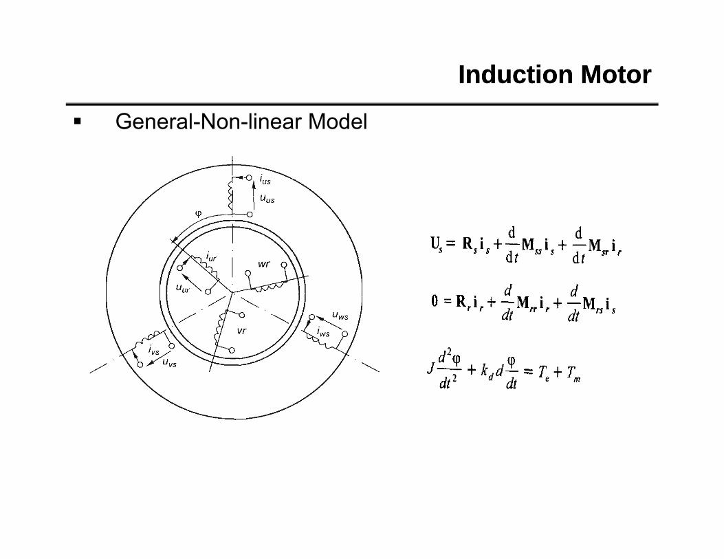
General-Non-linear Model
Induction MotorInduction Motor
Clark’s Transform
Induction MotorInduction Motor
Steady State Us=const
Induction MotorInduction Motor
Induction MotorInduction Motor
Induction MotorInduction Motor
Induction MotorInduction Motor
Induction Motor
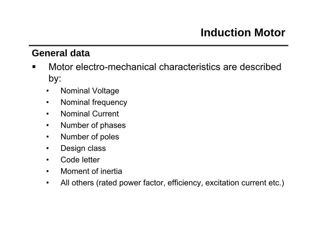
General data Motor electro-mechanical characteristics are described
bby:• Nominal Voltage• Nominal frequency• Nominal Current• Number of phases• Number of poles• Number of poles• Design class• Code letter
M f i i• Moment of inertia• All others (rated power factor, efficiency, excitation current etc.)
Induction Motor
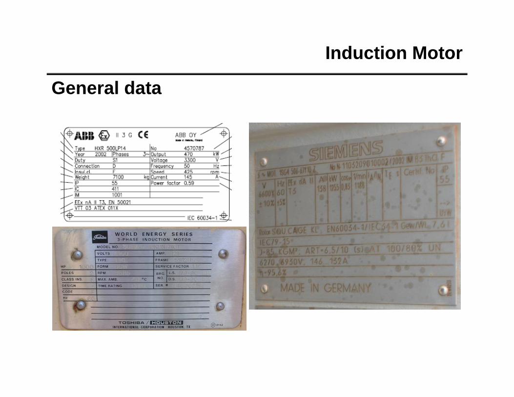
General data
Induction Motor
General data
Induction Motor
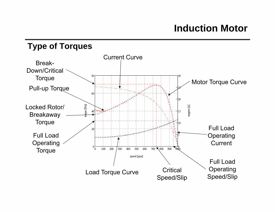
Type of TorquesCurrent Curve
Break-
Motor Torque CurvePull-up Torque
Down/Critical Torque
Locked Rotor/ Breakaway
Torque
Full Load Operating
Full Load Operating Current
Load Torque Curve
p gTorque
Full Load Operating Critical Load Torque CurveSpeed/SlipSpeed/Slip
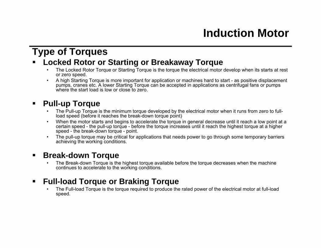
Induction MotorType of Torques Locked Rotor or Starting or Breakaway Torque
• The Locked Rotor Torque or Starting Torque is the torque the electrical motor develop when its starts at rest or zero speed.
• A high Starting Torque is more important for application or machines hard to start - as positive displacement pumps, cranes etc. A lower Starting Torque can be accepted in applications as centrifugal fans or pumps where the start load is low or close to zero.
Pull-up Torque• The Pull-up Torque is the minimum torque developed by the electrical motor when it runs from zero to full-
load speed (before it reaches the break-down torque point)• When the motor starts and begins to accelerate the torque in general decrease until it reach a low point at a
certain speed - the pull-up torque - before the torque increases until it reach the highest torque at a higher speed - the break-down torque - point.
• The pull-up torque may be critical for applications that needs power to go through some temporary barriers hi i h ki di iachieving the working conditions.
Break-down Torque• The Break-down Torque is the highest torque available before the torque decreases when the machine
continues to accelerate to the working conditions.
Full-load Torque or Braking Torque• The Full-load Torque is the torque required to produce the rated power of the electrical motor at full-load
speed.
Induction Motor
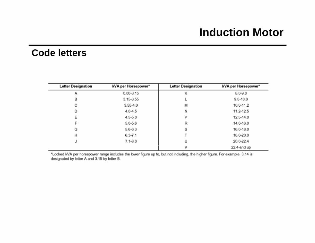
Code letters
Induction Motor
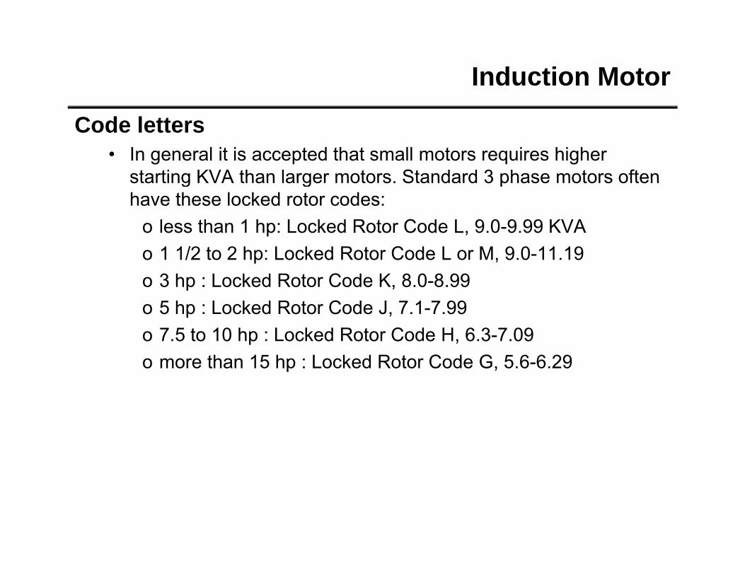
Code letters• In general it is accepted that small motors requires higher
starting KVA than larger motors Standard 3 phase motors oftenstarting KVA than larger motors. Standard 3 phase motors often have these locked rotor codes:
o less than 1 hp: Locked Rotor Code L, 9.0-9.99 KVAo 1 1/2 to 2 hp: Locked Rotor Code L or M 9 0 11 19o 1 1/2 to 2 hp: Locked Rotor Code L or M, 9.0-11.19o 3 hp : Locked Rotor Code K, 8.0-8.99o 5 hp : Locked Rotor Code J, 7.1-7.99o 7.5 to 10 hp : Locked Rotor Code H, 6.3-7.09o more than 15 hp : Locked Rotor Code G, 5.6-6.29
Induction Motor Design Type
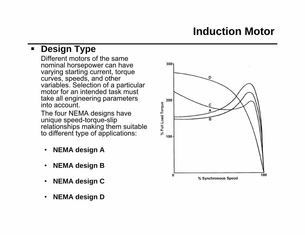
Different motors of the same nominal horsepower can have varying starting current torquevarying starting current, torque curves, speeds, and other variables. Selection of a particular motor for an intended task must take all engineering parameters i t tinto account.The four NEMA designs have unique speed-torque-slip relationships making them suitable to different type of applications:to different type of applications:
• NEMA design A
• NEMA design B
• NEMA design C
• NEMA design D
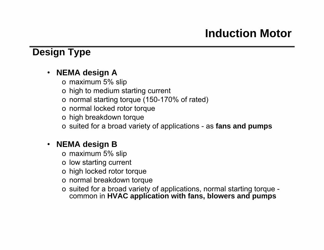
Induction MotorDesign Type
• NEMA design Ao maximum 5% slipo high to medium starting current o normal starting torque (150-170% of rated)o normal locked rotor torqueo normal locked rotor torqueo high breakdown torqueo suited for a broad variety of applications - as fans and pumps
• NEMA design Bo maximum 5% slipo low starting currento high locked rotor torqueo high locked rotor torqueo normal breakdown torqueo suited for a broad variety of applications, normal starting torque -
common in HVAC application with fans, blowers and pumps
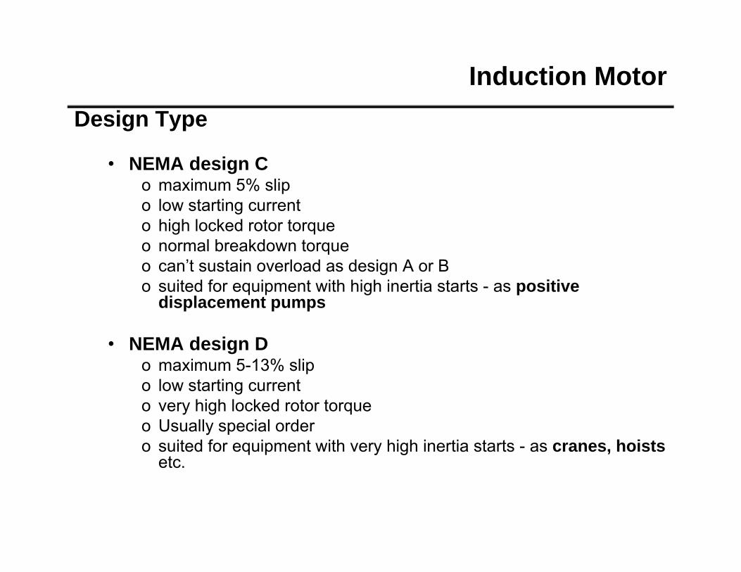
Induction MotorDesign Type
• NEMA design Co maximum 5% slipo low starting currento high locked rotor torqueo normal breakdown torqueo normal breakdown torqueo can’t sustain overload as design A or Bo suited for equipment with high inertia starts - as positive
displacement pumps
• NEMA design Do maximum 5-13% slipo low starting currentgo very high locked rotor torqueo Usually special ordero suited for equipment with very high inertia starts - as cranes, hoists
etc.etc.
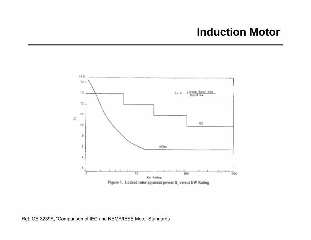
Induction Motor
Induction Motor
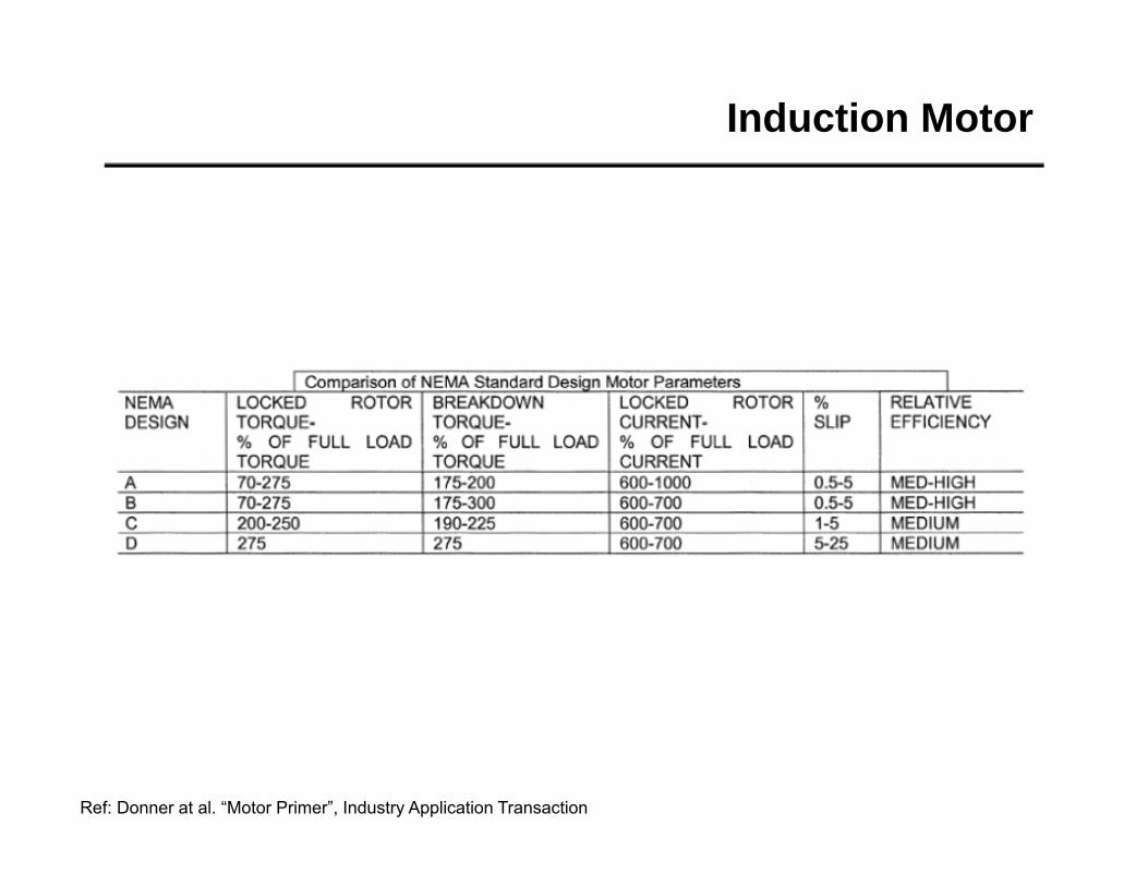
Ref: Donner at al. “Motor Primer”, Industry Application Transaction
Induction Motor
Ref: GE-3239A, “Comparison of IEC and NEMA/IEEE Motor Standards
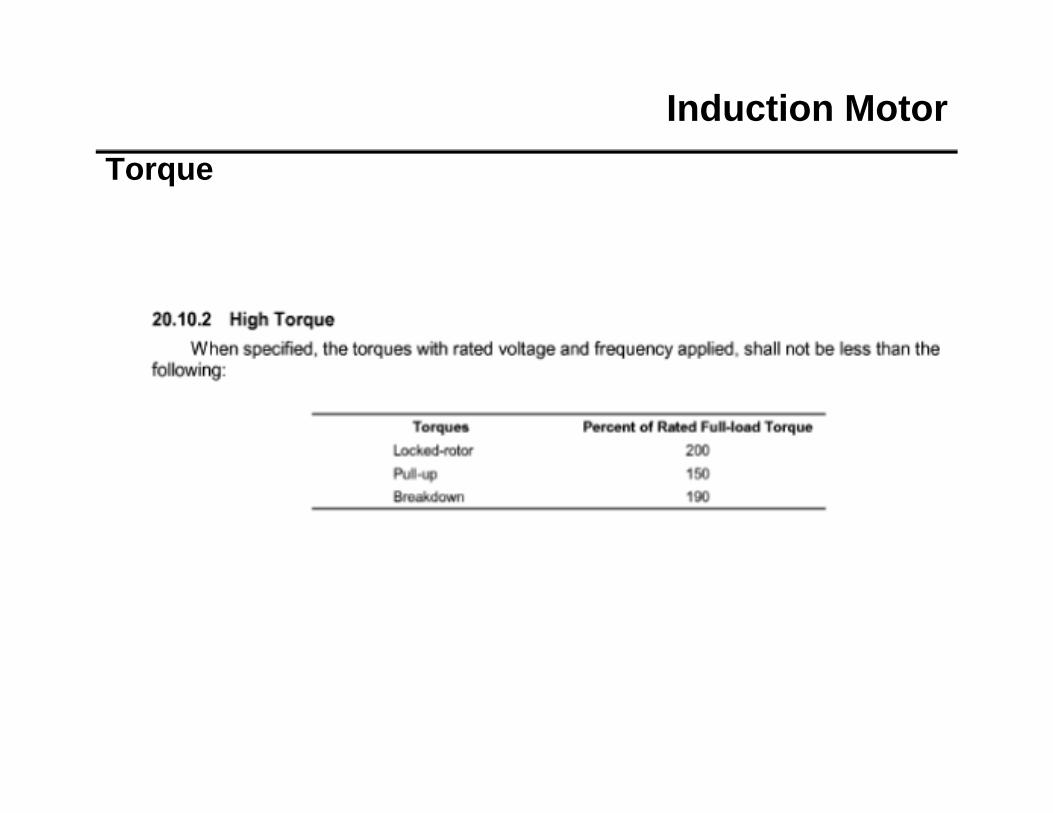
Induction MotorTorque
Induction MotorTorque
Induction MotorInertia
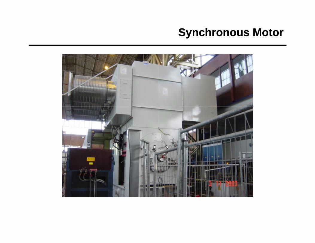
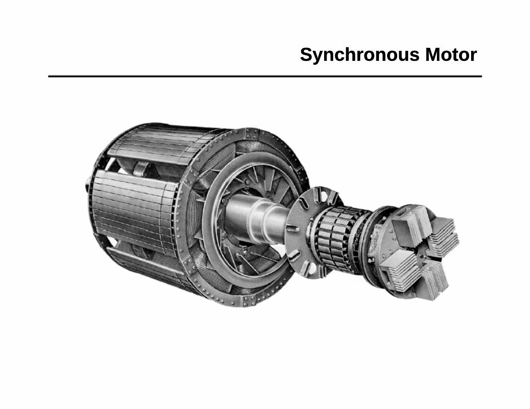
SynchronousSynchronous Motor
Synchronous MotorSynchronous Motor
Synchronous MotorSynchronous Motor
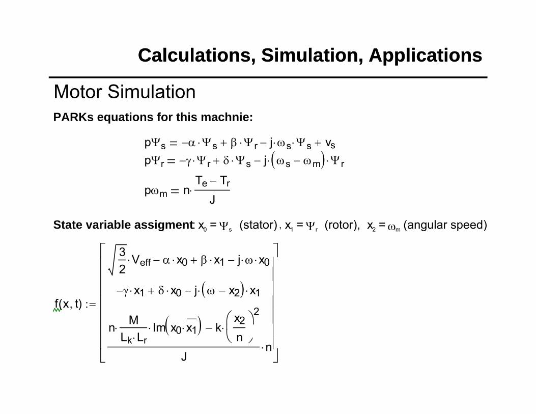
General-Non-linear Model
Synchronous MotorSynchronous Motor
Park’s Transform
Synchronous MotorSynchronous Motor
Steady State Us=const
Synchronous MotorSynchronous Motor
Synchronous MotorSynchronous Motor
Synchronous MotorSynchronous Motor
Synchronous MotorSynchronous Motor
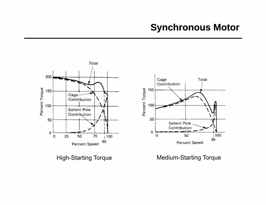
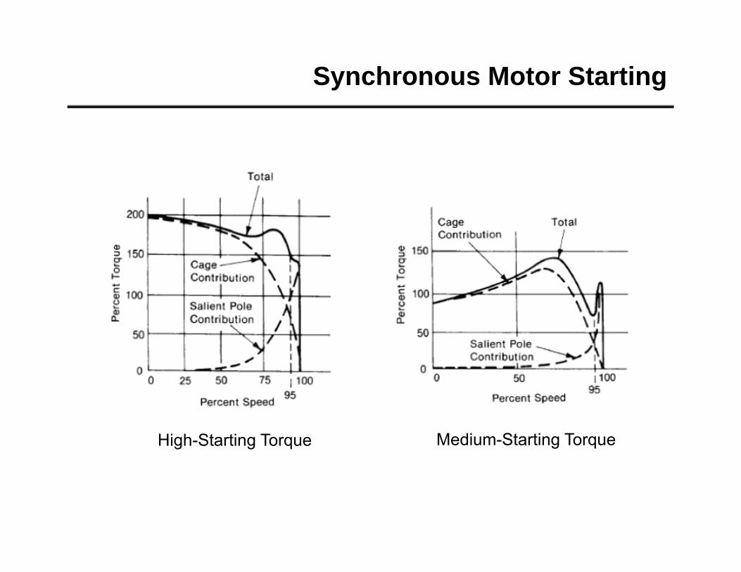
Synchronous MotorSynchronous Motor
High-Starting Torque Medium-Starting Torque
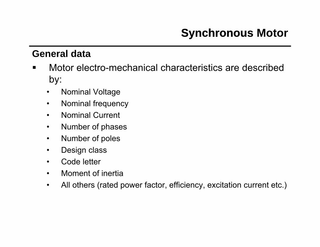
Synchronous Synchronous Motor
General data Motor electro-mechanical characteristics are described
bby:• Nominal Voltage• Nominal frequency• Nominal Current• Number of phases• Number of poles• Number of poles• Design class• Code letter
M f i i• Moment of inertia• All others (rated power factor, efficiency, excitation current etc.)
Synchronous Synchronous Motor
General data
Mechanical Train SystemMechanical Train System
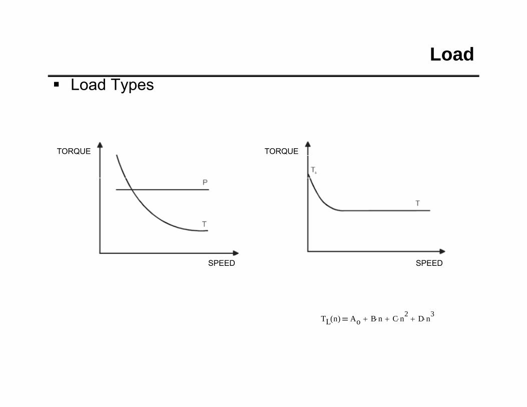
Load Load Types
TORQUE TORQUE
SPEED SPEED
TL s( ) TLRT Ta ns 1 s( ) k
TL n( ) TLRT Ta n( )k
k 1 2 3
Load Load Types
TORQUE TORQUE
SPEED SPEED
TL n( ) Ao B n C n2 D n3
Load Load Types
TORQUE
SPEED SPEED
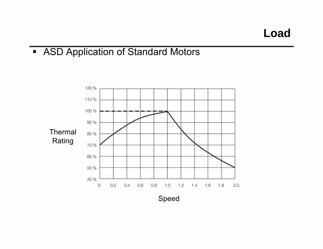
Load ASD Application of Standard Motors
Thermal RatingRating
Speed
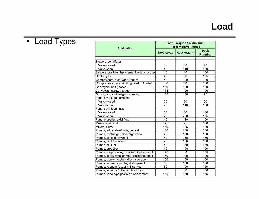
Load Load Types
Breakaway Accelerating Peak Running
Blowers centrifugal:
Load Torque as a Minimum Percent Drive TorqueApplication
Blowers, centrifugal:Valve closed 30 50 40Valve open 40 110 100
Fans, propeller, axial-flow 40 110 100Mixers, chemical 175 75 100Mixers, slurry 150 125 100Pumps, adjustable-blade, vertical 150 200 200Pumps, centrifugal, discharge open 40 150 150Pumps oil field flywheel 40 150 150Pumps, oil-field, flywheel 40 150 150Pumps, oil, lubricating 40 150 150Pumps, oil, fuel 40 150 150Pumps, propeller 40 100 100Pumps, reciprocating, positive displacement 175 30 175Pumps, screw-type, primed, discharge open 150 100 100Pumps, slurry-handling, discharge open 150 100 100P t bi t if l d ll 50 100 100Pumps, turbine, centrifugal, deep-well 50 100 100Pumps, vacuum (paper mill service) 60 100 150Pumps, vacuum (other applications) 40 60 100Pumps, vane-type positive displacement 150 150 175
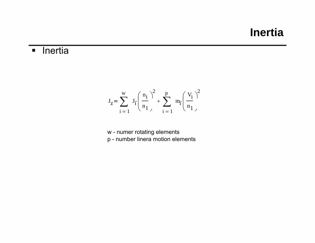
Inertia Inertia
Jz
wJi
nin1
2
p
miVin1
2
1i
n1 1i
n1
w - numer rotating elementsb li i lp - number linera motion elements
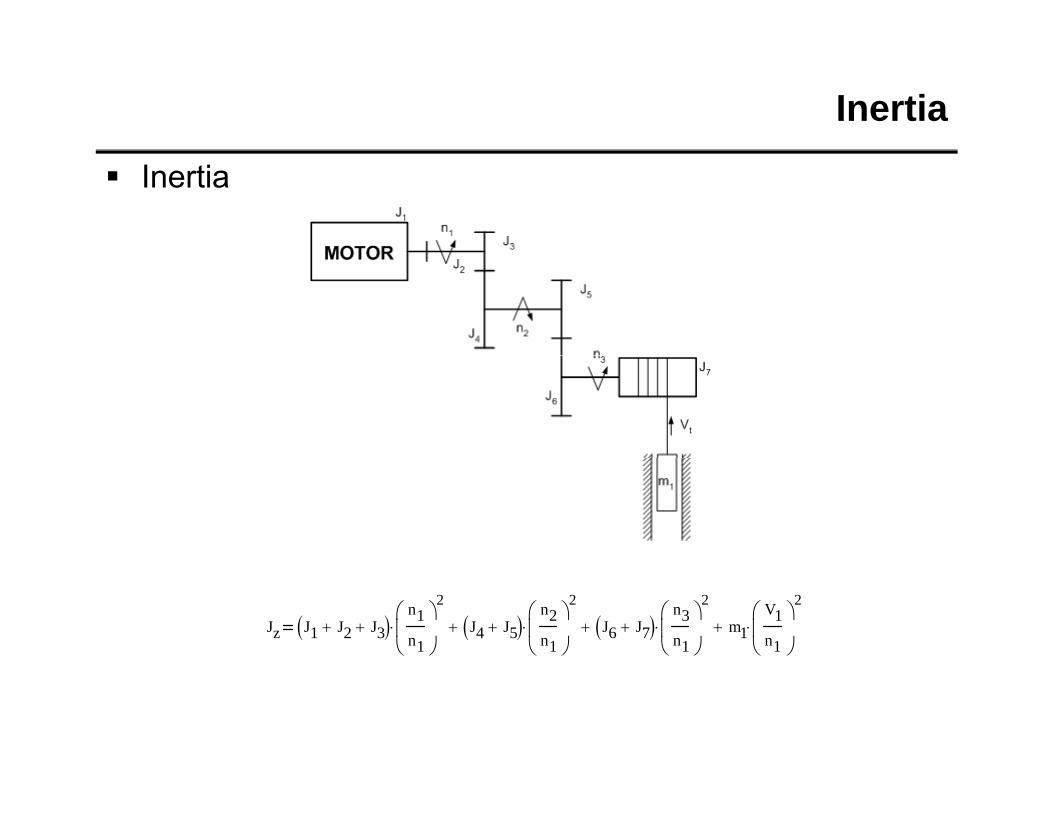
Inertia
Inertia
Jz J1 J2 J3 n1n1
2
J4 J5 n2n1
2
J6 J7 n3n1
2
m1V1n1
2
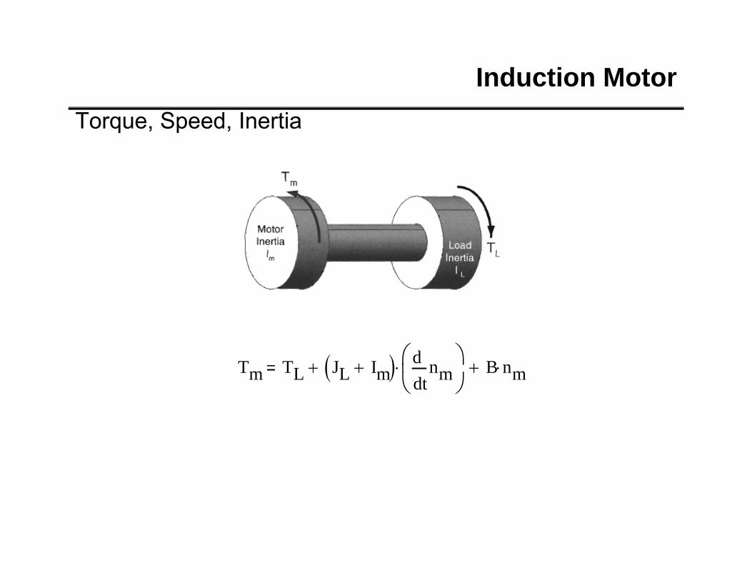
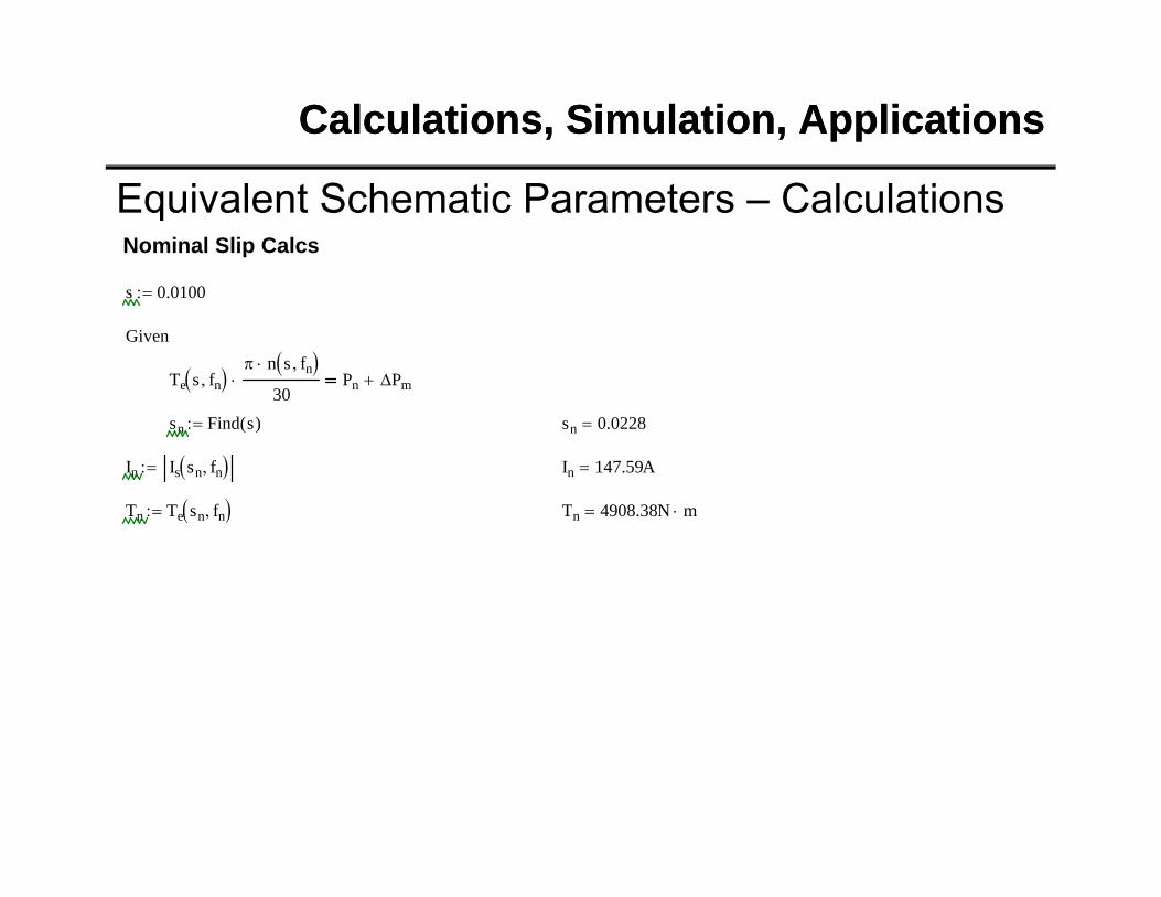
Induction MotorTorque, Speed, Inertia
Tm TL JL Im tnm
dd
B nm
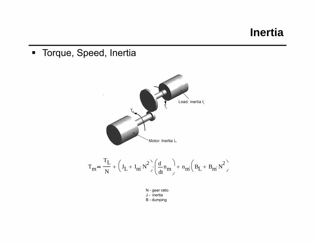
Inertia
Torque, Speed, Inertia
TTL
JL I N2
nd
n BL B N2
N - gear ratioJ - inertia
Tm NJL Im N t
nmd
nm BL Bm N
B - dumping
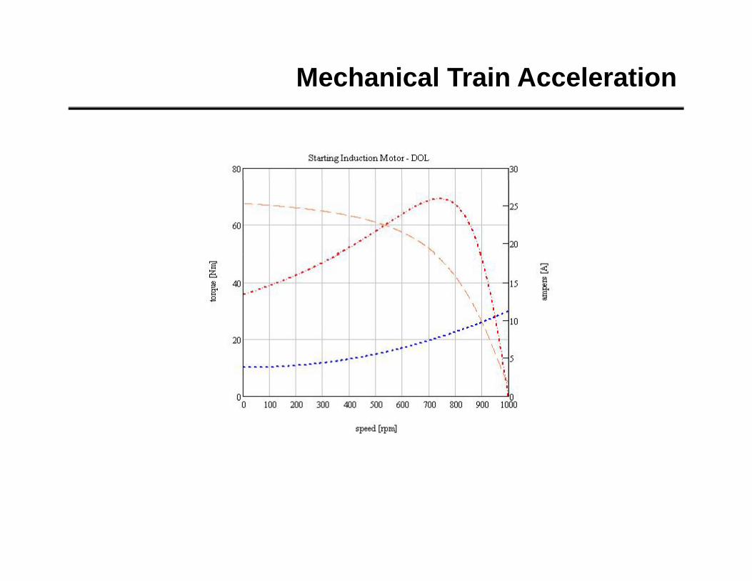
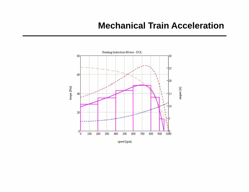
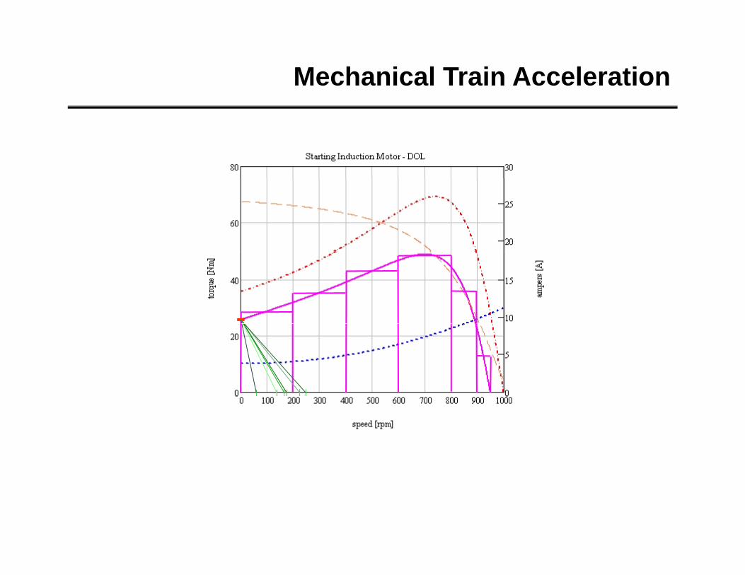
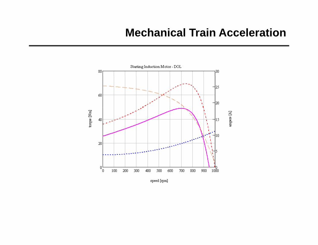
Mechanical Train Acceleration
Mechanical Train Acceleration
Graphical Method
Mechanical Train Acceleration
Mechanical Train Acceleration
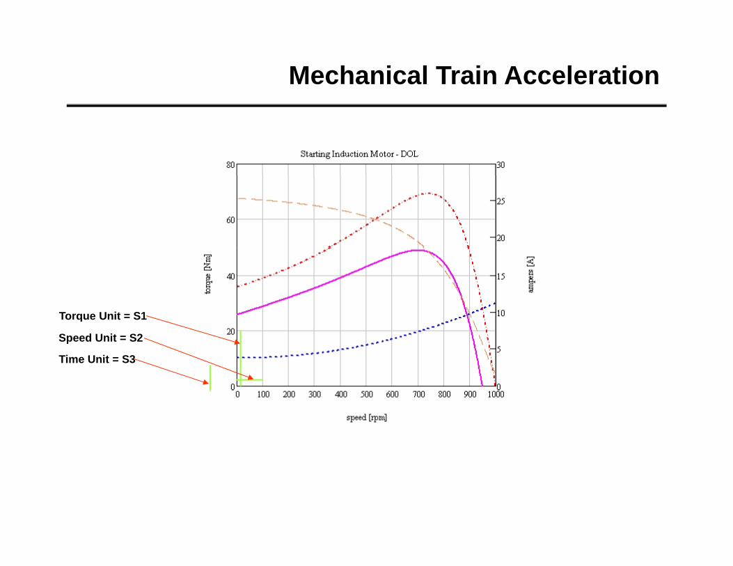
Mechanical Train Acceleration
Mechanical Train Acceleration
Torque Unit = S1Torque Unit S1
Speed Unit = S2
Time Unit = S3
Mechanical Train Acceleration
S1 - scale of speed acceleration
S2 - scale of torque acceleration
S3 - scale of time required to accelerate train with acceleration torque from one speed toS3 - scale of time required to accelerate train with acceleration torque from one speed to another
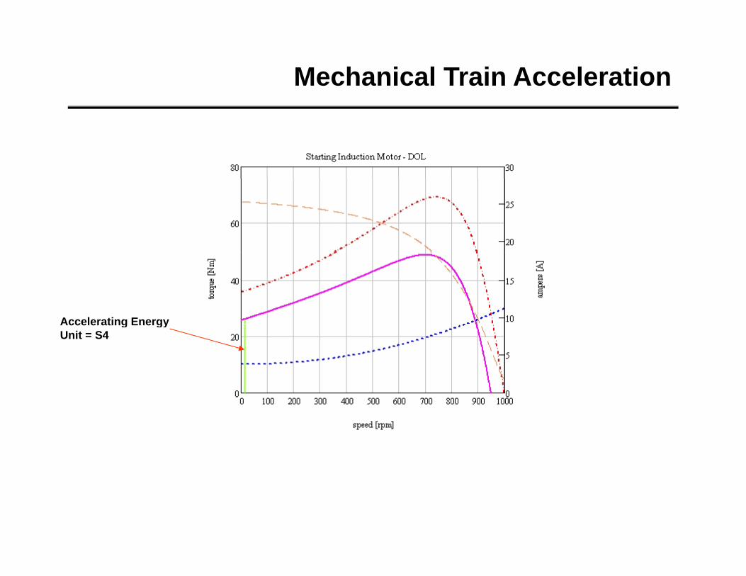
S4 - scale of dynamic energy needed for acceleration
S2 S4S1 S3
S1 100RPMdiv1
S 20N·m
S2 20div2
S30.1secdiv3
S4S2 S3
k S4 0.04S4 S1k S4 0.04
Jtrain 0.431 kg m2
OA Jtrain
30 S4 OA 1.128m2 kg
Mechanical Train Acceleration
Accelerating EnergyAccelerating Energy Unit = S4
Mechanical Train Acceleration
Mechanical Train Acceleration
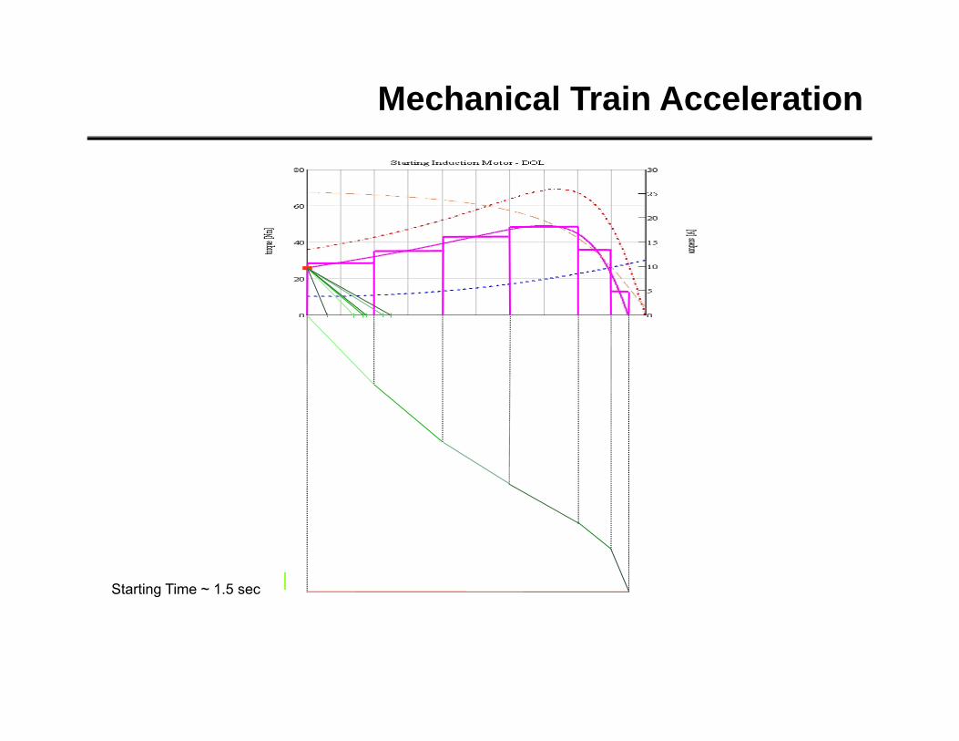
Mechanical Train Acceleration
Starting Time ~ 1.5 sec
Mechanical Train Acceleration
Calculations Method
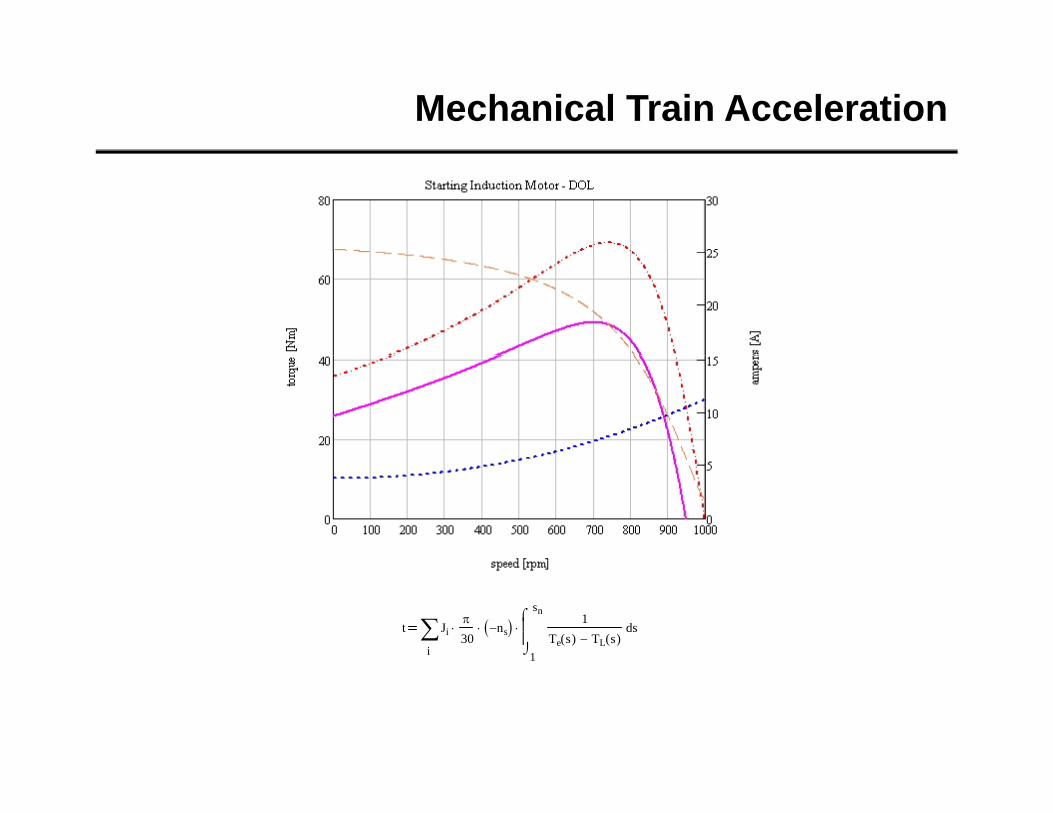
Mechanical Train Acceleration
Mechanical Train Acceleration
t
i
Ji
30 ns
1
sn
s1
Te s( ) TL s( )
d
Mechanical Train Acceleration
t1 Js Jm
30 ns
sn
s1
Me s fn U2 Mo s( )
d t1 1.37
1
Mechanical Train Acceleration
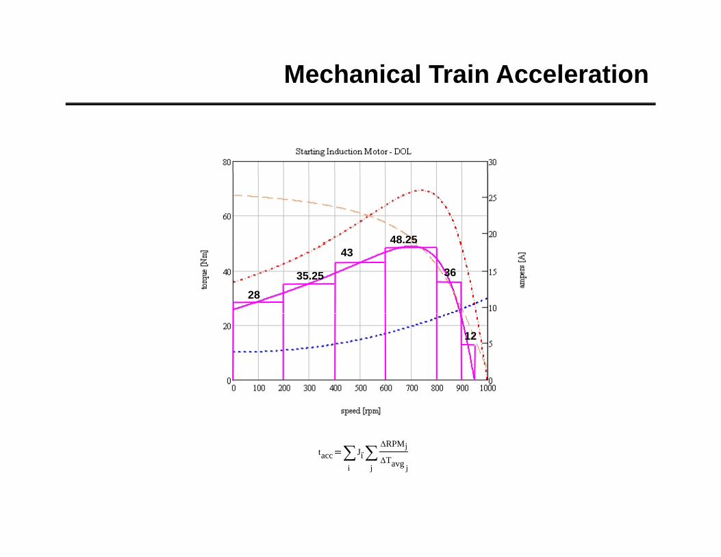
In Between Method
Mechanical Train Acceleration
Mechanical Train Acceleration
48.25
28
35.25
43
36
12
tacc JiRPMjtacc
i
Jij
Tavg j
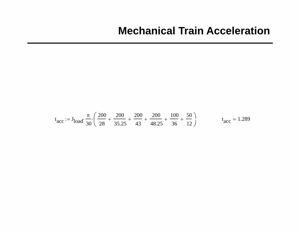
Mechanical Train Acceleration
tacc Jload
30
20028
20035.25
20043
200
48.25
10036
5012
tacc 1.289
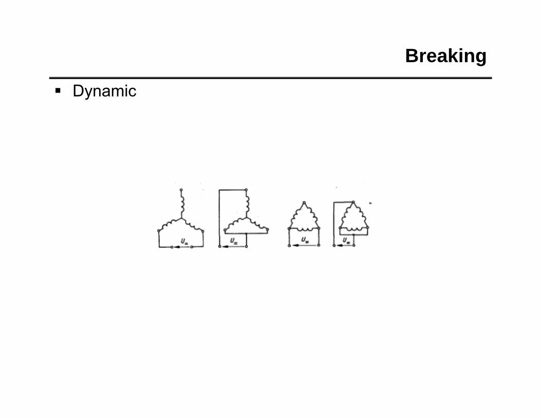
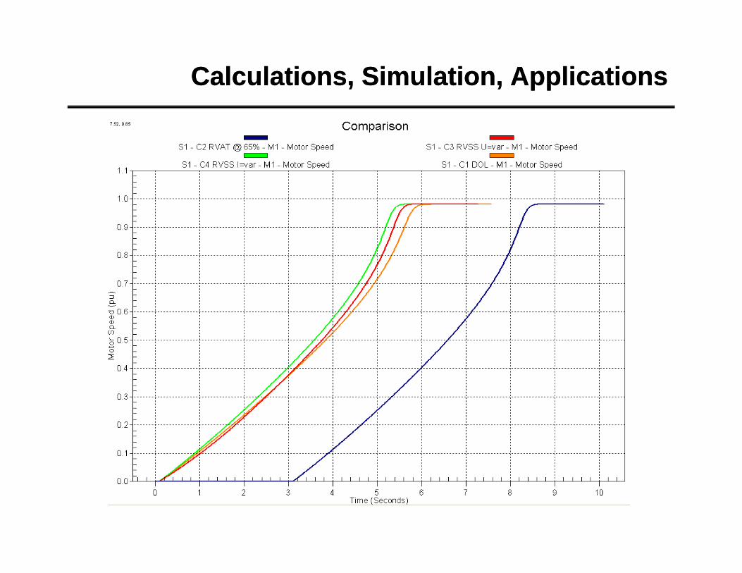
Starting, Operation and Breaking MethodsStarting, Operation and Breaking Methods
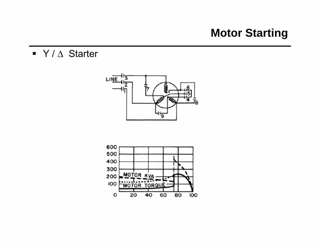
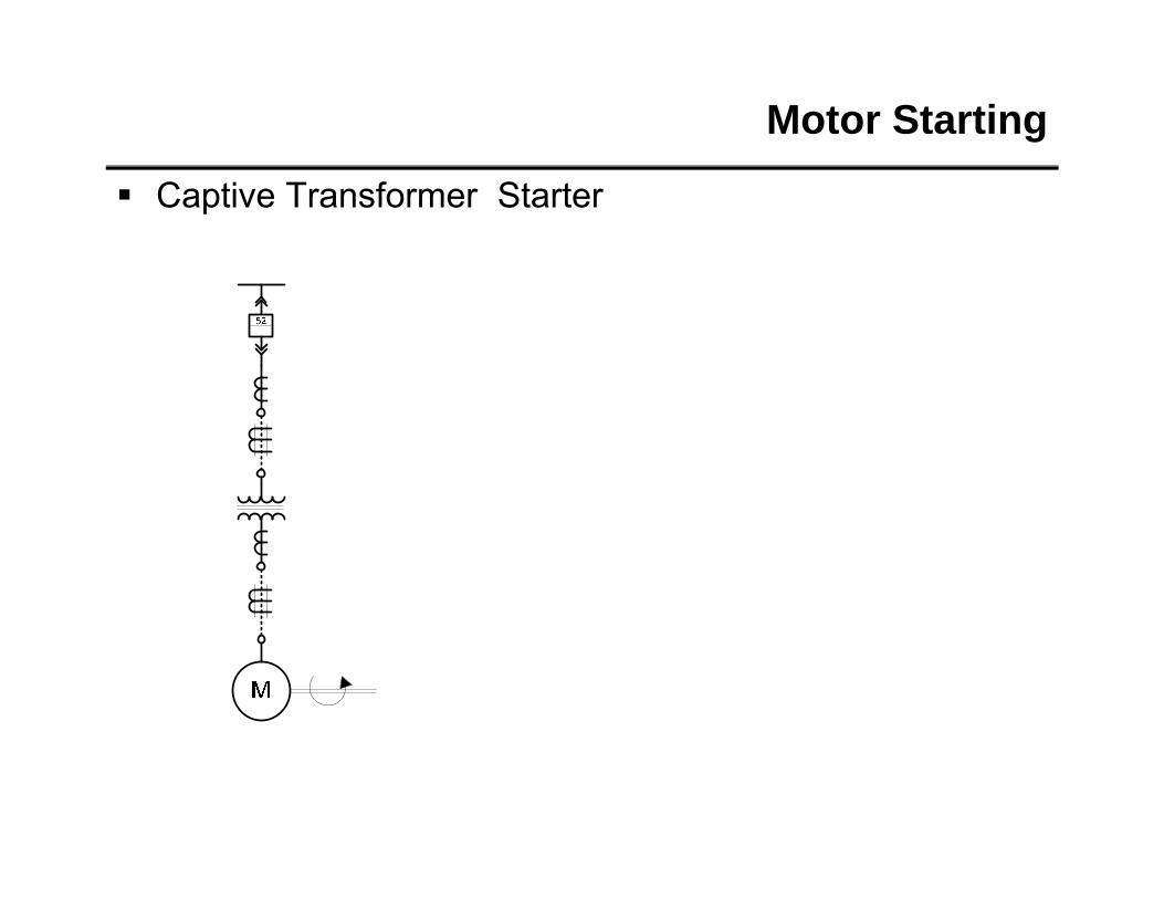
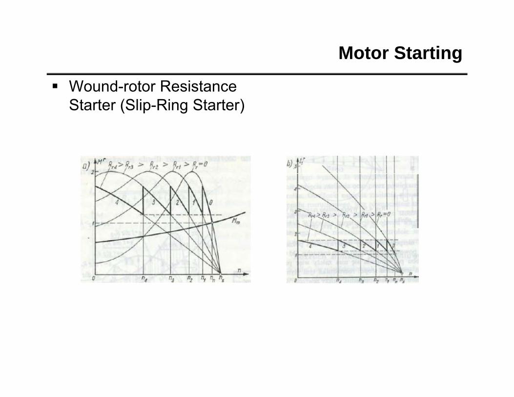
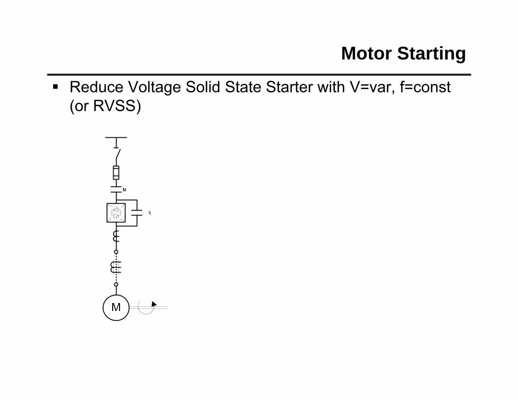
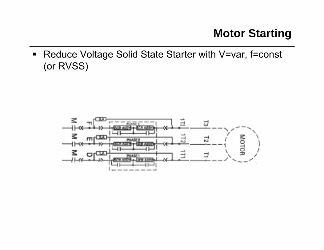
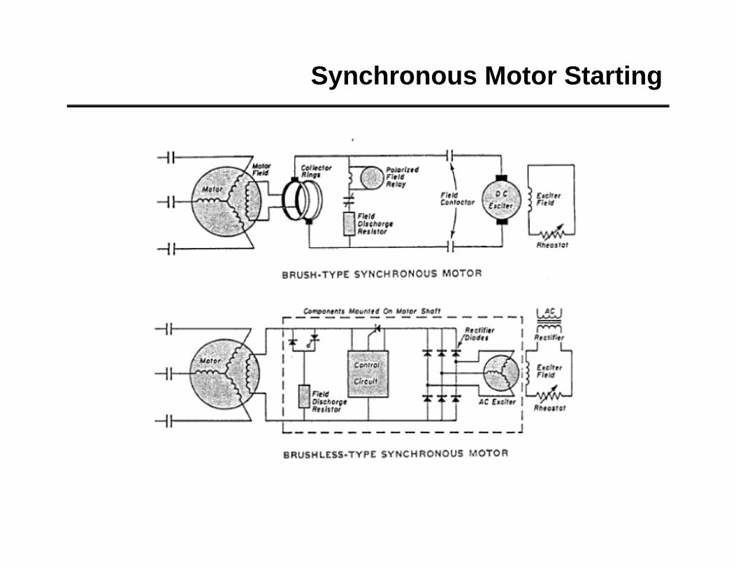
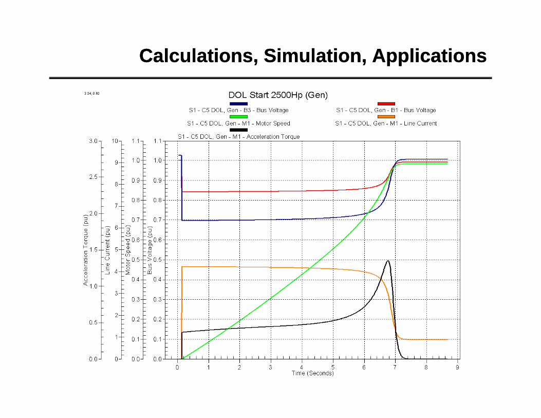
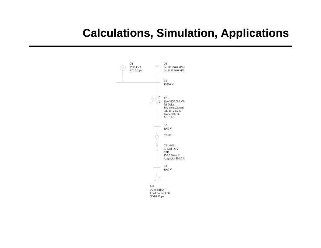
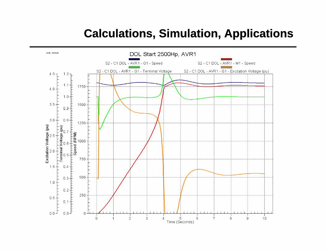
Motor Starting
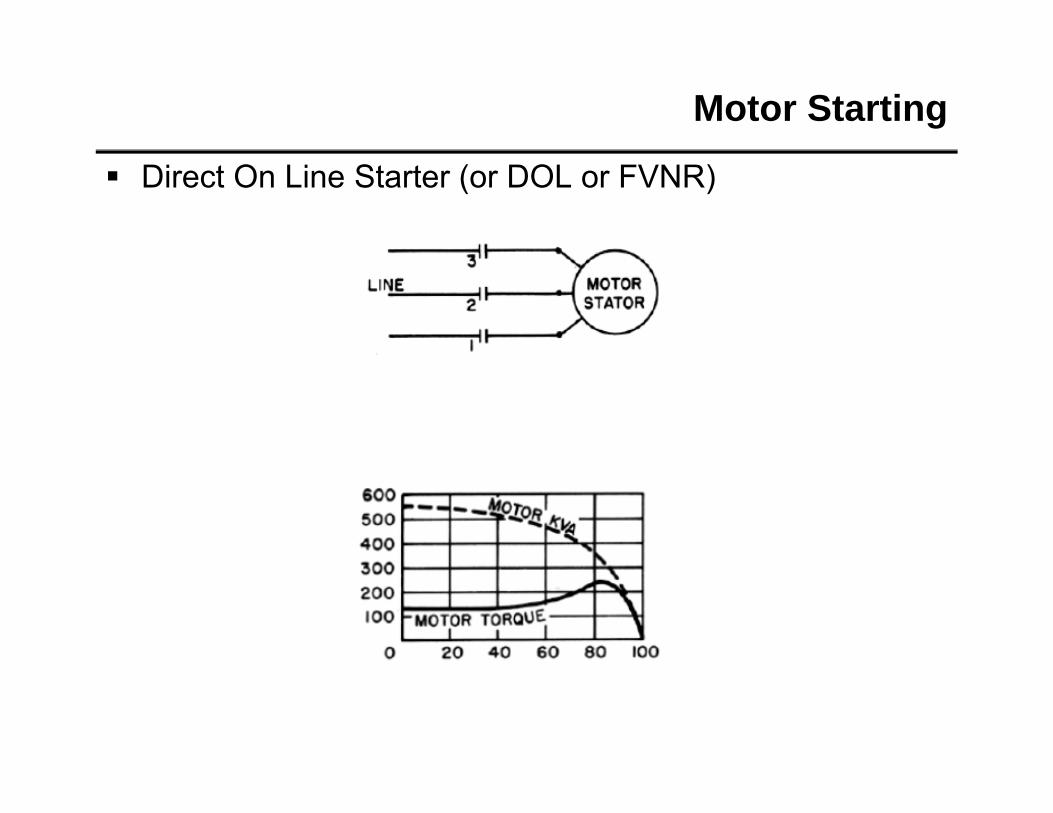
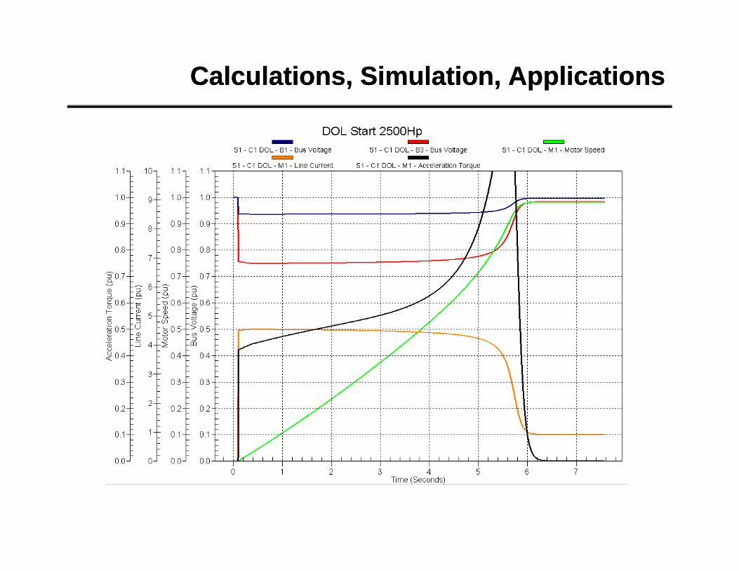
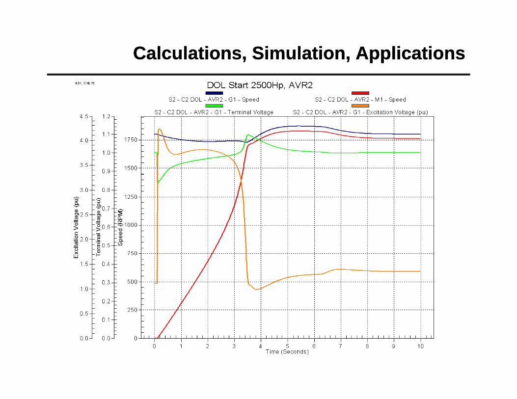
Direct On Line Starter (or DOL or FVNR)
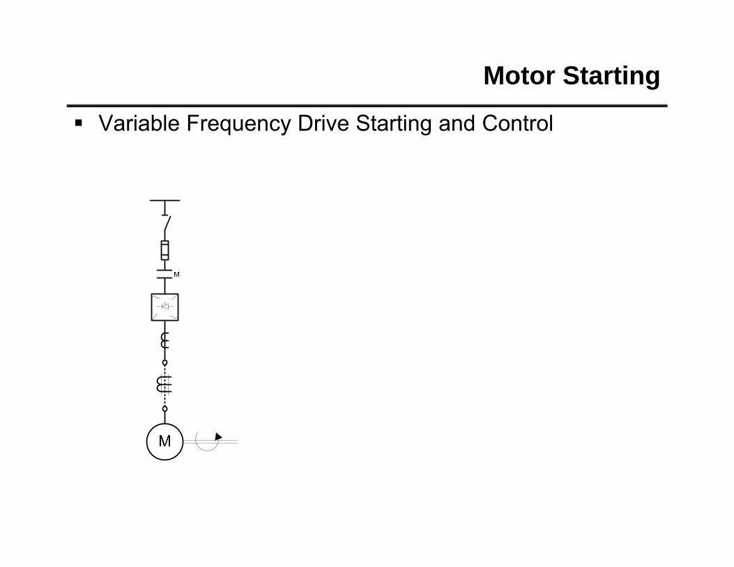
Motor Starting
Direct On Line Starter (or DOL or FVNR)
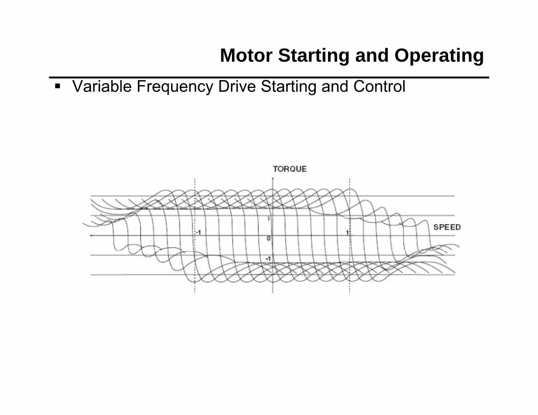
Motor Starting
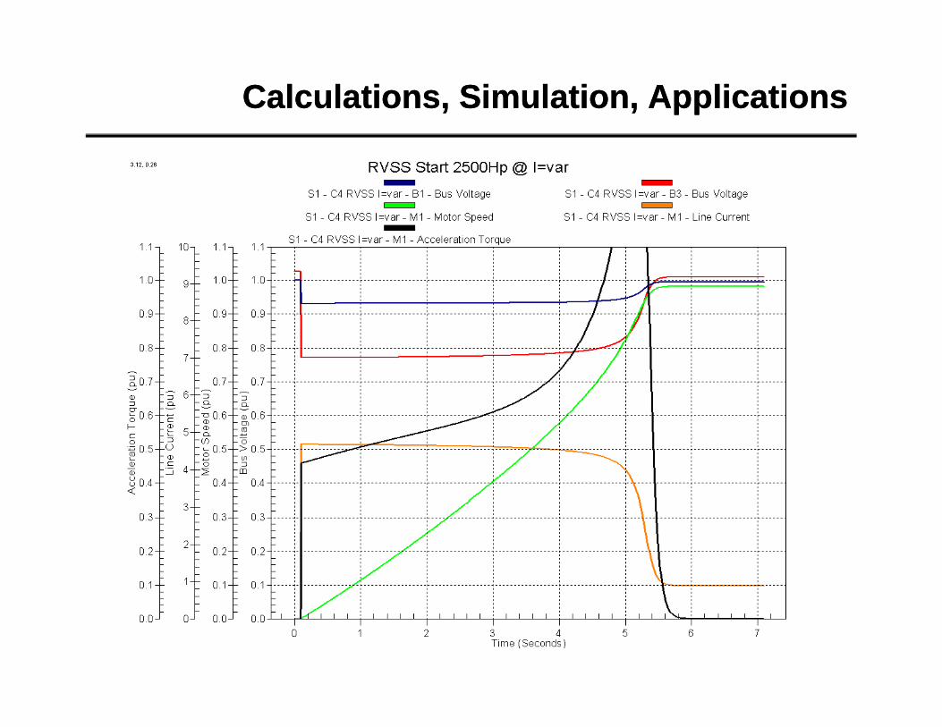
Reduce Voltage Resistor/Reactor Starter
Motor Starting
Reduce Voltage Resistor/Reactor Starter
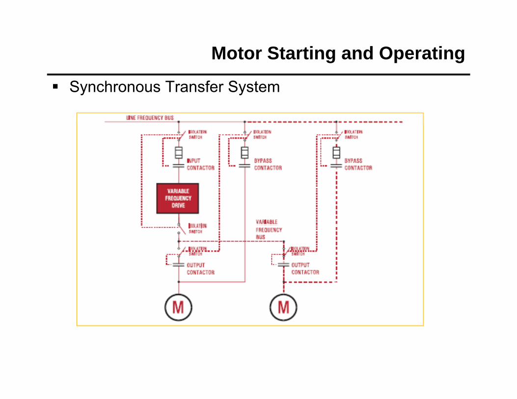
Motor Starting
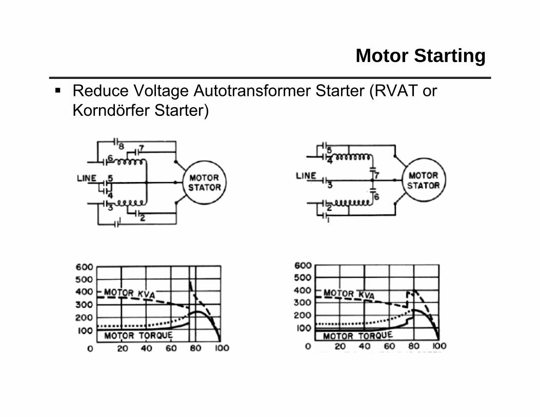
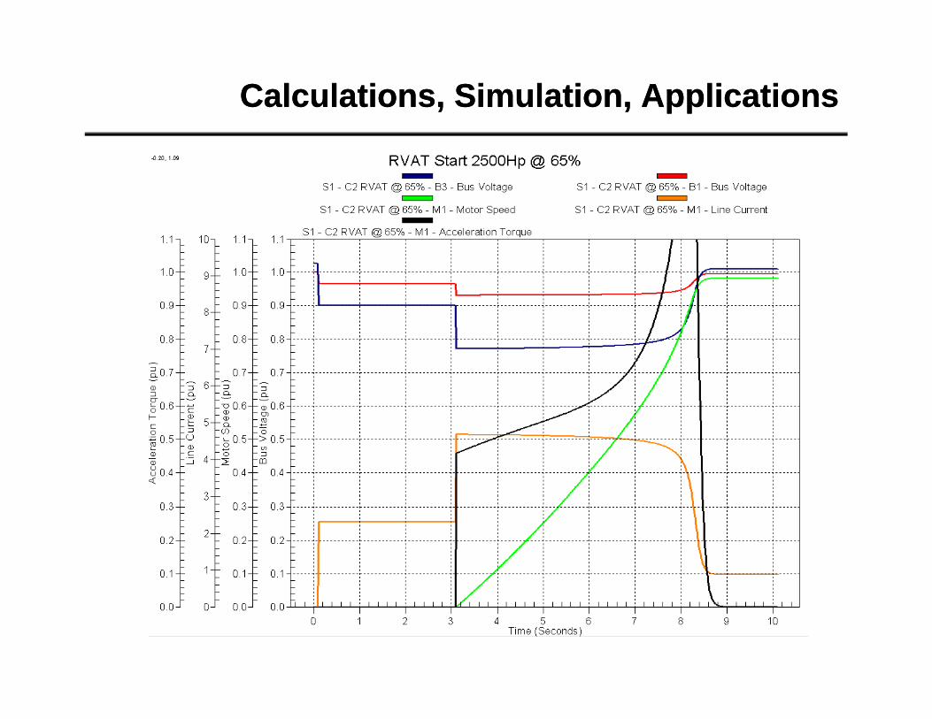
Reduce Voltage Autotransformer Starter (RVAT or Korndörfer Starter)
Motor Starting
Reduce Voltage Autotransformer Starter (RVAT or Korndörfer Starter)
Motor Starting
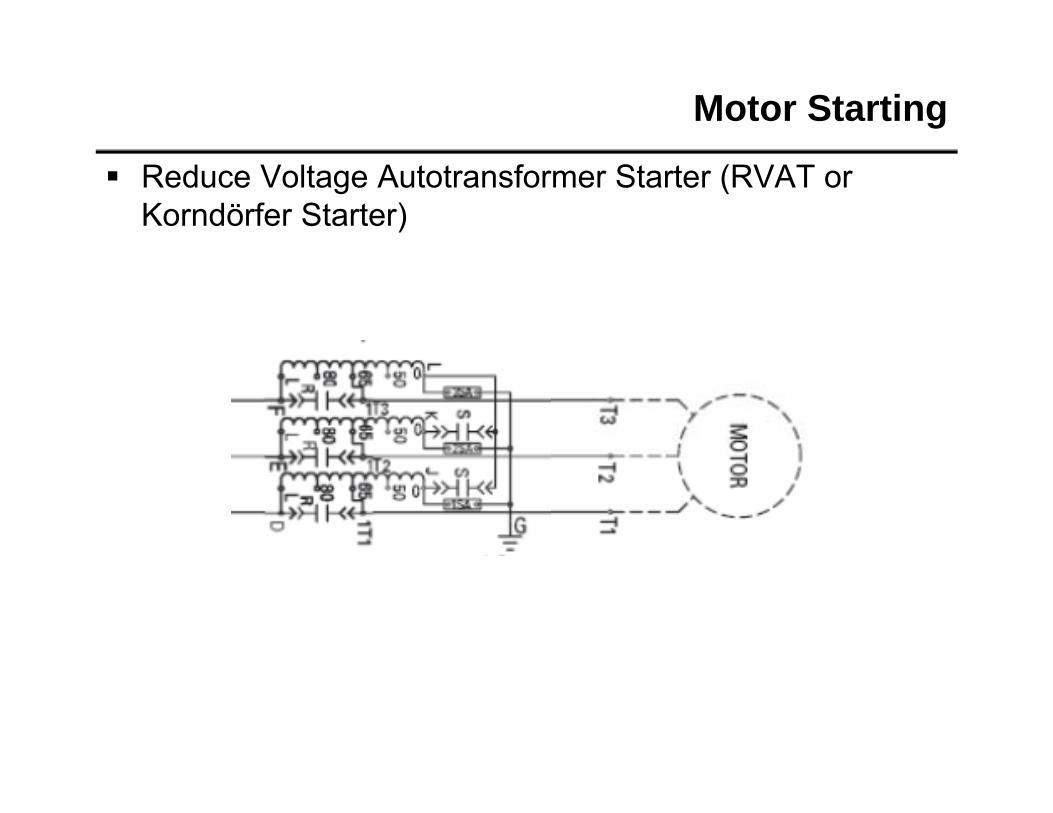
Reduce Voltage Autotransformer Starter (RVAT or Korndörfer Starter)
60 Avg Line Volt (V) kW Power (kW) kvar Power (kvar) T. C. Used (%) Hottest Stator RTD (° C)
0
1000
2000
0 200 400 600 800 1000 12000
10
20 Motor Load (x FLA)
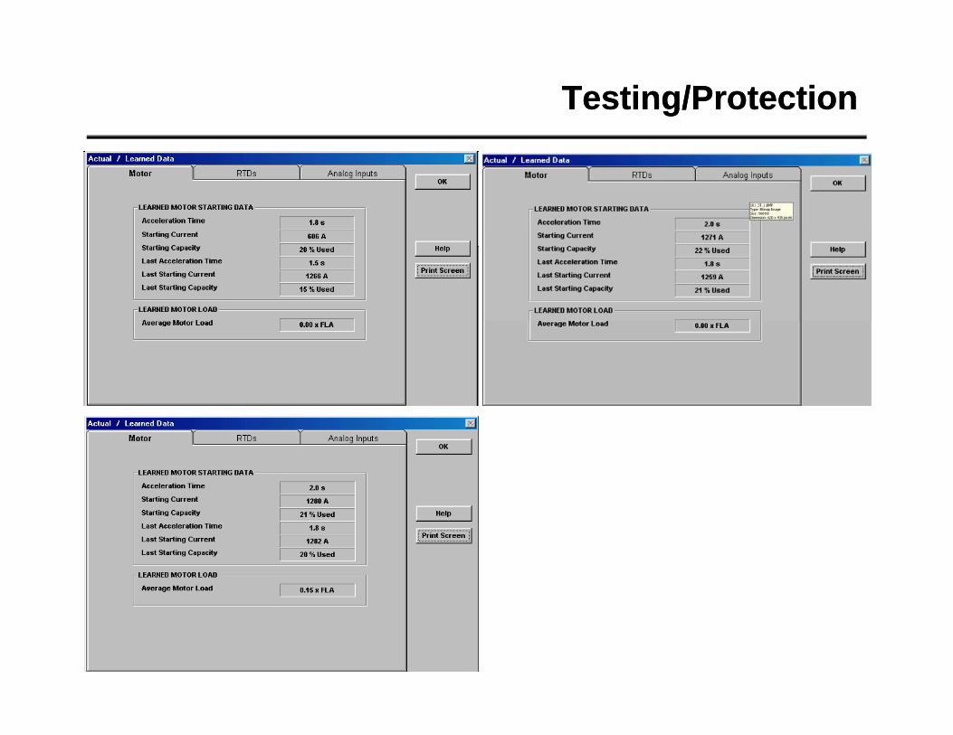
Testing/ProtectionTesting/Protection
6000
7000
8000
80
100
120
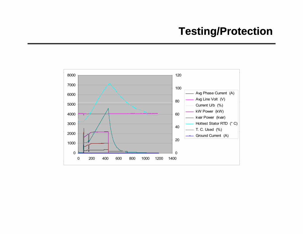
Avg Phase Current (A) Avg Line Volt (V)
3000
4000
5000
40
60
80 Current U/b (%) kW Power (kW) kvar Power (kvar) Hottest Stator RTD (° C) T. C. Used (%)
0
1000
2000
0 200 400 600 800 1000 1200 14000
20 Ground Current (A)
Testing/ProtectionTesting/Protection
120
9
10
80
100
7
8
60
4
5
6
Hottest Stator RTD (° C)
T. C. Used (%)
Motor Load (x FLA)
20
40
2
3
00 1000 2000 3000 4000 5000 6000 7000
0
1
Testing/ProtectionTesting/ProtectionLAST "BLOW" - Phase A Current (Amps)
2000
3000
4000
LAST "BLOW" Phase B Current (Amps)
2000
3000
4000
-2000
-1000
0
1000
Tim
e
-47.
91
22.9
1
93.7
3
164.
56
235.
38
306.
2
377.
02
447.
84
518.
66
589.
49
660.
31
731.
13
801.
95
872.
77
943.
59
1014
.41
1085
.24
1156
.06
1226
.88
1297
.7
1368
.52
1439
.34
1510
.17
1580
.99
1651
.81
1722
.63
1793
.45
1864
.27
1935
.09
2005
.92
CU
RR
ENT
( A
Phase A Current (Amps)
-2000
-1000
0
1000
Tim
e
-47.
91
22.9
1
93.7
3
164.
56
235.
38
306.
2
377.
02
447.
84
518.
66
589.
49
660.
31
731.
13
801.
95
872.
77
943.
59
1014
.41
1085
.24
1156
.06
1226
.88
1297
.7
1368
.52
1439
.34
1510
.17
1580
.99
1651
.81
1722
.63
1793
.45
1864
.27
1935
.09
2005
.92
CU
RR
ENT
( A
Phase B Current (Amps)
-4000
-3000
TIME (ms)
-4000
-3000
TIME (ms)
LAST "BLOW" Phase C Current (Amps) LAST "BLOW" AN(AB) Voltage (V)
1000
2000
3000
4000
ENT
(A
2000
4000
6000
8000
GE
(V)
-4000
-3000
-2000
-1000
0
Tim
e
-47.
91
22.9
1
93.7
3
164.
56
235.
38
306.
2
377.
02
447.
84
518.
66
589.
49
660.
31
731.
13
801.
95
872.
77
943.
59
1014
.41
1085
.24
1156
.06
1226
.88
1297
.7
1368
.52
1439
.34
1510
.17
1580
.99
1651
.81
1722
.63
1793
.45
1864
.27
1935
.09
2005
.92
CU
RR
E Phase C Current (Amps)
-8000
-6000
-4000
-2000
0Ti
me
-49.
99
18.7
5
87.4
9
156.
22
224.
96
293.
7
362.
44
431.
18
499.
92
568.
66
637.
39
706.
13
774.
87
843.
61
912.
35
981.
09
1049
.83
1118
.56
1187
.3
1256
.04
1324
.78
1393
.52
1462
.26
1530
.99
1599
.73
1668
.47
1737
.21
1805
.95
1874
.69
1943
.43
2012
.16
VOLT
AG AN(AB) Voltage (V)
TIME (ms) TIME (ms)
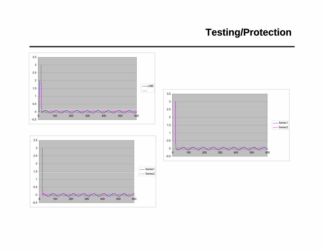
Testing/ProtectionTesting/Protection
2.5
3
3.5
0.5
1
1.5
2
LINE
2 5
3
3.5
-0.5
00 100 200 300 400 500 600
0 5
1
1.5
2
2.5
Series1Series2
3.5
-0.5
0
0.5
0 100 200 300 400 500 600
1.5
2
2.5
3
3.5
Series1
-0.5
0
0.5
1
1.5
0 100 200 300 400 500 600
Series2
Questions?Questions?
ReferencesReferences
ReferencesReferences
ReferencesReferences
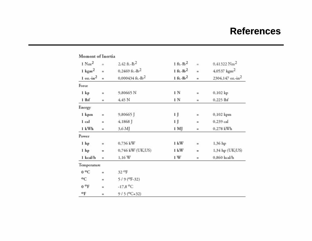
ReferencesReferences
• Fitzgerald & Kingsley, Electric Machinery, McGraw-Hill, 1961• Liwschitz-Garik, Whipple, A-C Machines, Van Nostrand, 1961• Say, M.G., Alternating Current Machines, John Wiley & Sons, 1976
Gra Electrical Machines and Dri e S stems John Wile & Sons 1989• Gray, Electrical Machines and Drive Systems, John Wiley & Sons, 1989• Leonhard, Control of Electrical Drives, Spinger-Verlag, 1985• Maxwell, James Clerk, A Treatise on Electricity and Magnetism, third edition, 1891• IEEE Standard 519-1992 “IEEE Recommended Practices and Requirements
for Harmonic Control in Electrical Power Systems”, IEEE Press SH15453, New York, 1993• Hammond, P. Power Factor Correction of Current Source Inverter Drives with Pump
Load 1980 IEEE/IAS Conference Record pp 520-529.• Osman R A Novel Medium Voltage drive Topology with Superior Input and• Osman, R., A Novel Medium-Voltage drive Topology with Superior Input and
Output Power Quality, VI Seminario de Electronica de Potencia, 1996.• Hammond, P., A New Approach to Enhance Power Quality for Medium Voltage Drives,
1995 IEEE/PCIC Conference Record pp231-235.• Ferrier, R., McClear, P. Developments and Applications in High-Power Drives Proceedings,
Advanced Adjustable Speed Drive R&D Planning Forum, EPRI-CU-6279 NC, USA, Nov 87.• Bin Wu, DeWinter, F. Voltage stress on induction motors in medium voltage (2300 to 6900V)
PWM GTO CSI drives PESC 95 Record 26th Annual IEEE Power Electronics SpecialistsPWM GTO CSI drives, PESC 95 Record. 26th Annual IEEE Power Electronics Specialists Conference (Cat. No. 95CH35818) Part vol.2 p.1128-32 vol.2; IEEE, New York, NY, USA, 1995.