28
IEEE P802.3ct Management Ad Hoc Page 1 Version 1.2 IEEE P802.3ct Management David Law [email protected]
IEEE P802.3ct Management Ad Hoc Page 1Version 1.2
IEEE P802.3ct Management
David Law

IEEE P802.3ct Management Ad Hoc Page 2Version 1.2
IEEE 802.3 Management Information Base (MIB) approach
Clauses 22 & 45registers if applicable
Clauses,Functions, State
DiagramsClause 30Protocol
Independent
SMIv2 MIBIEEE Std 802.3.1
GDMO MIBDeprecated
Last published inIEEE Std 802.3.1-2011
YANG MIBIEEE Std 802.3.2

IEEE P802.3ct Management Ad Hoc Page 3Version 1.2
Management model
Ethernet MIBs*
xMII (Optional)
Reconciliation Sublayer
MDC/MDIO (Optional) Clause 22
(Clause 45 for 10Gb/s)
MAC
MDC/MDIO
registers
MDI/PI Pervasive access
MAC Control (optional)
PHY
Clause 30
Objects
MDC/ MDIO I/F
Medium
Other
SNMP or YANG MIBs
* IEEE Std 802.3.1-2013 SNMP
* IEEE Std 802.3.2-2019 YANG
Higher layers
Management entity
Reference: IEEE P802.3at DTE Power Enhancements management ad hoc, David Law, IEEE 802 July 2007 plenary week
URL: <http://www.ieee802.org/3/at/public/2007/07/law_2_0707.pdf>
PHYSICAL
DATA LINK
NETWORK
TRANSPORT
SESSION
IEE
E 8
02
.3 s
cop
e

IEEE P802.3ct Management Ad Hoc Page 4Version 1.2
MIB, Registers and Function
Register definition
MIB definition
Function
Function in PHY needs register access to make it manageable across xMII
IEEE P802.3ct Management Ad Hoc Page 5Version 1.2
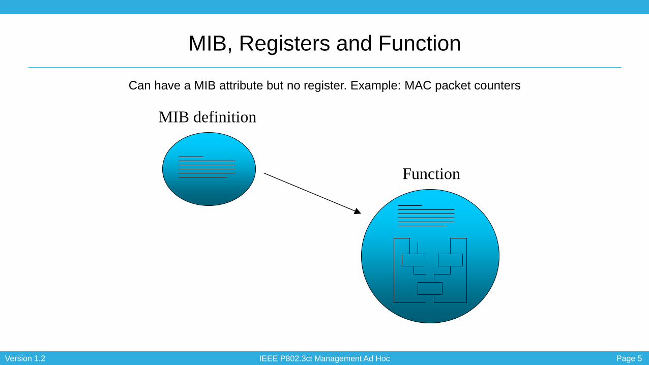
MIB, Registers and Function
Can have a MIB attribute but no register. Example: MAC packet counters
MIB definition
Function
IEEE P802.3ct Management Ad Hoc Page 6Version 1.2
Examples
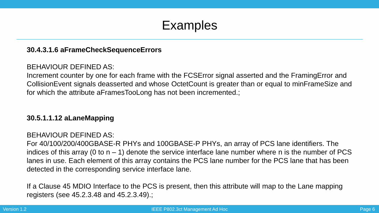
30.4.3.1.6 aFrameCheckSequenceErrors
BEHAVIOUR DEFINED AS:
Increment counter by one for each frame with the FCSError signal asserted and the FramingError and
CollisionEvent signals deasserted and whose OctetCount is greater than or equal to minFrameSize and
for which the attribute aFramesTooLong has not been incremented.;
30.5.1.1.12 aLaneMapping
BEHAVIOUR DEFINED AS:
For 40/100/200/400GBASE-R PHYs and 100GBASE-P PHYs, an array of PCS lane identifiers. The
indices of this array (0 to n – 1) denote the service interface lane number where n is the number of PCS
lanes in use. Each element of this array contains the PCS lane number for the PCS lane that has been
detected in the corresponding service interface lane.
If a Clause 45 MDIO Interface to the PCS is present, then this attribute will map to the Lane mapping
registers (see 45.2.3.48 and 45.2.3.49).;
IEEE P802.3ct Management Ad Hoc Page 7Version 1.2
PMA
PMD
MAC
RS
xMII
MDI
PCS
PMA
MAC
PLS
AUI
MDIPHYSICAL
DATA LINK
NETWORK
TRANSPORT
SESSION
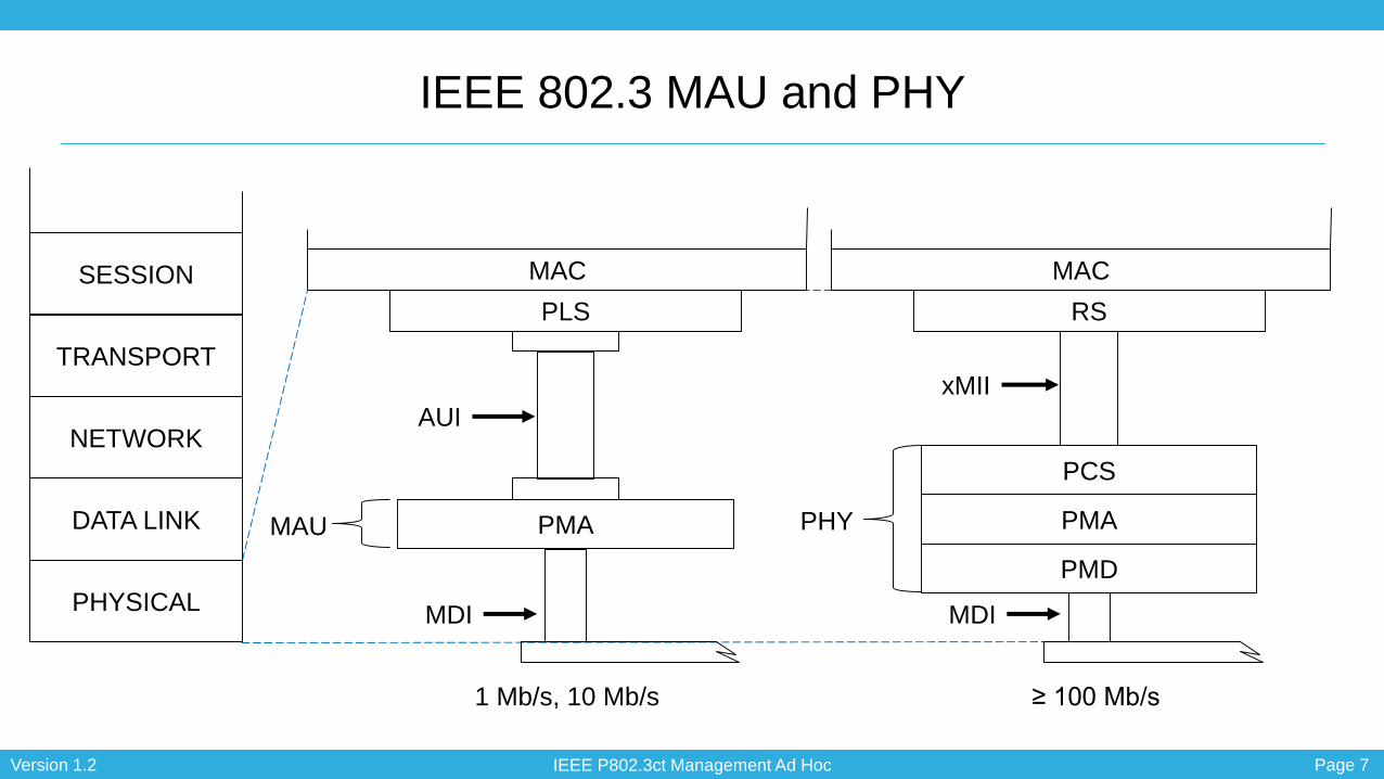
1 Mb/s, 10 Mb/s ≥ 100 Mb/s
PHYMAU
IEEE 802.3 MAU and PHY
IEEE P802.3ct Management Ad Hoc Page 8Version 1.2
MAU managed object class
• 30.5 Layer management for medium attachment units (MAUs)
• 30.5.1 MAU managed object class
• This subclause formally defines the behaviours for the oMAU managed object
class, attributes, actions, and notifications.
• The sublayer that connects directly to the media is called MAU for 10 Mb/s
operation and its equivalent is the combined PMA and PMD sublayers at higher
operating speeds. Because this clause defines management for use at many
speeds, it needs to be able to refer to MAUs and the PMA and PMD sublayers
as a group. Therefore in this clause, the term MAU will include PMA and PMD
sublayers, as well as MAUs, except in those instances where it is explicitly
restricted to 10 Mb/s.
IEEE P802.3ct Management Ad Hoc Page 9Version 1.2
PMA
PMD
MAC
RS
xMII
MDI
PCS
PMA
MAC
PLS
AUI
MDI
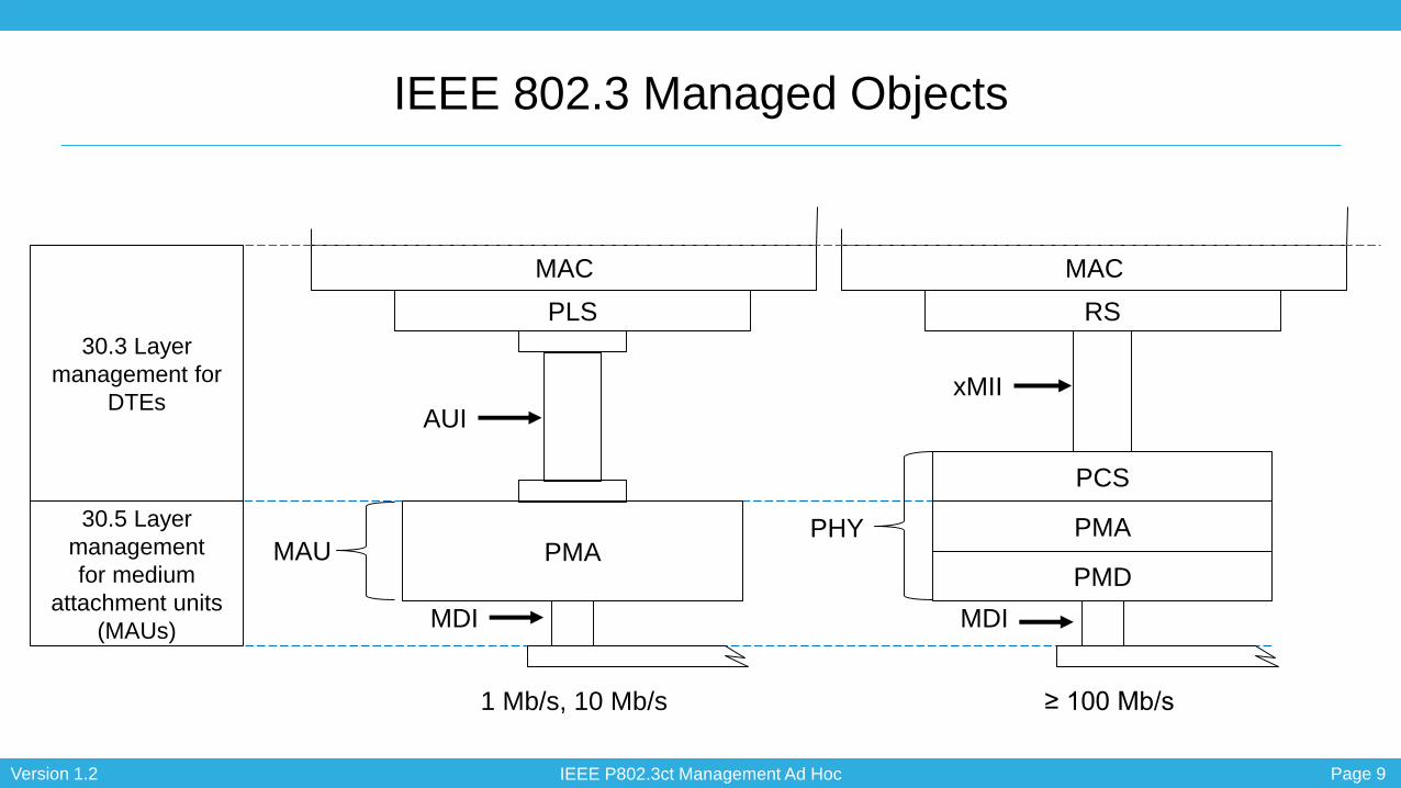
30.5 Layer
management
for medium
attachment units
(MAUs)
30.3 Layer
management for
DTEs
1 Mb/s, 10 Mb/s ≥ 100 Mb/s
PHYMAU
IEEE 802.3 Managed Objects

IEEE P802.3ct Management Ad Hoc Page 10Version 1.2
30.3 DTE
Basic Package (mandatory)
Mandatory Package (mandatory)
Recommended Package (optional)
Optional Package (optional)
Array Package (optional)
Excessive Deferral Package (optional)
Multiple PHY Package (optional)
PHY Error Monitor Capability (optional)
30.4 Repeater
Basic Control Capability (mandatory)
Performance Monitor Capability (optional)
Address Tracking Capability (optional)
100/1000 Mb/s Monitor Capability (optional)
1000 Mb/s Burst Monitor Capability (optional)
30.5 MAU
Basic Package (mandatory)
MAU Control Package (optional)
Media Loss Tracking Package (conditional)
Broadband DTE MAU Package (conditional)
MII Capability (conditional)
PHY Error Monitor Capability (optional)
MultiGBASE-T Operating Margin package (conditional)
Forward Error Correction Package (conditional)
Energy-Efficient Ethernet (optional)

IEEE P802.3ct Management Ad Hoc Page 11Version 1.2
DTE
Basic Package (mandatory)
Mandatory Package (mandatory)
Recommended Package (optional)
Optional Package (optional)
Array Package (optional)
Excessive Deferral Package (optional)
Multiple PHY Package (optional)
PHY Error Monitor Capability (optional)
Energy-Efficient Ethernet (optional)
Repeater
Basic Control Capability (mandatory)
Performance Monitor Capability (optional)
Address Tracking Capability (optional)
100/1000 Mb/s Monitor Capability (optional)
1000 Mb/s Burst Monitor Capability (optional)
MAU
Basic Package (mandatory)
MAU Control Package (optional)
Media Loss Tracking Package (conditional)
Broadband DTE MAU Package (conditional)
MII Capability (conditional)
PHY Error Monitor Capability (optional)
MultiGBASE-T Operating Margin package (conditional)
Forward Error Correction Package (conditional)
Energy-Efficient Ethernet (optional)
IEEE P802.3ct Management Ad Hoc Page 12Version 1.2
DTE
Basic Package (mandatory)
Mandatory Package (mandatory)
Recommended Package (optional)
Optional Package (optional)
Array Package (optional)
Excessive Deferral Package (optional)
Multiple PHY Package (optional)
PHY Error Monitor Capability (optional)
Energy-Efficient Ethernet (optional)
Basic Package (mandatory)
aResourceTypeID
aResourceInfo
oMACEntity
PHY Error Monitor Capability (optional)
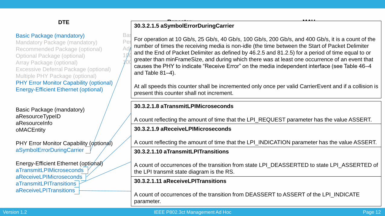
aSymbolErrorDuringCarrier
Energy-Efficient Ethernet (optional)
aTransmitLPIMicroseconds
aReceiveLPIMicroseconds
aTransmitLPITransitions
aReceiveLPITransitions
Repeater
Basic Control Capability (mandatory)
Performance Monitor Capability (optional)
Address Tracking Capability (optional)
100/1000 Mb/s Monitor Capability (optional)
1000 Mb/s Burst Monitor Capability (optional)
MAU
Basic Package (mandatory)
MAU Control Package (optional)
Media Loss Tracking Package (conditional)
Broadband DTE MAU Package (conditional)
MII Capability (conditional)
PHY Error Monitor Capability (optional)
MultiGBASE-T Operating Margin package (conditional)
Forward Error Correction Package (conditional)
Energy-Efficient Ethernet (optional)
30.3.2.1.5 aSymbolErrorDuringCarrier
For operation at 10 Gb/s, 25 Gb/s, 40 Gb/s, 100 Gb/s, 200 Gb/s, and 400 Gb/s, it is a count of the
number of times the receiving media is non-idle (the time between the Start of Packet Delimiter
and the End of Packet Delimiter as defined by 46.2.5 and 81.2.5) for a period of time equal to or
greater than minFrameSize, and during which there was at least one occurrence of an event that
causes the PHY to indicate “Receive Error” on the media independent interface (see Table 46–4
and Table 81–4).
At all speeds this counter shall be incremented only once per valid CarrierEvent and if a collision is
present this counter shall not increment.
30.3.2.1.8 aTransmitLPIMicroseconds
A count reflecting the amount of time that the LPI_REQUEST parameter has the value ASSERT.
30.3.2.1.11 aReceiveLPITransitions
A count of occurrences of the transition from DEASSERT to ASSERT of the LPI_INDICATE
parameter.
30.3.2.1.10 aTransmitLPITransitions
A count of occurrences of the transition from state LPI_DEASSERTED to state LPI_ASSERTED of
the LPI transmit state diagram is the RS.
30.3.2.1.9 aReceiveLPIMicroseconds
A count reflecting the amount of time that the LPI_INDICATION parameter has the value ASSERT.

IEEE P802.3ct Management Ad Hoc Page 13Version 1.2
DTE
Basic Package (mandatory)
Mandatory Package (mandatory)
Recommended Package (optional)
Optional Package (optional)
Array Package (optional)
Excessive Deferral Package (optional)
Multiple PHY Package (optional)
PHY Error Monitor Capability (optional)
Energy-Efficient Ethernet (optional)
Repeater
Basic Control Capability (mandatory)
Performance Monitor Capability (optional)
Address Tracking Capability (optional)
100/1000 Mb/s Monitor Capability (optional)
1000 Mb/s Burst Monitor Capability (optional)
MAU
Basic Package (mandatory)
MAU Control Package (optional)
Media Loss Tracking Package (conditional)
Broadband DTE MAU Package (conditional)
MII Capability (conditional)
PHY Error Monitor Capability (optional)
MultiGBASE-T Operating Margin package (conditional)
Forward Error Correction Package (conditional)
Energy-Efficient Ethernet (optional)
Basic Package (mandatory)
aResourceTypeID
aResourceInfo
aMAUID
aMAUType
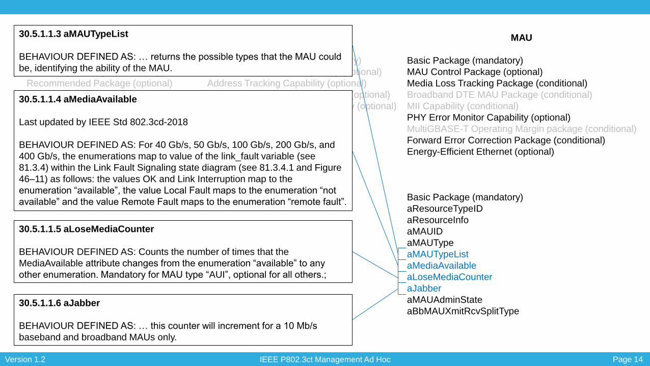
aMAUTypeList
aMediaAvailable
aLoseMediaCounter
aJabber
aMAUAdminState
aBbMAUXmitRcvSplitType
IEEE P802.3ct:
30.5.1.1.2 aMAUType
Insert 100GBASE-ZR PHY type into the “APPROPRIATE SYNTAX” section of
30.5.1.1.2 after 100GBASE-ER4 as follows:
APPROPRIATE SYNTAX:
100GBASE-ZR 100GBASE-R PCS/100GBASE-ZR PMA over a DWDM
system PMD with reach up to at least 80 km as specified in
Clause 154
30.3.2.1.2 aPhyType
APPROPRIATE SYNTAX:
40GBASE-T Clause 113 40 Gb/s DSQ128
100GBASE-R Clause 82 100 Gb/s multi-PCS lane using 2-level PAM
100GBASE-P Clause 82 100 Gb/s multi-PCS lane using >2-level PAM
200GBASE-R Clause 119 200 Gb/s multi-PCS lane 64B/66B
Comment: Perhaps 100GBASE-R should be updated to ‘Clause 82 100 Gb/s
multi-PCS lane 64B/66B’ since (1) the title of Clause 82 is ‘Physical Coding
Sublayer (PCS) for 64B/66B, type 40GBASE-R and 100GBASE-R’ and (2) it is
a PCS that doesn’t specify the signaling.
IEEE P802.3ct Management Ad Hoc Page 14Version 1.2
DTE
Basic Package (mandatory)
Mandatory Package (mandatory)
Recommended Package (optional)
Optional Package (optional)
Array Package (optional)
Excessive Deferral Package (optional)
Multiple PHY Package (optional)
PHY Error Monitor Capability (optional)
Energy-Efficient Ethernet (optional)
Repeater
Basic Control Capability (mandatory)
Performance Monitor Capability (optional)
Address Tracking Capability (optional)
100/1000 Mb/s Monitor Capability (optional)
1000 Mb/s Burst Monitor Capability (optional)
MAU
Basic Package (mandatory)
MAU Control Package (optional)
Media Loss Tracking Package (conditional)
Broadband DTE MAU Package (conditional)
MII Capability (conditional)
PHY Error Monitor Capability (optional)
MultiGBASE-T Operating Margin package (conditional)
Forward Error Correction Package (conditional)
Energy-Efficient Ethernet (optional)
Basic Package (mandatory)
aResourceTypeID
aResourceInfo
aMAUID
aMAUType
aMAUTypeList
aMediaAvailable
aLoseMediaCounter
aJabber
aMAUAdminState
aBbMAUXmitRcvSplitType
30.5.1.1.3 aMAUTypeList
BEHAVIOUR DEFINED AS: … returns the possible types that the MAU could
be, identifying the ability of the MAU.
30.5.1.1.4 aMediaAvailable
Last updated by IEEE Std 802.3cd-2018
BEHAVIOUR DEFINED AS: For 40 Gb/s, 50 Gb/s, 100 Gb/s, 200 Gb/s, and
400 Gb/s, the enumerations map to value of the link_fault variable (see
81.3.4) within the Link Fault Signaling state diagram (see 81.3.4.1 and Figure
46–11) as follows: the values OK and Link Interruption map to the
enumeration “available”, the value Local Fault maps to the enumeration “not
available” and the value Remote Fault maps to the enumeration “remote fault”.
30.5.1.1.5 aLoseMediaCounter
BEHAVIOUR DEFINED AS: Counts the number of times that the
MediaAvailable attribute changes from the enumeration “available” to any
other enumeration. Mandatory for MAU type “AUI”, optional for all others.;
30.5.1.1.6 aJabber
BEHAVIOUR DEFINED AS: … this counter will increment for a 10 Mb/s
baseband and broadband MAUs only.

IEEE P802.3ct Management Ad Hoc Page 15Version 1.2
DTE
Basic Package (mandatory)
Mandatory Package (mandatory)
Recommended Package (optional)
Optional Package (optional)
Array Package (optional)
Excessive Deferral Package (optional)
Multiple PHY Package (optional)
PHY Error Monitor Capability (optional)
Energy-Efficient Ethernet (optional)
Repeater
Basic Control Capability (mandatory)
Performance Monitor Capability (optional)
Address Tracking Capability (optional)
100/1000 Mb/s Monitor Capability (optional)
1000 Mb/s Burst Monitor Capability (optional)
MAU
Basic Package (mandatory)
MAU Control Package (optional)
Media Loss Tracking Package (conditional)
Broadband DTE MAU Package (conditional)
MII Capability (conditional)
PHY Error Monitor Capability (optional)
MultiGBASE-T Operating Margin package (conditional)
Forward Error Correction Package (conditional)
Energy-Efficient Ethernet (optional)
Basic Package (mandatory)
aResourceTypeID
aResourceInfo
aMAUID
aMAUType
aMAUTypeList
aMediaAvailable
aLoseMediaCounter
aJabber
aMAUAdminState
aBbMAUXmitRcvSplitType
30.5.1.1.7 aMAUAdminState
BEHAVIOUR DEFINED AS: A MAU in management state “standby” forces DI
and CI to idle and the media transmitter to idle or fault, if supported. The
management state “standby” only applies to link type MAUs. The state
of MediaAvailable is unaffected. A MAU or AUI in …
30.5.1.1.8 aBbMAUXmitRcvSplitType
BEHAVIOUR DEFINED AS: Returns a value that indicates the type of
frequency multiplexing/cabling system used to separate the transmit and
receive paths for the.

IEEE P802.3ct Management Ad Hoc Page 16Version 1.2
DTE
Basic Package (mandatory)
Mandatory Package (mandatory)
Recommended Package (optional)
Optional Package (optional)
Array Package (optional)
Excessive Deferral Package (optional)
Multiple PHY Package (optional)
PHY Error Monitor Capability (optional)
Energy-Efficient Ethernet (optional)
Repeater
Basic Control Capability (mandatory)
Performance Monitor Capability (optional)
Address Tracking Capability (optional)
100/1000 Mb/s Monitor Capability (optional)
1000 Mb/s Burst Monitor Capability (optional)
MAU
Basic Package (mandatory)
MAU Control Package (optional)
Media Loss Tracking Package (conditional)
Broadband DTE MAU Package (conditional)
MII Capability (conditional)
PHY Error Monitor Capability (optional)
MultiGBASE-T Operating Margin package (conditional)
Forward Error Correction Package (conditional)
Energy-Efficient Ethernet (optional)
Media Loss Tracking Package (conditional)
aLoseMediaCounter
Energy-Efficient Ethernet (optional)
aLDFastRetrainCount
aLPFastRetrainCount
20.2.2.1.4 aLoseMediaCounter
BEHAVIOUR DEFINED AS: Counts the number of times that the MAU leaves
MediaAvailState “available.” Mandatory for MAU type “AUI,” optional for all
others.
30.5.1.1.24 aLDFastRetrainCount
BEHAVIOUR DEFINED AS: A count of the number of fast retrains initiated by
the local device.
30.5.1.1.25 aLPFastRetrainCount
BEHAVIOUR DEFINED AS: count of the number of fast retrains initiated by
the link partner.

IEEE P802.3ct Management Ad Hoc Page 17Version 1.2
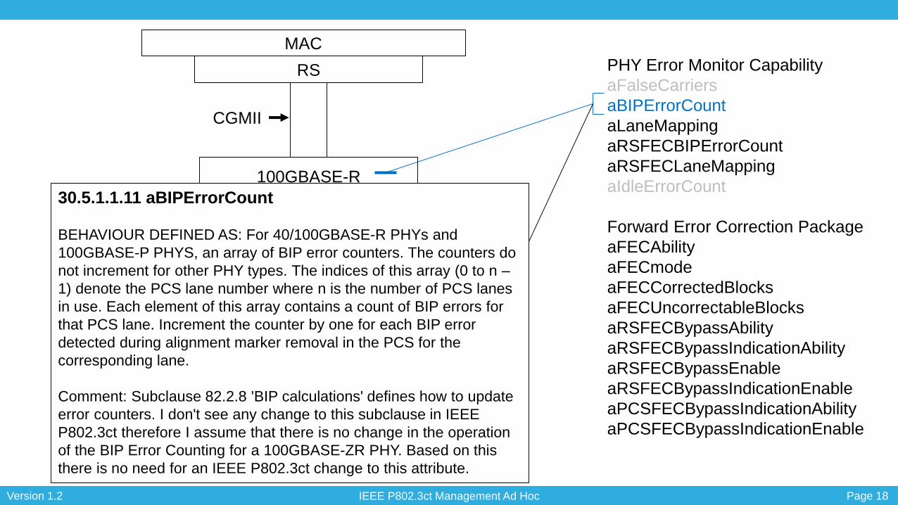
PHY Error Monitor Capability
aFalseCarriers
aBIPErrorCount
aLaneMapping
aRSFECBIPErrorCount
aRSFECLaneMapping
aIdleErrorCount
Forward Error Correction Package
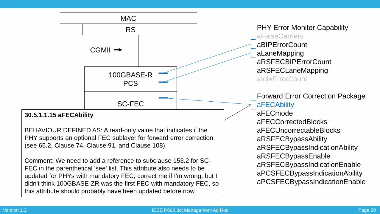
aFECAbility
aFECmode
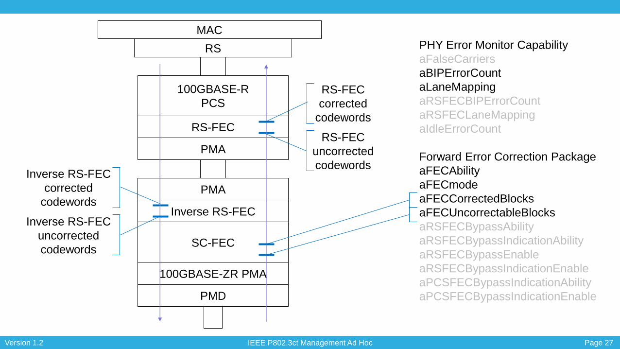
aFECCorrectedBlocks
aFECUncorrectableBlocks
aRSFECBypassAbility
aRSFECBypassIndicationAbility
aRSFECBypassEnable
aRSFECBypassIndicationEnable
aPCSFECBypassIndicationAbility
aPCSFECBypassIndicationEnable
30.5.1.1.10 aFalseCarriers
BEHAVIOUR DEFINED AS: A count of the number of false carrier
events during IDLE in 100BASE-X and 1000BASE-X links.
Comment: No need for an IEEE P802.3ct change to this attribute, this
only applies to 100BASE-X and 1000BASE-X links.
30.5.1.1.13 aIdleErrorCount
BEHAVIOUR DEFINED AS: This attribute takes the eight-bit value
from the 100BASE-T2 Status register (MII management register 10)
bits 7:0 “Idle Error Count” as described in 100BASE-T2, 32.5.3.2.6
and 40.5.
Comment: No need for an IEEE P802.3ct change to this attribute, this
only applies to 100BASE-T2 links.
IEEE P802.3ct Management Ad Hoc Page 18Version 1.2
PHY Error Monitor Capability
aFalseCarriers
aBIPErrorCount
aLaneMapping
aRSFECBIPErrorCount
aRSFECLaneMapping
aIdleErrorCount
Forward Error Correction Package
aFECAbility
aFECmode
aFECCorrectedBlocks
aFECUncorrectableBlocks
aRSFECBypassAbility
aRSFECBypassIndicationAbility
aRSFECBypassEnable
aRSFECBypassIndicationEnable
aPCSFECBypassIndicationAbility
aPCSFECBypassIndicationEnable
100GBASE-R
PCS
SC-FEC
100GBASE-ZR PMA
PMD
MAC
30.5.1.1.11 aBIPErrorCount
BEHAVIOUR DEFINED AS: For 40/100GBASE-R PHYs and
100GBASE-P PHYS, an array of BIP error counters. The counters do
not increment for other PHY types. The indices of this array (0 to n –
1) denote the PCS lane number where n is the number of PCS lanes
in use. Each element of this array contains a count of BIP errors for
that PCS lane. Increment the counter by one for each BIP error
detected during alignment marker removal in the PCS for the
corresponding lane.
Comment: Subclause 82.2.8 'BIP calculations' defines how to update
error counters. I don't see any change to this subclause in IEEE
P802.3ct therefore I assume that there is no change in the operation
of the BIP Error Counting for a 100GBASE-ZR PHY. Based on this
there is no need for an IEEE P802.3ct change to this attribute.
RS
CGMII

IEEE P802.3ct Management Ad Hoc Page 19Version 1.2
PHY Error Monitor Capability
aFalseCarriers
aBIPErrorCount
aLaneMapping
aRSFECBIPErrorCount
aRSFECLaneMapping
aIdleErrorCount
Forward Error Correction Package
aFECAbility
aFECmode
aFECCorrectedBlocks
aFECUncorrectableBlocks
aRSFECBypassAbility
aRSFECBypassIndicationAbility
aRSFECBypassEnable
aRSFECBypassIndicationEnable
aPCSFECBypassIndicationAbility
aPCSFECBypassIndicationEnable
100GBASE-R
PCS
SC-FEC
100GBASE-ZR PMA
PMD
MAC
30.5.1.1.12 aLaneMapping
BEHAVIOUR DEFINED AS: For 40/100/200/400GBASE-R PHYs and
100GBASE-P PHYs, an array of PCS lane identifiers. The indices of
this array (0 to n – 1) denote the service interface lane number where
n is the number of PCS lanes in use. Each element of this array
contains the PCS lane number for the PCS lane that has been
detected in the corresponding service interface lane.
Comment: I don't see any changes in IEEE P802.3ct in relation to
PCS lane mapping described in Clause 82 (for example subclause
82.2.19.3 'State diagrams'). Based on this there is no need for an
IEEE P802.3ct change to this attribute.
RS
CGMII
IEEE P802.3ct Management Ad Hoc Page 20Version 1.2
PHY Error Monitor Capability
aFalseCarriers
aBIPErrorCount
aLaneMapping
aRSFECBIPErrorCount
aRSFECLaneMapping
aIdleErrorCount
Forward Error Correction Package
aFECAbility
aFECmode
aFECCorrectedBlocks
aFECUncorrectableBlocks
aRSFECBypassAbility
aRSFECBypassIndicationAbility
aRSFECBypassEnable
aRSFECBypassIndicationEnable
aPCSFECBypassIndicationAbility
aPCSFECBypassIndicationEnable
100GBASE-R
PCS
SC-FEC
100GBASE-ZR PMA
PMD
MAC
30.5.1.1.15 aFECAbility
BEHAVIOUR DEFINED AS: A read-only value that indicates if the
PHY supports an optional FEC sublayer for forward error correction
(see 65.2, Clause 74, Clause 91, and Clause 108).
Comment: We need to add a reference to subclause 153.2 for SC-
FEC in the parenthetical 'see' list. This attribute also needs to be
updated for PHYs with mandatory FEC, correct me if I'm wrong, but I
didn't think 100GBASE-ZR was the first FEC with mandatory FEC, so
this attribute should probably have been updated before now.
RS
CGMII

IEEE P802.3ct Management Ad Hoc Page 21Version 1.2
PHY Error Monitor Capability
aFalseCarriers
aBIPErrorCount
aLaneMapping
aRSFECBIPErrorCount
aRSFECLaneMapping
aIdleErrorCount
Forward Error Correction Package
aFECAbility
aFECmode
aFECCorrectedBlocks
aFECUncorrectableBlocks
aRSFECBypassAbility
aRSFECBypassIndicationAbility
aRSFECBypassEnable
aRSFECBypassIndicationEnable
aPCSFECBypassIndicationAbility
aPCSFECBypassIndicationEnable
100GBASE-R
PCS
SC-FEC
100GBASE-ZR PMA
PMD
MAC
30.5.1.1.16 aFECmode
BEHAVIOUR DEFINED AS: A read-write value that indicates the
mode of operation of the FEC sublayer for forward error correction
(see 65.2, Clause 74, Clause 91, and Clause 108). A GET operation
returns the current mode of operation of the PHY. A SET operation
changes the mode of operation of the PHY to the indicated value. The
enumerations “BASE-R enabled” and “RS-FEC enabled” are only
used for 25GBASE-CR, 25GBASE-CR-S, 25GBASE-KR, and
25GBASE-KR-S PHYs where operation in the no-FEC mode maps to
the enumerations “disabled”, operation in the BASE-R FEC mode
maps to the enumerations “BASE-R enabled”, and operation in the
RS-FEC mode maps to the enumerations “RS-FEC enabled” (see
110.6 and 111.6).
Comment: Need to add a SC-FEC to the list. We also need to
address mandatory FEC, for example a SET operation where FEC is
mandatory will have no effect.
RS
CGMII

IEEE P802.3ct Management Ad Hoc Page 22Version 1.2
PHY Error Monitor Capability
aFalseCarriers
aBIPErrorCount
aLaneMapping
aRSFECBIPErrorCount
aRSFECLaneMapping
aIdleErrorCount
Forward Error Correction Package
aFECAbility
aFECmode
aFECCorrectedBlocks
aFECUncorrectableBlocks
aRSFECBypassAbility
aRSFECBypassIndicationAbility
aRSFECBypassEnable
aRSFECBypassIndicationEnable
aPCSFECBypassIndicationAbility
aPCSFECBypassIndicationEnable
100GBASE-R
PCS
SC-FEC
100GBASE-ZR PMA
PMD
RS
MAC30.5.1.1.17 aFECCorrectedBlocks
BEHAVIOUR DEFINED AS: For 1000BASE-PX,
10/25/40/50/100/200/400GBASE-R, 100GBASE-P, 10GBASE-PR, or
10/1GBASE-PRX PHYs, an array of corrected FEC block counters. The
counters do not increment for other PHY types. The indices of this array (0 to N
– 1) denote the FEC sublayer instance number where N is the number of FEC
sublayer instances in use. The number of FEC sublayer instances in use is set
to one for PHYs that do not use PCS lanes or use a single FEC instance for all
lanes. Each element of this array contains a count of corrected FEC blocks for
that FEC sublayer instance. Increment the counter by one for each received
block that is corrected by the FEC function in the PHY for the corresponding
lane or FEC sublayer instance. If a Clause 45 MDIO Interface is present, then
this attribute maps to the FEC corrected blocks counter(s) (see 45.2.10.5 and
45.2.1.103 for 10GBASE-R, 45.2.3.41 for 10GBASE-PR and 10/1GBASE-PRX,
45.2.1.125 for BASE-R, 45.2.1.112 for RS-FEC, and 45.2.3.61 for PCS FEC).
Note: Last updated by IEEE Std 802.3cd-2018.
Comment: This behaviour mentions FEC sublayer instances, but this is in
reference to the number of lanes and says '... set to one for PHYs that do not
use PCS lanes or use a single FEC instance for all lanes.'. I believe the latter
part of the quoted text covers SC-FEC which is a single instance for all lanes
(Figure 153–2). Based on this I think the only update needed is to the Clause 45
list to add a reference to subclause 45.2.1.186al 'SC-FEC corrected codewords
counter (Register 1.2276, 1.2277)' added by IEEE P802.3ct for 100GBASE-ZR.
In addition I didn’t think all 10/25/40/50/100/200/400GBASE-R PHYs support
FEC, so perhaps this needs to be qualified with ‘that support FEC’.

IEEE P802.3ct Management Ad Hoc Page 23Version 1.2
PHY Error Monitor Capability
aFalseCarriers
aBIPErrorCount
aLaneMapping
aRSFECBIPErrorCount
aRSFECLaneMapping
aIdleErrorCount
Forward Error Correction Package
aFECAbility
aFECmode
aFECCorrectedBlocks
aFECUncorrectableBlocks
aRSFECBypassAbility
aRSFECBypassIndicationAbility
aRSFECBypassEnable
aRSFECBypassIndicationEnable
aPCSFECBypassIndicationAbility
aPCSFECBypassIndicationEnable
100GBASE-R
PCS
SC-FEC
100GBASE-ZR PMA
PMD
MAC
RS
CGMII
MDI
30.5.1.1.18 aFECUncorrectableBlocks
BEHAVIOUR DEFINED AS: For 1000BASE-PX,
10/25/40/50/100/200/400GBASE-R, 100GBASE-P, 10GBASE-PR, or
10/1GBASE-PRX PHYs, an array of uncorrectable FEC block counters. The
counters do not increment for other PHY types. The indices of this array (0 to N
– 1) denote the FEC sublayer instance number where N is the number of FEC
sublayer instances in use. The number of FEC sublayer instances in use is set
to one for PHYs that do not use PCS lanes or use a single FEC instance for all
lanes. Each element of this array contains a count of uncorrectable FEC blocks
for that FEC sublayer instance. Increment the counter by one for each FEC
block that is determined to be uncorrectable by the FEC function in the PHY for
the corresponding lane or FEC sublayer instance. If a Clause 45 MDIO Interface
is present, then this attribute maps to the FEC uncorrectable blocks counter(s)
(see 45.2.10.6 and 45.2.1.104 for 10GBASE-R, 45.2.3.42 for 10GBASE-PR and
10/ 1GBASE-PRX, 45.2.1.133 for BASE-R, 45.2.1.113 for RS-FEC, and
45.2.3.62 for PCS FEC).
Note: Last updated by IEEE Std 802.3cd-2018.
My comment: Same as aFECUncorrectableBlocks, but reference will be to
subclause 45.2.1.186am 'SC-FEC uncorrected codewords counter (Register
1.2278, 1.2279)' added by IEEE P802.3ct for 100GBASE-ZR.
In addition I didn’t think all 10/25/40/50/100/200/400GBASE-R PHYs support
FEC, so perhaps this needs to be qualified with ‘that support FEC’.

IEEE P802.3ct Management Ad Hoc Page 24Version 1.2
PHY Error Monitor Capability
aFalseCarriers
aBIPErrorCount
aLaneMapping
aRSFECBIPErrorCount
aRSFECLaneMapping
aIdleErrorCount
Forward Error Correction Package
aFECAbility
aFECmode
aFECCorrectedBlocks
aFECUncorrectableBlocks
aRSFECBypassAbility
aRSFECBypassIndicationAbility
aRSFECBypassEnable
aRSFECBypassIndicationEnable
aPCSFECBypassIndicationAbility
aPCSFECBypassIndicationEnable
100GBASE-R
PCS
SC-FEC
100GBASE-ZR PMA
PMD
MAC
RS
CGMII
MDI
All these attributes only apply to RS-FEC, and since the
100GBASE-ZR 'line side' FEC is SC-FEC, these attributes are
not applicable. We perhaps need to clarify that all these
attributes apply to the 'line side' FECnow that there can be up
to three FECs in a PHY.

IEEE P802.3ct Management Ad Hoc Page 25Version 1.2
PHY Error Monitor Capability
aFalseCarriers
aBIPErrorCount
aLaneMapping
aRSFECBIPErrorCount
aRSFECLaneMapping
aIdleErrorCount
Forward Error Correction Package
aFECAbility
aFECmode
aFECCorrectedBlocks
aFECUncorrectableBlocks
aRSFECBypassAbility
aRSFECBypassIndicationAbility
aRSFECBypassEnable
aRSFECBypassIndicationEnable
aPCSFECBypassIndicationAbility
aPCSFECBypassIndicationEnable
100GBASE-R
PCS
SC-FEC
100GBASE-ZR PMA
PMD
MAC
RS
CGMII
MDI

IEEE P802.3ct Management Ad Hoc Page 26Version 1.2
PHY Error Monitor Capability
aFalseCarriers
aBIPErrorCount
aLaneMapping
aRSFECBIPErrorCount
aRSFECLaneMapping
aIdleErrorCount
Forward Error Correction Package
aFECAbility
aFECmode
aFECCorrectedBlocks
aFECUncorrectableBlocks
aRSFECBypassAbility
aRSFECBypassIndicationAbility
aRSFECBypassEnable
aRSFECBypassIndicationEnable
aPCSFECBypassIndicationAbility
aPCSFECBypassIndicationEnable
100GBASE-R
PCS
SC-FEC
100GBASE-ZR PMA
PMD
RS
MAC
RS-FEC
PMA
PMA
Inverse RS-FEC
CGMII
MDI
100GAUI-n
IEEE P802.3ct Management Ad Hoc Page 27Version 1.2
PHY Error Monitor Capability
aFalseCarriers
aBIPErrorCount
aLaneMapping
aRSFECBIPErrorCount
aRSFECLaneMapping
aIdleErrorCount
Forward Error Correction Package
aFECAbility
aFECmode
aFECCorrectedBlocks
aFECUncorrectableBlocks
aRSFECBypassAbility
aRSFECBypassIndicationAbility
aRSFECBypassEnable
aRSFECBypassIndicationEnable
aPCSFECBypassIndicationAbility
aPCSFECBypassIndicationEnable
100GBASE-R
PCS
SC-FEC
100GBASE-ZR PMA
PMD
RS
MAC
RS-FEC
PMA
PMA
Inverse RS-FEC
Inverse RS-FEC
corrected
codewords
Inverse RS-FEC
uncorrected
codewords
RS-FEC
corrected
codewords
RS-FEC
uncorrected
codewords

IEEE P802.3ct Management Ad Hoc Page 28Version 1.2
Thank you


