Abstract—Smart antenna and associated technologies are ex-pected to play a significant role in enabling broadband wirelesscommunication systems. Smart antennas exploit space diversity tohelp provide high data rates, increased channel capacity, and im-proved quality of service at an affordable cost. In this paper wepresent a new procedure for implementing smart antenna algo-rithms. It is a hybrid approach that integrates the features of theswitched beam method and the adaptive beam forming approach.Specifically it is shown that by using high gain antenna elementsand combining the switched beam process with the adaptive beam
forming procedure on a limited number of elements (as low astwo in an eight-element array), a performance close to that of amore complex eight-element adaptive array may be achieved. Theproposed hybrid method, therefore, is fast, is computationally ef-ficient, and provides a cost effective approach for exploiting spacediversity. Even with the inclusion of interference signals, the pro-posed hybrid approach out-performed the switched beam method,andprovidedperformance similar to that of an adaptive array withless number of elements (three in an eight-element array). Imple-mentation of an adaptive array also includes estimations; hence,reducing the number of elements in an array may lead to improvedaccuracy, in addition to fast convergence and reduced complexity.
2928 IEEE TRANSACTIONS ON ANTENNAS AND PROPAGATION, VOL. 51, NO. 10, OCTOBER 2003
Fig. 3. Switched-beam smart antenna system diagram.
Fig. 4. Pattern of switched-beam smart antenna. Desired signals and interferences denoted by solid and dashed arrows, respectively.
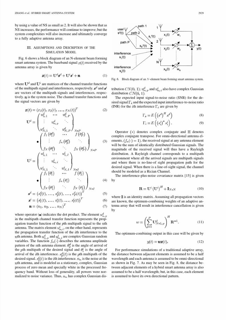
Fig. 5. Proposed hybrid smart antenna system. antenna elements are used to receive signals. The beam-forming process is performed on a smaller number( ) of signals.
streams on the data bus. Considering the slow angle move-
ment of mobile users and the relatively wide beamwidth of the
radiation pattern of antenna elements, the to switches do
not need to be updated in real time. It will be shown that in most
cases when using the arrangement in Fig. 5, performance sim-
ilar to that of an eight-element adaptive system can be achieved
2930 IEEE TRANSACTIONS ON ANTENNAS AND PROPAGATION, VOL. 51, NO. 10, OCTOBER 2003
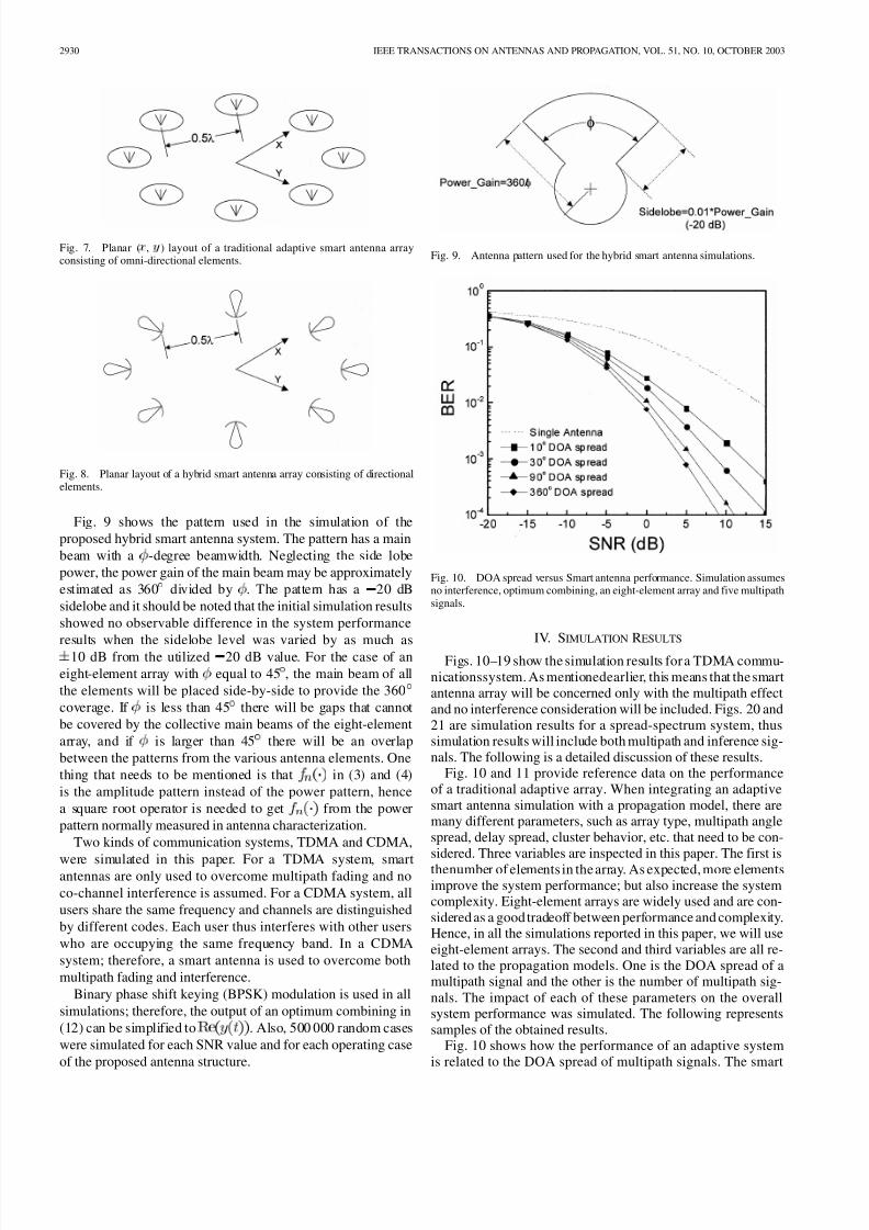
Fig. 7. Planar ( , ) layout of a traditional adaptive smart antenna arrayconsisting of omni-directional elements.
Fig. 8. Planar layout of a hybrid smart antenna array consisting of directionalelements.
Fig. 9 shows the pattern used in the simulation of the
proposed hybrid smart antenna system. The pattern has a main
beam with a -degree beamwidth. Neglecting the side lobe
power, the power gain of the main beam may be approximately
estimated as 360 divided by . The pattern has a 20 dB
sidelobe and it should be noted that the initial simulation results
showed no observable difference in the system performance
results when the sidelobe level was varied by as much as10 dB from the utilized 20 dB value. For the case of an
eight-element array with equal to 45 , the main beam of all
the elements will be placed side-by-side to provide the 360
coverage. If is less than 45 there will be gaps that cannot
be covered by the collective main beams of the eight-element
array, and if is larger than 45 there will be an overlap
between the patterns from the various antenna elements. One
thing that needs to be mentioned is that in (3) and (4)
is the amplitude pattern instead of the power pattern, hence
a square root operator is needed to get from the power
pattern normally measured in antenna characterization.
Two kinds of communication systems, TDMA and CDMA,
were simulated in this paper. For a TDMA system, smartantennas are only used to overcome multipath fading and no
co-channel interference is assumed. For a CDMA system, all
users share the same frequency and channels are distinguished
by different codes. Each user thus interferes with other users
who are occupying the same frequency band. In a CDMA
system; therefore, a smart antenna is used to overcome both
multipath fading and interference.
Binary phase shift keying (BPSK) modulation is used in all
simulations; therefore, the output of an optimum combining in
(12) can be simplified to . Also, 500 000 random cases
were simulated for each SNR value and for each operating case
of the proposed antenna structure.
Fig. 9. Antenna pattern used for the hybrid smart antenna simulations.
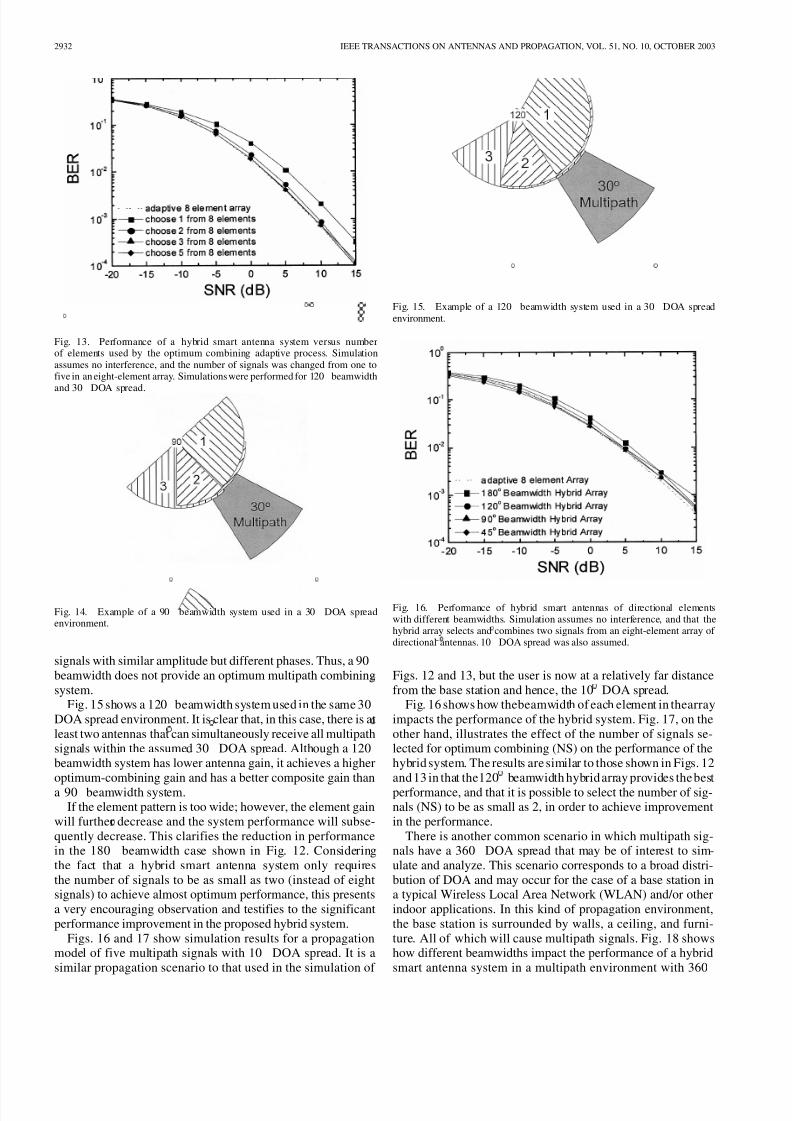
Fig. 10. DOA spread versus Smart antenna performance. Simulation assumesno interference, optimum combining, an eight-element array and five multipathsignals.
IV. SIMULATION RESULTS
Figs. 10–19 show the simulation results for a TDMA commu-nicationssystem. As mentionedearlier, this means that the smartantenna array will be concerned only with the multipath effectand no interference consideration will be included. Figs. 20 and21 are simulation results for a spread-spectrum system, thussimulation results will include both multipath and inference sig-nals. The following is a detailed discussion of these results.
Fig. 10 and 11 provide reference data on the performanceof a traditional adaptive array. When integrating an adaptivesmart antenna simulation with a propagation model, there aremany different parameters, such as array type, multipath anglespread, delay spread, cluster behavior, etc. that need to be con-sidered. Three variables are inspected in this paper. The first isthenumber of elements in the array. As expected, more elementsimprove the system performance; but also increase the systemcomplexity. Eight-element arrays are widely used and are con-sidered as a good tradeoff between performance and complexity.Hence, in all the simulations reported in this paper, we will useeight-element arrays. The second and third variables are all re-lated to the propagation models. One is the DOA spread of amultipath signal and the other is the number of multipath sig-nals. The impact of each of these parameters on the overallsystem performance was simulated. The following representssamples of the obtained results.
Fig. 10 shows how the performance of an adaptive systemis related to the DOA spread of multipath signals. The smart
Fig. 11. Multipath number versus Smart antenna performance. Simulationassumes no interference, optimum combining, an eight-element array and 30DOA spread.
antenna used in this simulation is a traditional optimum-com-bining adaptive array with eight omni-directional elements. Itwas assumed that there were five Gaussian multipath signals.The axis is the SNR at each antenna element and the axisis the bit error rate (BER) of coherent demodulation of BPSK atthe array output. It is clear that when the DOA spread of mul-tipath signals decreases from 360 to 10 , the system perfor-mance decreases and the SNR required for keeping BER lessthan 10 has to increase by 7.8 dB, from 4.4 to 12.2 dB. TheBER result of a single antenna is also shown as reference by thedotted line in the same figure. This can be explained in terms of the fact that when DOA decreases, multipath signals becomemore correlated; and hence, cause a decrease in the adaptivearray performance.
Fig. 11 shows the impact of the number of multipath on theperformance of an adaptive antenna system. The simulatedsystem is also a traditional optimum-combining array with 8omni-directional elements, and the multipath DOA spread wasselected in this case to be 30 . Results in Fig. 11 show that asthe number of multipath increases from 2 to 12, the systemperformance increases and the SNR required for keepingBER less than 10 is decreased from 17.1 to 6.9 dB. Thisimproved performance can be explained in terms of the reducedcorrelation of the signals at each antenna due to the richermultipath environment.
For the proposed hybrid smart antenna system, there are fivevariables that need to be inspected in the simulations. Besidesthe three variables mentioned above (number of elements,number of multipath, and DOA spread) which are sharedwith an adaptive smart antenna system, there are two morevariables that need to be considered in this case. These includebeamwidth of the directional antenna element and the numberof elements that will be chosen for the beamforming process( in Fig. 5). Simulation results show that the first three vari-ables have similar impact on the performance of the proposedhybrid smart antenna design when compared with the adaptivesmart antenna system described above. Thus, only the effect of the last two parameters will be presented and discussed here.
Fig. 12. Performance of a hybrid smart antenna system as a function of thebeamwidth of the directional elements. Simulation assumes no interference andthat the hybrid array selects and combines two signals from an array of eightelements of directional antennas. 30 DOA spread was assumed.
The propagation model used in the simulations in bothFigs. 12 and 13 includes five multipath signals with 30 DOAspread. This 30 DOA spread corresponds to a propagationscenario for a base station that is installed on top of a buildingroof where the use is at a moderate distance from the basestation. It is assumed that there are no obstacles around the basestation antenna and all multipath signals are caused by clusterreflections around the user.
Fig. 12 inspects how a differentantenna beamwidth impactstheperformance of theproposedhybrid smartantenna system. Adifferent beamwidth also means a different gain because the ele-ment gain is assumed to be (see Fig. 9 and neglecting the
side lobe power). The hybrid smart antenna used in this simula-tion selects and combines the two largest signals ( ) outof theavailable ones from thearrayof eight elements. Thedottedline in Fig. 12 shows the results of a traditional adaptive smartantenna method (optimum-combining eight elements) and is in-cluded here for reference.
From Fig. 12, it is interesting to note that the 120 beamwidthhybrid array has the best performance, more specifically, thatthe required SNR to keep BER less than 10 is only 0.67 dBhigher than that for a traditional adaptive antenna system.
Results in Fig. 13 confirm the expected performance andshow an improved BER with the increase in the number of elements used in the adaptive process. It may also be notedthat results for more than two elements in the proposed hybridsmart antenna array system superpose those for the traditionaladaptive array; hence, the increase in the number of signals isunnecessary and just adds to the complexity of the system.
As discussed earlier, a hybrid system takes advantage of both the antenna gain and optimum combining to improve theoverall system performance. Fig. 14 shows a case where a 90beamwidth system is used in a 30 DOA spread environment.Different amplitudes were only used to clarify the graphicalillustration. All three antennas were assumed to have the samegain. In Fig. 14 the second antenna can receive all multipathsignals, but the first and third antennas can only receive part of these multipath signals. The requirement for an optimum-com-bining array is that each antenna can receive all multipath
2932 IEEE TRANSACTIONS ON ANTENNAS AND PROPAGATION, VOL. 51, NO. 10, OCTOBER 2003
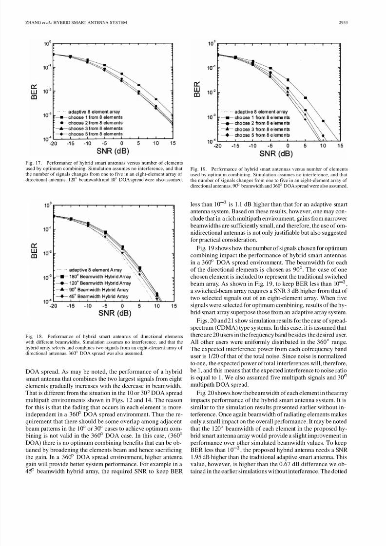
Fig. 13. Performance of a hybrid smart antenna system versus numberof elements used by the optimum combining adaptive process. Simulationassumes no interference, and the number of signals was changed from one tofive in an eight-element array. Simulations were performed for 120 beamwidth
and 30 DOA spread.
Fig. 14. Example of a 90 beamwidth system used in a 30 DOA spreadenvironment.
signals with similar amplitude but different phases. Thus, a 90beamwidth does not provide an optimum multipath combiningsystem.
Fig. 15 shows a 120 beamwidth system used in the same 30DOA spread environment. It is clear that, in this case, there is atleast two antennas that can simultaneously receive all multipathsignals within the assumed 30 DOA spread. Although a 120beamwidth system has lower antenna gain, it achieves a higheroptimum-combining gain and has a better composite gain thana 90 beamwidth system.
If the element pattern is too wide; however, the element gainwill further decrease and the system performance will subse-quently decrease. This clarifies the reduction in performancein the 180 beamwidth case shown in Fig. 12. Consideringthe fact that a hybrid smart antenna system only requiresthe number of signals to be as small as two (instead of eightsignals) to achieve almost optimum performance, this presentsa very encouraging observation and testifies to the significantperformance improvement in the proposed hybrid system.
Figs. 16 and 17 show simulation results for a propagationmodel of five multipath signals with 10 DOA spread. It is asimilar propagation scenario to that used in the simulation of
Fig. 15. Example of a 120 beamwidth system used in a 30 DOA spreadenvironment.
Fig. 16. Performance of hybrid smart antennas of directional elementswith different beamwidths. Simulation assumes no interference, and that thehybrid array selects and combines two signals from an eight-element array of directional antennas. 10 DOA spread was also assumed.
Figs. 12 and 13, but the user is now at a relatively far distancefrom the base station and hence, the 10 DOA spread.
Fig. 16 shows how thebeamwidth of each element in thearrayimpacts the performance of the hybrid system. Fig. 17, on theother hand, illustrates the effect of the number of signals se-lected for optimum combining (NS) on the performance of thehybrid system. The results are similar to those shown in Figs. 12and 13 in that the120 beamwidth hybrid array provides the bestperformance, and that it is possible to select the number of sig-nals (NS) to be as small as 2, in order to achieve improvementin the performance.
There is another common scenario in which multipath sig-nals have a 360 DOA spread that may be of interest to sim-ulate and analyze. This scenario corresponds to a broad distri-bution of DOA and may occur for the case of a base station ina typical Wireless Local Area Network (WLAN) and/or otherindoor applications. In this kind of propagation environment,the base station is surrounded by walls, a ceiling, and furni-ture. All of which will cause multipath signals. Fig. 18 showshow different beamwidths impact the performance of a hybridsmart antenna system in a multipath environment with 360
Fig. 17. Performance of hybrid smart antennas versus number of elementsused by optimum combining. Simulation assumes no interference, and thatthe number of signals changes from one to five in an eight-element array of directional antennas. 120 beamwidth and 10 DOA spread were also assumed.
Fig. 18. Performance of hybrid smart antennas of directional elementswith different beamwidths. Simulation assumes no interference, and that thehybrid array selects and combines two signals from an eight-element array of directional antennas. 360 DOA spread was also assumed.
DOA spread. As may be noted, the performance of a hybridsmart antenna that combines the two largest signals from eightelements gradually increases with the decrease in beamwidth.That is different from the situation in the 10 or 30 DOA spreadmultipath environments shown in Figs. 12 and 14. The reasonfor this is that the fading that occurs in each element is moreindependent in a 360 DOA spread environment. Thus the re-quirement that there should be some overlap among adjacentbeam patterns in the 10 or 30 cases to achieve optimum com-bining is not valid in the 360 DOA case. In this case, (360DOA) there is no optimum combining benefits that can be ob-tained by broadening the elements beam and hence sacrificingthe gain. In a 360 DOA spread environment, higher antennagain will provide better system performance. For example in a45 beamwidth hybrid array, the required SNR to keep BER
Fig. 19. Performance of hybrid smart antennas versus number of elementsused by optimum combining. Simulation assumes no interference, and thatthe number of signals changes from one to five in an eight-element array of directional antennas. 90 beamwidth and 360 DOA spread were also assumed.
less than 10 is 1.1 dB higher than that for an adaptive smartantenna system. Based on these results, however, one may con-clude that in a rich multipath environment, gains from narrowerbeamwidths are sufficiently small, and therefore, the use of om-nidirectional antennas is not only justifiable but also suggestedfor practical consideration.
Fig. 19 shows how the number of signals chosen for optimumcombining impact the performance of hybrid smart antennasin a 360 DOA spread environment. The beamwidth for eachof the directional elements is chosen as 90 . The case of onechosen element is included to represent the traditional switched
beam array. As shown in Fig. 19, to keep BER less than 10 ,a switched-beam array requires a SNR 3 dB higher from that of two selected signals out of an eight-element array. When fivesignals were selected for optimum combining, results of the hy-brid smart array superpose those from an adaptive array system.
Figs. 20 and 21 show simulation results for the case of spread-spectrum (CDMA) type systems. In this case, it is assumed thatthere are 20 users in the frequency band besides the desired user.All other users were uniformly distributed in the 360 range.The expected interference power from each cofrequency banduser is 1/20 of that of the total noise. Since noise is normalizedto one, the expected power of total interferences will, therefore,be 1, and this means that the expected interference to noise ratiois equal to 1. We also assumed five multipath signals and 30
multipath DOA spread.
Fig. 20 shows how thebeamwidth of each element in thearrayimpacts performance of the hybrid smart antenna system. It issimilar to the simulation results presented earlier without in-terference. Once again beamwidth of radiating elements makesonly a small impact on the overall performance. It may be notedthat the 120 beamwidth of each element in the proposed hy-brid smart antenna array would provide a slight improvement inperformance over other simulated beamwidth values. To keepBER less than 10 , the proposed hybrid antenna needs a SNR1.95 dB higher than the traditional adaptive smart antenna. Thisvalue, however, is higher than the 0.67 dB difference we ob-tained in the earlier simulations without interference. The dotted
2934 IEEE TRANSACTIONS ON ANTENNAS AND PROPAGATION, VOL. 51, NO. 10, OCTOBER 2003
Fig. 20. Performance of hybrid smart antennas as a function of the beamwidthof the directional elements. Interference was included in this simulation, andthe hybrid array was assumed to choose and combine two signals from aneight-directional element antenna array. A 30 DOA spread was also assumed.
Fig. 21. Performance of hybrid smart antennas versus number of elementsused by optimum combining. Interference was included in the simulation, andthehybrid array wasassumedto chooseone to fivesignals from eight directionalelements. 120 beamwidth and 30 DOA spread were also assumed.
line in Fig. 20 is for the reference adaptive array. It may be alsonoted that with the proposed presence of interferences in thesimulated CDMA system, the performance of the adaptive arraywas also degraded.
Fig. 21 shows the effect of the number of selected signalsNS on the performance of the proposed hybrid smart antennasystem. As shown in Fig. 21, three signals (instead of two asin earlier no-interference simulations) provide excellent com-bining results and the SNR needed to keep BER less than 10is 0.7 dB higher than that for a traditional adaptive array.
V. CONCLUSION
In this paper we described a hybrid approach that integratesfeatures of the switched beam smart antenna method withthe beam forming approach of the adaptive antenna arraytechnology. Unlike adaptive antenna array, the proposedmethod utilizes high gain antennas, and unlike the switched
beam smart antenna approach, the proposed method performsa beam forming process on a smaller number of elementswithin the array. In the simulation results we assumed anantenna pattern that consists of one main lobe and a 20 dBside lobe arrangement. An eight-element antenna array wasused throughout this study. Parameters studied include thebeam width of the radiation pattern of the array elements, the
number of multipath signals, the DOA spread, and the numberof elements involved in the beam forming process. In all casesand even after the inclusion of interference signals, it is shownthat the proposed hybrid process is more efficient as it utilizesa smaller number of signals (two to three instead of eight) inthe beam forming process while providing BER values similarto those that can be achieved when using the entire eightsignals in the adaptive array. The reduced number of elementsalso suggests reduced complexity and cost in performing theadaptive signal processing, and even possible improvement inperformance as the adaptive process often involves a numberof estimations. Specific analysis of the role of estimation onthe performance of an adaptive antenna and the impact of areduced number of estimations on the possible improvement in
the accuracy and performance will be discussed in a separatearticle. Simulation results also showed a less significant impactof the antenna element beamwidth on the overall performanceof the proposed hybrid system. For practical consideration,omnidirectional elements might as well be used. In this studywe used the two or three largest signals from the eight-elementarray in the optimum-combining process. This may or may notbe the best selection depending on the multipath environment.This aspect of the study needs further simulation that will bereported in a future article. Currently, on-going research effortsinclude taking into account the characteristics of the propa-gation environment, and the possible inclusion of parameterssuch as polarization diversity in evaluating the performance
of the proposed hybrid antenna array system. Another areaof research that is now being pursued is an experimentalverification of some of the reported observations by combiningthe outputs of a set of omni-directional antennas using a Butlermatrix. This idea was proposed by one of the reviewers. Themost important outcome from the present study; however, isrelated to the possible use of a smaller number of signals inthe optimum-combining adaptive process while maintaininga performance similar to that of a fully adaptive, and, hence,more complex approach.
ACKNOWLEDGMENT
The authors wish to acknowledge the constructive comments
and suggestion provided by the reviewers. Their kind effort cer-tainly contributed to the quality of this publication.
REFERENCES
[1] S. Bellofiore et al., “Smart antenna system analysis, integration and per-formance for Mobile Ad-Hoc Networks (MANET’s),” IEEE Trans. An-tennas Propagat., vol. 50, pp. 571–581, May 2002.
[2] M. Ho,G. Stuber, andM. Austin, “Performanceof switched-beam smartantennas for cellular radio systems,” IEEE Trans. Vehic. Technol., vol.47, pp. 10–19, Feb. 1998.
[3] R. C. Bernhardt, “The useof multiple-beam directional antennas in wire-less messaging systems,” in Proc. IEEE Vehicular Technology Conf.,1995, pp. 858–861.
[4] A. F. Naguib, A. Paulraj, and T. Kailath, “Capacity improvement withBS antenna arrays in cellular CDMA,” IEEE Trans. Vehic. Technol., vol.43, pp. 691–698, Aug. 1994.
[5] P. Strobach, “Total least squares phased averaging and 3-D ESPRITfor joint azimuth-elevation-carrier estimation,” IEEE Trans. Signal Pro-cessing, vol. 49, pp. 54–62, Jan. 2001.
[6] B. Widrow and S. D. Stearns, Adaptive Signal Processing. EnglewoodCliffs, NJ: Prentice-Hall, 1985.
[7] J. C. Liberti Jr. and T. S. Rappaport, Smart Antennas for Wireless Com-munications: IS-95 and Third Generation CDMA Applications. UpperSaddle River, NJ: Prentice-Hall, 1981, 1999.
[8] J. Foutz and A. Spanias, “Adaptive modeling and control of smartantenna arrays,” in Proc. IASTED Int. Conf. Modeling, Identification.
Contr.—MIC 2001, Innsbruck, Austria, Feb. 2001.[9] P. Darwood, P. N. Fletcher, and G. S. Hilton, “Mutual coupling compen-
sation in small planar array antennas,” in Proc. IEE Microwaves, An-tennas and Propagation, vol. 145, Feb. 1998, p. .
[10] J.H. Winters,“Signalacquisitionand trackingwith adaptivearrays inthedigital mobile radio system IS-54 with flat fading,” IEEE Trans. Vehic.Technol., vol. 42, pp. 377–384, Nov. 1993.
[11] H. Matsuoka, Y. Murakami, H. Shoki, and Y. Suzuki, “A smart antennareceiver testbed with directional antenna elements,” in IEEE Int. Conf.Phased Array Syst. Technol., 2000, pp. 113–116.
[12] M. Win and J. H. Winters, “Virtual branch analysis of symbol errorprobability for hybrid selection/maximal-ratio combining in Rayleighfading,” IEEE Trans. Commun., vol. 49, pp. 1926–1934, Nov. 2001.
[13] P. Petrus, J. Reed, and T. Rappaport, “Geometrical-based statisticalmacrocell channel model for mobile environments,” IEEE Trans.Communicat., vol. 50, pp. 495–502, Mar. 2002.
[14] J. Liberti and T. Rappaport, “A geometrically based model for line-of-sight multipath radio channels,” in IEEE Vehic. Technol. Conf., vol. 2,
1996, pp. 844–848.[15] E. Villier, “Performance analysis of optimum combining with multipleinterferers in flat Rayleigh fading,” IEEE Trans. Commun., vol. 47, pp.1503–1510, Oct. 1999.
Zhijun Zhang (M’00) received the B.S. and M.S.degrees in electrical engineering from the Universityof Electronic Science and Technology of China,Chengdu, in 1992 and 1995, respectively, and thePh.D. degree in electrical engineering from TsinghuaUniversity, Beijing, China, in 1999.
From 1999 to 2001, he was a Postdoctoral Fellow
with the Department of Electrical Engineering, Uni-versity of Utah. He was appointed a Research Assis-tant Professor in same the Department in 2001. Hewas with the University of Hawaii in 2002, where he
was an Assistant Researcher. He joined Amphenol Mobile in 2002, where he iscurrently a Senior Staff Antenna Development Engineer.
Magdy F. Iskander (F’93) is the Director of theHawaii Center for Advanced Communications(HCAC), College of Engineering, University of Hawaii at Manoa, Honolulu. He was a Professorof Electrical Engineering and the Engineering
Clinic Endowed Chair Professor at the University of Utah for 25 years. He was also the Director of theCenter of Excellence for Multimedia Education andTechnology. From 1997 to 1999, he was a ProgramDirector, in the Electrical and CommunicationSystems Division of the National Science Foun-
dation (NSF). At NSF, he formulated and directed a “Wireless InformationTechnology” initiative in the Engineering Directorate and funded over 29projects in the microwave/millimeter wave devices, RF MEMS technology,propagation modeling, and the antennas areas. He edited the special issue of the IEEE TRANSACTIONS ON ANTENNAS AND PROPAGATION, May 2002, whichincluded contributions from the NSF funded projects. In 1986, he establishedthe Engineering Clinic Program to attract industrial support for projects forundergraduate engineering students and has been the Director of this programsince its inception. To date, the program has attracted more than 115 projects
sponsored by 37 corporations from across the US. The Clinic Program nowhas an endowment for scholarships and a professorial chair held by the Di-rector at the University of Utah. He spent sabbatical and other short leaves atPolytechnic University of New York; Ecole Superieure D’Electricite, France;UCLA;HarveyMudd College; Tokyo Institute of Technology;Polytechnic Uni-versity of Catalunya, Spain; and at several universities in China. He has pub-lished over 170 papers in technical journals, has nine patents, and has madenumerous presentations in technical conferences. He authored a textbook on
Electromagnetic Fields and Waves (Englewood Cliffs, NJ: Prentice-Hall: 1992);
edited the CAEME Software Books (Vol. I, 1991, and Vol. II, 1994); and editedfour other books on Microwave Processing of Materials, (Materials ResearchSociety, 1990–1996). He edited four special issues of Journals including twofor the Journal of Microwave Power, and a special issue of the ACES Journal.He also edited the 1995 and 1996 proceedings of the International Conferenceon Simulation and Multimedia in Engineering Education. He is founding ed-itor of the journal, Computer Applications in Engineering Education (CAE),(Wiley), which received the Excellence in Publishing award in 1993. His on-going research contracts include “Propagation Models for Wireless Commu-nication,” funded by the Army Research Office and NSF; “Low-Cost PhasedArray Antennas,” funded by both the Army Research Lab and NSF; “Electroni-callytunable microwave devices,” funded by Raytheon, “Microwave Processingof Materials,” funded by Corning, Incorporated; and the “Conceptual Learningof Engineering” project funded by NSF.
Dr. Iskander received the 1985 Curtis W. McGraw ASEE National ResearchAward, 1991 ASEE George Westinghouse National Education Award, 1992Richard R. Stoddard Award from the IEEE EMC Society, and the 2000
University of Utah Distinguished Teaching Award. He was a member of theWTEC panel on “Wireless Information Technology,” and the Chair of thePanel on “Asia Telecommunications” sponsored by DoD and organized bythe International Technology Research Institute (ITRI) in 2000–2001. As partof these studies, he visited many wireless companies in Europe, Japan, andseveral telecommunications institutions and companies in Taiwan, Hong Kong,and China. He was a member of the National Research Council Committee onMicrowave Processing of Materials. He organized the first “Wireless GranteesWorkshop” sponsored by NSF and held at the National Academy of Sciences,in 2001. He was the 2002 President of the IEEE Antennas and PropagationSociety, the Vice President in 2001, and was a member of the IEEE APSAdCom from1997 to 1999. He was the General Chair of the 2000 IEEE AP-SSymposium and URSI meeting in Salt Lake City, UT, and was a DistinguishedLecturer for the IEEE AP-S (1994–1997). While serving as a distinguishedlecturer of the IEEE, he has given lectures in Brazil, France, Spain, China,Japan, and at a large number of U.S. universities and IEEE chapters.
Zhengqing Yun (M’98) received the Ph.D. degreein electrical engineering from Chongqing University,Chongqing, China, in 1994.
He was a Postdoctoral fellow from 1995 to 1997with the State Key Laboratory of Millimeter Waves,Southeast University, Nanjing, China. From 1997 to2002, he was with the Electrical Engineering Depart-ment, University of Utah. He is currently an Assis-tant Researcher with theHawaii Centerfor AdvancedCommunication, University of Hawaii, Manoa. Hisrecent research interests include development of nu-
merical methods, modeling of radio propagation for wireless communicationssystems including MIMO, and design and simulation of antennas.
Dr. Yun was the recipient of the 1997 Science and Technology ProgressAward (1st Class) presented by The State Education Commission of China.
Anders Høst-Madsen (M’95–SM’02) was born in Denmark in 1966. He re-ceived the M.Sc. degree in electrical engineering in 1990 and the Ph.D. degreein mathematics in 1993, both from the Technical University of Denmark.
From 1993 to 1996 he was with Dantec Measurement Technology A/S, Den-mark, from 1996 to 1998 he was an Assistant Professor with the Kwangju Insti-tute of Science and Technology, Korea, and from 1998 to 2000, he was an As-sistant Professor with the Department of Electrical and Computer Engineering,University of Calgary, Canada, and a staff scientist at TR Labs, Calgary. In 2001he joined the Department of Electrical Engineering, University of Hawaii, as anAssistant Professor. He has also been a visitor with the Department of Mathe-matics, University of California, Berkeley, through 1992. His research interestsare in statistical signal processing and wireless communications, including mul-tiuser detection, equalization, and ad hoc networks.