IEEE ROBOTICS AND AUTOMATION LETTERS, VOL. 3, NO. 1, JANUARY 2018 171
Distal Proprioceptive Sensor for Motion Feedbackin Endoscope-Based Modular Robotic Systems
Joshua Gafford, Hiroyuki Aihara, Christopher Thompson, Robert Wood, and Conor Walsh
Abstract—Modular robotic systems that integrate distally withcommercially available endoscopic equipment have the potential toimprove the standard-of-care in therapeutic endoscopy by grant-ing clinicians with capabilities not present in commercial tools,such as precision dexterity and feedback sensing. With the de-sire to integrate both sensing and actuation distally for closed-loopposition control in fully deployable, endoscope-based robotic mod-ules, commercial sensor and actuator options that acquiesce to thestrict form-factor requirements are sparse or nonexistent. Herein,we describe a proprioceptive angle sensor for potential closed-loopposition control applications in distal robotic modules. Fabricatedmonolithically using printed-circuit MEMS, the sensor employs akinematic linkage and the principle of light intensity modulationto sense the angle of articulation with a high degree of fidelity. On-board temperature and environmental irradiance measurements,coupled with linear regression techniques, provide robust anglemeasurements that are insensitive to environmental disturbances.The sensor is capable of measuring ±45 degrees of articulationwith an RMS error of 0.98 degrees. An ex vivo demonstrationshows that the sensor can give real-time proprioceptive feedbackwhen coupled with an actuator module, opening up the possibilityof fully distal closed-loop control.
Index Terms—Flexible robots, mechanism design, medicalrobots and systems.
I. INTRODUCTION
THE desire to provide therapeutic treatment to remote orconfined locations inside the body through natural orifices
has driven innovation in flexible robotic and endoscopic systemscapable of navigating circuitous anatomy and interacting withtissue [1]–[5]. Further, increasing interest in removing cancer-
Manuscript received February 14, 2017; accepted July 10, 2017. Date of pub-lication August 9, 2017; date of current version August 17, 2017. This letterwas recommended for publication by Associate Editor H. Liao and Editor K.Masamune upon evaluation of the reviewers comments. This work was sup-ported in part by the Defense Advanced Research Projects Agency (DARPA)under A2P Grant FA8650-15-C-7548 and in part by the Wyss Institute for Bio-logically Inspired Engineering and the John A. Paulson School of Engineeringand Applied Sciences at Harvard University. In addition, the prototypes wereenabled by equipment supported by the ARO DURIP program (Award No.W911NF-13-1-0311). (Corresponding author: Joshua Gafford.)
J. Gafford is with the John A. Paulson School of Engineering and AppliedSciences, Harvard University, Cambridge, MA 02138 USA (e-mail: [email protected]).
R. Wood and C. Walsh are with the John A. Paulson School of Engineer-ing and Applied Sciences, and the Wyss Institute for Biologically-InspiredEngineering, Cambridge, MA 02138 USA (e-mail: [email protected];[email protected]).
Digital Object Identifier 10.1109/LRA.2017.2737042
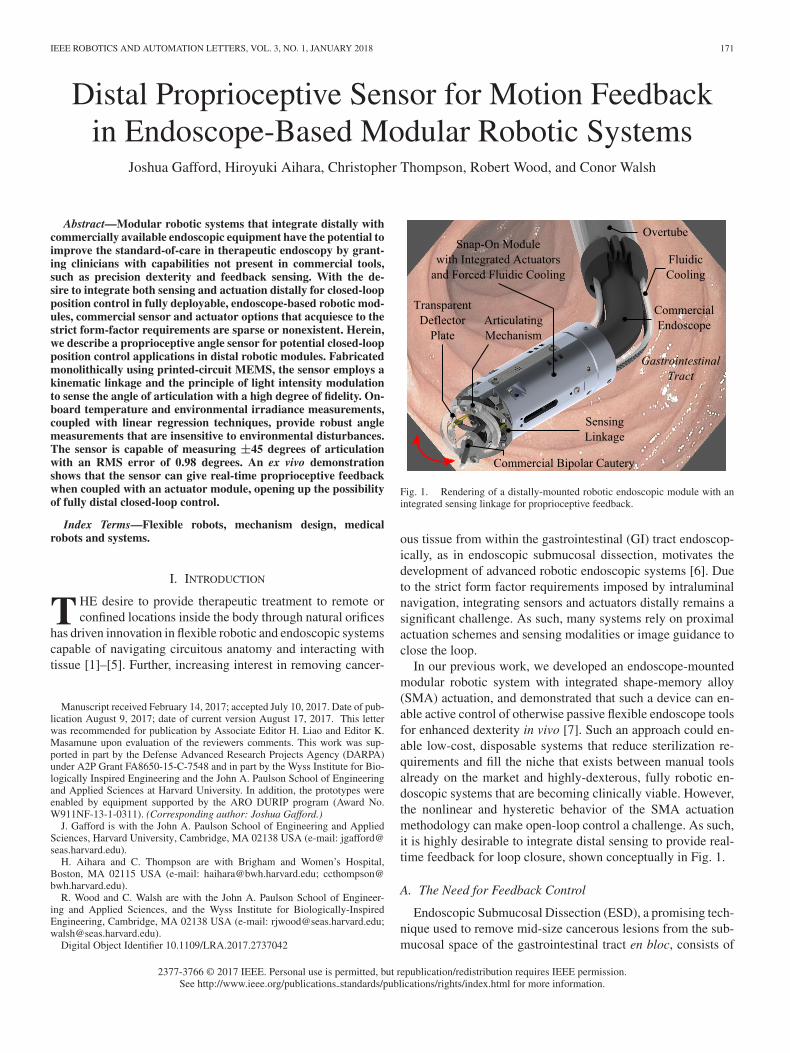
Fig. 1. Rendering of a distally-mounted robotic endoscopic module with anintegrated sensing linkage for proprioceptive feedback.
ous tissue from within the gastrointestinal (GI) tract endoscop-ically, as in endoscopic submucosal dissection, motivates thedevelopment of advanced robotic endoscopic systems [6]. Dueto the strict form factor requirements imposed by intraluminalnavigation, integrating sensors and actuators distally remains asignificant challenge. As such, many systems rely on proximalactuation schemes and sensing modalities or image guidance toclose the loop.
In our previous work, we developed an endoscope-mountedmodular robotic system with integrated shape-memory alloy(SMA) actuation, and demonstrated that such a device can en-able active control of otherwise passive flexible endoscope toolsfor enhanced dexterity in vivo [7]. Such an approach could en-able low-cost, disposable systems that reduce sterilization re-quirements and fill the niche that exists between manual toolsalready on the market and highly-dexterous, fully robotic en-doscopic systems that are becoming clinically viable. However,the nonlinear and hysteretic behavior of the SMA actuationmethodology can make open-loop control a challenge. As such,it is highly desirable to integrate distal sensing to provide real-time feedback for loop closure, shown conceptually in Fig. 1.
A. The Need for Feedback Control
Endoscopic Submucosal Dissection (ESD), a promising tech-nique used to remove mid-size cancerous lesions from the sub-mucosal space of the gastrointestinal tract en bloc, consists of
172 IEEE ROBOTICS AND AUTOMATION LETTERS, VOL. 3, NO. 1, JANUARY 2018
several subtasks that are cognitively burdensome to the endo-scopist due to the remote location of the lesions inside the GItract and the unintuitive mapping between the endoscope inputspace and resulting tip motion in task space. The subtask thatrequires the most dexterity involves making a series of lateralincisions underneath the lesion using side-cutting electrosurgi-cal tools to ‘lift off’ the lesion from the submucosal space. Thismaneuver manifests as a coupled motion consisting of a lateralsweeping motion to perform cutting and a slow retraction of thetool to provide tissue countertraction. Our desire is to potentiallyautomate low-level tasks such as the lateral sweeping motionwhile relegating master control over the endoscope’s gross mo-tion to the endoscopist in a collaborative control methodology,thereby reducing the cognitive loading on the practitioner.
From a technical perspective, the need for angle feedbacksensing for precision control in an antagonistic SMA configura-tion is apparent if we consider the complex thermomechanicalbehavior of the actuators [7]. For example, consider an open-loop control scenario where the clinician commands a positivearticulation angle, thereby passing a current to one of the actu-ators. When the command is removed, the SMA may continueto heat up, causing further motion which is undesirable for pre-cision control. In a closed-loop application, the sensor woulddetect this deviation from the setpoint, and subsequently flushthe previously active actuator while heating the bias actuatorto maintain the desired angle. In addition, as the flexible elec-trosurgical tool adds an uncertain elastic load in parallel to theantagonistic configuration scheme, a lack of position controlcould produce undesired motion when the control signal is re-moved and the tool stiffness overcomes the stiffness of the biasactuator, causing springback of the deflection plate which aposition controller would otherwise compensate for. As such,we would like to demonstrate the proposed sensor’s utility forreal-time angle feedback for potential closed-loop applications.
B. Contribution
Integrating robust, high-range proprioceptive sensing modali-ties distally remains a challenge that conventional approaches tomanufacturing are ill-suited for. The strict form-factor require-ments, specifically the requirement for an unobstructed borethrough which the commercial endoscope passes, precludes theuse of off-the-shelf sensor modalities. The motivation of thiswork is to develop a high-fidelity, high-range proprioceptive an-gular sensor to detect articulation in a distally-mounted roboticmodule for endoscopy. A secondary motivation is ‘mechanicaltransparency’, in that the sensor adds little to no additional stiff-ness to the system to maximize the net force generated by theactuators. As strain-based sensing modalities implicitly rely onthe elastic deformation of a continuum structure to sense deflec-tion which invariably adds stiffness to the overall system, thisapproach was quickly discarded [8]. Capacitance-based sensingmethodologies are not well suited for high-stroke applicationsand are highly susceptible to stray capacitances. A desire forlow-cost, deployability and modularity rules out electromag-netic and fiber-based sensing modalities (FBG, Fabry-Perot)which typically require expensive interrogation equipment and
Fig. 2. (a) Illustration of the coupling between the sensor linkage and theantagonistic SMA actuation modality (with transparent covers to show actuatordisplacement), (b) kinematic illustration of the sensor linkage given a positivearticulation angle θ.
introduce a necessary optical coupling between the distal endof the device and a proximal illumination and collection source[9], [10].
In our previous work, we have demonstrated the use of dis-crete emitter-detector (E/D) pairs and the principle of light-intensity modulation (LIM) to sense forces and displacements[11]. In this work, we explore monolithic fabrication techniquesto develop an angular proprioceptive sensor within the con-text of distal robotic modules for endoscopy capable of ac-tively articulating otherwise passive flexible endoscopic tools.By employing a kinematic linkage and the principle of LIM, ar-ticulation within the structure generated by on-board actuatorsdirectly translates to relative angular and linear displacementbetween emitter-detector pairs (as shown in Fig. 2(a)) to pro-duce a differential signal that can be used for position feedbackand closed-loop control. The methodologies presented in thiswork are generalizable to discrete shape sensing in continuumrobotics.
Section II presents a derivation of both kinematic and opto-electronic models used to predict sensor linkage performance.In Section III, we validate previously-derived analytical mod-els with a 10× experimental model to prove feasibility of theconcept. Section IV presents the fabrication of the to-scale sen-sor linkage. Section V discusses preliminary characterization
GAFFORD et al.: DISTAL PROPRIOCEPTIVE SENSOR FOR MOTION FEEDBACK IN ENDOSCOPE-BASED MODULAR ROBOTIC SYSTEMS 173
results, as well as an integrated demonstration where the sensorgives real-time proprioceptive feedback in an endoscope-basedrobotic module during ex vivo ESD. Conclusions and areas offuture work are discussed in Section VI.
II. KINEMATIC LINKAGE DESIGN AND MODELING
The linkage design employs two coupled 4-bar linkages andtheir resulting kinematics transform an input angle θ into arelative misalignment and displacement between two emitter-detector pairs situated on symmetric but opposite sides of thesystem, creating a differential signal to reject common-modenoise. The following section presents a complete derivation ofthe analytical model used to size the kinematic linkage andassess the performance of different emitter-detector pairs.
A. Kinematics Model
Consider the schematic shown in Fig. 2(b). An angular dis-placement θ is applied to input link O2 with respect to groundlink O1 by the actuators [7]. Kinematics dictate the transfor-mation between the input angle θ and relative output anglesψ between output links L, upon which optical emitter-detectorpairs are placed in opposing configurations.
Ultimately we would like a model that, for a given input angleθ, generates output voltages from the two phototransistors in thelinkage. As such, we must solve for the kinematics of the sys-tem, and use resulting relative linear and angular displacements(d1,2 and φ1,2 , respectively) in an optoelectronics model thatdescribes the incident irradiance attenuation factors due to dis-placement and misalignment, ultimately outputting the currentdrained by each phototransistor (and, subsequently, the voltagegiven a suitable signal conditioning model).
Henceforth, we define linkage k as the subset of all points thatbelong to their respective links (p ∈ {Lk1 → Lk2}). We definepoints as p{mk }
kj where k is the linkage to which the point belongs(1 or 2 according to Fig. 2(b)), j is a functional identifier (a, b,or f ), and {mk} is the coordinate frame of reference (which isimplicitly assigned to linkage k).
For rigid-body transformations, it is convenient to use ho-mogeneous transformation matrices (HTM) to express posi-tions and orientations in a local frame with respect to theinertial frame. For convenience, we define the following two-dimensional homogeneous transformation matrix (HTM):
H(α, δx, δy ) =
⎡⎢⎣
cos (α) − sin (α) δx
sin (α) cos (α) δy
0 0 1
⎤⎥⎦ (1)
where α is the angle of rotation about the z− axis, and δx andδy are translations in x and y, respectively. We can re-express
(2)where geometric parameters (e, ψ and l) are as defined in Fig. 2(vectors are padded so the algebra works out).
Although the forward kinematics are trivial to compute withHTMs given that we know linkage angles (i.e. given ψ, solvefor θ), we are actually interested in solving the inverse problem(i.e. given θ, solve for ψ). We use the observation that linkagesL1 and L2 are simply planar two-degree-of freedom revolute(RR) linkages with end-effector positions p{A 1 }
1f and p{A 2 }2f ex-
pressed in the inertial frames {Ak} assigned to each respectivelinkage. Given an input angle θ, we can use forward kinematicsto express these points in the global inertial frame {O}:
[p{O}•f 1
]T= H(θ, 0, h)[(−1)•e h 1]T (3)
Here we introduce • ∈ {1, 2} to denote the distinction be-tween L1 and L2 . To simplify subsequent algebra, we can ex-press these points in each linkage’s inertial frame:
[p{A •}•f 1
]T= H(0,−(−1)•e, 0)
[p{O}•f 1
]T(4)
Implementing the law of cosines, we can algebraically solvefor intermediate angles ψ•a and ψ•b as follows:
ψ•b = (−1)• cos−1
(||p{A •}
•f ||2 − 2l2
2l2
)(5)
ψ•a = tan−1
(p{A •}•f (2)
p{A •}•f (1)
)
− (−1)• cos−1
(||p{A •}
•f ||22l||p{A •}
•f ||
)(6)
where ||x|| is the Euclidean norm of x. Note that linkage 1 isthe redundant (‘elbow up’) solution, hence the addition of the(−1)• term which changes sign depending on the linkage beingconsidered. The angular misalignment φ• can be expressed as:
φ• = (−1)•π − ψ•b
2(7)
Finally, we can express the coordinates of emitter p{O}•a and
detector p{O}•b as:
p{O}•a = H(ψ•a , (−1)•e, 0) · [ c 0 1
]T(8)
p{O}•b = H(ψ•a , (−1)•e, 0) · H(ψ•b , l, 0) · [ l − c 0 1
]T(9)
The Euclidean distance separating emitter from detector isgiven by:
d• = ||p{O}•b − p{O}
•a || (10)
B. Optoelectronics Model
The kinematics of the system manifest as attenuation factorsin the optoelectronics model. The basis is a simple point-sourcemodel described more thoroughly in [12], where the irradiancefalls off with the square of the distance from the LED. The mis-alignment attenuation factor for the LED is adequately modeledby an inverse sigmoidal function with fit parameters α as given
174 IEEE ROBOTICS AND AUTOMATION LETTERS, VOL. 3, NO. 1, JANUARY 2018
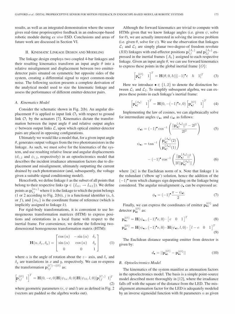
Fig. 3. Experiments with a 10× scale prototype, shown at extremes of travel.
by the following:
η•LED =α1
1 + exp (α2 − α3φ•)(11)
The misalignment attenuation factor for the PT is similarlydescribed with fit parameters β:
η•P T =β1
1 + exp (β2 − β3φ•)(12)
Finally, we can express the voltage generated by the photo-transistor by the following:
VP T = RP T η•P T η•LED
(γ1Φ4πd2•
+ γ2
)(13)
where RP T is the resistance value used to convert the collectorcurrent into a voltage, γ are curve fit parameters and Φ is theradiant intensity generated by the LED.
III. EXPERIMENTS WITH A SCALE MODEL
To validate the previously-derived analytical model, a 10×scaled-up version of the PCMEMS sensor kinematic structurewas built out of acrylic, as shown in Fig. 3. A potentiometermounted at the center of rotation of the input linkage providesa ground-truth measurement of the input angle θ. The outputlinks in the kinematic linkage have an array of mounting holes,allowing for arbitrary selection of the emitter-detector spatiallocation within the structure.
The goal of this scaled-up prototype is three-fold: (1) demon-strate feasibility of leveraging both displacement and misalign-ment within optoelectronic emitter-detector pairs to sense an-gular displacement, (2) validate previously-derived kinematicsand optoelectronics models, and (3) assess the performance oflinear regression models (with both linear and nonlinear featurespaces) on emitter-detector signals and the fidelity with whichthey approximate the true input angle.
A dynamic input was provided to the input link over thefull range of motion (roughly ±45 degrees). Meanwhile, po-tentiometer and phototransistor voltages were captured throughNI LabView at a rate of 1 kHz. Data were post-processed inMATLAB. A recursive least-squares (RLS) algorithm with aquadratic feature space was implemented to estimate the inputangle based on the E/D pair readings.
Example results are plotted in Fig. 4. The top plot showsthe actual angle θ compared to estimates θ̂mod and θ̂exp whichare estimated in real time using RLS. The second plot showsthe trace of the covariance matrix Pt used in RLS, which pro-vides a quantitative measure of estimator convergence. The third
Fig. 4. Comparison of analytical and experimental results with the 10× scalemodel: (from top) RLS estimated angle θ̂ (analytical and experimental) com-pared to the actual angle θ vs. time, trace of the RLS covariance matrix Ptvs. time (analytical and experimental) provided as an objective measure ofestimator convergence, phototransistor output voltage vs. time (analytical andexperimental), phototransistor output voltage vs. input angle θ (analytical andexperimental).
and fourth plots show the raw phototransistor output voltages(from both model and experiment) plotted against time and in-put angle, respectively. We observe that the experimental andanalytical results are nearly identical, speaking to the fidelity ofthe theoretical model. In addition, the use of a quadratic featurespace yields an exemplary estimate of the actual input angle andthe RMS error is less than 1 degree.
IV. TO-SCALE PROTOTYPE DESIGN AND FABRICATION
The 10× scale experimental model demonstrated concept fea-sibility in addition to validating the previously-derived analyti-cal model. To fabricate the sensor linkage at the scale appropriatefor distal implementation in endoscopy, we exploit alternativemanufacturing techniques as described in the following section.
A. PCMEMS Fabrication
The at-scale prototype was fabricated using printed-circuitMEMS (PCMEMS). The laminate consists of seven layers ofmaterial: two layers of 125 μm thick 304 stainless steel, onelayer of 50 μm thick Kapton polyimide, three layers of 25 μmFR0100 adhesive (duPont), and one layer of 25μm thick Kaptonwith an 18 μm thick Copper cladding. The typical steps ofthis manufacturing process are more thoroughly described in[13]. The layers are individually machined in a diode-pumped
GAFFORD et al.: DISTAL PROPRIOCEPTIVE SENSOR FOR MOTION FEEDBACK IN ENDOSCOPE-BASED MODULAR ROBOTIC SYSTEMS 175
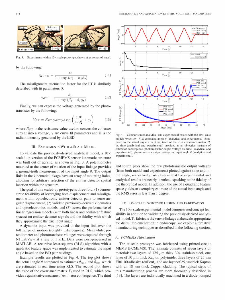
Fig. 5. Printed-circuit MEMS fabrication of the at-scale sensor linkage: (1) lamination of individually laser-machined material layers, (2) release cuts to freesensor linkage from alignment scaffold, (3) pick-and-placement of electronic components for reflow soldering, (4) tab-and-slot guided manual assembly.
Fig. 6. To-scale sensor linkages shown both pre- and post-assembly with aUS quarter for scale.
solid-state (DPSS) laser and laminated together using heat andpressure (1). Release cuts are made in the DPSS laser (2) andthe linkages are freed from their surrounding alignment scaffold.The top layer is a flexible circuit layer containing traces and landpatterns for sensors and passive components which are solderedusing reflow techniques (3). Finally, the linkage is manuallyassembled by out-of-plane folding and tab-and-slot assembly(4). This process is shown in Fig. 5. After component placement,the sensor is coated with a thin layer of silicone-based conformalcoating to electrically isolate components and traces from fluidicenvironments. Photographs of the sensor linkage both pre- andpost-assembly are shown in Fig. 6.
V. RESULTS AND DISCUSSION
A. Calibration
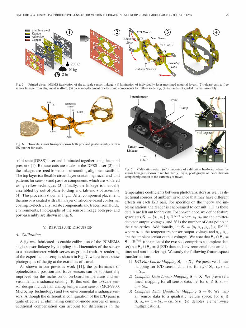
A jig was fabricated to enable calibration of the PCMEMSangle sensor linkage by coupling the kinematics of the sensorto a potentiometer which serves as ground truth. A renderingof the experimental setup is shown in Fig. 7, where insets showphotographs of the jig at the extremes of travel.
As shown in our previous work [11], the performance ofoptoelectronic position and force sensors can be substantiallyimproved via the inclusion of on-board temperature and en-vironmental irradiance sensing. To this end, the to-scale sen-sor design includes an analog temperature sensor (MCP9700,Microchip Technology) and two environmental irradiance sen-sors. Although the differential configuration of the E/D pairs isquite effective at eliminating common-mode sources of noise,additional compensation can account for differences in the
Fig. 7. Calibration setup: (left) rendering of calibration hardware where thesensor linkage is shown in red for clarity, (right) photographs of the calibrationsetup configuration at the extremes of travel.
temperature coefficients between phototransistors as well as di-rectional sources of ambient irradiance that may have differenteffects on each E/D pair. For specifics on the theory and im-plementation, the reader is encouraged to consult [11] as thesedetails are left out for brevity. For convenience, we define featurespace sets Ss = {s1 , s2} ∈ RN×2 where s1 , s2 are the emitter-detector output voltages, and N is the number of data points inthe time series. Additionally, let Se = {st , se1 , se2} ∈ RN×3 ,where st is the temperature sensor output voltage and se1 , se2are the ambient sensor output voltages. We note that Ss ∩ Se =S ∈ RN×5 (the union of the two sets comprises a complete dataset) but Ss ∪ Se = ∅ (E/D data and environmental data are dis-tinct and non-interfering). We study the following feature spacetransformations:
1) E/D Pair Linear Mapping Ss → Xs : We preserve a linearmapping for E/D sensor data, i.e. for so ∈ Ss , so �→ a+ bso .
2) Complete Data Linear Mapping S → X: We preserve alinear mapping for all sensor data, i.e. for so ∈ S, so �→a+ bso .
3) Complete Data Quadratic Mapping S → Φ: We mapall sensor data to a quadratic feature space: for so ∈S, so �→ a+ bso + cso � so (� denotes element-wisemultiplication).
176 IEEE ROBOTICS AND AUTOMATION LETTERS, VOL. 3, NO. 1, JANUARY 2018
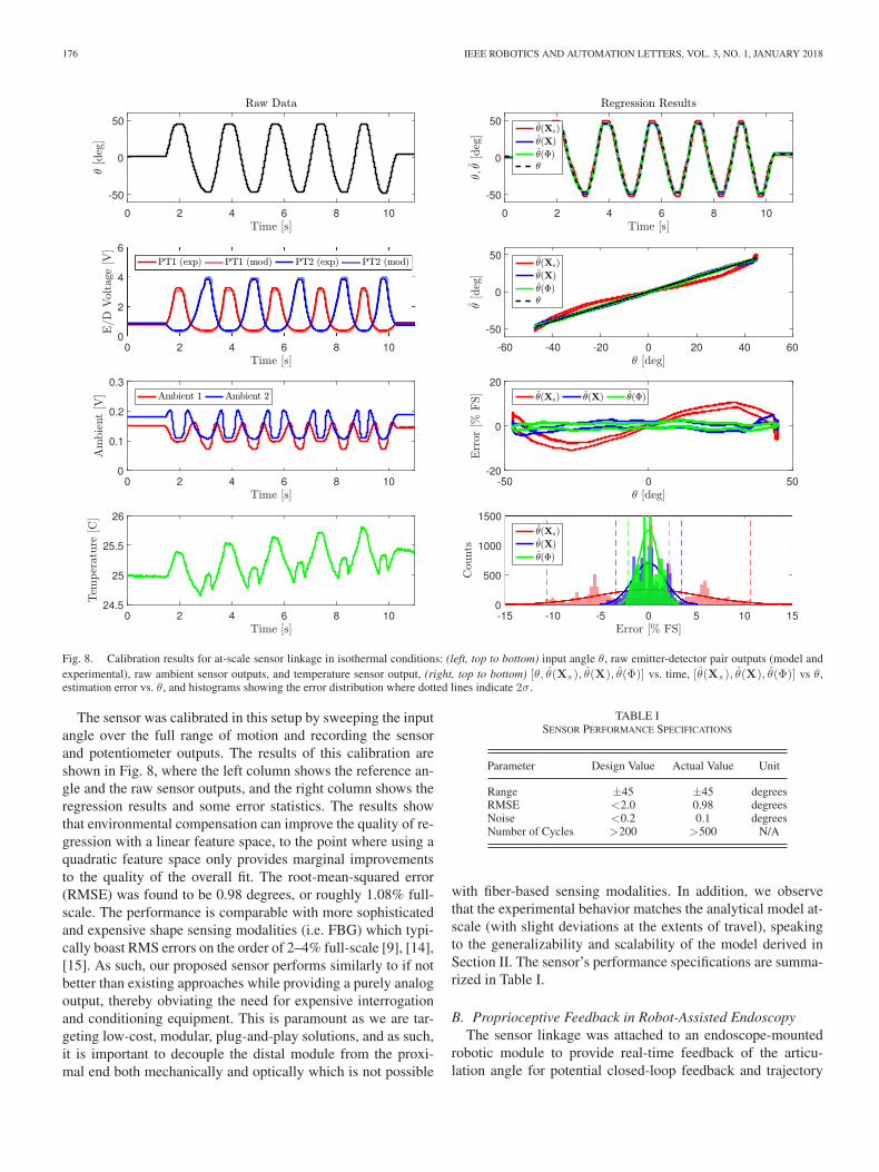
Fig. 8. Calibration results for at-scale sensor linkage in isothermal conditions: (left, top to bottom) input angle θ, raw emitter-detector pair outputs (model andexperimental), raw ambient sensor outputs, and temperature sensor output, (right, top to bottom) [θ, θ̂(Xs ), θ̂(X), θ̂(Φ)] vs. time, [θ̂(Xs ), θ̂(X), θ̂(Φ)] vs θ,estimation error vs. θ, and histograms showing the error distribution where dotted lines indicate 2σ.
The sensor was calibrated in this setup by sweeping the inputangle over the full range of motion and recording the sensorand potentiometer outputs. The results of this calibration areshown in Fig. 8, where the left column shows the reference an-gle and the raw sensor outputs, and the right column shows theregression results and some error statistics. The results showthat environmental compensation can improve the quality of re-gression with a linear feature space, to the point where using aquadratic feature space only provides marginal improvementsto the quality of the overall fit. The root-mean-squared error(RMSE) was found to be 0.98 degrees, or roughly 1.08% full-scale. The performance is comparable with more sophisticatedand expensive shape sensing modalities (i.e. FBG) which typi-cally boast RMS errors on the order of 2–4% full-scale [9], [14],[15]. As such, our proposed sensor performs similarly to if notbetter than existing approaches while providing a purely analogoutput, thereby obviating the need for expensive interrogationand conditioning equipment. This is paramount as we are tar-geting low-cost, modular, plug-and-play solutions, and as such,it is important to decouple the distal module from the proxi-mal end both mechanically and optically which is not possible
TABLE ISENSOR PERFORMANCE SPECIFICATIONS
Parameter Design Value Actual Value Unit
Range ±45 ±45 degreesRMSE <2.0 0.98 degreesNoise <0.2 0.1 degreesNumber of Cycles >200 >500 N/A
with fiber-based sensing modalities. In addition, we observethat the experimental behavior matches the analytical model at-scale (with slight deviations at the extents of travel), speakingto the generalizability and scalability of the model derived inSection II. The sensor’s performance specifications are summa-rized in Table I.
B. Proprioceptive Feedback in Robot-Assisted EndoscopyThe sensor linkage was attached to an endoscope-mounted
robotic module to provide real-time feedback of the articu-lation angle for potential closed-loop feedback and trajectory
GAFFORD et al.: DISTAL PROPRIOCEPTIVE SENSOR FOR MOTION FEEDBACK IN ENDOSCOPE-BASED MODULAR ROBOTIC SYSTEMS 177
Fig. 9. Block diagram of open-loop controller (with low-level PID current loop) used to demonstrate the proprioceptive sensor’s real-time feedback capabilitiesin a realistic application.
Fig. 10. Images of ex vivo test setup: (a) experimental setup, (b) close-up of a sensorized distal module in the vicinity of the porcine stomach, (c) module’spresence in the visual field of a standard endoscope.
execution purposes. An open-loop controller, shown schemati-cally in Fig. 9, was designed for robot-assisted endoscopy andfeatures a low-level PID current controller and an analog-to-PWM converter to sink current across the active SMA actuatorbased on a reference current profile. Low pass filters are imple-mented in software to filter out high frequency noise in boththe current sensor and on-board proprioceptive sensor mea-surements. In addition, a fluid logic controller actively coolsthe bias actuator to enhance actuation speed. An ergonomic,endoscope-mounted input device controls the direction of ar-ticulation. System data (desired vs. actual current profile, SMAelectrical resistance, fluid logic states, and on-board sensor data)is acquired at a rate of 1 kHz. The controller is embedded on aPC104 stack consisting of an Aurora SBC (Diamond Systems)running MATLAB xPC real-time kernel, and data is acquiredvia a MM-32DX-AT A/D board (Diamond Systems).
1) Ex-Vivo Test with Porcine Stomach: Collaborating withendoscopists at Brigham and Women’s hospital (Boston, MA),we used the sensorized module to perform a simulated ESD pro-cedure on an excised porcine stomach. The experimental setupis shown in Fig. 10(a). A photograph of the sensorized distalmodule is shown in Fig. 10(b), as well as a representative viewthrough the endoscope camera in Fig. 10(c). A simulated tumor
was marked on the porcine stomach, and saline fluid was injectedinto the submucosal space to lift the tumor off of the muscularis.The module was then used to deflect an Olympus DualKnifeelectrosurgical tool to create a circumferential incision aroundthe simulated tumor margin, and system data were recorded (asshown in Fig. 11, where we use the quadratic feature space overthe complete on-board sensor data set S → Φ to estimate theangle of articulation). We see a clear correlation between the ap-plied current and the angle of articulation, indicating that the sen-sor is capable of providing real-time proprioceptive angle feed-back. The on-board temperature sensor, in addition to providingdisturbance rejection for the proprioceptive sensor, is also usefulfor measuring the temperature of the system as a whole. As such,a higher-level controller can use this data to monitor the systemtemperature in the event that the SMAs heat up the entire modulenear the pain threshold, thereby triggering fluid flushing to coolthe system down back to an acceptable temperature. It is alsoimportant to note that electrosurgical pulses do not introduceany noise or contamination to the sensor readings. The ‘jumps’at 23 seconds and 28 seconds are likely due to fluid or particu-late occlusion in the emitter-detector light paths, illustrating theneed for physical encapsulation and isolation of emitter-detectorpairs.
178 IEEE ROBOTICS AND AUTOMATION LETTERS, VOL. 3, NO. 1, JANUARY 2018
Fig. 11. Integrated system controller and sensor data: (from top) current com-mands sent to each SMA, logic-level signals sent to fluid cooling solenoidvalves, emitter-detector pair output voltages, and estimated angle θ̂(Φ). Insetsshow photographs of the module during the incision process.
VI. CONCLUSIONS AND FUTURE WORK
Herein we present a monolithically-fabricated angular pro-prioceptive sensor based on a flexure-based kinematic linkageand the principle of light-intensity modulation for distal imple-mentation in endoscopic robotic systems. A complete analyticalmodel describing the coupled kinematics and optoelectronicswas derived and validated experimentally with a scaled-upmodel. Printed-circuit MEMS was employed to fabricate theat-scale prototype which was experimentally shown to be accu-rate over a range of ±45 degrees with an RMSE of 0.98 degrees.As a practical demonstration, the sensor linkage was attached toa distal robotic module and was used during a simulated ex vivoESD procedure. An open-loop controller was implemented tocontrol the deflection of a flexible electrosurgical tool, and thesensor demonstrated real-time angular feedback.
Future work will focus on the integration of encapsulatingstructures to protect the exposed emitter-detector pairs fromfluid and detritus that may be present during the procedure.While blood is uncommon during ESD as the procedure ismostly superficial, water, saline, and GI fluid could potentiallyblock the light paths between emitter-detector pairs, therebycompromising their operation. While sensor redundancy doespresent some robustness in the event that an emitter-detector pairgets blocked by fluid or debris, it is desirable to pursue mechan-ical encapsulating solutions to isolate the emitter-detector pairsfrom the environment. Leveraging recent work in combiningPCMEMS manufacturing with soft elastomeric materials [16],
the sensing linkage presented in this letter will be encapsulatedin a silicone bellows that will physically isolate the emitter-detector pairs without restricting motion of the articulatingmechanisms. We will work to further reduce the field-of-viewocclusion towards the aim of device transparency when notin use. We will also focus on the development of controllersthat will leverage on-board sensor feedback to control on-boardactuation, thereby demonstrating fully-distal loop closure inan endoscope-based robot for both teleoperation and low-leveltask automation in endoscopic procedures, specifically ESD. Inaddition, we are working closely with clinical collaborators todevelop an appropriate in vivo animal study in a porcine modelto demonstrate device robustness and utility in a clinically real-istic environment.
REFERENCES
[1] K. Taniguchi, A. Nishikawa, and M. Sekimoto, “Classification, designand evaluation of endoscope robots,” Robot Surg., vol. 1, pp. 1–24, Jan.2010.
[2] K.-y. Ho et al., “Endoscopic submucosal dissection of gastric lesions byusing a Master and Slave Transluminal Endoscopic Robot (MASTER).”Gastrointestinal Endoscopy, vol. 72, no. 3, pp. 593–599, 2010.
[3] G. P. Mylonas, V. Vitiello, T. P. Cundy, A. Darzi, and G.-z. Yang,“CYCLOPS : A versatile robotic tool for bimanual single-access andnatural-orifice endoscopic surgery,” in Proc. IEEE Int. Conf. Robot. Au-tom., 2014, pp. 2436–2442.
[4] J. Ruiter, E. Rozeboom, M. Van Der Voort, M. Bonnema, and I. Broeders,“Design and evaluation of robotic steering of a flexible endoscope,” inProc. IEEE RAS EMBS Int. Conf. Biomed. Robot. Biomechatronics, 2012,pp. 761–767.
[5] M. F. Traeger, D. B. Roppenecker, M. R. Leininger, F. Schnoes, and T. C.Lueth, “Design of a spine-inspired kinematic for the guidance of flexibleinstruments in minimally invasive surgery,” in Proc. 2014 IEEE/RSJ Int.Conf. Intell. Robots Syst., 2014, pp. 1322–1327.
[6] B. P. M. Yeung and P. W. Y. Chiu, “Application of robotics in gastroin-testinal endoscopy: A review,” World J. Gastroenterology, vol. 22, no. 5,pp. 1811–1825, 2016.
[7] J. Gafford, R. Wood, and C. Walsh, “A high-force, high-stroke distalrobotic add-on for endoscopy,” in Proc. IEEE Int. Conf. Robot. Autom.,2017, pp. 1117–1124.
[8] Y. Chen, J. M. Oliveira, and I. W. Hunter, “Two-axis bend sensor design,kinematics and control for a continuum robotic endoscope,” in Proc. IEEEInt. Conf. Robot. Autom., 2013, pp. 704–710.
[9] S. C. Ryu and P. E. Dupont, “FBG-based shape sensing tubes for contin-uum robots,” in Proc. IEEE Int. Conf. Robot. Autom., 2014, pp. 3531–3537.
[10] C. Shi et al., “Shape sensing techniques for continuum robots in minimallyinvasive surgery: A survey,” IEEE Trans. Biomed. Eng., vol. 64, no. 8,pp. 1665–1678, Aug. 2017.
[11] J. Gafford, F. Doshi-Velez, R. Wood, and C. Walsh, “Machine learningapproaches to environmental disturbance rejection in multi-axis optoelec-tronic force sensors,” Sensors Actuators A, Phys., vol. 248, pp. 78–87,2016.
[12] J. B. Gafford, R. J. Wood, and C. J. Walsh, “Self-assembling, low-cost,and modular mm-scale force sensor,” IEEE Sensors J., vol. 16, no. 1,pp. 69–76, Jan. 2016.
[13] J. Gafford et al., “Towards medical devices with integrated mechanisms,sensors and actuators via printed-circuit MEMS,” J. Med. Devices, vol. 11,no. 1, 2017, Art. no. 011007.
[14] H. Liu, A. Farvardin, S. A. Pedram, I. Iordachita, R. H. Taylor, andM. Armand, “Large deflection shape sensing of a continuum manipulatorfor minimally-invasive surgery,” in Proc. IEEE Int. Conf. Robot. Autom.,May 2015, pp. 201–206.
[15] S. Sefati, F. Alambeigi, I. Iordachita, M. Armand, R. J. Murphy, andM. Armand, “Fbg-based large deflection shape sensing of a continuummanipulator: Manufacturing optimization,” in Proc. IEEE SENSORS, Oct.2016, pp. 1–3.
[16] S. Russo, T. Ranzani, J. Gafford, C. J. Walsh, and R. J. Wood, “Softpop-up mechanisms for micro surgical tools: Design and characterizationof compliant millimeter-scale articulated structures,” in Proc. IEEE Int.Conf. Robot. Autom., May 2016, pp. 750–757.