No part of this publication may be reproduced in any form, in an electronic retrieval system or otherwise, without the prior written permission of the publisher.
IEEE Std C62.11-1999
(Revision ofIEEE Std C62.11-1993)
IEEE Standard for Metal-OxideSurge Arresters for AC Power Circuits (> 1 kV)
Sponsor
Surge Protective Devices Committeeof theIEEE Power Engineering Society
Approved 22 March 1999
IEEE-SA Standards Board
Abstract:
Metal-oxide surge arresters designed to repeatedly limit the voltage surges on 48–62 Hzpower circuits (>1 kV) are covered in this standard. These devices operate by discharging surgecurrent. Devices for separate mounting and those supplied integrally with other equipment are alsodiscussed.
Keywords:
classifying current, discharge current, discharge voltage, duty-cycle voltage rating,maximum continuous operating voltage (MCOV), maximum design cantilever load-static(MDCL-static), metal-oxide surge arrester (MOSA), operating duty cycle, rating, reference current(Iref), reference voltage (Vref), sparkover, surge arrester, ultimate mechanical strength-static(UMS-static), valve
IEEE Standards
documents are developed within the IEEE Societies and the Standards Coordinating Com-mittees of the IEEE Standards Association (IEEE-SA) Standards Board. Members of the committees servevoluntarily and without compensation. They are not necessarily members of the Institute. The standardsdeveloped within IEEE represent a consensus of the broad expertise on the subject within the Institute aswell as those activities outside of IEEE that have expressed an interest in participating in the development ofthe standard.
Use of an IEEE Standard is wholly voluntary. The existence of an IEEE Standard does not imply that thereare no other ways to produce, test, measure, purchase, market, or provide other goods and services related tothe scope of the IEEE Standard. Furthermore, the viewpoint expressed at the time a standard is approved andissued is subject to change brought about through developments in the state of the art and commentsreceived from users of the standard. Every IEEE Standard is subjected to review at least every five years forrevision or reaffirmation. When a document is more than five years old and has not been reaffirmed, it is rea-sonable to conclude that its contents, although still of some value, do not wholly reflect the present state ofthe art. Users are cautioned to check to determine that they have the latest edition of any IEEE Standard.
Comments for revision of IEEE Standards are welcome from any interested party, regardless of membershipaffiliation with IEEE. Suggestions for changes in documents should be in the form of a proposed change oftext, together with appropriate supporting comments.
Interpretations: Occasionally questions may arise regarding the meaning of portions of standards as theyrelate to specific applications. When the need for interpretations is brought to the attention of IEEE, theInstitute will initiate action to prepare appropriate responses. Since IEEE Standards represent a consensus ofall concerned interests, it is important to ensure that any interpretation has also received the concurrence of abalance of interests. For this reason, IEEE and the members of its societies and Standards CoordinatingCommittees are not able to provide an instant response to interpretation requests except in those cases wherethe matter has previously received formal consideration.
Comments on standards and requests for interpretations should be addressed to:
Authorization to photocopy portions of any individual standard for internal or personal use is granted by theInstitute of Electrical and Electronics Engineers, Inc., provided that the appropriate fee is paid to CopyrightClearance Center. To arrange for payment of licensing fee, please contact Copyright Clearance Center, Cus-tomer Service, 222 Rosewood Drive, Danvers, MA 01923 USA; (978) 750-8400. Permission to photocopyportions of any individual standard for educational classroom use can also be obtained through the Copy-right Clearance Center.
Note: Attention is called to the possibility that implementation of this standard mayrequire use of subject matter covered by patent rights. By publication of this standard,no position is taken with respect to the existence or validity of any patent rights inconnection therewith. The IEEE shall not be responsible for identifying patents forwhich a license may be required by an IEEE standard or for conducting inquiries intothe legal validity or scope of those patents that are brought to its attention.
[This introduction is not part of IEEE Std C62.11-1999, IEEE Standard for Metal-Oxide Surge Arresters for AC PowerCircuits (> 1 kV).]
This standard presents minimum criteria for the testing of metal-oxide surge arresters that are applied to acpower systems above 1 kV (1000 V).
Metal-oxide surge arresters described in this standard are the most predominant arrester technology appliedon ac power systems above 1 kV. Other valve-type arresters are covered in IEEE Std C62.1-1989. For pro-tection of low-voltage circuits, including vulnerable or susceptible electronics, the latest standards publishedin the C62 series should be consulted.
This standard is written for metal-oxide surge arresters both with and without spark gaps.
The following additions are included in this revision:
a) Expanded definitions for basic lightning impulse insulation level (BIL);
b) New definitions for maximum design cantilever load-static (MDCL-static) and ultimate mechanicalstrength-static (UMS-static);
c) Short-circuit design tests for polymer-housed distribution arresters;
d) MDCL-static tests for polymer-housed arresters;
e) UMS-static tests for porcelain-housed arresters;
f) Expanded routine test requirements.
This standard was developed by three working groups within the Surge Protective Devices Committee.
Working Group No. 3.3.8 had the following membership:
S. Brewer and D. W. Lenk,
Chairs
Working Group No. 3.3.10 had the following membership:
K. Nolan and A. Maguire,
Chairs
J. BennettT. Bialek J. Case M. G. Comber T. Compton M. DeNigris C. C. Erven P. Freeman T. Hartman
B. Johnnerfelt J. Kester M. V. Lat G. E. Lee A. Lim P. Lindemuld J. Mackevich A. Maguire N. McQuin
J. C. OsterhoutB. ParsonsT. RozekB. SteinbrecherE. TarasiewiczR. ThallamA. VitolsJ. WilsonJ. J. Woodworth
J. Bennett T. Bialek S. Brewer J. Burke J. Case M. G. Comber T. Compton J. P. DuPont M. DeNigrisC.C. Erven
R. E. Foelker T. Hartman S. Hensley B. Johnnerfelt J. Kester D. Kundu M. V. Lat D. W. Lenk J. Levine A. Lim
J. MackevichN. McQuin J. C. Osterhout T. Rozek B. Steinbrecher E. Tarasiewicz R. Thallam A. Vitols B. Wolinski J. J. Woodworth
Working Group No. 3.3.11 had the following membership:
J. Kester and M. V. Lat,
Chairs
The following members of the balloting committee voted on this standard:
When the IEEE-SA Standards Board approved this standard on 22 March 1999, it had the followingmembership:
Richard J. Holleman,
Chair
Donald N. Heirman,
Vice Chair
Judith Gorman,
Secretary
*Member Emeritus
Janet Rutigliano
IEEE Standards Project Editor
J. Bennett T. Bialek R. Bommakaul S. Brewer J. Case M. G. Comber T. Compton M. DeNigris J. P. DuPont C. C. Erven P. FreemanG. Gaibrois
S. Hensley D. Jackson B. Johnnerfelt G. E. LeeD. W. LenkJ. Levine A. Lim J. MackevichA. Maguire N. McQuin R. Moore
J. C. Osterhout J. Posey T. Rozek B. Steinbrecher K. B. Stump E. Tarasiewicz E. R. Taylor R. Thallam A. Vitols J. Williams J. Wilson J. J. Woodworth
Phil P. BarkerJohn S. BonnesenH. Steve BrewerJames J. BurkeJames CaseMike G. ComberRandall L. DotsonCliff, C. ErvenFrancis J. FiederleinHarald FienLaurence H. FishErnie GalloGeorge S. HaralampuSteven P. HensleyAndrew Robert HilemanDavid W. HutchinsHieu HuynhDavid W. Jackson
Bengt JohnnerfeltJeff J. KesterEd KnappJoseph L. KoepfingerAlan E. KollarDebu KunduBenny H. LeeGerald E. LeeDennis W. LenkPaul LindemulderW. Al MaguireFrancois D. MartzloffNigel P. McQuinDaleep C. MohlaYasin I. MusaKen NolanRichard OdenbergJoseph C. OsterhoutCarlos Peixoto
John B. PoseyJesus Martinez RodriquezTim E. RoysterThomas J. RozekHans SteinhoffKeith B. StumpLewis Douglas SweeneyAndy SweetanaEva J. TarasiewiczEdgar TaylorArnold VitolsMatthew S. WakehamArthur C. WestromSteve G. WhisenantJames Jr. WilsonJonathan J. WoodworthDonald M. WordenJanusz Zawadzki
Satish K. AggarwalClyde R. CampJames T. CarloGary R. EngmannHarold E. EpsteinJay Forster*Thomas F. GarrityRuben D. Garzon
James H. GurneyJim D. IsaakLowell G. JohnsonRobert KennellyE. G. “Al” KienerJoseph L. Koepfinger*Stephen R. LambertJim LogothetisDonald C. Loughry
L. Bruce McClungLouis-François PauRonald C. PetersenGerald H. PetersonJohn B. PoseyGary S. RobinsonHans E. WeinrichDonald W. Zipse
4. Service conditions................................................................................................................................ 8
4.1 Usual service conditions .............................................................................................................. 84.2 Unusual service conditions .......................................................................................................... 8
5. Standard voltage ratings: duty-cycle voltage and maximum continuousoperating voltage (MCOV) .................................................................................................................. 9
6. Performance characteristics and tests ................................................................................................ 10
7. Test procedure.................................................................................................................................... 11
7.1 Complete arrester test specimens............................................................................................... 117.2 Prorated arrester test section ...................................................................................................... 127.3 Test measurements..................................................................................................................... 157.4 Impulse test-wave tolerances ..................................................................................................... 157.5 Power-frequency test voltages ................................................................................................... 16
for distribution class arresters .................................................................................................... 248.7 Contamination test ..................................................................................................................... 278.8 Distribution class surge arrester seal integrity test .................................................................... 288.9 Internal-ionization voltage (IIV) and RIV tests ......................................................................... 298.10 Discharge-current withstand tests .............................................................................................. 308.11 Duty-cycle tests.......................................................................................................................... 368.12 TOV tests ................................................................................................................................... 378.13 Pressure-relief tests for station and intermediate class arresters................................................ 398.14 Short-circuit test for porcelain-housed distribution surge arresters ........................................... 428.15 Short-circuit test for polymer-housed distribution class arresters ............................................. 448.16 Failure mode test for liquid-immersed arresters ........................................................................ 478.17 Deadfront arrester failure mode ................................................................................................. 488.18 Distribution arrester disconnector tests...................................................................................... 498.19 Maximum design cantilever load-static (MDCL-static) test ..................................................... 518.20 Ultimate mechanical strength-static (UMS-static) tests for porcelain-housed arresters............ 53
9. Conformance tests of valve arresters ................................................................................................. 53
10.1 Identification data ...................................................................................................................... 5410.2 Standard mountings ................................................................................................................... 5410.3 Iron and steel parts ..................................................................................................................... 5510.4 Terminal connections................................................................................................................. 5510.5 Housing leakage distance........................................................................................................... 55
13.1 Current-sharing test.................................................................................................................... 5813.2 Discharge-voltage test................................................................................................................ 5913.3 Ionization voltage test ................................................................................................................ 5913.4 Seal test ...................................................................................................................................... 5913.5 Power-frequency test ................................................................................................................. 5913.6 Power-frequency sparkover ....................................................................................................... 60
Annex A (informative) Basis for accelerated aging procedure ..................................................................... 61
Annex B (informative) Surge arrester classification prescribed test requirements ....................................... 63
IEEE Standard for Metal-OxideSurge Arresters for AC PowerCircuits (> 1 kV)
1. Scope
This standard applies to metal-oxide surge arresters (MOSA) designed to repeatedly limit the voltage surgeson 48–62 Hz power circuits (> 1 kV) by passing surge discharge current and automatically limiting the flowof system power current. This standard applies to devices for separate mounting and to those suppliedintegrally with other equipment.
2. References
This standard shall be used in conjunction with the following publications. If the following publications aresuperseded by an approved revision, the revision shall apply.
ANSI C37.42-1996, American National Standard for Switchgear—Distribution Cutouts and Fuse Links—Specifications.
1
ANSI C84.1-1995, American National Standard for Electric Power Systems and Equipment—VoltageRatings (60 Hz).
ASTM A153/A13M-98, Standard Specification for Zinc Coating (Hot-Dip) on Iron and Steel Hardware.
2
ASTM D750-95, Standard Test Method for Rubber Deterioration in Carbon-Arc Weathering Apparatus.
ASTM D1499-92a, Standard Practice for Operating Light- and Water-Exposure Apparatus (Carbon-ArcType) for Exposure of Plastics.
1
ANSI publications are available from the Sales Department, American National Standards Institute, 11 West 42nd Street, 13th Floor,New York, NY 10036, USA (http://www.ansi.org/). This particular standard is also available from the Institute of Electrical and Elec-tronics Engineers, 445 Hoes Lane, P.O. Box 1331, Piscataway, NJ 08855-1331, USA (http://www.standards.ieee.org/).
2
ASTM publications are available from the American Society for Testing and Materials, 100 Barr Harbor Drive, West Conshohocken,PA 19428-2959, USA (http://www.astm.org/).
IEEEStd C62.11-1999 IEEE STANDARD FOR METAL-OXIDE SURGE ARRESTERS
ASTM D2556-93a, Standard Test Method for Apparent Viscosity of Adhesives Having Shear-Rate-Depen-dent Flow Properties.
ASTM D3487-88 (1993), Standard Specification for Mineral Insulating Oil Used in Electrical Apparatus.
ASTM G23-96, Standard Practice for Operating Light-Exposure Apparatus (Carbon-Arc Type) With andWithout Water for Exposure of Nonmetallic Materials.
ASTM G26-96, Standard Practice for Operating Light-Exposure Apparatus (Xenon-Arc Type) With andWithout Water for Exposure of Nonmetallic Materials.
ASTM G53-96, Standard Practice for Operating Light- and Water-Exposure Apparatus (Fluorescent UV-Condensation Type) for Exposure of Nonmetallic Materials.
IEEE Std 4-1995, IEEE Standard Techniques for High-Voltage Testing.
3
IEEE Std 386-1995, IEEE Standard for Separable Insulated Connector Systems for Power Distribution Sys-tems Above 600 V.
IEEE Std 1313.1-1996, IEEE Standard for Insulation Coordination—Definitions, Principles, and Rules(Revision and redesignation of IEEE Std 1313-1993).
IEEE Std C37.09-1979 (Reaff 1988), IEEE Standard Test Procedure for AC High-Voltage Circuit BreakersRated on a Symmetrical Current Basis (ANSI/DoD).
IEEE Std C62.22-1997, IEEE Guide for the Application of Metal-Oxide Surge Arresters for Alternating-Current Systems.
NEMA LA 1-1992, Surge Arresters.
4
NEMA 107-1987 (R1993), Methods of Measurement of Radio-Influence Voltage (RIV) of High VoltageApparatus.
3. Definitions
The following definitions apply to metal-oxide surge arresters. They do not necessarily cover otherapplications.
3.1 arrester:
See
:
surge arrester
.
3.2 arrester, deadfront type:
An arrester assembled in a shielded housing providing system insulation andconductive ground shield, intended to be installed in an enclosure for the protection of underground and pad-mounted distribution equipment and circuits.
3.3 arrester disconnector:
A means for disconnecting an arrester in anticipation of, or after, a failure inorder to prevent a permanent fault on the circuit and to give indication of a failed arrester.
Note
: Clearing ofthe fault current through the arrester during disconnection is generally done by the nearest source side over-current-protective device.
3
IEEE publications are available from the Institute of Electrical and Electronics Engineers, 445 Hoes Lane, P.O. Box 1331, Piscataway,NJ 08855-1331, USA (http://www.standards.ieee.org/).
4
NEMA publications are available from Global Engineering Documents, 15 Inverness Way East, Englewood, Colorado 80112, USA(http://www.global.ihs.com/).
IEEEFOR ALTERNATING-CURRENT POWER CIRCUITS Std C62.11-1999
An arrester normally used to protect overhead distribution sys-tems exposed to severe lightning currents.
3.5 arrester, distribution, light duty class:
An arrester normally installed on and used to protect under-ground distribution systems where the major portion of the lightning stroke current is discharged by anarrester located at the overhead line/cable junction.
3.6 arrester, distribution, normal duty class:
An arrester normally used to protect overhead distributionsystems exposed to normal lightning currents.
3.7 arrester, liquid-immersed type:
An arrester designed for use immersed in an insulating liquid.
3.8 arrester, riser pole type:
An arrester for pole mounting normally used to protect underground distribu-tion cable and equipment.
The electrical strength of insulation expressed interms of the crest value of a standard lightning impulse under standard atmospheric conditions. BIL may beexpressed as either statistical or conventional (see IEEE Std 1313.1-1996).
(B)
A specific insulation levelexpressed as the crest value of a standard lightning impulse (see ANSI C92.1-1982 and IEEE Std C62.22-1991).
—
BIL (conventional):
Applicable specifically to non-self-restoring insulations. The crest value of astandard lightning impulse for which the insulation does not exhibit disruptive discharge when sub-jected to a specific number of applications of this impulse under specified conditions (see IEEE StdC62.2-1987).
—
BIL (statistical):
Applicable specifically to self-restoring insulations. The crest value of a standardlightning impulse for which the insulation exhibits a 90% probability of withstand (or a 10% proba-bility of failure) under specified conditions (see IEEE Std C62.2-1987).
The electrical strength of insulation expressed interms of the crest value of a standard switching impulse. BSL may be expressed as either statistical or con-ventional (see ANSI C92.2-1982 and IEEE Std C62.2-1987).
(B)
A specific insulation level expressed as thecrest value of a standard switching impulse (see ANSI C92.1-1982 and IEEE Std C62.22-1991).
—
BSL (conventional):
Applicable specifically to non-self-restoring insulations. The crest value of astandard switching impulse for which the insulation does not exhibit disruptive discharge when sub-jected to a specific number of impulses under specified conditions (see IEEE Std C62.2-1987).
—
BSL (statistical):
Applicable specifically to self-restoring insulations. The crest value of a standardswitching impulse for which the insulation exhibits a 90% probability of withstand (or a 10% proba-bility of failure) under specified conditions (see IEEE Std C62.2-1987).
3.12 certification tests:
Tests run on a regular, periodic basis to verify that selected key performance charac-teristics of a product, or representative samples thereof, have remained within performance specifications.
3.13 classification of arresters:
Arrester classification is determined by the prescribed test requirements ofthis standard. These classifications are: station, intermediate, distribution heavy duty, distribution normalduty, distribution light duty.
3.14 classifying current:
The designated current used to perform the classification tests.
Note
: See Annex Bfor a summary of test parameters by classification.
3.15 conformance tests:
Tests made, when required, to demonstrate selected performance characteristics ofa product or representative samples thereof.
Note
: See Table 4, Table 5, and Table 6 in Clause 8.
IEEEStd C62.11-1999 IEEE STANDARD FOR METAL-OXIDE SURGE ARRESTERS
Rupture of the weathershed material to depths greater than 0.1 mm.
3.17 crest (peak) value (of a wave, surge, or impulse):
The maximum value that a wave, surge, or impulseattains.
3.18 current, normal lightning:
Lightning currents of 65 kA or less.
3.19 current, severe lightning:
Lightning currents greater than 65 kA, but not greater than 100 kA.
3.20 deflector:
A means for directing the flow of gas discharge from the vent of the arrester.
3.21 design tests:
Tests made on each design to establish the performance characteristics and to demonstratecompliance with the appropriate standards of the industry. Once made they need not be repeated, unless thedesign is changed so as to modify performance.
3.22 discharge counter:
A means for recording the number of arrester discharge operations.
3.23 discharge current:
The surge current that flows through an arrester.
3.24 discharge indicator:
A means for indicating that the arrester has discharged.
3.25 discharge voltage:
The voltage that appears across the terminals of an arrester during passage of dis-charge current.
3.26 discharge voltage-current characteristic:
The variation of the crest values of discharge voltage withrespect to discharge current.
Note
: This characteristic is normally shown as a graph based on three or morecurrent-surge measurements of the same wave shape, but of different crest values.
3.27 discharge withstand current:
The specified magnitude and wave shape of a discharge current that canbe applied to an arrester a specified number of times without causing damage to it.
3.28 disruptive discharge:
The sudden and large increase in current through an insulating medium, due tothe complete failure of the medium under electrostatic stress.
3.29 duty-cycle voltage rating:
The designated maximum permissible voltage between its terminals atwhich an arrester is designed to perform its duty cycle.
3.30 fault current:
The current from the connected power system that flows in a short circuit.
3.31 flashover:
A disruptive discharge around or over the surface of a solid or liquid insulator.
3.32 front-of-wave impulse sparkover voltage:
The impulse sparkover voltage with a wavefront that risesat a uniform rate and causes sparkover on the wavefront.
3.33 gapless:
Not possessing gaps, series or parallel, as in “gapless arrester.”
3.34 grading or control ring:
A metal part, usually circular or oval in shape, mounted to modify electrostat-ically the voltage gradient or distribution.
3.35 ground terminal:
The conducting part provided for connecting the arrester to ground.
3.36 impulse:
A surge of unidirectional polarity.
IEEEFOR ALTERNATING-CURRENT POWER CIRCUITS Std C62.11-1999
For a defined wave shape, the higher of the maximum sparkover value or thecorresponding discharge-voltage value.
3.38 impulse protective volt-time characteristic:
The discharge-voltage-time response of the device toimpulses of a designated wave shape and polarity, but of varying magnitudes.
3.39 impulse sparkover voltage:
The highest value of voltage attained by an impulse of a designated waveshape and polarity applied across the terminals of an arrester that will cause gap sparkover prior to the flowof discharge current.
3.40 impulse sparkover volt-time characteristic:
The gap sparkover response of the device to impulses ofa designated wave shape and polarity, but of varying magnitudes.
Note
: For an arrester, this characteristic isshown by a graph of crest voltage values plotted against time-to-sparkover.
3.41 impulse withstand voltage:
The crest value of an impulse that, under specified conditions, can beapplied without causing a disruptive discharge.
3.42 indoor arrester:
An arrester that, because of its construction, must be protected from the weather.
3.43 ionization current:
The electric current resulting from the movement of electric charges in an ionizedmedium, under the influence of an applied electric field.
3.44 ionization voltage:
A high-frequency voltage appearing at the terminals of an arrester, generated by allsources, but particularly by ionization current within the arrester, when a power-frequency voltage is appliedacross the terminals.
3.45 lightning:
An electric discharge that occurs in the atmosphere between clouds or between clouds andground.
3.46 lightning surge:
A transient electric disturbance in an electric circuit caused by lightning.
3.47 line terminal:
The conducting part of the arrestor provided for connecting the arrester to the circuitconductor.
Note
: When a line terminal is not supplied as an integral part of the arrester, and the series gap isobtained by providing a specified air clearance between the line end of the arrester and a conductor, or arcingelectrode, etc., the words “line terminal” used in the definition refer to the conducting part that is at linepotential and that is used as the line electrode of the series gap.
3.48 maximum continuous operating voltage (MCOV):
The maximum designated root-mean-square(rms) value of power-frequency voltage that may be applied continuously between the terminals of thearrester.
3.49 maximum design cantilever load-static (MDCL-static):
The maximum cantilever load the surgearrester is designed to continuously carry.
3.50 maximum system voltage:
The highest voltage at which a system is operated.
Note
: This is generallyconsidered to be the maximum system voltage as prescribed in ANSI C84.1-1995.
3.51 metal-oxide surge arrester (MOSA):
A surge arrester utilizing valve elements fabricated from non-linear resistance metal-oxide materials.
3.52 nominal rate of rise (of an impulse):
For a wavefront, the slope of the line that determines the virtualzero. It is usually expressed in volts or amperes per microsecond.
IEEEStd C62.11-1999 IEEE STANDARD FOR METAL-OXIDE SURGE ARRESTERS
A nominal value assigned to designate a system of a given voltage class.
Note
: See ANSI C84.1-1995.
3.54 operating duty cycle:
One or more unit operations, as specified.
3.55 oscillatory surge:
A surge that includes both positive and negative polarity values.
3.56 outdoor arrester:
An arrester that is designed for outdoor use.
3.57 power-frequency sparkover voltage:
The rms value of the lowest power-frequency sinusoidal voltagethat will cause sparkover when applied across the terminals of an arrester.
3.58 power-frequency withstand voltage:
A specified rms test voltage at power frequency that will notcause a disruptive discharge.
3.59 production tests:
See
:
routine tests
.
3.60 prorated section:
A complete, suitably housed part of an arrester, comprising all necessary compo-nents, including gaseous medium, in such a proportion as to accurately represent, for a particular test, thecharacteristics of a complete arrester.
3.61 puncture:
(A)
A disruptive discharge through the body of a solid dielectric.
(B)
A disruptive dischargethrough solid insulation.
(C)
Term used to denote when a disruptive discharge occurs through a solid dielec-tric and produces permanent loss of dielectric strength; in a liquid or gaseous dielectric, the loss may be onlytemporary.
3.62 radio-influence voltage (RIV):
A high-frequency voltage, generated by all sources of ionization cur-rent, that appears at the terminals of electric-power apparatus or on power circuits.
3.63 rating:
The designation of an operating limit for a device.
3.64 reference current (Iref):
The peak value of the resistive component of a power-frequency current highenough to make the effects of stray capacitance of the arrester negligible. This current level shall be specifiedby the manufacturer.
Note
: Depending on the arrester design, the Iref will typically be in the range of0.05–1.0 mA per sq cm of disk area.
3.65 reference voltage (Vref):
The lowest peak value independent of polarity of power-frequency voltage,divided by the square root of 2, required to produce a resistive component of current equal to the referencecurrent of the arrester or arrester element. The reference voltage of a multiunit arrester is the sum of the ref-erence voltages of the series units. The voltage level shall be specified by the manufacturer.
3.66 routine tests:
Tests made by the manufacturer on every device or representative samples, or on parts ormaterials, as required, to verify that the product meets the design specifications.
3.67 series gap:
An intentional gap(s) between spaced electrodes in series with the valve elements acrosswhich all or part of the impressed arrester terminal voltage appears.
3.68 shunt gap:
An intentional gap(s) between spaced electrodes that is electrically in parallel with one ormore valve elements.
3.69 sparkover:
A disruptive discharge between electrodes of a measuring gap, voltage-control gap, or gap-type protective device.
IEEEFOR ALTERNATING-CURRENT POWER CIRCUITS Std C62.11-1999
A transient wave of current, potential, or power in an electric circuit.
Note
: The use of this termto describe a momentary overvoltage consisting of a mere increase of the main voltage for several cycles isdeprecated.
3.71 surge arrester:
A protective device for limiting surge voltages on equipment by diverting surge currentand returning the device to its original status. It is capable of repeating these functions as specified.
Note
:The term “arrester” as used in this standard shall be understood to mean surge arrester.
3.72 system voltage:
The rms power-frequency voltage from line-to-line, as distinguished from the voltagefrom line-to-neutral.
3.73 terminals:
The conducting parts provided for connecting the arrester across the insulation to be pro-tected.
3.74 time-to-impulse sparkover: The time between virtual zero of the voltage impulse causing sparkoverand the point on the voltage wave at which sparkover occurs.
3.75 tracking: Irreversible degradation of surface material from the formation of conductive carbonizedpaths.
3.76 ultimate mechanical strength-static (UMS-static): The load at which any part of the surge arresterfails to perform its mechanical function.
3.77 unit operation: A discharge of a surge through an arrester while the arrester is energized.
3.78 valve arrester: An arrester that includes one or more valve elements.
3.79 valve element: A resistor that because of its nonlinear current-voltage characteristic, limits the voltageacross the arrester terminals during the flow of discharge current and contributes to the limitation of followcurrent at normal power-frequency voltage.
3.80 vent: An intentional opening for the escape of gases to the outside.
3.81 virtual duration of wavefront (of an impulse): The virtual value for the duration of the wavefront isas follows: (1) For voltage waves with wavefront duration less than 30 µs, either full or chopped on the front,crest, or tail, 1.67 times the time for the voltage to increase from 30–90% of its crest value; (2) For voltagewaves with wavefront duration of 30 µs or more, the time taken by the voltage to increase from actual zero tomaximum crest value; (3) For current waves, 1.25 times the time for the current to increase from 10% to90% of crest value.
3.82 virtual zero point (of an impulse): The intersection with the time axis of a straight line drawn throughpoints on the front of the current wave at 10% and 90% crest value, or through points on the front of the volt-age wave at 30% and 90% crest value.
3.83 wave: The variation with time of current, potential, or power at any point in an electric circuit.
3.84 wavefront (of a surge or impulse): The part that occurs prior to the crest value.
3.85 wave shape (of an impulse test wave): The graph of the wave as a function of time.
3.86 wave shape designation (of an impulse): (A) The wave shape of an impulse (other than rectangular)of a current or voltage is designated by a combination of two numbers. The first, an index of the wavefront,is the virtual duration of the wavefront in microseconds. The second, an index of the wave tail, is the time inmicroseconds from virtual zero to the instant at which one-half of the crest value is reached on the wave tail.
IEEEStd C62.11-1999 IEEE STANDARD FOR METAL-OXIDE SURGE ARRESTERS
Examples are 1.2/50 and 8/20 waves. (B) The wave shape of a rectangular impulse of current or voltage isdesignated by two numbers. The first designates the minimum value of current or voltage that is sustainedfor the time in microseconds designated by the second number. An example is the 75 A 1000 µs wave.
3.87 wave tail (of an impulse): The part between the crest value and the end of the impulse.
3.88 withstand voltage: The voltage that an insulation is capable of withstanding. In terms of insulation,this is expressed as either conventional withstand voltage or statistical withstand voltage (see IEEE Std1313.1-1996).
4. Service conditions
An arrester conforming to this standard shall be capable of successful operation under the following serviceconditions.
4.1 Usual service conditions
4.1.1 Physical conditions
a) Ambient air temperature in the general vicinity of the arrester shall be between –40 °C and +40 °C5,except that
1) Ambient air temperature in the general vicinity of deadfront arresters shall be between –40 °Cand +65 °C;
2) Ambient liquid temperature in the general vicinity of liquid-immersed arresters shall bebetween –40 °C and +95 °C.
b) Maximum temperature of the arrester, due to external heat sources in the general vicinity of thearrester, shall not exceed 60 °C, except that
1) Maximum temperature of deadfront arresters shall not exceed 85 °C;2) Maximum temperature of liquid-immersed arresters shall not exceed 120 °C.
c) Altitude shall not exceed 1800 m (6000 ft), except for liquid-immersed arresters.
4.1.2 System conditions
a) Nominal power system frequency of 48–62 Hz;b) System line-to-ground voltage within the ratings of the arrester under all system operating
conditions.
4.2 Unusual service conditions
Exposure to any of the service conditions described in 4.2.1 and 4.2.2 may require special consideration inthe design or application of arresters.
4.2.1 Physical conditions
a) Ambient temperatures in the general vicinity of the arrester exceeding the values given in 4.1.1.
b) Maximum arrester temperatures exceeding the values given in 4.1.1.
5This operating temperature is suitable for arresters not mounted in proximity to external heat sources causing a continuous ambienttemperature in the vicinity of the arrester in excess of 40 °C.
IEEEFOR ALTERNATING-CURRENT POWER CIRCUITS Std C62.11-1999
c) Altitude exceeding 1800 m (6000 ft). Arresters for service at higher altitudes shall be suitable foroperation at either of the following altitude ranges:
1) 1801–3600 m (6001–12 000 ft);2) 3601–5400 m (12 001–18 000 ft).
d) Exposure to
1) Damaging fumes or vapors;2) Excessive dirt, salt spray, or other current-conducting deposits; 3) Steam; 4) Explosive atmospheres, abnormal vibrations, or shocks.
e) Limitation on clearances to nearby conducting objects, particularly at altitudes exceeding 1800 m(6000 ft).
f) Unusual transportation or storage.
4.2.2 System conditions
a) Nominal power frequency other than 48–62 Hz.
b) System operating conditions whereby the ratings of the arrester may be temporarily exceeded. Someexamples are
1) Loss of neutral ground on normally grounded circuit;2) Generator overspeed;3) Resonance during faults upon loss of major generation;4) System instability;5) Persistent single line-to-ground fault on ungrounded three-phase systems.
c) Any other unusual conditions known to the user.
5. Standard voltage ratings: duty-cycle voltage and maximum continuous operating voltage (MCOV)
The standard root-mean-square (rms) duty-cycle voltage ratings and the corresponding rms MCOV ratingare identified in Table 1.
.
IEEEStd C62.11-1999 IEEE STANDARD FOR METAL-OXIDE SURGE ARRESTERS
Each class and type of arrester shall be subjected to a series of design tests as listed in Table 2. Clause 7 con-tains general requirements for selection of test specimens and for measurement practices. Clause 8 containsthe specific requirements for each design test. Design test parameters are summarized for convenient refer-ence in Table B.1 of Annex B.
Requirements for conformance tests, certification tests, and routine tests are contained in Clauses 9, 12, and13, respectively.
Table 1—Arrester ratingsa
Duty-cycle voltage (kV rms)
MCOV(kV rms)
Duty-cycle voltage (kV rms)
MCOV(kV rms)
3 2.55 144 115
6 5.1 168 131
9 7.65 172 140
10 8.4 180 144
12 10.2 192 152
15 12.7 228 180
18 15.3 240 190
21 17 258 209
24 19.5 264 212
27 22 276 220
30 24.4 288 230
36 29 294 235
39 31.5 312 245
45 36.5 396 318
48 39 420 335
54 42 444 353
60 48 468 372
72 57 492 392
90 70 540 428
96 76 564 448
108 84 576 462
120 98 588 470
132 106 612 485
aFor ratings not shown, consult with the manufacturer.
IEEEFOR ALTERNATING-CURRENT POWER CIRCUITS Std C62.11-1999
e) The grading or corona ring, if used, shall be included in design tests influenced by stray capacitanceeffects.
f) Deadfront arresters shall be properly assembled with actual or simulated components. All parts thatare normally grounded shall be connected to the ground of the test circuit.
7.2 Prorated arrester test section
Several design tests permit the use of scaled representations of a complete arrester. These prorated sectionsmust be constructed so that they accurately represent the electrical and thermal characteristics of the repre-sented arrester for the test being performed. The parameters of the prorated section depend on the particulardesign test being performed.
7.2.1 Prorating for discharge-voltage tests
Tests may be made on open air samples consisting of valve elements only. The diameter of the valve ele-ments used in the prorated section shall be the same as the diameter of the valve elements used in the arresterbeing modeled. The maximum discharge voltage of the complete arrester for a given discharge current isgiven by
Vdmx = discharge voltage measured on the prorated section at the given current × Ks (1)
where Ks is the prorated section scale factor given by
(2)
and where
VDA is the maximum discharge voltage of the arrester at classifying current;VDS is the discharge voltage measured on the prorated section at classifying current.
7.2.2 Prorating for design tests involving demonstration of thermal recovery
Design tests that involve application of power-frequency voltage and demonstration of thermal recovery[namely, temporary overvoltage (TOV), discharge current withstand, and duty cycle], must be performed ona model that properly represents the thermal characteristics of the complete arrester and its environment. Thediameter of the valve elements used in the prorated section shall be the same as the diameter of the valve ele-ments used in the arrester being modeled.
The prorated section must contain all organic components that are contained in the complete arrester, and inthe same nominal quantity per unit length. The prorated section does not have to be a slice out of the com-plete arrester, and it does not have to contain the inorganic components (e.g., porcelain) used in the arrester.
The specific construction of the housed model depends on the arrester type (see 7.2.2.1 and 7.2.2.2).
The duty-cycle voltage rating (VR) and maximum continuous operating voltage (VC) of the prorated sectionare given by
(3)
(4)
Ks V DA V DS⁄=
V R arrester duty cycle voltage rating K p⁄=
V C arrester MCOV K p⁄=
IEEEFOR ALTERNATING-CURRENT POWER CIRCUITS Std C62.11-1999
The prorated section scale factor shall be determined on the basis of reference voltage scaling or metal-oxidevolume scaling, whichever results in the most conservative modeling. That is, Kp shall be the lower of Kv orKM.
where
(5)
(6)
and where
VRA is the minimum reference voltage of the arrester (specified by the manufacturer);VRS is the voltage measured on the prorated section at reference current; MA is the minimum metal-oxide volume in the complete arrester (specified by the manufacturer);MS is the metal-oxide volume in the prorated section.
In addition, the valve elements used for the prorated section shall have a power-frequency watts loss equal tothe maximum allowed by the manufacturer in the arrester being modeled. In the event that maximum watts-loss valve elements are not available, prorated sections may be constructed with lower watts-loss valve ele-ments, provided that the voltage applied during the thermal recovery portion of the test is adjusted asfollows:
(7)
where
(8)
and where
VWI is the voltage required to increase watts loss to the maximum allowed level, at the temperature atwhich watts loss is usually measured;VWN is the voltage at which watts loss is normally measured;kC is the accelerated aging factor determined by the procedure in 8.5.2.
7.2.2.1 Outdoor arresters
Test models shall be constructed as follows:
a) Housing length shall be great enough to enclose the prorated internal element(s), but shall not bemore than 50% longer than the internal element(s). Housing length in excess of 10% longer than theinternal element(s) shall be insulated both internally and externally with at least 5 cm of uncom-pressed glass wool insulation or the equivalent. The total mass of the housing in the model shall notexceed 110% of the mass of the housing in the section of the arrester being modeled.
KV V RA V RS⁄ (reference voltage scaling factor)=
KM M A M⁄ S (metal-oxide volume scaling factor)=
Recovery voltage V C KW kC××=
KW V WI V WN⁄=
IEEEStd C62.11-1999 IEEE STANDARD FOR METAL-OXIDE SURGE ARRESTERS
b) Both ends of the housing shall be closed using at least 5 cm of uncompressed glass wool insulationor the equivalent, and the insulation shall be arranged to cover the ends of the housing. The thermalresistivity constant (R-value) of the insulation shall be 5 or greater.
c) Maximum conductor size for electrical connections within the sample shall be AWG # 12.
7.2.2.2 Liquid-immersed arresters
A requirement for liquid-immersed arresters has not yet been established. The manufacturer shall describethe thermal prorating procedure used. The thermal model should take into account the thermal effects of theliquid and other major components that may be contained in the tank or vessel in which the arrester will beinstalled in the field.
7.2.2.3 Test to verify thermal equivalency between the complete arrester and a thermally prorated arrester section
If, for any test requiring demonstration of thermal recovery, a complete arrester cannot be tested, then a ther-mally prorated section shall be verified per this procedure. Once the prorated section has been verified for agiven arrester type and design, the verification need not be repeated for future use of prorated sections ofidentical construction.
This procedure evaluates the validity of a thermally prorated section by heating it and a complete arrester tothe same temperature, via internal watts loss, then monitoring and comparing the cooling rates of the twodevices with the voltage switched off.
7.2.2.3.1 Ambient conditions
The complete arrester of the unit containing the most valve elements per unit length of a multiunit arrester,and the prorated section, are placed in still air having an ambient temperature of 20 °C (+20 °C, –10 °C). Theambient temperature shall be the same ±3 °C for the duration of each test.
7.2.2.3.2 Cooling rate monitoring methods
To determine the cooling rates of the arrester and of the prorated section, thermocouples or other type sen-sors may be attached to the blocks, or watts loss or resistive component of current may be monitored. Ifwatts loss or resistive component of current is used, the complete arrester and the prorated section shall bemade using valve elements from the same lot.
If temperature sensors are used, they may be placed at a number of points and an average temperature calcu-lated, or the temperature at any point located 1/3–1/2 of the arrester length from the top may be used. (Usingthe single point 1/3–1/2 length from the top gives a conservative result.)
7.2.2.3.3 Heating the valve elements
Valve elements in the complete arrester and in the prorated section shall be heated to a temperature of120 ± 10 °C, within 1–120 min, by application of power-frequency voltage with an amplitude above refer-ence voltage. The temperature attained by the valve elements in the complete arrester and in the proratedsection shall be equivalent within 3 °C. When this temperature is reached, the voltage source shall bedisconnected.
The heating time for the complete arrester and the prorated section shall be the same within ±5%. (A shorterheating time is more representative of most field circumstances, but a longer heating time is conservative.)
IEEEFOR ALTERNATING-CURRENT POWER CIRCUITS Std C62.11-1999
Within 1 min after disconnecting the heating (voltage) source, begin monitoring the cooling rate using any ofthe methods in 7.2.2.3.2 at intervals not exceeding 5 min. Continue monitoring for a period of not lessthan 2 h.
If watts loss or resistive component of current is used, MCOV shall be applied in a periodic manner for atime not exceeding 30 s to determine the measured quantity. Voltage on time should be kept as short as pos-sible to most closely duplicate the result which would be obtained with thermocouples. In order to give aconservative result, voltage on time for the prorated section shall not exceed voltage on time for the com-plete arrester.
Draw a smooth curve through the temperature, watts loss, or resistive component of current vs. time mea-sured points.
7.2.2.3.5 Evaluation
After the complete arrester and the prorated section cooling rate curves have been determined, the twocurves shall be compared.
Thermal equivalency of the prorated section is verified provided that for all instants during the coolingperiod, the monitored quantity (temperature, watts loss, or resistive component of current) for the proratedsection is equal to or higher than that for the complete arrester. If, at any instant, the section is not equal to orhigher than that for the complete arrester, the section is not a valid proration.
If watts loss is used, time zero power shall be set equal to 1 pu for the arrester and 1 pu for the prorated sec-tion in order to superimpose the two curves’ starting points.
7.3 Test measurements
Measurement practices shall be in accordance with the following:
a) The specifications for the individual tests, as given in this standard;b) The specifications for dielectric tests, as given in IEEE Std 4-1995.6
7.4 Impulse test-wave tolerances
For all test waves in these standards, specifications per Table 3 shall apply unless otherwise specified.
6Information on references can be found in Clause 2.
Table 3—Impulse wave shapes
Measured quantity 1.2/50 waves All otherexponential waves
Crest value ±3% ±10%
Front time ±30% ±10%
Time-to-half value ±20% ±10%
Nominal rate of rise of wavefront
— ±10%
IEEEStd C62.11-1999 IEEE STANDARD FOR METAL-OXIDE SURGE ARRESTERS
The power-frequency test voltages shall have a crest value equal to times the specified rms voltage andshall have an approximately sinusoidal shape.
8. Design tests
8.1 Arrester insulation withstand tests
Test procedures shall comply with Clause 7. The assembled insulating members of the arrester or single unitshall withstand impulse and power-frequency voltage tests between line and ground terminals. The internalparts shall be removed or rendered inoperative to permit these tests.
Any external series-gap electrodes shall be removed where the gap shunts an insulating member.
8.1.1 Distribution arresters
Insulation withstand test values for arresters used in open air shall be in accordance with Table 4. Addition-ally, all distribution arresters shall have a 60 Hz, 10 s wet withstand from ground terminal to groundedbracket of 1.5 × MCOV. Polymeric brackets shall be grounded at the bracket mounting attachment point (seeTerminal 3 in Figure 1).
Insulation withstand test values for liquid-immersed arresters shall be in accordance with Table 4 and shallbe measured in mineral insulating oil, meeting ASTM D3487-88 (1993), at room temperature.
Insulation withstand test values for deadfront arresters shall be in accordance with Table 5. The corona volt-age-level test, ac withstand test, direct-current withstand voltage test, and impulse withstand voltage testshall comply with IEEE Std 386-1995.
8.1.2 Intermediate and station arresters less than 54 kV duty-cycle voltage rating
Insulation withstand test values shall be in accordance with Table 4.
8.1.3 Intermediate and station arresters equal to and above 54 kV duty-cycle voltage rating
a) The 1.2/50 impulse withstand test voltage shall be the higher of the maximum 1.2/50 impulse spark-over voltage multiplied by the factor 1.42, or the maximum discharge voltage for a 20 000 A dis-charge current multiplied by the factor 1.42. The impulse factor includes an allowance for a 20%protective margin and an 18% correction for 1800 m (6000 ft) altitude.
b) The 10 s wet power-frequency withstand test voltage in rms volts shall be the higher of the maxi-mum switching impulse sparkover multiplied by the factor 0.82, or the maximum switching impulsedischarge voltage multiplied by the factor 0.82. The switching surge factor includes an allowance fora 15% protective margin, an 18% correction for 1800 m (6000 ft) altitude, a 0.85 multiplier relatingwet switching-surge withstand to wet crest 60 Hz withstand, and a 1/ multiplier to convert fromcrest to rms.
2
2
IEEEFOR ALTERNATING-CURRENT POWER CIRCUITS Std C62.11-1999
Test procedures shall comply with Clause 7. This test is applicable only to arrester designs that undergo asparkover mode in response to a grading current less than 1.0 A. Power-frequency sparkover shall be mea-sured on a representative number of voltage ratings of each significant variation in the design of the arrester.Ratings within ±20% of the tested rating (or ± 3 kV, whichever is larger) need not be tested. Indoor typesshall be tested dry, and outdoor types shall be tested dry and wet.
Table 4—Insulation withstand test voltage
rms duty-cycle voltage
rating of arrester
(kV)a
Station and intermediate arresters Distribution arresters
Impulse test 1.2/50 full wave
(kV) crestb (BIL)
60 Hz rms test voltage (kV)
Impulse test 1.2/50 full wave
(kV) crestb (BIL)
60 Hz rmstest voltage (kV)
1 min dry test
10 s wet testc
1 min dry test
10 s wet testc
1 — — — 30 10 6
3 60 21 20 45 15 13
6 75 27 24 60 21 20
9 95 35 30 75 27 24
10 110 50 45 75 27 24
12 110 50 45 85 31 27
15 110 50 45 95 35 36
18 150 70 60 125 42 36
21 150 70 60 125 42 36
24 150 70 60 125 42 36
27 200 95 80 150 70 60
30 200 95 80 150 70 60
36 200 95 80 — — —
39 250 120 100 — — —
48 250 120 100 — — —
aFor arresters rated at values other than those listed in the first column, the insulation tests shall be thosespecified for the next higher rating.
bThe values given apply for either positive or negative waves.cFor outdoor arresters only.
Table 5—Insulation withstand test voltages for deadfront arresters
System class rating (kV)
Impulse test 1.2/50 full wavea
(kV) crest (BIL)
60 Hz test voltage (kV) 1 min
Corona 60 Hz test voltage (kV) rms extinction
level
dc test voltage (kV) 15 min
15 95 34 11 53
25 125 40 19 78
35 150 50 26 103
aThe values given apply for either positive or negative waves.
IEEEStd C62.11-1999 IEEE STANDARD FOR METAL-OXIDE SURGE ARRESTERS
Test procedures shall comply with Clause 7. Obtain discharge-voltage characteristics on each arrester designfor one voltage rating or prorated section. The prorated sample shall include the effects of internal lead(spacer) lengths and current-carrying elements. A sufficient number of tests shall be made to obtain a repre-sentative value of voltage for each value of current and time to crest specified using the polarity that givesthe higher voltage.
8.3.1 Discharge-voltage current characteristics
Measure peak voltage using currents of 1500 A, 3000 A, 5000 A, 10 000 A, and 20 000 A crest with an 8/20wave shape. For arrester ratings having classifying currents listed in Table 6, which are not included in theabove listing, measure discharge voltage at the classifying current in addition to the listed values(for example, 15 000 A for 550 kV system arresters). The manufacturers’ published information shall statefor each arrester rating the maximum discharge voltage for each discharge current listed.
8.3.1.1 Arresters with shunt gaps
For arresters with shunt gaps
a) Apply 8/20 current waves and determine the maximum current at which shunt gap sparkover is notobtained.
b) With the shunt gap(s) disconnected, measure the discharge voltage at the maximum current deter-mined in item (a).
c) The discharge voltage of the arrester or prorated section at a discharge current shall be the higher ofthe voltage measured in item (b) or the voltage measured in 8.3.1 at that discharge current.
8.3.2 Discharge-voltage-time characteristics
Obtain discharge-voltage-time characteristics for the front-of-wave and switching impulse protective levels.
Table 6—Lightning impulse classifying current
Classification of arrester Impulse value crest (kA)
Station (800 kV)a
aMaximum system voltage.
20
Station (550 kV)a 15
Station (below 550 kV)a 10
Intermediate 5
Distribution, heavy duty 10
Distribution, normal duty 5
Distribution, light duty 5
IEEEFOR ALTERNATING-CURRENT POWER CIRCUITS Std C62.11-1999
Obtain the discharge-voltage-time characteristic at the lightning impulse classifying current value (seeTable 6) with time-to-crest times of approximately 1 µs, 2 µs, and 8 µs.
Construct a smooth curve through the test points of crest voltage (actual) and corresponding time to crest ofthe voltage wave plotted on linear voltage/log time paper. The front-of-wave protective level of the testarrester is the voltage determined by the line’s value at 0.5 µs or the front-of-wave sparkover, whichever ishigher.
For arresters with shunt gaps
a) Apply 1/2 (1 by 2 µs) current waves, and determine the maximum current at which shunt gap spark-over is not obtained.
b) With the shunt gap(s) disconnected, measure the discharge voltage at the maximum current deter-mined in item (a).
c) The discharge voltage of the arrester or prorated section at a discharge current shall be the higher ofthe voltage measured in item (b) or the voltage measured in 8.3.2.1 at that discharge current.
8.3.2.2 Switching surge classifying current
Obtain the discharge-voltage-time characteristic at the switching surge classifying current shown in Table 7with a time to actual crest of 45–60 µs.
For arresters with shunt gaps
a) Apply switching surge current waves with a time to actual crest of 45–60 µs, and determine the max-imum current at which shunt gap sparkover is not obtained.
b) With the shunt gap or gaps disconnected, measure the discharge voltage at the maximum currentdetermined in item (a).
c) The discharge voltage of the arrester or prorated section at a discharge current shall be the higher ofthe voltage measured in item (b) or the voltage measured in 8.3.2.2 at that discharge current.
Refer to 8.4.1 through 8.4.4 to determine whether the protective level provided by a gapped arrester for aspecified wave shape is a function of the arrester's maximum sparkover value or its corresponding arresterdischarge voltage for the specified wave shape.
Table 7—Switching surge classifying current
System voltage maximum (kV) Station class (A) Intermediate class (A)
3–150 500 500
151–325 1000 —
326–900 2000 —
IEEEStd C62.11-1999 IEEE STANDARD FOR METAL-OXIDE SURGE ARRESTERS
Test procedures and test wave tolerances shall comply with Clause 7, unless otherwise specified. This test isapplicable only to arrester designs that undergo a sparkover mode. Tests shall be made on arresters of eachsignificant variation in design. Ratings within ±20% of the tested rating (or ±3 kV, whichever is larger) neednot be tested.
8.4.1 General test procedure for determining arrester protective level
The general test procedure shall be as follows:
a) Apply prospective impulse voltage waves, measure the resulting peak arrester voltages, and comparethese voltages with the appropriate discharge-voltage level.
b) Where the maximum arrester voltage resulting from application of these prospective voltageimpulses is less than the arrester discharge-voltage level, then the protective level for that waveshape is the arrester discharge-voltage level. Sparkover tests are not required for the wave shape ofovervoltage being simulated.
c) Otherwise, sparkover tests shall be made and the protective level for that wave shape is the maxi-mum sparkover value. Impulse protective levels shall be established for front-of-wave (see 8.4.2),1.2/50 impulse (see 8.4.3), and switching surge (see 8.4.4) wave shapes.
8.4.2 Front-of-wave impulse protective level
This test determines whether the arrester sparkover for a front-of-wave lightning impulse can exceed its0.5 µs discharge voltage at the classifying current listed in Table 6.
8.4.2.1 Front-of-wave impulse sparkover determination test
This test is performed using both positive and negative polarity impulses. The prospective magnitude of thetest wave shall be a minimum of 1.2 times the arrester’s discharge voltage at a classifying current (seeTable 6), resulting in a voltage wave cresting in 0.5 µs. At least five discharges will be measured for eachpolarity. The nominal rate of rise of the test wavefront is specified in Table 8.
The maximum arrester voltage recorded during five positive and five negative polarity impulses shall becompared to the classifying current discharge voltage cresting in 0.5 µs. If the classifying current dischargevoltage exceeds the voltage values measured during the impulse test described above, then the classifyingcurrent discharge voltage is the front-of-wave impulse protective level and no further testing is required onthis wave shape. If the voltage measured during the impulse test exceeds the 0.5 µs classifying current dis-charge voltage, proceed to 8.4.2.2 to determine the front-of-wave impulse protective level.
Table 8—Fast front impulse rate of rise
rms duty-cycle voltage rating of arrester (kV) Nominal rate of rise
Less than 3 10 kV/µs
3–240 100 kV/µs for each 12 kV of arrester duty-cycle rating
Above 240 2000 kV/µs
IEEEFOR ALTERNATING-CURRENT POWER CIRCUITS Std C62.11-1999
This test shall be made using both positive and negative polarity impulses. The prospective crest value of thetest wave shall be high enough that the sparkover of the arrester occurs before 90% of the crest value of thetest wave is reached. At least five sparkovers shall be recorded for each polarity, and the highest crest valueso recorded shall be reported as the maximum front-of-wave sparkover value of the test arrester. The nomi-nal rate of rise of the test wavefront shall be the same as described in 8.4.2.1.
8.4.3 The 1.2/50 impulse protective level test
This test series determines whether the arrester sparkover voltage for a standard 1.2/50 lightning impulse canexceed the discharge voltage obtained from an 8/20 discharge current, as given in Table 6.
8.4.3.1 The 1.2/50 impulse sparkover determination test
This test is performed using at least five positive and five negative waves. A minimum prospective magnitudeof 1.2 times the arrester’s discharge voltage at a classifying current (per Table 6) shall be used. The maxi-mum arrester voltage recorded during the five positive and five negative polarity standard lightning impulsesshall be compared to the discharge voltage obtained with the currents in Table 6. If the classifying currentdischarge voltage exceeds the voltage values measured during the impulse test described earlier, the classify-ing current discharge voltage is the 1.2/50 impulse protective level, and no further testing is required on thiswave shape. If the voltage measured during the impulse test exceeds the classifying current discharge volt-age, proceed to 8.4.3.2 to determine the 1.2/50 impulse protective level.
8.4.3.2 The 1.2/50 impulse sparkover test
The purpose of this test is to determine the highest standard lightning impulse voltage greater than 3 µs dura-tion that the arrester will allow without sparkover.
For each polarity, the test procedure shall be as follows:
a) Determine the base generator charge voltage, VG, according to the method described in the follow-ing note and record crest voltage and time-to-sparkover (where sparkover occurs) for each of the 20impulses used for establishing VG.
NOTE—The procedure for establishing VG is as follows. Start by applying an impulse having a prospectivecrest voltage somewhat lower than the expected sparkover voltage of the arrester, raising the generator chargevoltage in approximately 5% steps for subsequent impulses until sparkover occurs. Then apply a series of 20impulses, decreasing the prospective crest voltage by about 5% after every sparkover and increasing the pro-spective crest voltage by about 5% after every withstand. VG is the average generator charge voltage used dur-ing the series of 20 impulses.
b) Apply five impulses using a generator charge voltage not more than 1.05 VG; then record crest volt-age and time-to-sparkover. If sparkover does not occur within 3.0 µs after the virtual zero point oneach of the five impulses, raise the generator charge voltage in additional increments not greater than0.05 VG until a level is reached that results in sparkover within 3.0 µs after the virtual zero point oneach of the five applications. The higher prospective crest voltage of either polarity required toobtain five sparkovers on five successive applications of test impulses, with constant generatorcharge voltage, shall be reported as the 1.2/50 sparkover of the arrester.
8.4.4 Slow-front (switching surge) impulse protective level test
This test series determines whether the arrester sparkover for a slow-front impulse voltage can exceed theswitching surge discharge voltage at the classifying current in Table 7.
IEEEStd C62.11-1999 IEEE STANDARD FOR METAL-OXIDE SURGE ARRESTERS
8.4.4.1 Slow-front (switching surge) sparkover determination test
The magnitude and wave shape of the switching surge discharge-voltage wave for each wave shape shall bea minimum of 1.2 times the arrester discharge voltage corresponding to the switching surge classifying cur-rent specified in Table 7. The test consists of at least five positive and five negative wave applications foreach of the following times from zero to crest on the prospective voltage wave (in µs):
a) 30–60;b) 50–300;c) 1000–2000.
The times to half-crest on the tail should be appreciably longer than twice the time to crest. The exact valueis not of critical importance.
The maximum arrester voltage recorded during the five positive and five negative polarity impulses for eachswitching surge wave shape shall be compared to the corresponding discharge voltage. If the switching surgeclassifying current discharge voltage (see 8.3.2.2) exceeds the voltage values measured during each of thespecified switching surge wave shape impulse tests described earlier, then the switching surge classifyingcurrent discharge voltage is the slow-front (switching surge) impulse protective level, and no furtherswitching surge testing is required. If the voltage measured during any of the switching surge impulse testsexceeds the switching surge classifying current discharge voltage, proceed to 8.4.4.2 and perform sparkovertests on only the wave shape(s) that demonstrated high switching surge impulse test voltages.
Sparkover tests shall be made using the following test waves (but not necessarily in the order given) havingtimes from zero to crest (in µs) of:
a) 30–60;b) 150–300;c) 1000–2000.
The times to half-crest values on the tail should be appreciably longer than twice the time to crest, but theexact value is not of critical importance.
For each polarity, the wave shape shall be checked with the arrester in the test circuit at a test voltage thatdoes not cause arrester sparkover in at least one of five trials.
For each wave shape and polarity, the test procedure shall be as follows:
a) Determine the base generator charge voltage, VG, according to the method described in 8.4.3.2,recording crest voltage and time-to-sparkover (where sparkover occurs) for each of the 20 impulsesused for establishing VG.
b) Apply 10 impulses using a generator charge voltage of 1.2 times VG and record crest voltage andtime-to-sparkover.
c) Apply 10 impulses using a generator charge voltage of 1.4 times VG and record crest voltage andtime-to-sparkover.
The highest crest value of voltage with a time duration greater than 30 µs recorded during these tests shall beconsidered the maximum switching surge sparkover voltage of the test arrester.
IEEEFOR ALTERNATING-CURRENT POWER CIRCUITS Std C62.11-1999
This is not a test and has no evaluation procedure. This is an aging procedure from which elevated voltageratios kC and kR are obtained (see 8.5.2). These ratios are used in the duty-cycle and discharge-current with-stand tests to simulate the performance of arresters as if they had been in service for an extended periodequivalent to the test period given in 8.5.1.
This aging procedure shall be applied to three typical sample valve elements of the design being tested. Ifseveral valve element size variations are being evaluated at the same time, this procedure shall be applied tothree typical samples each of the largest and the smallest diameter and three each of the thickest and the thin-nest valve elements for which design tests are being run. The relevant MCOV for this procedure is the maxi-mum voltage that the valve element(s) must support in the arrester due to unequal voltage distribution.
If the arrester fill medium is air, this procedure may be run in an open air oven without further containment.If the arrester fill medium is not air, the valve elements shall be sealed in a container of the arrester fillmedium at room temperature and normal filling pressure, and that container shall then be put in the oven.
8.5.1 Determination of power ratios
Heat samples to 115 ± 2 °C and energize at MCOV for 1000 h, except
(a) Liquid-immersed arrester samples shall be heated in mineral insulating oil, meeting ASTM D3487-88(1993), and energized at MCOV for a period of 7000 h.
(b) Deadfront arrester samples shall be heated and energized at MCOV for a period of 2000 h.
At 115 ± 2 °C, measure sample power dissipation (watts loss) at MCOV and at duty-cycle voltage 2–5 hafter the start of the test and at the end of the test period while still energized. The test period may beextended up to 100 h for the purpose of test convenience only. The total time required to raise from MCOVto rated duty-cycle voltage, take power readings, and lower voltage to MCOV shall not exceed 5 min.
For each valve element, determine the ratio of the power dissipation (watts loss) at the end of the test periodto the initial power dissipation after 2–5 h at MCOV and at duty-cycle voltage. Then, for each valve element,divide the end-of-period reading by the 2–5 h reading. The maximum power ratio determined from the threevalve elements shall be used to determine the elevated MCOV and duty-cycle voltage rating factors.
8.5.2 Determination of elevated voltage factors kC and kR
If the maximum power ratio of the valve element is equal to or less than 1.0, the appropriate kC or kR voltagefactor is 1.0.
If the maximum ratio of the power dissipation is larger than 1.0, proceed as follows:
a) At room temperature, take three new sample valve elements of the design and size used in 8.5 andmeasure watts loss at MCOV and at duty-cycle voltage.
b) Multiply the (new sample) watts loss by the appropriate ratios determined in 8.5.1.
c) For each sample, determine the voltage required to obtain the increased watts loss thus determinedand then calculate kC and kR as follows:
1) kC is the maximum voltage for increased (MCOV) watts loss/MCOV;2) kR is the maximum voltage for increased (duty-cycle voltage) watts loss/duty-cycle voltage.
IEEEStd C62.11-1999 IEEE STANDARD FOR METAL-OXIDE SURGE ARRESTERS
If more than one valve element size is used in the same arrester design, then the relevant kC and kR are thelargest values obtained from the sampled valve element sizes. Wherever watts loss is stated in 8.5, resistivecomponent of current may be substituted. If the manufacturer can demonstrate that the manufacturer’s valveelement enveloping medium and voltage aging effects can be separated, then the manufacturer may run themas two separate tests (test period h at 115 °C).
8.6 Accelerated aging tests of external polymeric insulating systems for distribution class arresters
These tests demonstrate the minimum performance level of the external polymer insulating system whenexposed to accelerated light and electrical stress pollution tests. Established tests for polymer distributioninsulators were modified, as required, for application to polymer distribution arresters. Correlation to serviceconditions over the expected life of the product has not yet been established.
8.6.1 Accelerated aging tests by exposure to light
8.6.1.1 Specimens
The specimens shall include both arrester housings and hanger/bracket parts, or as specified by the testmethod used.
8.6.1.2 Test method
The test method shall be the latest revision of one of the following documents:
a) Carbon-arc methods
1) ASTM G23-96;2) ASTM D1499-92a;3) ASTM D750-95.
b) Xenon-arc methods
1) ASTM G26-96;2) ASTM D2556-93a.
c) Fluorescent UV method
1) ASTM G53-96.
All methods used must include water. The test duration must be for a minimum of 1000 h, and a minimum ofthree specimens must be tested.
8.6.1.3 Test evaluation
Cracking of any specimen’s surface to depths greater than 0.1 mm shall constitute failure.
8.6.2 Accelerated aging tests by exposure to electrical stress
8.6.2.1 Specimens
The specimens shall consist of full-size arresters representing the design under test. The specimens shallinclude hanger and disconnector, when applicable.
IEEEFOR ALTERNATING-CURRENT POWER CIRCUITS Std C62.11-1999
Measure the specimen discharge voltage at the classifying current and wave shape before and after the1000 h aging test, as described in 8.6.2.3.
8.6.2.3 Aging test
The fundamental test is a cyclic type, which must include periods of wetting, drip, and surface drying,accompanied by application of a continuous or intermittent voltage. The intent of the test is to subject thespecimen to periodic dry band arcing that takes place during the ac voltage application period. The wettingmay be either spray or dipping; in either case, however, the entire length of the specimen must be uniformlywetted. The procedure has three test segments
a) Arrester and hanger/bracket aging;b) Arrester evaluation;c) Hanger bracket aging.
Test segments (a) and (c) may be tested in either order. A minimum of three specimens must be tested.
8.6.2.3.1 Test voltage
The arrester aging part of the test shall be performed at the highest MCOV stress for arresters of the samespecimen type and design. The stress shall be based on the arrester creep distance. The hanger/bracket testportion shall be performed at the highest line-to-ground voltage at which the hanger/bracket will be sub-jected. The arrester terminals shall be connected in accordance with Figure 1 and Table 9.
Figure 1—Typical polymeric-housed arresters
IEEEStd C62.11-1999 IEEE STANDARD FOR METAL-OXIDE SURGE ARRESTERS
The full cycle time shall be not less than 1 min and not more than 10 min.
8.6.2.3.3 Time at voltage
The time spent energized during each cycle shall be not less than 1 min and not more than 2 min, and shallcount toward total test duration. The specimen shall not be completely dry at the beginning of the energizedcycle.
8.6.2.3.4 Test duration
The parameter of importance is the time spent energized at the specified test voltage. All specimens mustspend the total accumulated time at voltage (as specified in Table 9) for test duration for each segment of theaging test.
8.6.2.3.5 Wetting agent
The resistivity of the wetting agent must be 400–500 Ω−cm.
8.6.2.3.6 Power source
The short-circuit current available at the specimen terminals shall be at least 10 mA rms. The voltage toler-ance at the specimen terminals must be maintained at ±5%.
8.6.2.4 Test evaluation
The specimens will be considered to pass if
a) No external flashovers, punctures, or internal breakdowns have occurred during the test;b) No surface tracking is evidenced by physical examination;c) The arrester discharge voltage at its classifying current has not changed by more than 10%.
Table 9—Accelerated aging test of polymeric housing by electrical stress
Test objective SpecimenApplied voltage at terminals
Test durationTerminal 1 Terminal 2 Terminal 3
Arrester/hanger Arrester and hangera
Maximum design stress
Ground Ground 1000 h at voltage
Arrester evalua-tion
Arrester and hangera
8/20 current impulse
Ground Ground Impulse
Hanger aging Hanger and effectively shorted arrester
Maximum system voltage applied to hangerb
Maximum system voltage applied to hangerb
Ground 20 h at voltage
aWhere an insulating hanger is part of the design.bOnly when an arrester is effectively shorted.
IEEEFOR ALTERNATING-CURRENT POWER CIRCUITS Std C62.11-1999
This test demonstrates the ability of the arrester to withstand electrical stresses on the arrester housingcaused by contamination, through examination of thermal stability and insulation withstand. The test shallbe made on complete arresters. Only the highest voltage rating of each type and design shall be tested. Con-formance of the highest voltage-rated arrester to this standard shall be considered to demonstrate conform-ance of lower voltage ratings of the same arrester type and design.
8.7.1 Power-frequency test voltage source
The power-frequency test voltage source and the method of measurement shall be in accordance withIEEE Std 4-1995. The regulation of the source shall be such as to maintain the specified voltage on thearrester, except for infrequent, nonconsecutive, half-cycle voltage dips of no more than 5% during leakagecurrent pulses.
8.7.2 Test preparation
8.7.2.1 Test specimen preparation and mounting
Thermal stability of an arrester shall be demonstrated through measurement of one or more of the following:
a) Arrester temperature;b) Resistive component of leakage current;c) Watts loss.
If stability is to be demonstrated by temperature measurement, then a temperature sensing device (such as athermocouple) shall be installed in each arrester section immediately adjacent to a valve element.
The arrester shall be tested completely assembled. If a multiunit arrester contains gaps that are not uniformlydistributed throughout the arrester, then the units shall be restacked so that the majority of the gaps arelocated within the top half of the stack.
8.7.2.2 Contaminant preparation
The contaminant shall be stored in a container so that it can be thoroughly agitated just prior to application.The contaminant shall consist of a slurry of
a) Water;b) Bentonite (5 g/L of water);c) An undiluted, nonionic detergent consisting of nonyl-phenyl-polyethylene-glycol-ether or other
The volume resistivity of the slurry shall range between 400 Ω−cm and 500 Ω−cm and may be adjusted bythe addition of sodium chloride. Volume resistivity shall be measured at a temperature of 25 ± 5 °C with alow-voltage conductivity bridge.
8.7.3 Test procedure
The test shall be conducted as follows:
a) The arrester housing shall be clean and dry and at the ambient temperature. Washing with a deter-gent may be necessary to remove oil films, but the detergent should be thoroughly rinsed off withwater.
IEEEStd C62.11-1999 IEEE STANDARD FOR METAL-OXIDE SURGE ARRESTERS
b) The arrester shall be energized for a minimum of 1 h at MCOV. Measurements of resistive compo-nent of current, watts loss, or temperature shall be made at the end of the energization period.
c) With the arrester de-energized, the contaminant shall be applied to all insulating surfaces of thelower half of the arrester, including the undersides of all skirts. The coating shall be applied heavilyenough to form drops of the slurry on the skirts of the housing. (Too much contaminant cannot beapplied; the excess merely runs off.) Maximum voltage-off time for contaminant application is 10 min. The contaminant coating may beapplied by dipping, spraying, or flow-coating. Small arresters may be conveniently coated with apaint spray gun. Large arresters may require special racks for mounting the spray or flow-coatnozzles.
d) Within 3 min of contaminant application, the arrester shall be energized at its MCOV. Measurementsof resistive leakage current, watts loss, or temperature shall be made at the end of the 15 min energi-zation. Arrester temperature, if measured, shall be obtained immediately following de-energization.Maximum voltage-off time for contaminant application, including any temperature measurements,is 13 min.
e) Repeat steps (c) and (d), and at the end of the second cycle, energize the arrester at its MCOV. For30 min intervals, demonstrate thermal stability as indicated by a decrease in the monitored valuestoward the initial values obtained in step (b). If temperature is being measured, it is permissible to de-energize the arrester for a maximum off-time of 3 min.
8.7.4 Test evaluation
The arrester shall have passed this test if all of the following occur:
a) The arrester demonstrates thermal stability;b) No unit or arrester flashes over;c) There is no physical damage to the internal parts as evidenced by inspection.
8.8 Distribution class surge arrester seal integrity test
This test shall be performed on fully assembled units. Three representative samples of each seal design shallbe subjected to the test described in 8.8.2. This test does not apply to deadfront or liquid-immersed arresters.
8.8.1 Test preparation
Prior to performing the test described in 8.8.2, measure (with the arrester energized at duty-cycle voltage rat-ing) each sample’s radio-influence voltage (RIV), watts loss, or resistive component of current and power-frequency sparkover (if applicable). Tests shall be performed on samples at 20 ± 5 °C.
8.8.2 Test procedure
The samples shall be subjected to each of the following tests in the order listed:
a) Terminal torquing;b) Thermal conditioning;c) Seal pumping.
IEEEFOR ALTERNATING-CURRENT POWER CIRCUITS Std C62.11-1999
On each sample, install beneath one side of the terminals a length of conductor representative of the maxi-mum diameter hard lead accommodated by the connectors. Torque the terminals of each unit 27–30 N•m(20–22 ft• lb).
8.8.2.2 Thermal conditioning
The test samples shall be placed in a circulating air oven and subjected to a temperature of 70 ±3 °C for14 days, after which the samples shall be allowed to return to ambient temperature.
8.8.2.3 Seal pumping
The test samples shall be uniformly heated to 60 ± 3 °C and maintained at that temperature for a minimumof 1 h. The samples shall then be placed in a cold water bath having a temperature of 4 ± 3 °C for a minimumof 2 h. The transfer time between the hot and cold media shall be no more than 5 min. The test cycle shall beperformed 10 times. The cold water bath shall have a water weight at a minimum of 10 times the weight ofthe test samples.
8.8.3 Test evaluation
Following the seal pumping portion of the test and within 24 h, the samples shall be allowed to reach ambi-ent temperature. Then the measurement specified in 8.8.1 shall be repeated, after which each sample shall beopened for visual inspection.
The design shall be judged to conform to this standard when the test samples meet the following conditions:
a) The RIV has not increased by more than 20 mV above the value measured in 8.8.1;
b) The watts loss or resistive component of current has not increased by more than 50% above the valuemeasured in 8.8.1;
c) The power-frequency sparkover voltage has not changed by more than 10% from the value measuredin 8.8.1;
d) No moisture is found within the test samples upon visual examination of the internal parts andsurfaces.
8.9 Internal-ionization voltage (IIV) and RIV tests
The equipment and general methods shall be in accordance with NEMA 107-1987.
8.9.1 Test specimens
The preparation and mounting of the specimens shall be in accordance with Clause 7, unless otherwise spec-ified. The test specimen shall be dry and at approximately room temperature for all arresters except liquid-immersed, which shall be immersed in mineral insulating oil meeting ASTM D3487-88 (1993), at roomtemperature.
8.9.2 Additional shielding
For IIV tests, additional shielding of external parts is allowable as long as the inherent internal voltage grad-ing is not affected by the external shielding. Where such shielding is not used, the RIV and IIV tests may becombined.
IEEEStd C62.11-1999 IEEE STANDARD FOR METAL-OXIDE SURGE ARRESTERS
The RIV and IIV shall be measured at a frequency of 1.0 MHz, or as near that frequency as is practicable.
Prior to making the tests, the ambient ionization voltage shall be determined by the identical setup for deter-mining the IIV and RIV; however, the specified power-frequency test voltage shall be applied without thearrester connected. In such cases where it is found that the IIV or RIV decreases after the power-frequencytest voltage has been applied for a minimum of 10 s, the arrester shall be pre-energized for a period notexceeding 5 min.
To determine the RIV or IIV, apply to the arrester terminals a test voltage equal to 1.05 times the MCOV7 ofthe arrester.
8.10 Discharge-current withstand tests
Test procedures shall comply with Clause 7. The high- and low-current withstand tests shall be made on dif-ferent specimens of the same arrester type.
After completion of the tests in 8.10.1 and 8.10.2, the test specimens shall be judged by visual evidence ofdamage or deterioration and by the oscillograms, in addition to specific criteria given in the relevant sub-clauses of each test requirement.
8.10.1 High-current, short-duration tests
The tests shall be made on complete arresters or on prorated sections. The duty-cycle voltage ratings testedshall be 3 kV or more, but need not exceed 12 kV.
8.10.1.1 Test procedure
This test is performed in still air at 20 ±5 °C for all arrester classifications and types, except liquid-immersedand deadfront arresters. Liquid-immersed arresters shall be immersed in mineral insulating oil, meetingASTM D3487-88 (1993), having a liquid temperature of 75 ± 5 °C, with the arrester having obtained ther-mal equilibrium at 75 ± 5 °C when subjected to the procedure. Deadfront arresters shall be preheated to45 ± 5 °C for a sufficient time to obtain thermal equilibrium and shall be at 45 ± 5 °C when subjected to thetest procedure. The test procedure shall consist of two arrester discharges of surge current having a 4/10wave shape (–0%, +50% tolerance to accommodate test equipment), with an amplitude as specified inTable 10.
7American National Standard test levels for RIV and IIV for surge arresters have not been established (see NEMA LA 1-1992).
Table 10—High-current, short-duration test levels
Arrester classification Minimum crest current (kA)
Station 65
Intermediate 65
Distribution, heavy duty 100
Distribution, normal duty 65
Distribution, light duty 40
IEEEFOR ALTERNATING-CURRENT POWER CIRCUITS Std C62.11-1999
One oscillogram of the discharge current and one oscillogram of the discharge voltage shall be obtained dur-ing the test. The test piece shall be allowed to cool to ambient temperature between discharges.
8.10.1.2 Test evaluation
Within 5 min after the second current discharge, power-frequency recovery voltage shall be applied for aminimum of 30 min. For a complete arrester, the recovery voltage shall be kC times MCOV. For a proratedsection, the recovery voltage shall be as prescribed in 7.2.2. Valve element temperature, resistive componentof current, or power dissipation shall be monitored until the measured value is appreciably reduced (success)or a thermal runaway condition is evident (failure).
8.10.2 Low-current, long-duration tests
There are two test methods
a) A transmission-line discharge test for station and intermediate arresters. The switching surge duty onarresters applied to cable circuits may be evaluated by the line discharge test circuit, modified to takeinto account the capacitance, surge impedance, length, and charge voltage of the cable.
b) A rectangular wave test for distribution arresters.
8.10.2.1 Transmission-line discharge test for station and intermediate arresters
The test shall be made on complete arresters or on prorated sections. The duty-cycle voltage rating of the testspecimens shall be 3 kV or more, but need not exceed 12 kV.
8.10.2.1.1 Preparation for test
Before making the test described in 8.10.2.1.3, a power-frequency sparkover test (see 8.2), if applicable, anda discharge-voltage test at the classifying current (see Table 7) shall be made on the test specimen.
8.10.2.1.2 Test circuit
The constants of a distributed constant generator, as shown in Figure 2, used in making the discharge testshall be based on the following transmission-line characteristics, where:
DL is the transmission-line length;VM is the maximum system line-to-line rms voltage;VLG is the maximum system line-to-ground voltage crest;EL is the transmission-line charge voltage;ZL is the transmission-line surge impedance;CL is the transmission-line capacitance per unit length.
The values shown in Table 11 shall be used in deriving the constants of a test generator. The constants of thetest generator shall be derived by using either of the following prorating factors:8
K is the rms arrester duty-cycle voltage in kilovolts/rms specimen duty-cycle voltage in kilovolts; orK is the rms arrester MCOV in kilovolts/rms specimen MCOV in kilovolts.
8This allows the manufacturer to proportion the transmission-line generator parameters to be consistent with the manufacturer’s arresterprorating technique, either by MCOV or duty-cycle ratings.
IEEEStd C62.11-1999 IEEE STANDARD FOR METAL-OXIDE SURGE ARRESTERS
N is the number of generator sections and N ≥ 10;The subscript i designates the generator section requirements (see Figure 2);
Ri is the resistance, in ohms, of the ith generator section. (This is the measured value thatdepends on the resistance of the section elements and connections.)
Generator connecting lead resistance plus current shunt resistance in ohms is (see Figure 2)
(14)
Generator section capacitance
(15)
(As a first approximation, this is CG divided by the number of sections chosen; however, the values for eachsection may be modified as shown below.) Generator section surge impedance in ohms
(16)
(As a first approximation, Zi = ZG; however, the sections may be modified as shown below.)
To determine the exact values of capacitance, Ci, and surge impedance, Zi, the following requirements shallbe met:
(17)
If
(18)
then the first approximations for Ci and Zi, as well as Li, are correct. Ci may be CG divided by the number ofsections; Z may be equal to ZG, and .
If
(19)
CG KDLCL≥
LGCG ZLCLDL( )2≥
RA RL RS (This is a measured value.)+=
Ci 0.1CG≤
Zi Li Ci⁄( )=
Z j RA Rii 1=
i N=
∑+ + ZG 5%±=
RA Rii 1=
i N=
∑+ 0.05 ZG<
Zi Li Ci⁄( )=
RA Rii 1=
i N=
∑ 0.05 ZG>=
IEEEStd C62.11-1999 IEEE STANDARD FOR METAL-OXIDE SURGE ARRESTERS
then Zi shall be adjusted section by section to agree with the given equation; that is, for the third section
(20)
and for the fifth section
(21)
The surge impedance of the sections may be adjusted by adjusting L or C provided that
(22)
and
(23)
The time duration in microseconds, TD, of the initial surge of the generator, as measured by an oscilloscope,can be checked by
(24)
The voltage divider used to measure the voltage of the test specimen shall have an impedance of at least 100times the minimum impedance of the test specimen during discharge.
If an auxiliary impulse generator is used to initiate the discharge of the distributed constant generator, thenthe stored energy of the auxiliary impulse generator shall not exceed 0.5% of the stored energy of the distrib-uted constant generator.
8.10.2.1.3 Test procedure
The test shall consist of subjecting the test specimen to a number of operations, as defined in Table 11.
These operations shall be applied in three groups of six consecutive operations followed by one group of twooperations, with a time interval between consecutive operations of 50–60 s. Specimens may be permitted tocool to ambient temperature after the sixth, twelfth, and eighteenth operations. Prior to the nineteenth opera-tion, heat the sample to 60 ± 3 °C. Within 10 min after removing the sample from the oven, apply the nine-teenth and twentieth operations. Testing shall occur with an ambient temperature between 20 °C and 60 °C.Within 5 min after the twentieth operation, power-frequency recovery voltage shall be applied for a mini-mum of 30 min. For a complete arrester, the recovery voltage shall be kC times MCOV (8.5.2). For a pro-rated section, the recovery voltage shall be as prescribed in 7.2.2. Valve element temperature, resistivecomponent of current, or power dissipation shall be monitored until the measured value is appreciablyreduced (success) or a thermal runaway condition is evident (failure).
One wave shape record of the discharge voltage and discharge current through the test specimen shall bemade during both the first two and last two operations of the series. Current and voltage records need not bemade simultaneously.
8.10.2.1.4 Test evaluation
Following the test, and after the specimen has demonstrated thermal stability per 8.10.2.1.3, the specimenshall be allowed to cool to ambient temperature. Then the tests specified in 8.10.2.1.1 shall be repeated. Thedesign shall be considered adequate when
Z3 RA R1 R2 R3+ + + + ZG 5%±=
Z5 RA R1 R2 R3 R4 R+ + + + + + 5 ZG 5%±=
Total CG KDLCL≥
Total LGCG ZLCLDL( )2≥
T D 2ZLCLDL=
IEEEFOR ALTERNATING-CURRENT POWER CIRCUITS Std C62.11-1999
c) Power-frequency sparkover (if applicable) and discharge voltage have not changed more than 10%from the values measured in 8.10.2.1.1.
The transmission-line discharge capacity of a designated arrester rating shall be considered to have met therequirements of this standard when tests have been made in accordance with this standard, the evaluationconditions have been met, and the following conditions have also been met:
a) The transmission-line length of DL used in deriving the constants of the test generator in 8.10.2.1.2is equal to or greater than the length of line specified in Table 11;
b) For the same system voltage, the rating of the designated arrester is equal to or greater than the rat-ing of the arrester on which the test was based; or for the designated system voltage, it is less thanthe system voltage on which the test was based.
8.10.2.2 Low-current, long-duration test for distribution arresters
The test shall be made on complete arresters or on prorated sections. The duty-cycle voltage ratings testedshall be 3 kV or more, but need not exceed 9 kV. The discharge current shall be as specified in 8.10.2.2.2.
8.10.2.2.1 Preparation for test
Before making the test described in 8.10.2.2.2, power-frequency sparkover (see 8.2), if applicable, and dis-charge-voltage tests at the classifying current (see Table 6) shall be made on the test specimen.
8.10.2.2.2 Test procedure
The discharge current for this test shall have an approximately rectangular wave shape, and shall be main-tained at or greater than the minimum values of current for the time as specified in Table 12.
The test consists of 20 operations applied in the following manner.
The test specimen shall be subjected to three groups of six consecutive operations followed by one group oftwo operations, with a time interval between consecutive operations of 50–60 s. The ambient conditions forthe first 18 operations shall be in still air at 20 ± 5 °C, except that liquid-immersed arresters shall be in min-eral insulating oil meeting ASTM D3487-88 (1993), at a liquid temperature of 20 ± 5 °C. Specimens shall bepermitted to cool to ambient after the sixth, twelfth, and eighteenth operations. Prior to the nineteenth opera-tion the test specimen shall be heated to 60 ± 5 °C, except that liquid-immersed arresters shall be in mineralinsulating oil meeting ASTM D3487-88 (1993), at 120 ± 5 °C, and deadfront arresters shall be preheated to85 ± 5 °C.
Table 12—Low-current, long-duration test levels for distribution class arresters
Arrester classification Minimum surge current (crest A) Minimum duration (µs)
Distribution, heavy duty 250 2000
Distribution, normal duty 75 2000
Distribution, light duty 75 2000
IEEEStd C62.11-1999 IEEE STANDARD FOR METAL-OXIDE SURGE ARRESTERS
Samples shall be maintained at the prescribed temperature for a sufficient time to obtain thermal equilib-rium. With the sample at the required thermal equilibrium temperature, apply the nineteenth and twentiethoperations. Within 5 min after the twentieth operation, power-frequency recovery voltage shall be appliedfor a minimum of 30 min. For a complete arrester, the recovery voltage shall be kC times MCOV. For a pro-rated section, the recovery voltage shall be determined as prescribed in 7.2.2. Valve element temperature,resistive component of current, or power dissipation shall be monitored until the measured value is apprecia-bly reduced (success) or thermal runaway condition (failure) is evident.
One wave shape record of the discharge voltage and discharge current through the test specimen shall bemade during both the first two and last two operations of the series. Current and voltage records need not bemade simultaneously.
8.10.2.2.3 Test evaluation
Following the test, and after the specimen has demonstrated thermal stability per 8.10.2.2.2, the specimenshall be allowed to cool to ambient temperature. Then the tests specified in 8.10.2.2.1 shall be repeated. Thedesign shall be considered adequate when
a) Thermal recovery has been demonstrated;
b) No physical damage is evident;
c) The power-frequency sparkover, if applicable, and the discharge voltage of the test specimen shallnot have changed more than ±10% from the values measured in 8.10.2.2.1.
8.11 Duty-cycle tests
8.11.1 General
Tests procedures shall comply with Clause 7. Duty-cycle tests shall be made on a complete arrester or on aprorated section of an arrester. The duty-cycle voltage rating of the prorated section shall be not less than3 kV, but need not exceed 12 kV.
8.11.1.1 Preparation for test
Before making the tests, sparkover tests (appropriate to the gap design) (see 8.2) and discharge-voltage tests(see 8.3) at a classifying current per Table 6 shall be made on the test specimen at 20 ± 5 °C.
8.11.1.2 Test circuit
The arrester or prorated section shall be connected across a power supply having a frequency within therange of 48–62 Hz. The crest values of power-frequency voltage measured at the arrester terminals shall notbe less than the values specified in 8.11.1.3 during the flow of 60 Hz current. The crest voltage shall notincrease by more than 1% when the sample is disconnected.
8.11.1.3 Test procedure
Tests shall be made in still air at 20 ± 5 °C for all arrester types except liquid-immersed, which shall betested in mineral insulating oil meeting ASTM D3487-88 (1993), at a liquid temperature of 20 ± 5 °C. Thetest sample shall be energized at kR times the rated duty-cycle voltage and maintained at this voltage for thetime required to perform 20 operations, with a time interval between operations of 50–60 s. If the sample isa prorated section, its duty-cycle voltage shall be determined as prescribed in 7.2.2. The initiating surgesshall be timed to occur approximately 60 °C before the crest of power-frequency voltages having the samepolarity as the impulse. The initiating surges shall be 8/20 µs current waves of constant polarity and of crestvalue, as shown in Table 6.
IEEEFOR ALTERNATING-CURRENT POWER CIRCUITS Std C62.11-1999
After the twentieth unit operation, the sample shall be heated to 60 ± 5 °C for all arresters, except liquid-immersed arresters shall be heated in mineral insulating oil, meeting ASTM D3487-88 (1993), to120 ± 5 °C; and deadfront arresters shall be in still air at 85 ± 5 °C for a time sufficient to obtain thermalequilibrium.
With the sample at the required thermal equilibrium temperature, it shall be subjected to two impulses of themagnitude specified in Table 6, except for distribution heavy duty classification, which shall be subjected totwo 40 kA, 8/20 µs impulses, timed to occur 50–60 s apart while energized at kC times MCOV.
8.11.1.4 Test evaluations
Within 5 min after the 20 s operation, power-frequency recovery voltage shall be applied for a minimum of30 min. For a complete arrester, the recovery voltage shall be kC times MCOV. For a prorated section, therecovery voltage shall be as prescribed in 7.2.2. Valve element temperature, resistive component of current,or power dissipation shall be monitored until the measured value is appreciably reduced (success) or a ther-mal runaway condition is evident (failure). After demonstration of thermal stability, the specimen shall beallowed to cool to approximately ambient temperature. Then the tests specified in 8.11.1.1 shall be repeated.The design shall be considered adequate when
a) Thermal recovery has been demonstrated;
b) No physical damage is evident;
c) Power-frequency sparkover (if applicable) and discharge voltage have not changed more than 10%from the values measured in 8.11.1.1.
8.12 TOV tests
8.12.1 General
The purpose of this procedure is to determine TOV capability of the arrester. Manufacturers’ published datashall include curves with abscissa scaled in time and ordinate in per unit of MCOV. In addition, the manufac-turer shall publish a table of TOV values listed in per unit of MCOV to three significant digits, for times0.02, 0.1, 1, 10, 100, and 1000 s. The table values shall be taken from the curves and shall include data for“No Prior Duty” (8.12.2) and for “Prior Duty” (8.12.4). The published curve and table shall state the rangeof arrester ratings for which they apply.
Test procedures shall comply with Clause 7. TOV tests shall be made on complete arresters or on proratedsections in time ranges stated in items (a) and (f) and any three time ranges stated in items (b), (c), (d), or (e)below. The time ranges in seconds are
a) 0.01–0.1;b) 0.11–1.0; c) 1.1–10; d) 10.1–100; e) 101–1000;f) 1001–10 000.
The duty-cycle voltage rating of the prorated section (used for intermediate and station arresters) shall be notless than 3 kV, but need not exceed 12 kV.
For distribution arresters, the tests shall be run on complete arresters with duty-cycle voltage ratings of9–12 kV. Connection wire shall not be larger than AWG # 12.
IEEEStd C62.11-1999 IEEE STANDARD FOR METAL-OXIDE SURGE ARRESTERS
For a given arrester type and design, when various size blocks are used, the blocks selected for the TOV testsection shall have the minimum material volume per unit of MCOV.
8.12.1.1 Preparation for test
Before making the tests, power-frequency sparkover (see 8.2), if applicable, and discharge voltage at theclassifying current (per Table 6) shall be measured at 20 ± 5 °C.
8.12.1.2 Test circuit
The arrester or prorated section shall be connected across a power supply having a frequency within therange of 48–62 Hz. Nominal test frequency (50 Hz or 60 Hz) shall be stated with published data. The crestvalues of power-frequency voltage shall be measured at the arrester terminals during the overvoltage. Theminimum measured crest value divided by times VC
9 is the per unit value that shall be used for data
display.
8.12.1.3 Test procedure
Tests shall be made in still air at 20 ± 5 °C. The sample shall be heated for a time sufficient to obtain thermalequilibrium and shall be at 60 ± 5 °C, except for deadfront arresters, which shall be at 85 ± 5 °C, and liquid-immersed arresters, which shall be in mineral insulating oil meeting ASTM D3487-88 (1993), at 120 ± 5 °C,when the test is initiated per 8.12.2.
8.12.2 “No Prior Duty” test
Apply a power-frequency overvoltage in one of the time ranges per 8.12.1. Within 1 s after the overvoltage,apply recovery voltage10 for a minimum of 30 min. Valve element temperature, resistive component of cur-rent, or power dissipation shall be monitored until the measured value is appreciably reduced (success) or athermal runaway condition is evident (failure). Repeat the procedure for five specimens, each to be tested inall five selected time ranges. The specimen shall be allowed to stabilize at 60 ± 5 °C, except for deadfrontarresters, which shall be at 85 ± 5 °C, and liquid-immersed arresters, which shall be in mineral insulating oilmeeting ASTM D3487-88 (1993) at 120 ± 5 °C, before testing at each time range.
8.12.3 Test evaluation
After the specimens have been tested in each of the five selected time ranges and have been allowed to coolto 20 ± 5 °C, repeat the measurement in 8.12.1.1. A specimen has passed when the following have occurred:
a) Sparkover (if applicable) has not changed more than 10%;b) Discharge voltage has not changed more than 10%;c) No physical damage is evident.
The manufacturer’s published curve has been verified when all five specimens have been tested at TOV volt-ages and corresponding durations that are equal to or greater than the values indicated on the curve, and havepassed the evaluation criteria. All test points shall be displayed on the curve.
8.12.4 “Prior Duty” data
This requirement is applicable to station and intermediate class arresters only. Based on the above listed testsand manufacturer's data showing energy absorption during transmission-line discharge tests, the manufac-turer shall either test or calculate, and publish, prior duty data. The relevant prior duty is the energy in two
9VC is defined in 7.2.2 as the maximum continuous operating voltage of a prorated section.10Recovery voltage of the prorated section is defined in 7.2.2.
2
IEEEFOR ALTERNATING-CURRENT POWER CIRCUITS Std C62.11-1999
transmission-line discharges under the conditions most severe for the design being tested and assuming nocooling between discharges. If prior duty testing is performed, the energy in two transmission-line dis-charges shall be applied in not less than 4000 µs nor more than 60 s, followed immediately by application ofTOV. The energy associated with the two transmission-line discharges must be identified and referenced tothe prior duty TOV curve on a kilojoule per kV MCOV basis.
8.13 Pressure-relief tests for station and intermediate class arresters
All station and intermediate arresters, except the liquid-immersed type, shall have pressure-relief capabilityand shall be tested in accordance with this standard. General test procedures shall conform to Clause 7. Thehigh-current and low-current tests shall be made on different specimens of the same arrester type.
8.13.1 Test specimens
The high-current test shall be made on the highest voltage rating of a complete single arrester unit of a giventype and design. Low-voltage units of the same type and design need not be tested unless the lower-voltageunit is required to withstand a higher current. The test on high-voltage arresters, comprised of several indi-vidual units in series, need only be made on the highest voltage rating of an individual unit. The low-currenttest may be made on any voltage rating of a single unit of a given type and design.
8.13.1.1 Test specimen preparation
If used, the gaps of test specimens may be reduced in spacing or shorted with a fusewire. Valve elementsshall be externally fused with a wire that follows the contour of the elements in close proximity to the sur-face. The fusewire used for the high-current test shall melt within a time corresponding to 30° after currentinitiation.11 The fusewire for the low-current test may be of any convenient size [see 8.13.4, item (d)].
8.13.1.2 Test specimen mounting
The test specimen shall be mounted to simulate service conditions. The upper end shall be terminated withthe base of another unit of the same arrester design or the terminal cap, whichever is the more restrictive topressure relief. The base of the test specimen shall be mounted on a pedestal at least 300 mm (12 in) high.An enclosure the height of the pedestal shall concentrically encircle the specimen. The diameter of theenclosure shall be equal to the specimen diameter plus twice the specimen height, with a minimum diameterof 1.8 m (6 ft).
8.13.2 High-current pressure-relief rating
Station and intermediate arresters shall be given a symmetrical rms high-current pressure-relief rating. Com-pliance with these ratings shall be demonstrated by the design tests specified in 8.13.3.
8.13.3 High-current pressure-relief test procedure
Several alternative procedures are given for demonstrating the compliance of arrester high-current pressure-relief venting with the rating class.
8.13.3.1 General requirements
The following general requirements apply to all of the methods for performing the high-current pressure-relief tests:
11On the basis of a sine wave cycle at supply frequency.
IEEEStd C62.11-1999 IEEE STANDARD FOR METAL-OXIDE SURGE ARRESTERS
a) The test circuit power frequency shall be between 48 Hz and 62 Hz.
b) For intermediate arresters, the minimum test current duration shall be 0.2 s.
c) For station arresters with duty-cycle voltage ratings of 3–72 kV, the minimum test current durationshall be 0.2 s.
d) For station arresters with duty-cycle voltage ratings above 72 kV, the minimum test current durationshall be 0.1 s.
e) The maximum time for the arrester to vent shall be 0.085 s.
f) The high test current shall be measured at the crest of the highest asymmetrical current loop whilethe current is through the arrester.12
The rms value of the asymmetrical current shall be determined in accordance with IEEE Std C37.09-1979.
8.13.3.2 Tests at full voltage
Tests at full voltage should be made whenever test facilities permit this test procedure.
a) The open-circuit voltage, ET, of the test circuit shall be not less than 77% of the voltage rating of thearrester tested.
b) The impedance of the test circuit shall be adjusted to produce not less than the symmetrical rms faultcurrent of the pressure-relief rating of the arrester (see Table 13), with the arrester replaced by abolted fault. The adjustment of the current shall be verified by measuring the symmetrical and com-pletely asymmetrical short-circuit currents of the circuit. These currents shall be termed the prospec-tive currents of the circuit. It is permissible to determine the prospective currents by making thebolted fault test with reduced excitation on the generator. (This reduces the duty on the test equip-ment.) The short-circuit currents and the open-circuit voltage, ER, with the reduced excitation shallbe measured. The prospective currents of the test circuit are the measured short-circuit currents mul-tiplied by ET /ER.
c) The current shall be initiated as close as possible to voltage zero, with a permissible deviation fromzero to 20° after the zero crossing of the wave.13
d) The X/R ratio of the test circuit, without the arrester connected, shall be at least 15. The ratio of thecomplete asymmetrical to the symmetrical rms currents for this X/R ratio is 1.55. This correspondsto a ratio of the crest asymmetrical current to the rms symmetrical current of 2.6.
e) The test on the arrester shall be made with the circuit adjusted in accordance with items (a)–(d).Fault-current limitation by the arrester is permissible provided that other criteria for a successful testdescribed in 8.13.5 are met. External flashover of the arrester as a result of pressure-relief venting ispermissible at any time during the test.
8.13.3.3 Compensated tests at reduced voltage
Where test stations capable of making full-voltage tests on high-voltage arresters are not available, tests atless than full voltage are necessary. The compensated reduced-voltage tests are for those arresters thatexhibit considerable arc resistance during fault-current flow through the arresters. Experience has shown thatthe resistance of arcs inside an arrester does not appreciably increase the impedance of the circuit and,thereby, limits the symmetrical current through the arrester. However, arc resistance can cause a consider-able reduction in the X/R ratio of a circuit, thereby reducing the current asymmetry that can be obtained.
12The current in an arc over the exterior of an arrester may be higher than the current through the arrester, for those arresters that trans-fer the arc to the outside. An external arc does not contribute to pressure inside of an arrester; therefore, the current in the external arc isnot a measure of test severity.13On the basis of a sine wave cycle at supply frequency.
IEEEFOR ALTERNATING-CURRENT POWER CIRCUITS Std C62.11-1999
The general procedure for the compensated reduced-voltage test is to make a test on a rating that can betested at full voltage to determine the current that will flow through the arrester. The test on the higher volt-age rating is then made, adjusting the test circuit so as to obtain the same crest asymmetrical current, and notless than the same symmetrical current, through the low-voltage unit.
a) The arrester tested at full voltage shall be of the same type and design as the high-voltage arrester tobe tested.
b) The procedure for the full-voltage test is the same as described in 8.13.3.2. In this case, it is impera-tive to obtain an oscillographic record of the current through the arrester.
c) The test on the high-voltage rating shall be made by adjusting the test circuit so as to obtain the samecrest magnitude for the first current half-cycle as was obtained during the full-voltage test on thelower rating.
d) Test circuits adjusted to comply with item (c) will often produce a higher symmetrical currentthrough the high-voltage rating than was obtained during the full-voltage test on the lower rating.This higher symmetrical current may impose a more severe pressure-relief venting duty. It is permis-sible to synthetically reduce current, not less than 2.5 cycles after current initiation, to the symmetri-cal magnitude measured during the full-voltage test.
8.13.3.4 Reduced-voltage test
Some arrester designs having very low fault-arc resistance may be tested at reduced voltage with a fault cur-rent having crest asymmetrical and rms symmetrical values not less than those specified in Table 13 and8.13.3.2, item (d). If the circuit that produces the required asymmetrical current results in a higher thanrequired symmetrical value, current may be synthetically reduced, not less than 2.5 cycles after initiation, tothe required symmetrical value.
8.13.4 Low-current pressure-relief test procedure
The low-current pressure-relief test shall be conducted as follows on arresters of all high-current pressure-relief ratings. Since there are no variations in low-current rating, this value need not be indicated on thearrester nameplate.
a) The test circuit power frequency shall be between 48 Hz and 62 Hz.
b) This test may be made at any test circuit voltage that will provide the current specified.
c) The rms current for the low-current test may be between the limits of 600 ± 200 A rms. The currentshall be the average for the duration of current flow.
Table 13—Pressure-relief test currents for station and intermediate class arresters
ArrestersSymmetrical rms amperes
High current Low current
Station arrestersa,b 40 000–65 000 600 ± 200
Intermediate arrestersa 16 100 600 ± 200
aTest values for arresters with porcelain tops have not been standardized.bFor test currents above 40 kA, the values shall be in 5 kA increments.
IEEEStd C62.11-1999 IEEE STANDARD FOR METAL-OXIDE SURGE ARRESTERS
d) The test current duration, measured from the time that the fusewire melts, shall be until ventingoccurs. Maximum time-to-vent shall be 1 s.
e) Test current initiation may be at random with respect to the power-frequency voltage waves.
f) Any convenient value of X/R may be used for the low-current test circuit.
8.13.5 Test evaluation
Conformance of the test specimen with this standard shall be judged from the following:
a) The oscillograph recordings showing test current magnitude and duration;
b) The evidence of the time at which venting occurred;
c) The confinement of all components of the specimen within the enclosure specified in 8.13.1.2. Frac-ture of the housing by thermal shock shall, in itself, not constitute a failure of the specimen to passthe test.
8.14 Short-circuit test for porcelain-housed distribution surge arresters
All porcelain-housed distribution arresters for which a fault-current withstand rating is claimed shall betested in accordance with this standard. General test procedures shall conform to Clause 7. Tests shall prefer-ably be performed at full voltage (85% of duty-cycle rating). In cases where test facilities do not permit full-voltage testing, the tests may be made at reduced voltage.
8.14.1 Test specimens
The tests shall be made on the highest voltage rating of a complete single arrester unit of a given type anddesign. These tests shall be considered to substantiate conformance to this standard of lower voltage ratingsof the same type and design. Tests need not be made on the lower voltage units, except where a higher cur-rent withstand capability is claimed for a lower voltage rating. The lower voltage rating shall then be testedat the current withstand capability claimed.
8.14.1.1 Test specimen preparation
The test specimen shall be prepared in one of two manners
a) Full voltage (85% of duty-cycle voltage rating);b) Reduced voltage.
8.14.1.1.1 Tests at full voltage (85% of duty-cycle voltage rating)
If gaps are utilized, the gap structure may be shunted by a fusewire, or each gap spacing may be reduced sothat the 60 Hz sparkover of the test specimen shall be 50% or less of the test voltage. Each valve elementshall be faulted (electrically punctured) to offer a minimum resistance to the power current, or shall be exter-nally fused. When faulted by electrical puncture, the puncture shall be visible at each end and extend thelength of the valve element. When externally fused, the fusewire shall follow the contour of the valve ele-ment and be in close proximity to its surface. The fusewire shall melt within 30 electrical degrees after cur-rent initiation.
When the test is made with surge initiation of the fault current, the gap structure need not be modified. Eachelement of the test specimen shall be modified by breaking away a section of the collar insulating material atleast 6 mm (0.25 in) wide along the entire length of the valve element.
IEEEFOR ALTERNATING-CURRENT POWER CIRCUITS Std C62.11-1999
When required to test at reduced voltage, gaps (if used) may be fused, or their spacing may be reduced sothat their sparkover is below the test voltage. The valve element shall be externally fused. The fusewire shallfollow the contour of the valve element and be in close proximity to its surface. The fusewire shall meltwithin 30 electrical degrees after current initiation.
8.14.1.2 Test specimen mounting
The test specimen shall be mounted to simulate normal service conditions. The arrester shall be centrallylocated above a circular enclosure 300 mm (12 in) high and 1.8 m (6 ft) in diameter. The bottom of thearrester shall be at a minimum height of 1.2 m (4 ft) from the top of the enclosure. For those designs incor-porating a disconnector, the ground lead size and attachment shall be in accordance with the manufacturer’spublished recommendations using the maximum size, stiffness, and shortest length.
8.14.2 Test procedures
The following procedures shall apply to all tests:
a) The test circuit power frequency shall be between 48 Hz and 62 Hz.
b) The open-circuit test voltage shall not be less than 85% of the duty-cycle voltage rating of thearrester tested. Tests at reduced voltage shall apply when conducted at test facilities that do not havesufficient capacity to test at full 85% of rating. For reduced voltage tests, the specimen shall be pre-pared per 8.14.1.1.2.
c) The test current, whether the prospective current of the test circuit or the current through the testspecimen, shall be initiated close to voltage crest, with a maximum permissible deviation of 10 elec-trical degrees on either side of crest.
d) The minimum test duration for the fault-current withstand claimed for the arrester shall be 0.1 s.
e) For tests at full 85% of duty-cycle voltage rating, the impedance of the test circuit shall be adjustedto produce not less than the symmetrical rms fault-current withstand claimed for the arrester with thetest specimen replaced by a bolted fault. This current shall be termed the prospective current of thecircuit. For tests at less than 85% of duty-cycle voltage rating, the impedance of the test circuit shallbe adjusted to produce through the specimen not less than the symmetrical rms fault-current with-stand claimed for the arrester.
f) For tests at full 85% of duty-cycle voltage rating, the arrester specimen, as prepared in 8.14.1.1.1,shall be tested in the identical circuit used to determine the prospective current, but connected inplace of the bolted fault. Where surge initiation is used, the surge shall be of sufficient magnitude tocause the modified valve elements to flashover, as indicated by the oscillographic record. The pro-spective current, as determined in item (e), shall be considered the test current. For tests at reducedvoltage, using an arrester specimen prepared per 8.14.1.1.2, the test current shall be the actual cur-rent through the arrester as determined from oscillographic records.
8.14.3 Test evaluation
Conformance of the test specimen with this standard shall be judged from the following:
a) The oscillographic recordings showing test current magnitude and duration; b) The confinement of all components of the specimen within the enclosure specified in 8.14.1.2.
Fracture of the housing by thermal shock shall, in itself, not constitute a failure of the arrester to pass thetest.
IEEEStd C62.11-1999 IEEE STANDARD FOR METAL-OXIDE SURGE ARRESTERS
8.15 Short-circuit test for polymer-housed distribution class arresters
All polymer-housed distribution arrester designs shall have a manufacturer-claimed fault-current withstandcapability and shall be tested in accordance with the procedures of this section to demonstrate the claimedcapability. Tests shall be performed at three fault-current levels: high, intermediate, and low. Tests shall bemade on specimens which have been “pre-faulted” by means of a fusewire or by overvoltage (see 8.15.1.2).High-current tests shall be performed on two “fusewire faulted” samples and two “overvoltage faulted” sam-ples. Intermediate- and low-current tests shall each be performed on two “overvoltage faulted” samples.Table 14 summarizes the test requirements.
8.15.1 Test specimens
Tests shall be made on samples which represent the longest mechanical section of the design.
8.15.1.1 Preparation of fusewire faulted samples
The valve elements and gaps, if used, shall be externally shorted by means of a fusewire that follows thecontour of the elements immediately adjacent to the surface of the elements. The size of the fusewire shall beselected such that it will melt within a time corresponding to 30 electrical degrees after fault-current initia-tion. In all other respects, the samples shall be representative of normal production.
8.15.1.2 Preparation of overvoltage faulted samples
Samples representative of normal production shall be subjected to a voltage exceeding MCOV that willcause the valve elements to fail in a time of 5 ± 3 min.
NOTE—Adjustment of the voltage to obtain an initial current density in the range of 5–10 mA/cm2 will typically resultin valve element failure in the prescribed time.
The short-circuit current of the voltage source may be less than or equal to 30 A. The originally applied volt-age may be reduced, but to a level not less than MCOV, to cause the valve elements to fail in the specifiedtime. The valve elements are considered to be failed when the voltage across the elements falls to below 10%of their MCOV.
8.15.1.3 Test specimen mounting for short-circuit tests
The test specimens shall be mounted vertically on an insulating crossarm, with the crossarm mountingbracket electrically isolated from the test circuit and from ground. The arrester shall be centrally located
Table 14—Mode-of-failure test parameters for polymer-housed distribution class arresters
Test High current Intermediate current Low current
above a circular enclosure 300 mm (12 in) high and 1.8 m (6 ft) in diameter. Alternatively, a square enclo-sure 300 mm (12 in) high and 1.8 m (6 ft) wide may be used. The bottom of the arrester shall be at a mini-mum height of 1.2 m (4 ft) from the top of the enclosure. For those designs incorporating a disconnector, theground lead size and attachment shall be in accordance with the manufacturer’s published recommendationsusing the maximum size, stiffness, and shortest length. The line and ground lead shall be insulated to preventarc movement along the lead and away from the test sample during the fault-current flow.
8.15.2 Test procedure
The test circuit power frequency shall be between 48 Hz and 62 Hz. High- and intermediate-current testsmay be performed at either full or reduced voltage. Different requirements apply to each. Low-current testsmay be performed at any test circuit voltage that will provide the required short-circuit current.
8.15.2.1 Tests at full voltage (high and intermediate fault-current levels)
The open circuit voltage of the short-circuit power source shall be no less than the MCOV of the testspecimen.
A test to determine the prospective fault current shall be performed with the test specimen replaced by asolid link of negligible impedance.
For the high-current tests, the X/R ratio of the test circuit shall be at least 15. The ratio of the complete asym-metrical to symmetrical rms currents for this X/R ratio is 1.55, corresponding to a ratio of crest asymmetricalto rms symmetrical current of 2.6. The impedance of the test circuit and the timing of the fault closing shallbe adjusted to produce the symmetrical rms fault current appropriate for the test being conducted (see Table14). The magnitude and asymmetry of the current shall be confirmed by oscillographic measurement.
For the intermediate-current tests, no asymmetry is required. It is necessary only that the symmetrical rmsfault current is within the range specified in Table 14. This shall be confirmed with oscillographic measure-ment.
Tests on arrester specimens shall be made with the circuit and timing adjusted as prescribed above. “Over-voltage faulted” samples shall be tested between 3 and 5 min after completion of the pre-fault preparation(see 8.15.1.2).
The prospective fault current, established as described within this subclause, is used to determine the claim-able capability of the arrester. Fault-current limitation by the test specimen is permissible, provided thatother criteria for a successful test described in 8.15.3 are met.
8.15.2.2 Tests at reduced voltage
Reduced voltage tests are typically performed in cases where the capabilities of the testing station are notsufficient to perform tests at full voltage on the longest mechanical unit of a given arrester type and design.Requirements for reduced voltage testing are described in 8.15.2.2.1 as “non-compensated.” For the highfault-current tests only, requiring current asymmetry, an alternative “compensated” test may be performed(see 8.15.2.2.2).
8.15.2.2.1 Non-compensated tests at reduced voltage (high and intermediate fault-current levels)
Current through the arrester specimen during the fault-current test is used to determine the claimable capa-bility of the arrester. The fault current shall be measured by oscillographic means.
IEEEStd C62.11-1999 IEEE STANDARD FOR METAL-OXIDE SURGE ARRESTERS
For the high-current tests, the impedance of the test circuit shall be adjusted such that
a) The symmetrical rms current meets the requirements of Table 14 appropriate for the test beingconducted.
b) The crest of the first half-cycle of current is not less than 2.6 times the symmetrical rms current.
c) The asymmetrical value of the first half-cycle of current is not less than 1.55 times the symmetricalrms current. If the circuit that produces the required asymmetrical current results in higher than therequired symmetrical value, the current may be synthetically reduced, not less than 2.5 cycles afterinitiation, to the required symmetrical value.
For the intermediate-current tests, no asymmetry is required. It is necessary only that the symmetrical rmscurrent through the arrester is within the range specified in Table 14.
“Overvoltage faulted” samples shall be tested between 3 and 5 min after completion of the pre-fault prepara-tion (see 8.15.1.2).
The circuit test voltage may be any level for which the above requirements are met.
8.15.2.2.2 Compensated tests at reduced voltage (high fault current only)
The general procedure for compensated tests at reduced voltage is to first make a test on a shorter unit thatcan be tested at its full voltage to determine the current that will flow through the arrester. The test on thelongest mechanical unit is then made, adjusting the test circuit to obtain the same asymmetrical current, andnot less than the same symmetrical current, as that obtained on the test of the shorter unit. The followingconditions shall apply:
a) The arrester unit tested at its full voltage shall be of the same type and design as the higher voltagearrester that is tested at the reduced voltage.
b) The procedure for the test on the shorter unit is the same as described in 8.15.2.1 for the high-currenttests.
c) The test on the longer unit shall be made by adjusting the test circuit to obtain a crest magnitude forthe first half-cycle of the current at least equal to that obtained during the test on the shorter unit.
Tests circuits adjusted to comply with condition (c) will often produce a higher symmetrical current throughthe longer unit than was obtained during the test on the shorter unit. In such a case, the current may be syn-thetically reduced, not less than 2.5 cycles after initiation, to the required symmetrical value.
“Overvoltage faulted” samples shall be tested between 3 and 5 min after completion of the pre-fault prepara-tion (see 8.15.1.2).
8.15.2.3 Low-current tests
The tests may be made at any test circuit voltage that will provide the specified current (see Table 14). Testcurrent initiation may be at random with respect to the power-frequency voltage wave. Any convenient X/Rratio may be used for the test circuit.
8.15.3 Test evaluation
Any flame established during the test on the test samples, or on any ejected parts of the arresters fallingwithin the enclosure, shall self-extinguish within 2 min after the test.
IEEEFOR ALTERNATING-CURRENT POWER CIRCUITS Std C62.11-1999
Parts or fragments are permitted to fall outside the enclosure, provided that they meet the following criteria:
a) There shall be no visible flame on any part or fragment.b) Parts or fragments weighing more than 10 g must be flexible.
Structural failure of the test samples is permitted, provided that the criteria above are satisfied.
8.16 Failure mode test for liquid-immersed arresters
Valve-type, liquid-immersed arresters may be designated as either fail-open or fail-short types, and must betested in accordance with this standard. General test procedures shall conform to Clause 7. The fail-opencurrent rating is the fault-current level above which the arrester is claimed to evolve into an open circuitupon failure. The fail-short current rating is the fault-current level below which the arrester is claimed toevolve into a short circuit upon failure. It is recognized that a fail-open type arrester will not always fail in anopen-circuit mode for available fault currents below its fail-open current rating, and that a fail-short typearrester will not always fail in a short-circuit mode for available fault currents above its fail-short currentrating.
NOTE—Fail open does not imply that the arrester is self-protecting. All arrester failures initiate a short-circuit currentthat must be interrupted by an overcurrent protective device. After fault clearing, the fail-open arrester allows re-energi-zation of the device (with, of course, no overvoltage protection).
8.16.1 Test specimens
Tests shall be made on three each of the lowest and highest voltage ratings of a complete single arrester unitfor a given type and design for which a failure mode current rating is claimed. These tests shall be consid-ered to substantiate conformance to this standard of an intermediate voltage rating of the same type anddesign.
8.16.1.1 Test specimen preparation
The test specimens shall be modified in the following manner. The valve elements shall be faulted (electri-cally punctured) to offer low resistance to power-frequency current. This shall be done on all valve elementssimultaneously in the assembled arrester. The valve elements must be faulted in a circuit with an availablecurrent of no less than 2 A rms and no more than 10 A rms. A sufficiently high voltage shall be applied to failthe valve elements within a period of not more than 5 min. Failure is denoted by a rapid increase in the con-ducted current from a fairly low but steadily increasing value to the full available current of the circuit. Thiscurrent shall be permitted to flow through the valve elements for 1 min after the failure is detected.
8.16.1.2 Test specimen mounting
The test specimens shall be mounted in a manner simulating the intended service condition. The arresterunder test shall be immersed in mineral insulating oil meeting ASTM D3487-88 (1993), in a container that issufficiently large such that it does not become involved in arcing activity.
8.16.2 Test procedures
8.16.2.1 General requirements
The following general requirements apply to both fail-open and fail-short types of arresters:
IEEEStd C62.11-1999 IEEE STANDARD FOR METAL-OXIDE SURGE ARRESTERS
a) The test circuit power frequency shall be between 48 Hz and 62 Hz.
b) The test current shall be initiated at an instant when the voltage crest is 80% or more of its crestvalue.
c) The test current duration shall be nominally 0.2 s, with a maximum deviation of 0.04 s from thisnominal value.
d) The failure mode current shall be the current that actually flows through the test specimen. The fail-open current shall be the highest value measured while current is flowing through the arrester. Thefail-short current shall be the lowest value measured while current is flowing through the arrester.
8.16.2.2 Test for fail-open mode
The impedance of the test circuit shall be adjusted to produce through the specimen not more than the fail-open current rating of the arrester.
8.16.2.3 Test for fail-short mode
The impedance of the test circuit shall be adjusted to produce through the specimen not less than the fail-short current rating of the arrester.
8.16.3 Test evaluation
Conformance of the test specimens with this standard shall be judged by the following:
a) The oscillographic recordings showing test current magnitude and duration.
b) The results of a voltage withstand test following the test described in 8.16.2.2 or 8.16.2.3. The spec-imens shall be tested in a circuit with limited but known available current, at a voltage not less thanMCOV for a period of 1 min, during which time no current flows in the case of a fail-open typearrester or available current flows in the case of a fail-short type arrester.
c) The visual evidence of damage or deterioration of the specimens after the test.
All three tested specimens at each of the voltage ratings must meet these requirements.
8.17 Deadfront arrester failure mode
All deadfront arresters should be able to withstand valve block failures without ejecting arrester partsthrough the body of the housing. To demonstrate this capability, the deadfront arrester shall be tested inaccordance with this standard.
8.17.1 Test specimens
Tests shall be made on the highest voltage rating of complete arrester units of a given type and design. Threespecimens shall be tested per fault current. These tests shall be considered to substantiate conformance tothis standard of lower voltage ratings of the same type and design.
8.17.2 Test specimen mounting
The test specimen shall be mounted on a standard load break interface to simulate normal service conditions.
IEEEFOR ALTERNATING-CURRENT POWER CIRCUITS Std C62.11-1999
a) The test circuit power frequency shall be between 48 Hz and 62 Hz.
b) The open-circuit test voltage applied to the prefaulted deadfront arrester shall not be less than theMCOV rating of the deadfront arrester tested.
c) To electrically fail the arrester, higher than rated voltage shall be applied to the arrester with a low-current source (potential transformer) until the current increases to the source short-circuit currentlevel, indicating failure of the valve elements.
d) The open-circuit test voltage shall then be applied to the faulted specimens within 5 min of the pre-fault mode. Three deadfront arresters shall be tested with a fault current of 500 A rms for a minimumduration of 0.3 s (20 cycles), and three more deadfront arresters shall be tested at a fault current of10 000 A rms for a minimum duration of 0.17 s (10 cycles).
8.17.4 Test evaluation
Conformance of the test specimens with this standard shall be judged from oscillographic recordings show-ing test current magnitude and duration. Fracture of the housing with the valve elements ejected through thebody shall constitute failure of the arrester to pass the test. Ejection of the valve elements with the release ofthe grounded bottom cap is considered acceptable.
8.18 Distribution arrester disconnector tests
General test procedures shall conform to Clause 7. This test shall be conducted on disconnectors that aredesigned as an integral part of the arrester, as an attachment to the arrester, or as an accessory for insertioninto the line or ground lead. The test shall be made on arresters that are fitted with arrester disconnectors, oron the disconnector assembly alone, if its design is such that it will be unaffected by the heating of adjacentparts of the arrester in its normally installed position.
8.18.1 Test specimens
The test shall be made on each type and design of disconnector.
8.18.1.1 Test specimen preparation
The disconnector test specimen shall not have modifications made to it.
For tests on disconnectors that are affected by the internal heating of the associated arresters, the nonlinearresistors and series gaps of the arrester shall be bypassed with a bare copper wire 0.08–0.13 mm(0.003–0.005 in) in diameter in order to start the internal arcing.
For tests on disconnectors that are unaffected by the internal heating of the associated arresters, the arrester,if it is used for mounting the disconnector, shall have its nonlinear resistors and series gaps shunted orreplaced by a conductor of sufficient size so that it will not be melted during the test. If convenient, it is per-missible to conduct this test with the disconnector separated from the arrester and mounted in an appropriatefixture.
8.18.1.2 Test specimen mounting
The test specimen shall be mounted and connected in accordance with the manufacturer’s published recom-mendations, using a connecting lead of the maximum recommended size and stiffness and the shortest
IEEEStd C62.11-1999 IEEE STANDARD FOR METAL-OXIDE SURGE ARRESTERS
recommended length. In the absence of published recommendations, the conductor shall be hard-drawn barecopper, approximately 5 mm (0.2 in) in diameter and 300 mm (12 in) long, arranged to allow freedom ofmovement of the disconnector when it operates.
8.18.2 Test procedures
8.18.2.1 Discharge-current and duty-cycle tests
In the case of built-in disconnectors, these tests shall be made at the same time as the tests on the arrester. Inthe case of disconnectors that are designed for attachment to an arrester or for insertion into the line orground lead as an accessory, the discharge-current tests may be made separately or in conjunction with testson the arrester samples. To simulate the duty-cycle test, it may be necessary to test the disconnector in serieswith a specific arrester. Three disconnector samples shall withstand, without operating, each of the followingdistribution arrester tests, with new samples being used for each test:
a) High-current, short-duration test (8.10.1);b) Low-current, long-duration test (8.10.2);c) Duty-cycle test (8.11.1).
8.18.2.2 Contamination tests
For any disconnector incorporated in an arrester or intended for attachment to a specific arrester design, thecontamination test (see 8.7) shall be repeated on a specimen with the mounting bracket disconnected fromground, so that all external arrester surface leakage current flows through or across the disconnector to itsground terminal. The disconnector shall withstand this test without operating.
8.18.2.3 Time-current characteristic test
An operation test shall be made on arrester disconnectors to determine a time-current characteristic; that is,the relation between the time in seconds and the current in rms symmetrical amperes required to cause thedisconnector to operate. It is permissible for the actual operation of the disconnector to occur after the cur-rent has ceased.
Data for the time-current curve shall be obtained at a minimum of four different levels: 20 A, 80 A, 200 A,and 800 A rms, ±20%.
8.18.2.3.1 Test circuit and conditions
The 60 Hz test voltage shall be any convenient value that is sufficient to maintain the required current levelin the arc over the arrester elements and to cause and maintain the arcing of any gaps upon which operationof the disconnector depends. The circuit initiation shall be timed to produce approximately symmetricalcurrent.
Because the disconnector is not a fault-clearing device, the test circuits shall include devices with interrupt-ing capabilities.
NOTE—One method of preparing the test circuit is to first adjust the parameters of the test circuit with the test sampleshunted by a link of negligible impedance to produce the required value of current. A closing switch can be timed toclose the circuit within a time corresponding to a few degrees of voltage crest to produce approximately symmetricalcurrent. An opening device, such as a fuse or switch, may be used with provision for adjusting the duration of currentthrough the test sample. After the test circuit parameters have been adjusted, the link shunting the test sample shouldthen be removed.
IEEEFOR ALTERNATING-CURRENT POWER CIRCUITS Std C62.11-1999
8.18.2.3.2 Tests for operation and plotting of time-current characteristics
For disconnectors that operate without an appreciable time delay, the current shall be maintained at therequired level until operation of the disconnector occurs. At least five new samples that have not previouslybeen subjected to any other test shall be tested at each of the four current levels. The rms value of currentthrough each test specimen and the duration to the first movement of the disconnector shall be plotted, usingtime and current as coordinates. The time-current characteristic curve shall be drawn through the maximumtest points.
For disconnectors that operate with an appreciable time delay, the time-current characteristic test may bemade by subjecting test samples to controlled durations of current flow at each of the required levels todetermine the minimum duration that will consistently result in the operation of the disconnector. Operationof the disconnector shall occur in five tests out of five trials; or if one disconnector fails to operate, fiveadditional tests at the same current level and duration shall result in five disconnector operations. The rmsvalue of current through the test specimen, and the applied time duration that will result in operation subse-quent to termination of the current, shall be plotted using time and current as coordinates. The time-currentcharacteristic curve shall be drawn through the established test points.
For each disconnector type tested, there shall be clear evidence of effective and permanent disconnection bythe device of the associated line or ground lead. If there is any question of this, a power-frequency voltageequal to 1.2 times the MCOV rating of the highest rated arrester with which the disconnector is designed tooperate, shall be applied for 1 min without current flow in excess of 1 mA rms.
8.19 Maximum design cantilever load-static (MDCL-static) test
Any polymer-housed arrester for which a maximum design cantilever load is specified by the manufacturershall be evaluated by this procedure. Each combination of housing design and end fitting design shall beevaluated.
8.19.1 Specimens
Tests may be made on specially prepared samples provided that each combination of housing design and endfitting design is included. The length of each test sample shall be at least the lesser of the following:
a) The longest electrical unit of the arrester;b) Four times the outside diameter of the housing at the end fitting.
The internal construction of the test sample shall be representative of the internal construction used in thearrester being evaluated.
8.19.2 Test procedure
The test consists of the following steps:
a) Secure one end fitting of the test sample to the floor or to a rigid platform.
b) Apply the test load in any chosen radial direction (referenced as 0°) to the upper end of the test sam-ple. With the test sample under load, measure the horizontal deflection of the upper end. Measure theIIV, RIV, or partial discharge (PD) at 1.05 times the MCOV of the test sample.
NOTE—The test load is that load which would result in the same moment at the test sample end fitting aswould be produced by MDCL-static loading at that fitting on the complete arrester. In the event that the samecombination of housing and end fitting design is used at more than one location in the arrester being evaluated,it is necessary to test only the highest determined loading for that combination. Figure 3 provides examples fordetermining moments to be reproduced for evaluation of a three-unit arrester.
IEEEStd C62.11-1999 IEEE STANDARD FOR METAL-OXIDE SURGE ARRESTERS
c) Repeat step (b), except with loads applied in successive directions of 0°, 90 ± 5°, 180 ± 5°, and270 ± 5° from that of the first applied load.
d) Apply cantilever loading during temperature cycling in air in an environmental chamber for a totalduration of 96 h, according to Figure 4. The thermal variations consist of two 48 h cycles of heating and cooling. The time at each of thetemperature extremes (two hot and two cold) shall be at least 16 h. For the first, second, third, andfourth 24 h periods, apply the test load in the 0°, 90 ± 5°, 180 ± 5°, and 270 ± 5° directions,respectively.
e) Within 24 h of the conclusion of thermocycling, repeat steps (b) and (c).
f) Repeat steps (a) through (e) for each different combination of housing and end fitting design, withthe test load modified to obtain the required moment at the secured lower end fitting. Only one testsample need be prepared for one housing design and two end fitting designs, with the second testsequence being performed on the test sample inverted from the first sequence.
Figure 3—Example of determining moment to reproduce in test forevaluation of a multiunit arrester
Figure 4—Thermal-mechanical cycles
IEEEFOR ALTERNATING-CURRENT POWER CIRCUITS Std C62.11-1999
The design shall be considered adequate when for each test sequence
a) The IIV, RIV, or PD in steps (b), (c), and (e) (in 8.19.2) is within the manufacturer’s specified routinetest limits;
b) The deflections measured in step (e) are within 10% of the deflections measured in steps (b) and (c)(in 8.19.2) in each of the four loading directions;
c) There is no evidence of mechanical damage to the test sample.
8.20 Ultimate mechanical strength-static (UMS-static) tests for porcelain-housed arresters
8.20.1 Validating design test for UMS-static
Three housings shall be tested. For multiunit arresters having identical porcelain cross-sections and attachedmounting hardware, only the longest lower unit needs to be tested. For multiunit surge arresters having dif-fering porcelain and hardware, the longest housing assembly of each porcelain-hardware configuration shallbe tested.
8.20.2 Test procedure
Tests shall be made with the test specimen adequately secured to the testing machine. The load shall beapplied normal to the axis of the test specimen at the specified point of application. Specifically, the loadshall be applied as follows:
a) Toward and away from pressure-relief vents; b) Toward and away from one of the mounting bolt holes.
In demonstrating stack ratings, the equivalent lever arm may be obtained by bolting a bar or pipe of properlength and thickness to the test specimen.
8.20.3 Test evaluation
Failure of the average strength of the three specimens to meet the specified cantilever strength shall consti-tute failure to meet the requirement. It should be noted that normally these products are worked to 40% ofthe minimum breaking strength.
9. Conformance tests of valve arresters
Conformance tests as defined in Clause 3 shall include the tests described in 9.1 through 9.4.
9.1 Power-frequency sparkover test
This test applies only to gapped arrester designs and shall be made in accordance with 8.2, except that thetest shall be made dry only.
The test shall be made on the complete arrester unless the arrester consists of a series of complete arresterunits, in which case it may be made on the individual units.
IEEEStd C62.11-1999 IEEE STANDARD FOR METAL-OXIDE SURGE ARRESTERS
This test applies only to gapped arrester designs and shall be made in accordance with 8.4.2.
9.3 Discharge-voltage test
The discharge voltage shall be determined as described in 8.3.1 using a discharge current of 8/20 wave shapewith a crest amplitude of not less than 1500 A. Where the option of part testing rather than tests on the com-plete arrester is chosen, all test waves shall have the same nominal crest and waveform within the tolerancelimits of 7.4. The test shall be made using any of the following options:
a) Tests on the complete arrester;
b) Tests on each individual unit of the arrester;
c) Tests on all of a number of unhoused prorated sections, not necessarily of the same rating, that havebeen assembled from the interior gap and valve elements so that
1) All elements have been used;2) No element is used in more than one of the prorated sections.
For options (b) or (c), arrester discharge voltage is the arithmetic sum of the individual measurements. Oscil-lograms shall be made of the discharge currents and voltages.
9.4 IIV and RIV tests
These tests shall be made in accordance with 8.9.
10. Construction
10.1 Identification data
The type and identification number shall indicate the design or construction of the complete arrester. Anychange in operating characteristics, design, or construction that is likely to affect the arrester application orperformance shall be accompanied by a change in identification. The following minimum information shallbe firmly attached to or made an integral part of each arrester:
a) Arrester classification;b) Manufacturer’s name or trademark;c) Manufacturer’s type and identification number;d) Duty-cycle voltage rating of the arrester;e) MCOV rating of the arrester;f) Setting of the external series gap, if used;g) Year of manufacture;h) For intermediate and station arresters, excluding the liquid-immersed type, the pressure-relief rating
in amperes.
10.2 Standard mountings
This subclause does not apply to deadfront or liquid-immersed arrester types.
IEEEFOR ALTERNATING-CURRENT POWER CIRCUITS Std C62.11-1999
a) Arresters with duty-cycle voltage ratings of 100 kV or less shall not require bracing; however, arrest-ers with duty-cycle voltage ratings higher than 100 kV may require bracing.
b) Arresters shall have provision for bolting to a flat surface.
c) When required, arresters shall have provision for suspension mounting.
10.2.2 Distribution class arresters
Distribution arresters shall be so designed that they may be mounted on the mounting bracket described inANSI C37.42-1996.
10.3 Iron and steel parts
Exposed iron and steel parts, excepting threaded parts 6 mm (0.25 in) and smaller, shall be coated with zincor a material having equivalent protection against atmospheric corrosion. If coated by the hot dip galvaniz-ing method, the coating shall be in accordance with ASTM A153/A153M-98.
10.4 Terminal connections
Terminal connections, excluding liquid-immersed or deadfront type arresters, shall be provided as describedin 10.4.1 and 10.4.2.
10.4.1 Station and intermediate class arresters
Station and intermediate arresters shall be provided with solderless clamp-type line and ground terminalscapable of securely clamping conductor diameters of 6–20 mm (0.25–0.75 in). Line terminals shall providehorizontal or vertical conductor entrance. Ground terminals shall accommodate horizontal conductorentrance only. The terminals and terminal pads for station class arresters, except those with porcelain tops,shall have two, three, or four holes to accommodate 0.5 in bolts, with holes spaced on 4.5 cm (1.75 in) cen-ters arranged in a line, a right angle, or a square for the two, three, or four holes, respectively.
10.4.2 Distribution arresters
Distribution arresters shall be provided with either terminals or flexible insulated leads for line or groundconnections. When terminal connectors are provided, and unless otherwise specified, they shall be solder-less, clamp-type terminals capable of securely clamping conductor sizes from AWG # 6 (solid) to AWG # 2,stranded 4.1–7.2 mm (0.162–0.283 in) in diameter. When flexible line or ground leads are provided, andunless otherwise specified, they shall be 455 ± 25 mm (18 ± 1 in) long and have a current-carrying capabilityequal to or greater than that of AWG # 6 solid copper.
10.5 Housing leakage distance
Intermediate and station arresters, excluding the liquid-immersed type, with duty-cycle voltage ratings of54 kV and above, shall have a minimum external leakage distance of 25.4 mm (1 in) for each 1 kV rms ofduty-cycle voltage rating.
IEEEStd C62.11-1999 IEEE STANDARD FOR METAL-OXIDE SURGE ARRESTERS
For the protective characteristics of arresters conforming to this standard, it is recommended that referencebe made to the manufacturer’s published information.
12. Certification test procedures for arresters applied to unit substations14
12.1 General
The purpose of this subclause is to explicitly state
a) Test and evaluation procedures;
b) Monitoring and retest timing, which are required for certification of arresters with voltage ratings(duty cycle) from 3–36 kV.
Tests shall be run on three samples or prorated sections that are 3 kV or greater, but need not exceed a 12 kVvoltage rating.
12.2 Tests
Certification tests shall consist of the following:
a) Discharge voltage;b) Duty-cycle tests;c) High-current, short-duration test.
12.2.1 Discharge voltage
Test using the general principles of 8.3 at the single-current level given in Table 15. Compare the measuredmaximum voltage obtained to the manufacturer’s published values. An individual sample has passed the testif the measured voltage is not greater than the appropriate published value.
The test results shall be evaluated as described in 12.3.
14Certification tests are not required if the arresters are purchased by and used under the exclusive control of electric utilities.
Table 15—Test currents
Arrester class Test current (kA)
Distribution, heavy duty 10
Distribution, normal duty 5
Distribution, light duty 5
Intermediate 5
Station 10
IEEEFOR ALTERNATING-CURRENT POWER CIRCUITS Std C62.11-1999
Determine elevated voltage factors per 8.5; then test and evaluate individual samples in accordance with8.11. Evaluate overall design performance per 12.3.
12.2.3 High-current, short-duration test
Test and evaluate individual samples in accordance with 8.10.1. Evaluate overall design performance per12.3.
12.3 Evaluation procedure
Evaluation shall be on a three and three basis as follows:
a) If all samples pass, the design has passed.b) If two or more samples fail, the design has failed.c) If one sample fails, test three more
1) If all three samples pass, the design has passed;2) If one or more samples fail, the design has failed.
12.4 Certification
The design shall be certified if the following occurs:
a) The design passes tests per 12.2 and 12.3;
b) Manufacturer's typical test data and certification are available for those design tests (per Clause 8)that were not specifically checked in 12.2 and 12.3.
12.5 Production monitoring and product retest requirements
12.5.1 General
Subsequent to certification of an arrester in accordance with this procedure, production units shall be moni-tored, and there shall be periodic retesting to demonstrate that certified performance capability ismaintained.
12.5.2 Production monitoring
Monitoring of production units shall be done quarterly or at shorter intervals, at the discretion of the certify-ing agency, to verify that production tests and the product design conform to those in effect at the time thedesign was certified.
12.5.3 Product retest requirements
For each arrester class, retesting shall be initiated at the end of specific periods measured from time of certi-fication. The periods are defined in Table 16 by elapsed time intervals or by the total number of units of eachclass produced in the 3–36 kV duty-cycle voltage range, whichever comes first. Even if the number of unitsproduced exceeds the number listed in Table 16, retest series shall not be required less than 24 months afterprior tests.
The tests to be performed at the end of each period are specified by subclause number in Table 16.
IEEEStd C62.11-1999 IEEE STANDARD FOR METAL-OXIDE SURGE ARRESTERS
The following tests shall be applied to 100% of production output, except where otherwise specified. Thesetests do not apply to arresters rated below 1000 V.
13.1 Current-sharing test
For arresters consisting of two or more parallel columns of valve elements, measurements shall be made toconfirm that the columns share “critical discharge” current within tolerances specified by the manufacturer.Critical discharge current is that associated with the highest energy discharge that the arrester would sustainin its application, as specified by the user. In the absence of a user-specified current, the critical dischargecurrent shall be either
a) The switching surge classifying current for station and intermediate class arresters with duty-cycleratings of 54 kV and above; or
b) The lightning impulse classifying current for all other arresters.
Measurements shall be made on each connected section in the arrester. A connected section is any section ofthe arrester in which there exists common electrical connections at the top and bottom of the parallel col-umns, with no common electrical connection at an intermediate point. If the columns in a connected sectioneach contain more than one valve element (i.e., the parallel columns consist of a number of “layers” of valveelements), measurements may be made on each individual layer, which together make up the connectedsection).
Measurements may be either current or voltage according to the requirements described in 13.1.1 and 13.1.2.
13.1.1 Current measurements
The connected sections or valve element layers shall be subjected to a discharge current of any convenientwave shape having a magnitude of 0.5–2 times the critical discharge current. The difference between the cur-rents of any two columns shall not exceed the limit specified by the manufacturer. (For connected sectionshaving more than two columns, the test may be performed on pairs or other subdivisions of the total numberof columns, with appropriately adjusted current levels, provided that the current division in all possible pairsof columns can be determined.)
Table 16—Retest series
Arrester class Units Years Test required
Distribution 500 000 5 12.2.1
1 300 000 10 12.2.2, 12.2.3
Intermediate 40 000 5 12.2.1
107 000 10 12.2.2, 12.2.3
Station 36 000 5 12.2.1
96 000 10 12.2.2, 12.2.3
IEEEFOR ALTERNATING-CURRENT POWER CIRCUITS Std C62.11-1999
Discharge voltages shall be determined for each column in the connected section by measuring the dischargevoltage on each column or on individual valve elements within the column. Voltages shall be measured for adischarge current of any convenient wave shape having a magnitude of 0.5/N–2/N times the critical dis-charge current, where N is the number of columns in the connected section. The highest and lowest columndischarge voltages, Vmax and Vmin, taking into account measurement accuracy, shall be such that
(25)
where
S is the manufacturer’s specified maximum ratio of currents between any two columns;α is the maximum non-linear exponent of the valve elements in the current range specified above.
13.2 Discharge-voltage test
The test shall be applied to individual elements, sections, or complete arresters. The discharge voltage, whencorrected for inductive component effects, shall not exceed the maximum or be less than the minimum val-ues specified by the manufacturer. The current magnitude shall be in the range of 0.1–2 times the lightningimpulse classifying current. The wave shape shall be from 4/10–8/20. When the classifying current or waveshape is not used, the manufacturer shall provide the information on the derivation method used to calculatethe voltage levels.
13.3 Ionization voltage test
This test applies to complete arresters or arrester units, but does not apply to liquid-immersed arresters. Theapplied power-frequency voltage during this test shall be at least 1.05 times the MCOV of the arrester. Satis-factory absence from PD and contact noise shall be checked on each unit by PD or RIV methods.
13.4 Seal test
This test does not apply to liquid-immersed arresters, or to polymer-housed arresters that retain less than10% of their volume in the form of gas. The arrester shall be tested to verify that the environmental sealmeets the manufacturer’s specifications.
Acceptable test methods are as follows:
a) Vacuum over water;b) Helium-mass spectrometer;c) Pressure or vacuum decay;d) Halogen detection.
13.5 Power-frequency test
The test shall be performed on completely assembled arresters or arrester units. For distribution arresters, thepower-frequency voltage applied must be at least 1.25 × MCOV. For intermediate and station arresters, thetest voltage must be at least 1.20 × MCOV. The measured values of resistive current or watts loss shall not
V max V min⁄ S1 α⁄≤
IEEEStd C62.11-1999 IEEE STANDARD FOR METAL-OXIDE SURGE ARRESTERS
exceed the manufacturer’s specified limits. The voltage shall be applied for a minimum of 1s, and need notexceed 30 s.15
13.6 Power-frequency sparkover
This test applies only to gapped arrester designs that utilize grading currents of less than 1.0 A to causepower-frequency sparkover. This test shall be performed on completely assembled arresters or arrester units.The arrester sparkover must meet the manufacturer’s specifications.
15Users should consult the manufacturer before exceeding 30 s.
IEEEFOR ALTERNATING-CURRENT POWER CIRCUITS Std C62.11-1999
Based on Arrhenius life tests of metal-oxide block designs that increase in watts loss with time
a) 40 °C is a conservative weighted average use temperature for all except deadfront and liquid-immersed arresters.
b) The block aging process is accelerated by elevated temperature.
c) The temperature acceleration rate is reasonably estimated by an acceleration factor, AFT
(A-1)
where
∆T is the difference between test temperature and weighted average use temperature.
The weighted average use temperature is chosen to be the continuous maximum ambient temperature in thegeneral vicinity of the arrester, as indicated in 4.1.1. Weighted average use temperature and acceleratedaging tests are given in Table A.1.
Using the above formula, for a 40 °C average use temperature, a 1000 h test time case is calculated in TableA.2 for illustration. Results of similar calculations for all three cases are shown in Table A.2 as equivalenttime at continuous use temperature.
For the 40 °C case
(A-2)
The 1000 h test at 115 °C is thus equivalent to
Equivalent 40 °C time = 1000 (h test) × 965 (acceleration)/24 × 365 (h/year) = 110 yr (A-3)
.
Table A.1—Use conditions and test duration
Use Continuous use temperature (°C)
Test time hours (at 115 °C test temperature)
Liquid-immersed 95 7000
Deadfront 65 2000
All others 40 1000
AFT 2.5 T∆( ) 10( )⁄=
AF115 2.5 115 40–( ) 10⁄[ ] 965= =
IEEEStd C62.11-1999 IEEE STANDARD FOR METAL-OXIDE SURGE ARRESTERS
Per the standard test describing accelerated aging procedure, watts loss readings are taken at 2–5 h and com-pared to final readings at 1000 h, 2000 h, or 7000 h. The reason for not using readings at time zero isexplained as follows.
On initial energization at temperature, various compositions of metal-oxide blocks may change rapidly anddifferently from their long-term character. Some compositions rapidly increase and some rapidly decrease toa more stable stage and, thereafter, display their long-term characteristic. It is the long-term characteristicthat is of use for extrapolation to service life at continuous temperature. Based on this logic, the initial phe-nomena are ignored.
Table A.2—Equivalent time by type
Use AFT
Equivalent time at continuous use
temperature (yr)
Liquid-immersed 6.25 5
Deadfront 97.70 22
All others 965.00 110
IEEEFOR ALTERNATING-CURRENT POWER CIRCUITS Std C62.11-1999


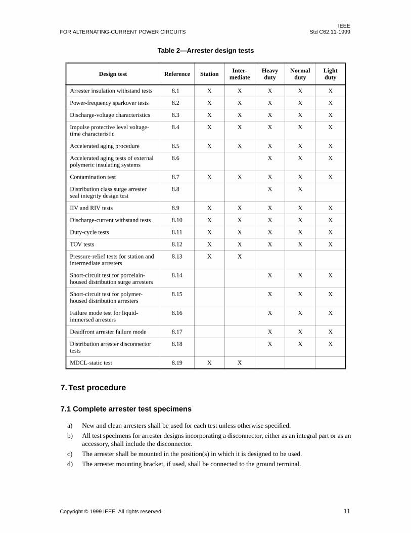
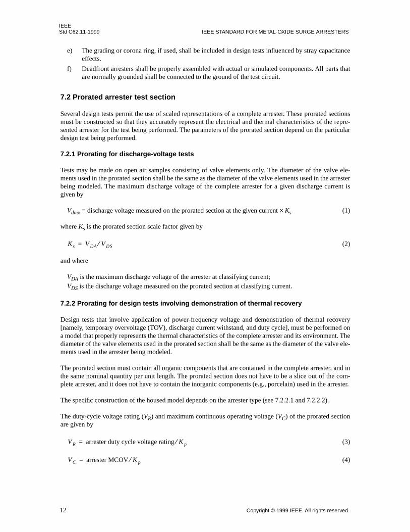


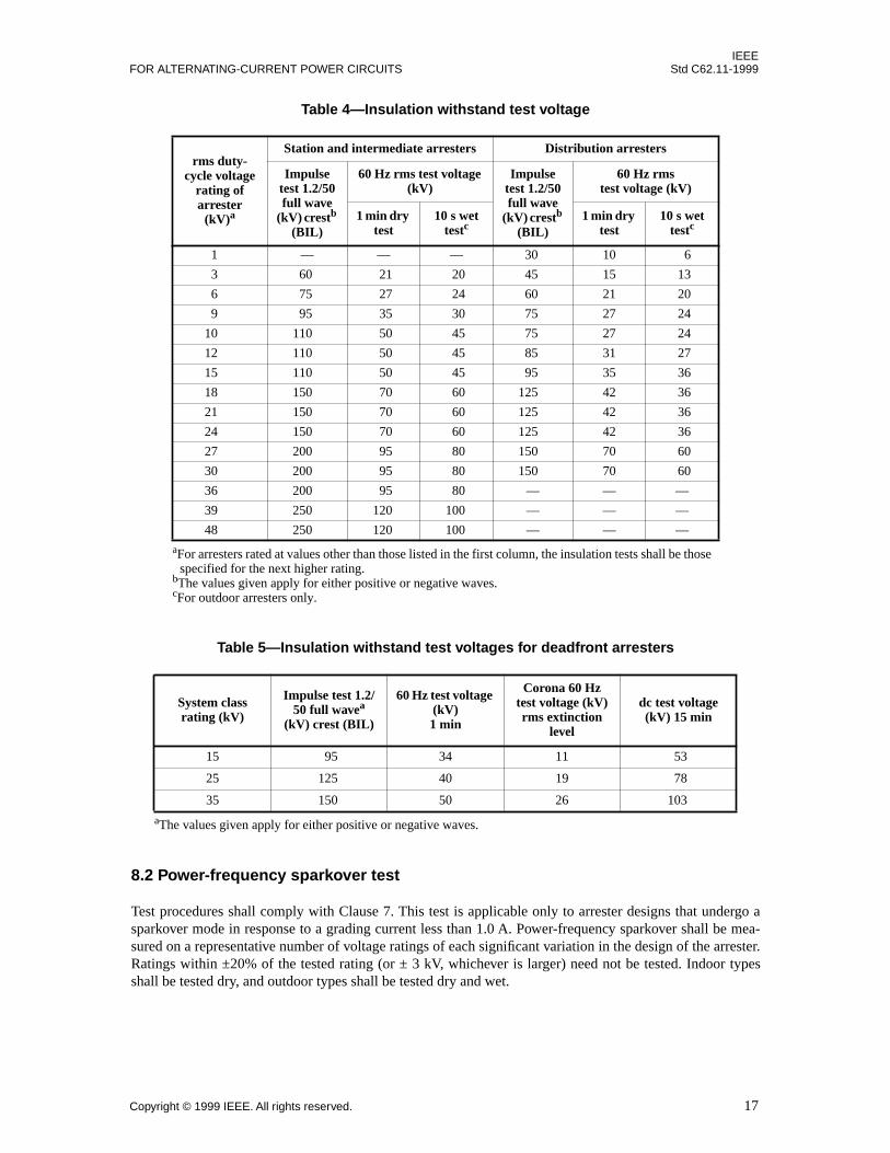
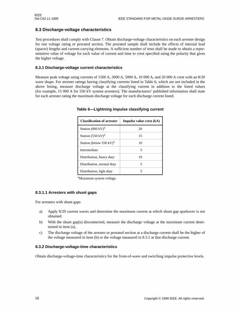

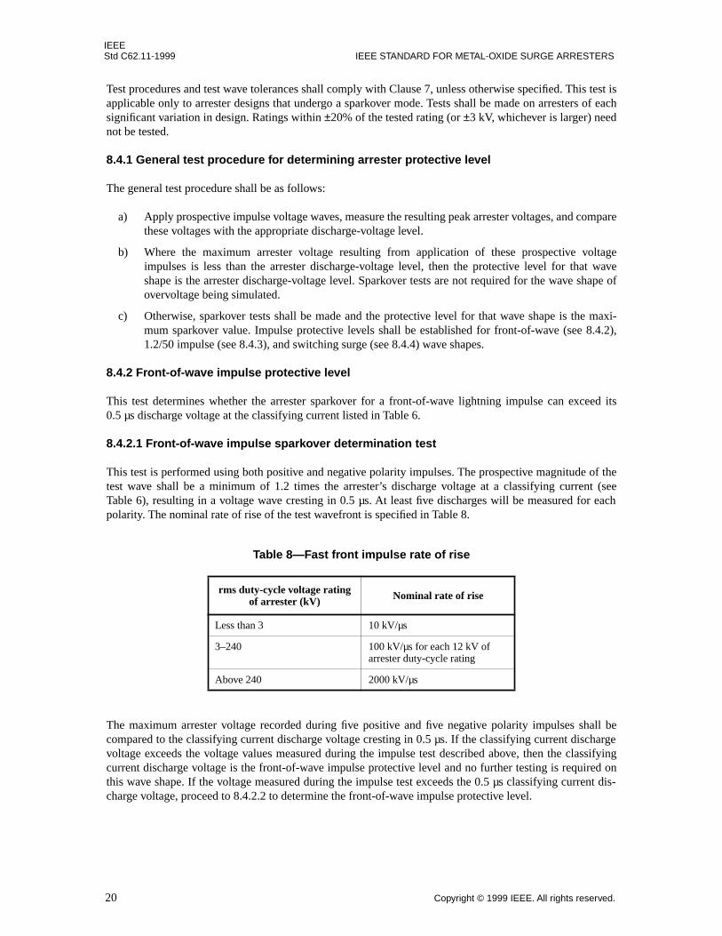


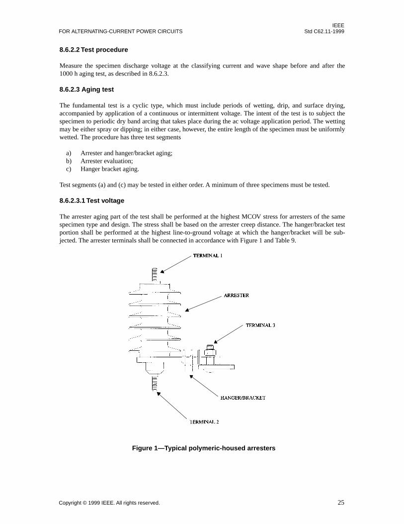
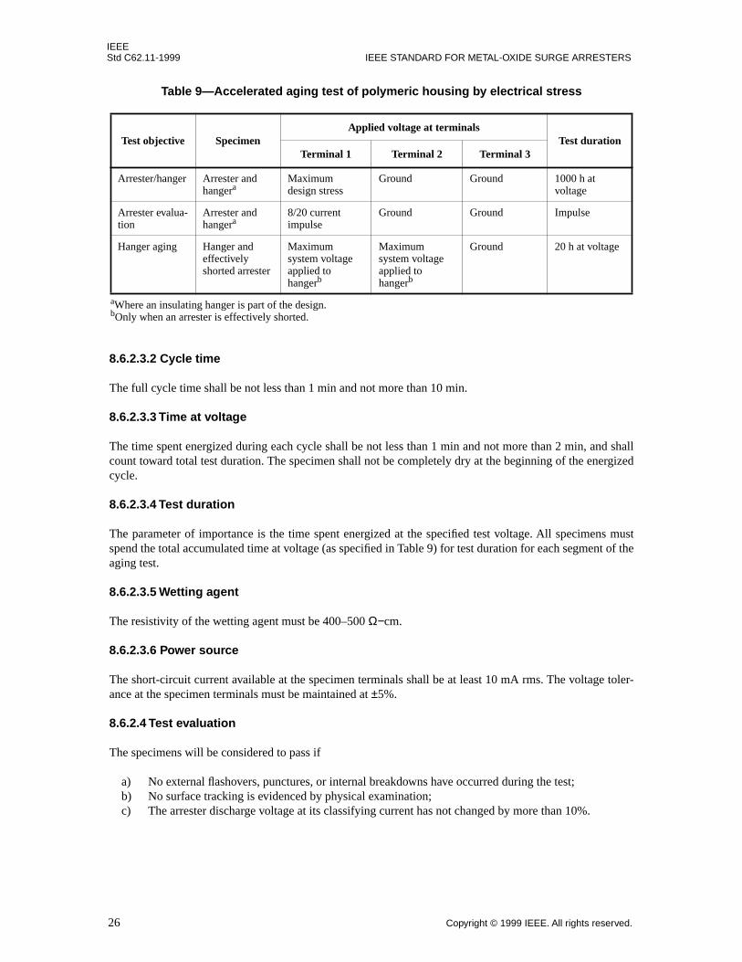


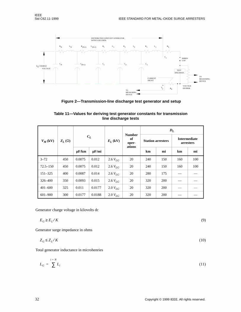


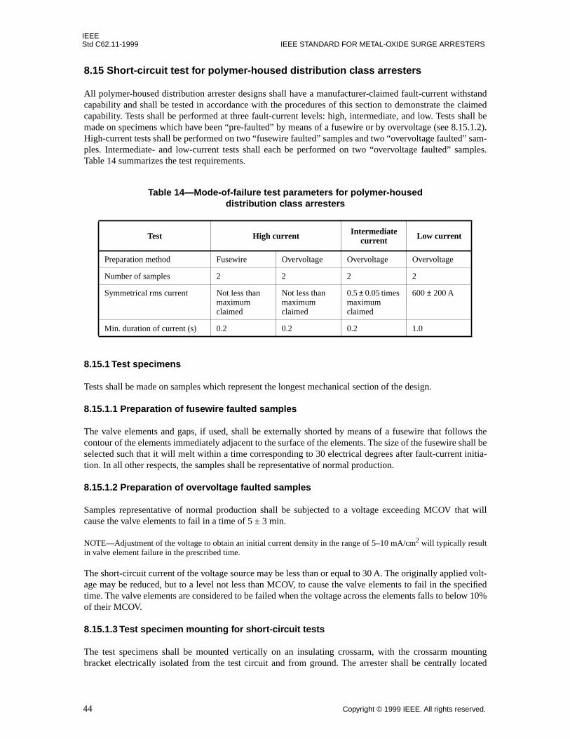


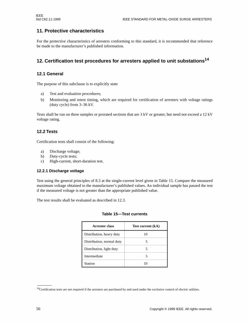


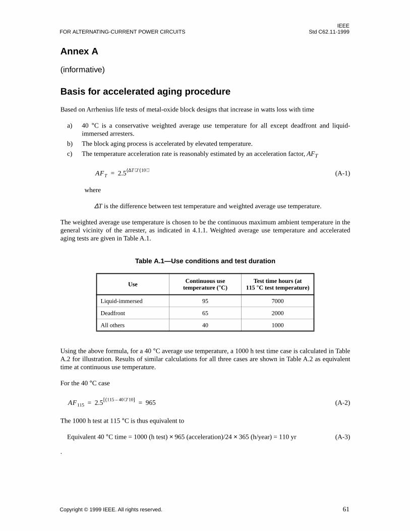
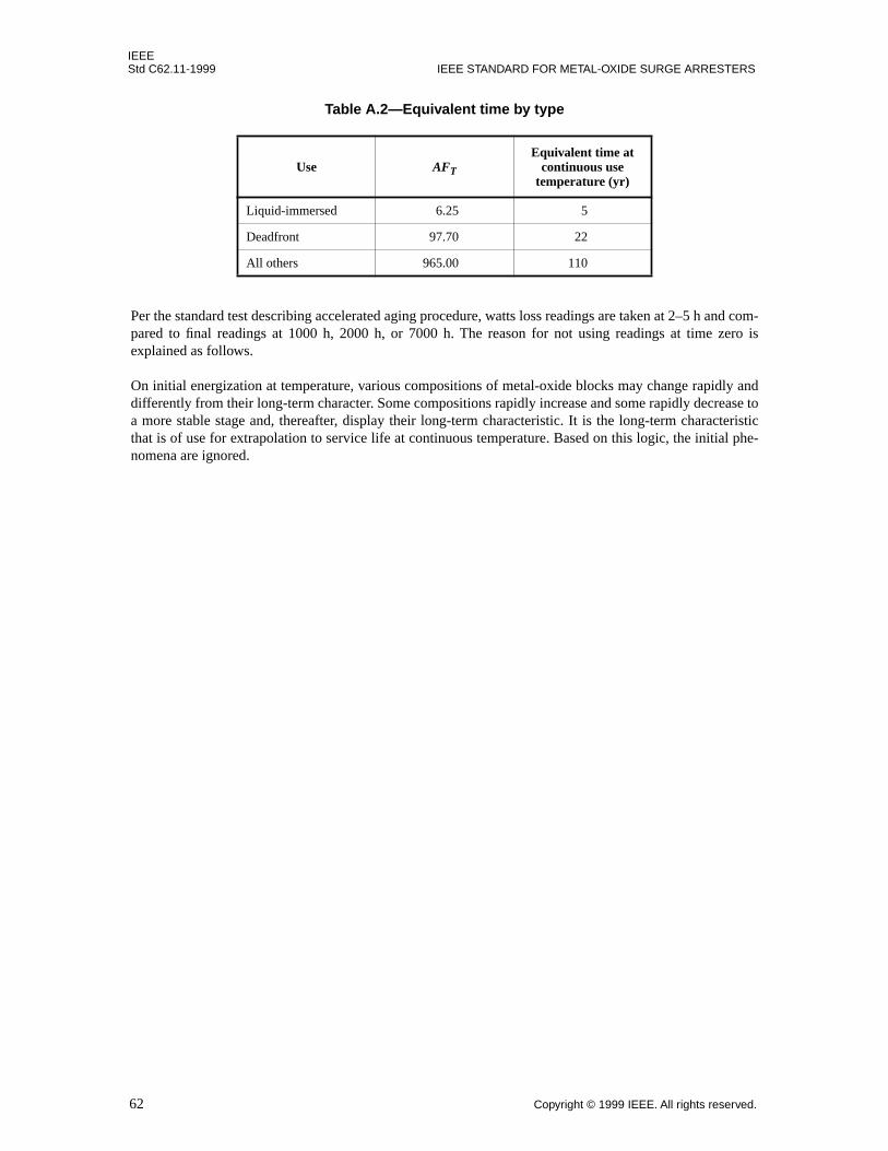
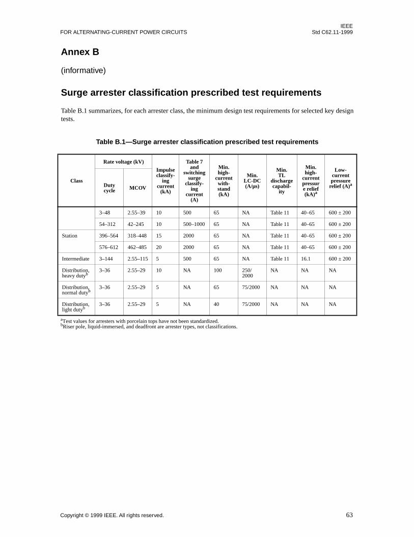


![Energy Division LV and MV Metal-Oxide Surge Arresters · Overview of ZnO surge arresters offered by Tyco Electronics Energy Division Type Rating [kA] Line Application Continuous Page](https://static.documents.pub/doc/80x56/5f048d217e708231d40e87bb/energy-division-lv-and-mv-metal-oxide-surge-overview-of-zno-surge-arresters-offered.jpg)


