96
Authorized licensed use limited to: University of Waterloo. Downloaded on October 13,2016 at 09:26:57 UTC from IEEE Xplore. Restrictions apply.

IEEE Standard Requirements for Instrument Transformers
Sponsored by the Transformers Committee
IEEE 3 Park Avenue New York, NY 10016-5997 USA
IEEE Power and Energy Society
IEEE Std C57.13™-2016 (Revision of
IEEE Std C57.13-2008)
Authorized licensed use limited to: University of Waterloo. Downloaded on October 13,2016 at 09:26:57 UTC from IEEE Xplore. Restrictions apply.
IEEE Std C57.13™-2016 (Revision of
IEEE Std C57.13-2008)
IEEE Standard Requirements for Instrument Transformers
Sponsor Transformers Committee of the IEEE Power and Energy Society Approved 29 January 2016 IEEE-SA Standards Board
Authorized licensed use limited to: University of Waterloo. Downloaded on October 13,2016 at 09:26:57 UTC from IEEE Xplore. Restrictions apply.

Copyright © 2016 IEEE. All rights reserved.
2
Abstract: Electrical, dimensional, and mechanical characteristics are covered, taking into consideration certain safety features, for current and inductively coupled voltage transformers of types generally used in the measurement of electricity and the control of equipment associated with the generation, transmission, and distribution of alternating current. The aim is to provide a basis for performance and interchangeability of equipment covered and to assist in the proper selection of such equipment. Safety precautions are also addressed. Accuracy classes for metering service are provided. The test code covers measurement and calculation of ratio and phase angle, demagnetization, impedance and excitation measurements, polarity determination, resistance measurements, short-time characteristics, temperature rise tests, dielectric tests, and measurement of open-circuit voltage of current transformers. Keywords: accuracy, current transformer, IEEE C57.13™, instrument transformer, primary winding, rated secondary voltage, routine tests, secondary winding, type tests, voltage transformer
•
The Institute of Electrical and Electronics Engineers, Inc. 3 Park Avenue, New York, NY 10016-5997, USA Copyright © 2016 by The Institute of Electrical and Electronics Engineers, Inc. All rights reserved. Published 29 June 2016. Printed in the United States of America. IEEE is a registered trademark in the U.S. Patent & Trademark Office, owned by The Institute of Electrical and Electronics Engineers, Incorporated. PDF: ISBN 978-1-5044-2029-7 STD20943 Print: ISBN 978-1-5044-2030-3 STDPD20943 IEEE prohibits discrimination, harassment, and bullying. For more information, visit http://www.ieee.org/web/aboutus/whatis/policies/p9-26.html. No part of this publication may be reproduced in any form, in an electronic retrieval system or otherwise, without the prior written permission of the publisher.
Authorized licensed use limited to: University of Waterloo. Downloaded on October 13,2016 at 09:26:57 UTC from IEEE Xplore. Restrictions apply.

Copyright © 2016 IEEE. All rights reserved.
3
Important Notices and Disclaimers Concerning IEEE Standards Documents IEEE documents are made available for use subject to important notices and legal disclaimers. These notices and disclaimers, or a reference to this page, appear in all standards and may be found under the heading “Important Notice” or “Important Notices and Disclaimers Concerning IEEE Standards Documents.”
Notice and Disclaimer of Liability Concerning the Use of IEEE Standards Documents
IEEE Standards documents (standards, recommended practices, and guides), both full-use and trial-use, are developed within IEEE Societies and the Standards Coordinating Committees of the IEEE Standards Association (“IEEE-SA”) Standards Board. IEEE (“the Institute”) develops its standards through a consensus development process, approved by the American National Standards Institute (“ANSI”), which brings together volunteers representing varied viewpoints and interests to achieve the final product. Volunteers are not necessarily members of the Institute and participate without compensation from IEEE. While IEEE administers the process and establishes rules to promote fairness in the consensus development process, IEEE does not independently evaluate, test, or verify the accuracy of any of the information or the soundness of any judgments contained in its standards.
IEEE does not warrant or represent the accuracy or content of the material contained in its standards, and expressly disclaims all warranties (express, implied and statutory) not included in this or any other document relating to the standard, including, but not limited to, the warranties of: merchantability; fitness for a particular purpose; non-infringement; and quality, accuracy, effectiveness, currency, or completeness of material. In addition, IEEE disclaims any and all conditions relating to: results; and workmanlike effort. IEEE standards documents are supplied “AS IS” and “WITH ALL FAULTS.”
Use of an IEEE standard is wholly voluntary. The existence of an IEEE standard does not imply that there are no other ways to produce, test, measure, purchase, market, or provide other goods and services related to the scope of the IEEE standard. Furthermore, the viewpoint expressed at the time a standard is approved and issued is subject to change brought about through developments in the state of the art and comments received from users of the standard.
In publishing and making its standards available, IEEE is not suggesting or rendering professional or other services for, or on behalf of, any person or entity nor is IEEE undertaking to perform any duty owed by any other person or entity to another. Any person utilizing any IEEE Standards document, should rely upon his or her own independent judgment in the exercise of reasonable care in any given circumstances or, as appropriate, seek the advice of a competent professional in determining the appropriateness of a given IEEE standard.
IN NO EVENT SHALL IEEE BE LIABLE FOR ANY DIRECT, INDIRECT, INCIDENTAL, SPECIAL, EXEMPLARY, OR CONSEQUENTIAL DAMAGES (INCLUDING, BUT NOT LIMITED TO: PROCUREMENT OF SUBSTITUTE GOODS OR SERVICES; LOSS OF USE, DATA, OR PROFITS; OR BUSINESS INTERRUPTION) HOWEVER CAUSED AND ON ANY THEORY OF LIABILITY, WHETHER IN CONTRACT, STRICT LIABILITY, OR TORT (INCLUDING NEGLIGENCE OR OTHERWISE) ARISING IN ANY WAY OUT OF THE PUBLICATION, USE OF, OR RELIANCE UPON ANY STANDARD, EVEN IF ADVISED OF THE POSSIBILITY OF SUCH DAMAGE AND REGARDLESS OF WHETHER SUCH DAMAGE WAS FORESEEABLE.
Translations The IEEE consensus development process involves the review of documents in English only. In the event that an IEEE standard is translated, only the English version published by IEEE should be considered the approved IEEE standard.
Authorized licensed use limited to: University of Waterloo. Downloaded on October 13,2016 at 09:26:57 UTC from IEEE Xplore. Restrictions apply.

Copyright © 2016 IEEE. All rights reserved.
4
Official statements
A statement, written or oral, that is not processed in accordance with the IEEE-SA Standards Board Operations Manual shall not be considered or inferred to be the official position of IEEE or any of its committees and shall not be considered to be, or be relied upon as, a formal position of IEEE. At lectures, symposia, seminars, or educational courses, an individual presenting information on IEEE standards shall make it clear that his or her views should be considered the personal views of that individual rather than the formal position of IEEE.
Comments on standards Comments for revision of IEEE Standards documents are welcome from any interested party, regardless of membership affiliation with IEEE. However, IEEE does not provide consulting information or advice pertaining to IEEE Standards documents. Suggestions for changes in documents should be in the form of a proposed change of text, together with appropriate supporting comments. Since IEEE standards represent a consensus of concerned interests, it is important that any responses to comments and questions also receive the concurrence of a balance of interests. For this reason, IEEE and the members of its societies and Standards Coordinating Committees are not able to provide an instant response to comments or questions except in those cases where the matter has previously been addressed. For the same reason, IEEE does not respond to interpretation requests. Any person who would like to participate in revisions to an IEEE standard is welcome to join the relevant IEEE working group.
Comments on standards should be submitted to the following address:
Secretary, IEEE-SA Standards Board 445 Hoes Lane Piscataway, NJ 08854 USA
Laws and regulations
Users of IEEE Standards documents should consult all applicable laws and regulations. Compliance with the provisions of any IEEE Standards document does not imply compliance to any applicable regulatory requirements. Implementers of the standard are responsible for observing or referring to the applicable regulatory requirements. IEEE does not, by the publication of its standards, intend to urge action that is not in compliance with applicable laws, and these documents may not be construed as doing so
Copyrights
IEEE draft and approved standards are copyrighted by IEEE under U.S. and international copyright laws. They are made available by IEEE and are adopted for a wide variety of both public and private uses. These include both use, by reference, in laws and regulations, and use in private self-regulation, standardization, and the promotion of engineering practices and methods. By making these documents available for use and adoption by public authorities and private users, IEEE does not waive any rights in copyright to the documents.
Photocopies
Subject to payment of the appropriate fee, IEEE will grant users a limited, non-exclusive license to photocopy portions of any individual standard for company or organizational internal use or individual, non-commercial use only. To arrange for payment of licensing fees, please contact Copyright Clearance Center, Customer Service, 222 Rosewood Drive, Danvers, MA 01923 USA; +1 978 750 8400. Permission to photocopy portions of any individual standard for educational classroom use can also be obtained through the Copyright Clearance Center.
Authorized licensed use limited to: University of Waterloo. Downloaded on October 13,2016 at 09:26:57 UTC from IEEE Xplore. Restrictions apply.

Copyright © 2016 IEEE. All rights reserved.
5
Updating of IEEE Standards documents Users of IEEE Standards documents should be aware that these documents may be superseded at any time by the issuance of new editions or may be amended from time to time through the issuance of amendments, corrigenda, or errata. An official IEEE document at any point in time consists of the current edition of the document together with any amendments, corrigenda, or errata then in effect.
Every IEEE standard is subjected to review at least every ten years. When a document is more than ten years old and has not undergone a revision process, it is reasonable to conclude that its contents, although still of some value, do not wholly reflect the present state of the art. Users are cautioned to check to determine that they have the latest edition of any IEEE standard.
In order to determine whether a given document is the current edition and whether it has been amended through the issuance of amendments, corrigenda, or errata, visit the IEEE-SA Website at http://ieeexplore.ieee.org/Xplore/home.jsp or contact IEEE at the address listed previously. For more information about the IEEE SA or IEEE’s standards development process, visit the IEEE-SA Website at http://standards.ieee.org.
Errata
Errata, if any, for all IEEE standards can be accessed on the IEEE-SA Website at the following URL: http://standards.ieee.org/findstds/errata/index.html. Users are encouraged to check this URL for errata periodically.
Patents
Attention is called to the possibility that implementation of this standard may require use of subject matter covered by patent rights. By publication of this standard, no position is taken by the IEEE with respect to the existence or validity of any patent rights in connection therewith. If a patent holder or patent applicant has filed a statement of assurance via an Accepted Letter of Assurance, then the statement is listed on the IEEE-SA Website at http://standards.ieee.org/about/sasb/patcom/patents.html. Letters of Assurance may indicate whether the Submitter is willing or unwilling to grant licenses under patent rights without compensation or under reasonable rates, with reasonable terms and conditions that are demonstrably free of any unfair discrimination to applicants desiring to obtain such licenses.
Essential Patent Claims may exist for which a Letter of Assurance has not been received. The IEEE is not responsible for identifying Essential Patent Claims for which a license may be required, for conducting inquiries into the legal validity or scope of Patents Claims, or determining whether any licensing terms or conditions provided in connection with submission of a Letter of Assurance, if any, or in any licensing agreements are reasonable or non-discriminatory. Users of this standard are expressly advised that determination of the validity of any patent rights, and the risk of infringement of such rights, is entirely their own responsibility. Further information may be obtained from the IEEE Standards Association.
Authorized licensed use limited to: University of Waterloo. Downloaded on October 13,2016 at 09:26:57 UTC from IEEE Xplore. Restrictions apply.
6 Copyright © 2016 IEEE. All rights reserved.
Participants
At the time this IEEE standard was completed, the Requirements for Instrument Transformers Working Group had the following membership:
Ross McTaggart, Chair Thomas Sizemore, Vice Chair
Fred Elliott Marcel Fortin Rolando Gomez Michael Haas Nathan Jacob Vladimir Khalin Marek Kornowski Brian Leslie Nigel MacDonald
James McBride Scott McCloskey Paul Millward Randolph Mullikin Rudolf Ogajanov Adnan Rashid Pierre Riffon Zoltan Roman
Steven Snyder Eddy So Adam Strader Richard vonGrimmingen Deiter Wagner David Wallace Barrett Wimberly Peter Zhao
The following members of the individual balloting committee voted on this standard. Balloters may have voted for approval, disapproval, or abstention.
Roy Alexander Ficheux Arnaud Thomas Barnes Barry Beaster Wallace Binder Thomas Blackburn Carl Bush Thomas Callsen Paul Cardinal John Crouse Gary Donner Randall Dotson Donald Dunn Douglas J. Edwards Fred Elliott Jorge Fernandez Daher Namal Fernando Keith Flowers Paul Forquer Marcel Fortin Frank Gerleve David Giegel David Gilmer Jalal Gohari Edwin Goodwin James Graham Randall Groves Ajit Gwal Michael Haas John Harley David Harris Roger Hedding Jeffrey Helzer Robert Hoerauf Jill Holmes Philip Hopkinson
Richard Jackson Ali Naderian Jahromi John John Gerald Johnson Wayne Johnson Laszlo Kadar Innocent Kamwa Gael Kennedy Vladimir Khalin Yuri Khersonsky James Kinney Hermann Koch Boris Kogan Marek Kornowski Jim Kulchisky Saumen Kundu Chung-Yiu Lam Brian Leslie Albert Livshitz Thomas Lundquist Nigel MacDonald Bruce Magruder J.Dennis Marlow Lee Matthews Omar Mazzoni John McClelland Mark McNally Ross McTaggart John Miller Sujeet Mishra Georges Montillet Thomas Mulcahy Daniel Mulkey Randolph Mullikin Jerry Murphy Edrin Murzaku
Bruce Muschlitz Ryan Musgrove K. R. M. Nair Dennis Neitzel Arthur Neubauer Michael Newman Joe Nims James O’Brien Rudolf Ogajanov T. W. Olsen Lorraine Padden Mirko Palazzo Bansi Patel Dhiru Patel Brian Penny Christopher Petrola Donald Platts Alvaro Portillo Tom Prevost Iulian Profir Ulf Radbrandt Samala Santosh Reddy Johannes Rickmann Pierre Riffon Michael Roberts Charles Rogers Zoltan Roman Thomas Rozek Steven Sano Daniel Sauer Bartien Sayogo Devki Sharma Hyeong Sim Charles Simmons Thomas Sizemore Jerry Smith
Authorized licensed use limited to: University of Waterloo. Downloaded on October 13,2016 at 09:26:57 UTC from IEEE Xplore. Restrictions apply.

7 Copyright © 2016 IEEE. All rights reserved.
Steven Snyder David Stankes David Tepen Roger Verdolin John Vergis
Jane Verner David Wallace David Wallach D. Weers Kenneth White
Barrett Wimberly Jian Yu Peter Zhao Xi Zhu
When the IEEE-SA Standards Board approved this standard on 29 January 2016, it had the following membership:
Jean-Philippe Faure, Chair Vacant Position, Vice Chair
John Kulick, Past Chair Konstantinos Karachalios, Secretary
Chuck Adams Masayuki Ariyoshi Ted Burse Stephen Dukes Jianbin Fan J. Travis Griffith Gary Hoffman
Ronald W. Hotchkiss Michael Janezik Joseph L. Koepfinger* Hung Ling Kevin Lu Annette D. Reilly Gary Robinson
Mehmet Ulema Yingli Wen Howard Wolfman Don Wright Yu Yuan Daidi Zhong
*Member Emeritus
Authorized licensed use limited to: University of Waterloo. Downloaded on October 13,2016 at 09:26:57 UTC from IEEE Xplore. Restrictions apply.

8 Copyright © 2016 IEEE. All rights reserved.
Introduction
This introduction is not part of IEEE Std C57.13™-2016, IEEE Standard Requirements for Instrument Transformers.
This standard was prepared by the Instrument Transformer Subcommittee of the Transformers Committee of the IEEE Power and Energy Society. The purpose of this standard is to cover the electrical, dimensional, and mechanical characteristics and to take into consideration certain safety features, for current and inductively coupled voltage transformers.
The changes in this revision of IEEE Std C57.13 include revised partial discharge requirements, the addition of Annex B, covering bushing current transformers and two classes of instrument transformer requirements have been introduced. In addition, this standard has been reorganized to make it more understandable. The accuracy requirements from IEEE Std C57.13.6™ have also been incorporated into the standard.1
1 Information on references can be found in Clause 2.
Authorized licensed use limited to: University of Waterloo. Downloaded on October 13,2016 at 09:26:57 UTC from IEEE Xplore. Restrictions apply.

9 Copyright © 2016 IEEE. All rights reserved.
Contents
1. Overview ...................................................................................................................................................11 1.1 Scope ..................................................................................................................................................11 1.2 Purpose ...............................................................................................................................................11
2. Normative references .................................................................................................................................12
3. Definitions .................................................................................................................................................12
4. General requirements .................................................................................................................................13 4.1 Service conditions ...............................................................................................................................13 4.2 Effect of air density on flashover voltage ...........................................................................................14 4.3 Frequency ...........................................................................................................................................15 4.4 Effect of altitude on temperature rise and effect of ambient temperature on permissible loading ......15 4.5 Basic impulse insulation levels, dielectric tests, and outdoor instrument transformer creepage distance and wet test .................................................................................................................................16 4.6 Temperature rise .................................................................................................................................19 4.7 Capacitance and dissipation factor requirements ................................................................................20 4.8 Classification of tests ..........................................................................................................................20 4.9 Construction .......................................................................................................................................22
5. Accuracy classes for metering ...................................................................................................................25 5.1 Basis for accuracy classes ...................................................................................................................25 5.2 Expression of transformer correction factor at 0.6 power factor (lagging) of metered load ...............26 5.3 Standard accuracy classes ...................................................................................................................26 5.4 Limiting values of ratio correction factor and phase angle for standard accuracy classes ..................27
6. Current transformers ..................................................................................................................................30 6.1 Terms in which ratings shall be expressed .........................................................................................30 6.2 Standard burdens ................................................................................................................................30 6.3 Accuracy ratings for metering ............................................................................................................30 6.4 Accuracy ratings for relaying .............................................................................................................32 6.5 Continuous thermal current rating factors based on 30 °C average ambient air temperature .............34 6.6 Short-time current ratings ...................................................................................................................34 6.7 Secondary winding-induced voltages .................................................................................................35 6.8 Nameplates .........................................................................................................................................36 6.9 Terminals ............................................................................................................................................36 6.10 Application data ................................................................................................................................36 6.11 Routine accuracy tests ......................................................................................................................39
7. Voltage transformers .................................................................................................................................40 7.1 Terms in which ratings shall be expressed .........................................................................................40 7.2 Standard burdens ................................................................................................................................44 7.3 Accuracy ratings .................................................................................................................................45 7.4 Thermal burden ratings .......................................................................................................................45 7.5 Nameplates .........................................................................................................................................46 7.6 Terminals ............................................................................................................................................46 7.7 Short-circuit capability .......................................................................................................................46 7.8 Application data ..................................................................................................................................47 7.9 Induced voltage test ............................................................................................................................47 7.10 Routine accuracy tests ......................................................................................................................47
Authorized licensed use limited to: University of Waterloo. Downloaded on October 13,2016 at 09:26:57 UTC from IEEE Xplore. Restrictions apply.

10 Copyright © 2016 IEEE. All rights reserved.
8. Test procedures applicable to instrument transformers .............................................................................47 8.1 Ratio and phase angle measurement and calculations ........................................................................48 8.2 Impedance, excitation, and composite error measurements ................................................................49 8.3 Polarity ...............................................................................................................................................52 8.4 Resistance measurements ...................................................................................................................53 8.5 Dielectric tests ....................................................................................................................................55 8.6 Partial discharge measurement ...........................................................................................................57
9. Test procedures applicable to current transformers ...................................................................................59 9.1 Ratio and phase angle measurement and calculations ........................................................................59 9.2 Demagnetization .................................................................................................................................63 9.3 Impedance measurements ...................................................................................................................64 9.4 Polarity ...............................................................................................................................................65
10. Test procedures applicable to voltage transformers.................................................................................66 10.1 Ratio and phase angle measurement and calculations ......................................................................66 10.2 Impedance measurements .................................................................................................................68 10.3 Polarity .............................................................................................................................................69
11. Type test procedures applicable to instrument transformers ...................................................................70 11.1 Short-time characteristics .................................................................................................................70 11.2 Temperature rise tests .......................................................................................................................72 11.3 Impulse tests .....................................................................................................................................75 11.4 Partial discharge measurement .........................................................................................................77 11.5 Wet voltage withstand tests ..............................................................................................................78 11.6 Ground shield check—72kV class and above ..................................................................................79
12. Type test procedures applicable to current transformers .........................................................................79 12.1 Short-time thermal rating of current transformers ............................................................................79 12.2 Current transformer temperature rise tests ........................................................................................80 12.3 Inter-turn overvoltage test .................................................................................................................80
13. Type test procedures applicable to voltage transformers .........................................................................81 13.1 Short-circuit thermal capability of voltage transformers ..................................................................81 13.2 Voltage transformer temperature rise tests .......................................................................................82
Annex A (informative) Bibliography ............................................................................................................83
Annex B (normative) Bushing-type current transformer (BCT) and special purpose window type current transformers ...................................................................................................................................................86
B.1 Introduction ........................................................................................................................................86 B.2 Scope ..................................................................................................................................................86 B.3 General requirements .........................................................................................................................86 B.4 Continuous thermal ratings ................................................................................................................88 B.5 Short-time ratings ...............................................................................................................................90 B.6 Dielectric consideration .....................................................................................................................90 B.7 Construction .......................................................................................................................................90 B.8 Routine tests .......................................................................................................................................92 B.9 Type tests ...........................................................................................................................................93 B.10 Installation .......................................................................................................................................93 B.11 Field tests .........................................................................................................................................94 B.12 Bushing linear coupler (BLC) ..........................................................................................................94
Authorized licensed use limited to: University of Waterloo. Downloaded on October 13,2016 at 09:26:57 UTC from IEEE Xplore. Restrictions apply.

11 Copyright © 2016 IEEE. All rights reserved.
IEEE Standard Requirements for Instrument Transformers
IMPORTANT NOTICE: IEEE Standards documents are not intended to ensure safety, security, health, or environmental protection, or ensure against interference with or from other devices or networks. Implementers of IEEE Standards documents are responsible for determining and complying with all appropriate safety, security, environmental, health, and interference protection practices and all applicable laws and regulations.
This IEEE document is made available for use subject to important notices and legal disclaimers. These notices and disclaimers appear in all publications containing this document and may be found under the heading “Important Notice” or “Important Notices and Disclaimers Concerning IEEE Documents.” They can also be obtained on request from IEEE or viewed at http://standards.ieee.org/IPR/disclaimers.html.
1. Overview
1.1 Scope
This standard is intended for use as a basis for performance and interchangeability of equipment covered, and to assist in the proper selection of such equipment. Safety precautions are also addressed.
This standard covers certain electrical, dimensional, and mechanical characteristics, and takes into consideration certain safety features of current and inductively coupled voltage transformers of types generally used in the measurement of electricity and the control.
1.2 Purpose
The purpose of this standard is to provide the performance requirements for electrical system and test interchangeability of current and inductively coupled voltage transformers. These transformers are for both indoor and outdoor application.
This standard covers the requirements for Class 1 instrument transformers. For instrument transformers of a nominal system voltage of 115 kV and above if Class 2 is required refer to IEEE Std C57.13.5™.1
1 Information on references can be found in Clause 2.
Authorized licensed use limited to: University of Waterloo. Downloaded on October 13,2016 at 09:26:57 UTC from IEEE Xplore. Restrictions apply.

IEEE Std C57.13-2016 IEEE Standard for Requirements for Instrument Transformers
12 Copyright © 2016 IEEE. All rights reserved.
2. Normative references
The following referenced documents are indispensable for the application of this document (i.e., they must be understood and used, so each referenced document is cited in text and its relationship to this document is explained). For dated references, only the edition cited applies. For undated references, the latest edition of the referenced document (including any amendments or corrigenda) applies.
IEC 60270, High-voltage test techniques—Partial discharge measurements.2
IEC 61869-2, Instrument Transformers—Part 2: Additional Requirements for Current Transformers.
IEEE Std 4™, IEEE Standard for High-Voltage Testing Techniques.3, 4
IEEE Std 693™, IEEE Recommended Practice for Seismic Design of Substations.
IEEE Std C37.04™, IEEE Standard Rating Structure for AC High-Voltage Circuit Breakers.
IEEE Std C37.09™, IEEE Standard Test Procedure for AC High-Voltage Circuit Breakers Rated on a Symmetrical Basis.
IEEE Std C57.12.00™, IEEE Standard General Requirements for Liquid-Immersed Distribution, Power, and Regulating Transformers.
IEEE Std C57.12.90™, IEEE Standard Test Code for Liquid-Immersed Distribution, Power, and Regulating Transformers.
IEEE Std C57.13.5™, IEEE Standard of Performance and Test Requirements for Instrument Transformers of a Nominal System Voltage of 115 kV and Above.
IEEE Std C57.13.6™, IEEE Standard for High-Accuracy Instrument Transformers.
IEEE Std C57.19.00™, IEEE Standard General Requirements and Test Procedure for Power Apparatus Bushings.
3. Definitions
For the purposes of this document, the following terms and definitions apply. The IEEE Standards Dictionary Online should be consulted for terms not defined in this clause.5
class 1 instrument transformer: An instrument transformer that is constructed and tested in accordance with this standard.
class 2 instrument transformer: An instrument transformer that is constructed and tested in accordance with IEEE Std C57.13.5™.
gapped core: A core where the magnetic core has an intentional gap filled with non-magnetic material.
2 IEC publications are available from the International Electrotechnical Commission (http://www.iec.ch/). IEC publications are also available in the United States from the American National Standards Institute (http://www.ansi.org/). 3 IEEE publications are available from the Institute of Electrical and Electronics Engineers, 445 Hoes Lane, Piscataway, NJ 08854, USA (http://standards/ieee.org/). 4 The IEEE standards or products referred to in this clause are trademarks of the Institute of Electrical and Electronics Engineers, Inc. 5 IEEE Standards Dictionary Online subscription is available at: http://ieeexplore.ieee.org/xpls/dictionary.jsp.
Authorized licensed use limited to: University of Waterloo. Downloaded on October 13,2016 at 09:26:57 UTC from IEEE Xplore. Restrictions apply.

IEEE Std C57.13-2016 IEEE Standard for Requirements for Instrument Transformers
13 Copyright © 2016 IEEE. All rights reserved.
indoor voltage transformer: One that, because of its construction, shall be protected from the weather.
prescribed extinction voltage: The minimum voltage at which the reference partial discharge intensity shall be met when the voltage applied to the transformer is gradually decreased without interruption from the power frequency withstand voltage or pre-stress voltage value during the partial discharge test.
partial discharge inception voltage: The lowest voltage at which partial discharges exceeding a specified level are observed under specified conditions when the voltage applied to the test object is gradually increased from a lower value.
4. General requirements
4.1 Service conditions
4.1.1 Unusual temperature and altitude service conditions
Instrument transformers conforming to this standard shall be suitable for operation at their thermal ratings, provided that the altitude does not exceed 1000 m.
The minimum ambient air temperature is –30 °C for outdoor applications and –5 °C for indoor applications.
4.1.1.1 30 ºC average ambient temperature
If the transformers are air cooled, the ambient temperature of the cooling air does not exceed 40 °C and the average ambient temperature of the cooling air for any 24-hour period does not exceed 30 °C.6
4.1.1.2 55 ºC average ambient temperature
Instrument transformers may also be given ratings for operation in 55 °C average ambient temperature, with maximum ambient air temperature not exceeding 65 °C.
4.1.2 Unusual temperature and altitude service conditions
Instrument transformers may be applied at higher altitudes or higher ambient temperatures than specified in 4.1.1, but the performance may be affected and special consideration should be given to these applications (see 4.2 and 4.4).
NOTE—For applications involving bushing-type current transformers, see Annex B.7
6 It is recommended that the average temperature of the cooling air be calculated by averaging 24 consecutive hourly readings. When the outdoor air is the cooling medium, the average of the maximum and minimum daily temperature may be used. The value that is obtained in this manner is usually higher than the true daily average by not more than 1/2 °C. 7 Notes in text, tables, and figures of a standard are given for information only and do not contain requirements needed to implement this standard.
Authorized licensed use limited to: University of Waterloo. Downloaded on October 13,2016 at 09:26:57 UTC from IEEE Xplore. Restrictions apply.

IEEE Std C57.13-2016 IEEE Standard for Requirements for Instrument Transformers
14 Copyright © 2016 IEEE. All rights reserved.
4.1.3 Other conditions that may affect design and application
Where conditions other than those discussed in 4.1.1 or 4.1.2 exist, they should be brought to the attention of those responsible for the design and application of instrument transformers. Examples of these conditions are as follows:
a) Damaging fumes or vapors, excessive or abrasive dust, explosive mixtures of dust or gases, steam, salt spray, excessive moisture or dripping water, etc.
b) Abnormal vibrations, shocks, or tilting.
c) Ambient temperatures above 55 °C or below –30 °C.
d) Unusual transportation or storage conditions.
e) Unusual space limitations or restricted ventilation.
f) Unusual duty, frequency of operation, difficulty of maintenance, poor wave form, unbalanced voltage, special insulation requirements, etc.
g) Applications in switchgear assemblies, including metal enclosed bus.*
h) Applications with high-voltage power circuit breakers.*
i) Applications with power transformers.*
j) Applications with outdoor bushings.*
k) For altitudes below sea level or buried underground.*
l) Seismic conditions: For seismic qualification methods refer to IEEE Std 693.
*For applications involving bushing-type current transformers, see Annex B.
4.2 Effect of air density on flashover voltage
The effect of decreased air density is to decrease the flashover voltage for a given flashover distance. See IEEE Std 4 for use of a correction factor.
The dielectric strength of air decreases as altitude increases. Dielectric strength that depends on air should be multiplied by the proper altitude correction factor to obtain the dielectric strength at the required altitude (see Table 1). For an altitude exceeding 3000 m, caution should be exercised.
Authorized licensed use limited to: University of Waterloo. Downloaded on October 13,2016 at 09:26:57 UTC from IEEE Xplore. Restrictions apply.

IEEE Std C57.13-2016 IEEE Standard for Requirements for Instrument Transformers
15 Copyright © 2016 IEEE. All rights reserved.
Table 1 —Dielectric strength correction factors for altitudes greater than 1000 m
Altitude (m)
Altitude correction factor for dielectric strength
1000 1.00
1200 0.98
1500 0.95
1800 0.92
2100 0.89
2400 0.86
2700 0.83
3000 0.80
3600 0.75
4200 0.70
4500a 0.67
NOTE 1— Intermediate values may be obtained by interpolation. NOTE 2— This table considers the effect of decreased air density due to decreased air pressure.
aAn altitude of 4500 m is considered a maximum for instrument transformers conforming to this standard.
4.3 Frequency
Instrument transformers shall be designed and rated for operation at a frequency of 60 Hz.
4.4 Effect of altitude on temperature rise and effect of ambient temperature on permissible loading
4.4.1 Loading of current transformers at less than rated current at high altitudes
Current transformers may be operated at altitudes greater than 1000 m without exceeding established temperature limits provided the current is reduced below rated (or below rated times continuous thermal current rating factor) by 0.3% for each 100 m that the altitude exceeds 1000 m.
4.4.2 Operation of current transformers at other than 30 °C ambient temperature
Current transformers designed for 55 °C temperature rise above 30 °C average ambient air temperature may be loaded in accordance with the curves shown in Figure 1 for any given average cooling air temperature and continuous thermal current rating factor. The percent of rated primary current that can be carried continuously without causing established temperature limits to be exceeded is given by the curves. For example, a transformer with a continuous thermal current rating factor (RF) of 2.0 at 30 °C ambient temperature can be used at approximately 150% of rated current at an ambient temperature of 55 °C.
Refer to Annex B for use of bushing-type current transformers in ambient temperatures of 90 °C in hot oil.
Authorized licensed use limited to: University of Waterloo. Downloaded on October 13,2016 at 09:26:57 UTC from IEEE Xplore. Restrictions apply.

IEEE Std C57.13-2016 IEEE Standard for Requirements for Instrument Transformers
16 Copyright © 2016 IEEE. All rights reserved.
4.4.3 Loading of voltage transformers at higher altitudes or higher ambient temperatures
For safety reasons, voltage transformers can be operated at higher altitudes or higher ambient temperatures only after consultation with the manufacturer, because a large percentage of the temperature rise may be due to iron loss, which varies widely with design.
4.5 Basic impulse insulation levels, dielectric tests, and outdoor instrument transformer creepage distance and wet test
An instrument transformer shall be assigned a basic impulse insulation level (BIL) to indicate the factory dielectric tests that the transformer is capable of withstanding.
With the following exceptions, basic impulse insulation voltages, applied voltage test voltages for primary winding insulation, and creepage distances and wet tests for outdoor instrument transformers are listed in Table 2 and Table 3:
a) Applied voltage tests for primary winding insulation are not required on grounded-neutral-terminal-type voltage transformers.
b) For insulated-neutral-terminal-type voltage transformers, the applied voltage test for primary winding insulation shall be 19 kV on outdoor types with BILs greater than 110 kV. On indoor types, and on outdoor types with BILs of 110 kV or less, the test voltage shall be 10 kV.
c) There is no BIL requirement on the neutral terminal of grounded-neutral- or insulated-neutral-terminal-type voltage transformers.
d) The applied voltage test for secondary winding insulation and between multiple secondary windings shall be 2.5 kV.
e) The applied voltage test for autotransformers for use in the secondary circuits of instrument transformers shall be 2.5 kV.
f) The applied voltage test for the primary insulation of auxiliary instrument transformers (for use in the secondary circuits of instrument transformers) shall be 2.5 kV.
Authorized licensed use limited to: University of Waterloo. Downloaded on October 13,2016 at 09:26:57 UTC from IEEE Xplore. Restrictions apply.

IEEE Std C57.13-2016 IEEE Standard for Requirements for Instrument Transformers
17 Copyright © 2016 IEEE. All rights reserved.
NOTE 1— Average ambient cooling air temperature for 24-hour period degrees Celsius (maximum ambient air temperature does not exceed average by more than 10 ºC).
NOTE 2— These curves are based on the assumption that average winding temperature rise is proportional to current squared.
Figure 1 —55 ºC rise current transformer basic loading characteristics (in air)
Authorized licensed use limited to: University of Waterloo. Downloaded on October 13,2016 at 09:26:57 UTC from IEEE Xplore. Restrictions apply.

IEEE Std C57.13-2016 IEEE Standard for Requirements for Instrument Transformers
18 Copyright © 2016 IEEE. All rights reserved.
Table 2 —Basic impulse insulation levels and dielectric testsa, f
Nominal system voltage
(kV, rms)
Maximum system voltage
(kV, rms)
Lightning impulse voltage (BIL)b
(kV, peak) Switching impulse voltage
(kV, peak)
Power frequency withstand voltage
(kV, rms)
Full Wave
Choppedf Wave Dry Wetc
0.6 0.66 10e 12e — 4e —
1.2 1.20 30 36 — 10 6d
2.4 2.75 45 54 — 15 13d
5.0 5.60 60 69 — 19 20d
8.7 9.52 75 88 — 26 24d
15 15.5 95 110 — 34 30d
110 130 — 34 34d
25 25.5 125 145 — 40 36d
150 175 — 50 50
34.5 36.5 200 230 — 70 70
46 48.3 250 290 — 95 95
69 72.5 350 400 — 140 140
115 123 450 520 — 185 185
550 630 — 230 230
138 145 650 750 — 275 275
161 170 750 865 — 325 315
230 245 900 1035 — 395 350
1050 1210 — 460 445
345 362 1175 1350 950 510 —
1300 1500 975 575 —
500 550 1550 1785 1175 680 —
1800 2070 1300 830 —
765 800 2100 2420 1550 975 — a See 8.5.2 for User tests. bThe selection of the lower BIL for a given nominal voltage, or for a marked ratio in Figure 14, Table 15, Figure 16, Table 17, and Figure 18 also reduces other requirements as tabulated above. The acceptability of these reduced requirements should be evaluated for a specific instrument transformer design and application. c For test procedures, see IEEE Std C57.19.00. d These values are requirements for distribution transformer bushings that are in IEEE Std C57.12.00. e For current transformers with no primary insulation, such as bushing-type, there are no BIL, chopped or applied voltage requirements. f The minimum time to chopping shall be 3 µs.
Authorized licensed use limited to: University of Waterloo. Downloaded on October 13,2016 at 09:26:57 UTC from IEEE Xplore. Restrictions apply.
IEEE Std C57.13-2016 IEEE Standard for Requirements for Instrument Transformers
19 Copyright © 2016 IEEE. All rights reserved.
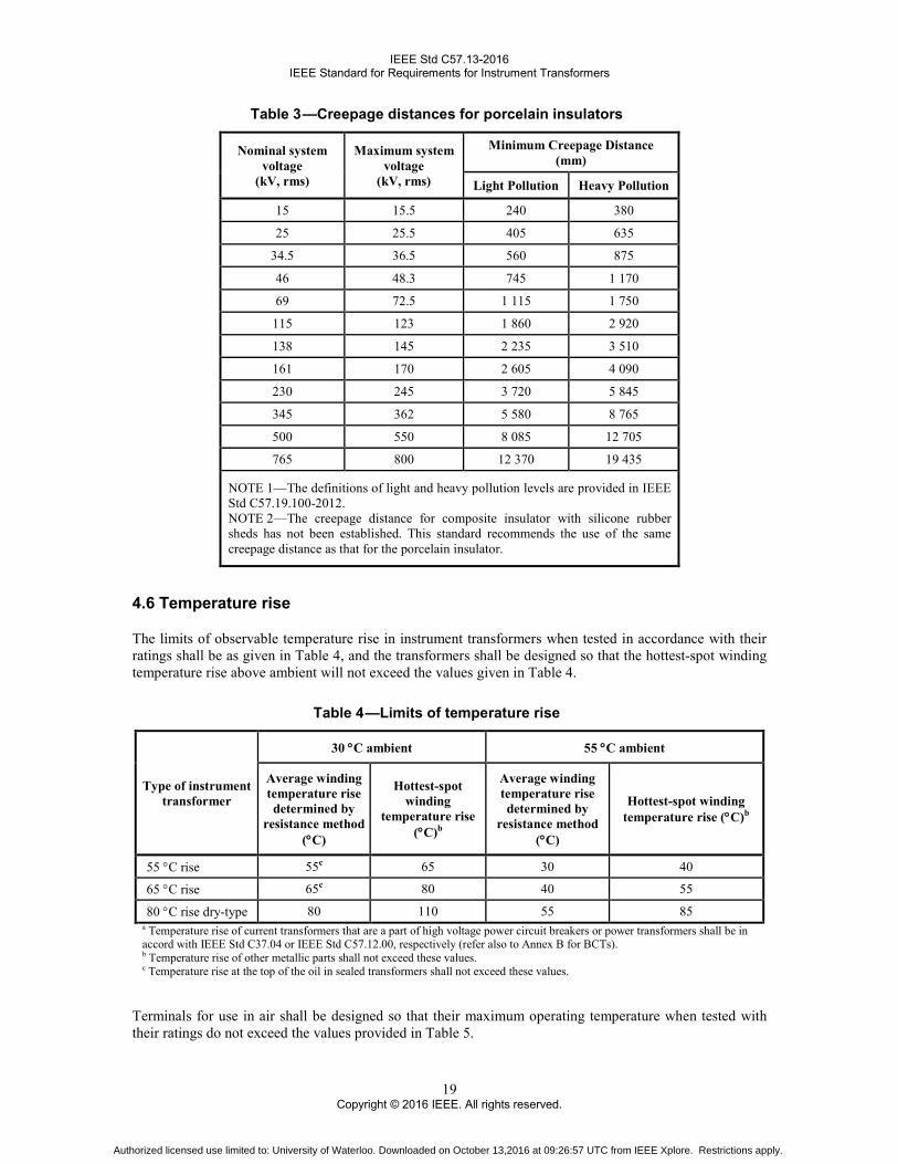
Table 3 —Creepage distances for porcelain insulators
Nominal system voltage
(kV, rms)
Maximum system voltage
(kV, rms)
Minimum Creepage Distance (mm)
Light Pollution Heavy Pollution
15 15.5 240 380
25 25.5 405 635
34.5 36.5 560 875
46 48.3 745 1 170
69 72.5 1 115 1 750
115 123 1 860 2 920
138 145 2 235 3 510
161 170 2 605 4 090
230 245 3 720 5 845
345 362 5 580 8 765
500 550 8 085 12 705
765 800 12 370 19 435
NOTE 1— The definitions of light and heavy pollution levels are provided in IEEE Std C57.19.100-2012. NOTE 2— The creepage distance for composite insulator with silicone rubber sheds has not been established. This standard recommends the use of the same creepage distance as that for the porcelain insulator.
4.6 Temperature rise
The limits of observable temperature rise in instrument transformers when tested in accordance with their ratings shall be as given in Table 4, and the transformers shall be designed so that the hottest-spot winding temperature rise above ambient will not exceed the values given in Table 4.
Table 4 —Limits of temperature rise
Type of instrument transformer
30 °C ambient 55 °C ambient
Average winding temperature rise determined by
resistance method (°C)
Hottest-spot winding
temperature rise (°C)b
Average winding temperature rise determined by
resistance method (°C)
Hottest-spot winding temperature rise (°C)b
55 °C rise 55c 65 30 40
65 °C rise 65c 80 40 55
80 °C rise dry-type 80 110 55 85 a Temperature rise of current transformers that are a part of high voltage power circuit breakers or power transformers shall be in accord with IEEE Std C37.04 or IEEE Std C57.12.00, respectively (refer also to Annex B for BCTs). b Temperature rise of other metallic parts shall not exceed these values. c Temperature rise at the top of the oil in sealed transformers shall not exceed these values.
Terminals for use in air shall be designed so that their maximum operating temperature when tested with their ratings do not exceed the values provided in Table 5.
Authorized licensed use limited to: University of Waterloo. Downloaded on October 13,2016 at 09:26:57 UTC from IEEE Xplore. Restrictions apply.

IEEE Std C57.13-2016 IEEE Standard for Requirements for Instrument Transformers
20 Copyright © 2016 IEEE. All rights reserved.
Table 5 —Maximum operating temperature of power terminals intended for bolted connection in air
Performance Bare copper or
aluminum terminals (°C)
Tin-plated terminals
(°C)
Silver-plated terminals
(°C)
Maximum operating temperature 90 105 115
Maximum operating temperature for use in metal enclosed switchgear a
70 105 105
a Refer to IEEE Std C37.20.1, IEEE Std C37.20.2 and IEEE Std C37.20.3.
4.7 Capacitance and dissipation factor requirements
The capacitance and dissipation factor of the transformer shall be measured at power frequency at the following test voltages:
10 kV
Maximum rated voltage
The test shall be performed before and after the dielectric tests. The increase of capacitance measured after compared with that measured before the dielectric tests shall be less than the value produced by the breakdown of one capacitive element.
The dissipation factor shall be in accordance with the following requirements:
a) For oil-filled transformers
1) The dissipation factor shall be 0.5% maximum at a reference ambient temperature of 20°C.
2) The absolute increase of the dissipation factor value measured after compared with the value measured before the dielectric tests shall be less than 0.1%.
b) For gas-filled transformers
1) The dissipation factor shall be 0.15% maximum at a reference ambient temperature of 20°C.
2) The absolute increase of the dissipation factor value measured after compared with the value measured before the dielectric tests shall be less than 0.03%.
c) For transformers with a rated voltage less than 10 kV, for dry type molded transformers without capacitive graded insulation or for bushing current transformers these capacitance and dissipation factor requirements do not apply.
4.8 Classification of tests
These are the routine, type, and other tests that are necessary to assure that the design and construction of the transformer are adequate to meet the specified requirements. The method of making tests shall be as described in Clause 8 through Clause 13, or by equivalent alternative methods. Many references are available as sources for the material in the preceding clauses. Those references referred to specifically are listed by number in Annex A. Other references, which may be of general utility to the user of these clauses, or of the complete standard, are also included in Annex A. Routine and type tests are in Table 6.
Authorized licensed use limited to: University of Waterloo. Downloaded on October 13,2016 at 09:26:57 UTC from IEEE Xplore. Restrictions apply.
IEEE Std C57.13-2016 IEEE Standard for Requirements for Instrument Transformers
21 Copyright © 2016 IEEE. All rights reserved.
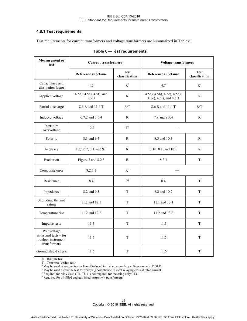
4.8.1 Test requirements
Test requirements for current transformers and voltage transformers are summarized in Table 6.
Table 6 —Test requirements
Measurement or test Current transformers Voltage transformers
Reference subclause Test classification Reference subclause Test
classification
Capacitance and dissipation factor 4.7 Rd 4.7 Rd
Applied voltage 4.5d), 4.5e), 4.5f), and 8.5.3 R 4.5a), 4.5b), 4.5c), 4.5d),
4.5e), 4.5f), and 8.5.3 R
Partial discharge 8.6 R and 11.4 T R/T 8.6 R and 11.4 T R/T
Induced voltage 6.7.2 and 8.5.4 R 7.9 and 8.5.4 R
Inter-turn overvoltage 12.3 Ta —
Polarity 8.3 and 9.4 R 8.3 and 10.3 R
Accuracy Figure 7, 8.1, and 9.1 R 7.10, 8.1, and 10.1 R
Excitation Figure 7 and 8.2.3 R 8.2.3 T
Composite error 8.2.3.1 Rb —
Resistance 8.4 Rc 8.4 T
Impedance 8.2 and 9.3 T 8.2 and 10.2 T
Short-time thermal rating 11.1 and 12.1 T 11.1 and 13.1 T
Temperature rise 11.2 and 12.2 T 11.2 and 13.2 T
Impulse tests 11.3 T 11.3 T
Wet voltage withstand tests – for outdoor instrument
transformers
11.5 T 11.5 T
Ground shield check 11.6 T 11.6 T
R – Routine test T – Type test (design test) a May be used as routine test in lieu of induced test when secondary voltage exceeds 1200 V. b May be used as routine test for verifying compliance to meet relaying class at rated current. c Required for relay class CTs. This is not required for metering only CTs. d Required for oil-filled and gas-filled instrument transformers.
Authorized licensed use limited to: University of Waterloo. Downloaded on October 13,2016 at 09:26:57 UTC from IEEE Xplore. Restrictions apply.

IEEE Std C57.13-2016 IEEE Standard for Requirements for Instrument Transformers
22 Copyright © 2016 IEEE. All rights reserved.
4.8.2 Special tests for gas-filled instrument transformers
These tests are to be performed subject to agreement between the producer and the user. Procedures for the following tests can be found in IEEE Std C57.13.5:
a) Sealing system test
b) Internal arc test
4.8.3 Other tests
Other tests are additional tests made for application information, for provision of specific data requested by users, for verification of type capability, and so on. Examples of other tests are, but not limited to the following:
a) Special accuracy tests
b) Voltage transformer capabilities in respect to 125%, 140%, and 173% overvoltage characteristics
c) Radio influence voltage test (RIV)
d) Thermal-cycle tests
e) Seismic evaluations/tests
f) Mechanical loading
4.9 Construction
4.9.1 Polarity and terminal marking
The relative instantaneous polarity of terminals or leads shall be clearly indicated by permanent markings that cannot easily be obliterated.
When the polarity is indicated by letters, the letter “H” shall be used to distinguish the leads or terminals connected to the primary winding and the letter “X” (also “Y” and “Z,” etc., if multiple secondary windings are provided) shall be used to distinguish the leads or terminals connected to the secondary winding. In addition, each lead shall be numbered, for example, H1, H2, X1, and X2. If more than three secondary windings are provided, they shall be identified as X, Y, Z, and W for four secondary windings; X, Y, Z, W, and V for five secondary windings; X, Y, Z, W, V, and U for six secondary windings, and so on. H1 and X1 (also Y1 and Z1, etc., if provided) shall be of the same polarity.
When multiple primary windings are provided, the leads or terminals shall be designated by the letter “H” together with consecutive pairs of numbers (H1, H2, H3, H4, etc.). The odd-numbered leads or terminals shall be of the same polarity.
When taps or leads are provided on the secondary winding(s), the leads or terminals shall be lettered as required above and numbered X1, X2, X3, etc., or Y1, Y2, Y3, etc., with the lowest and highest numbers indicating the full winding and the intermediate numbers indicating the taps in their relative order. When X1 is not in use, the lower number of the two leads in use shall be the polarity lead. In the case of dual primary ratios that are obtained by secondary taps, the X3 or Y3 terminal shall be common to both taps.
Authorized licensed use limited to: University of Waterloo. Downloaded on October 13,2016 at 09:26:57 UTC from IEEE Xplore. Restrictions apply.
IEEE Std C57.13-2016 IEEE Standard for Requirements for Instrument Transformers
23 Copyright © 2016 IEEE. All rights reserved.
4.9.2 Ground shield requirements
For 72 kV class instrument transformers and above a ground shield shall be provided between the primary and secondary windings.
4.9.3 Symbols
Instrument transformer symbols are given in Table 7.
Authorized licensed use limited to: University of Waterloo. Downloaded on October 13,2016 at 09:26:57 UTC from IEEE Xplore. Restrictions apply.

IEEE Std C57.13-2016 IEEE Standard for Requirements for Instrument Transformers
24 Copyright © 2016 IEEE. All rights reserved.
Table 7 —Instrument transformer symbols Symbol Voltage transformers Current transformers : (colon)
Ratio expression, only to show ratio between primary and secondary voltages or between primary and
tertiary voltages
Example: Voltage transformer with one primary winding and one
secondary winding 14 400:120 V Ratio 120:1
Ratio between primary and secondary amperes
Example: Current transformer with one primary winding and one secondary winding
Current ratio 100:5 A
× (multiplication sign)
Voltage ratings or ratios of transformer with a primary or
secondary winding having two or more coils for series or parallel
connection
Example: Voltage transformer with primary winding in two coils for
series or parallel connection for two ratings.
2 400 × 4 800 V Ratio 20 × 40:1
Current ratings of transformer with a primary or secondary winding having two or more coils for series
or parallel connection
Example: Current transformer with two primary windings in two coils for series or parallel connection
for two ratios Current ratio
100 × 200:5 A
& (ampersand)
Voltage ratings or ratios of separate secondary windings on one core
Example: Voltage transformer for connection line-to-ground, with one primary winding and two secondary
windings 14 400:120 & 72 V Ratio 120:1 & 200:1
Ampere ratings of separate primary windings on one core (When all primary current ratings are the same, the transformer shall produce rated secondary current when
each primary winding carries rated current and the primary currents are in phase. When all primary currents
are not the same, the transformer shall produce rated secondary current when the primary current is rated
current in only one primary winding.)
a) Transformer with two or more primary windings designed to be used individually
Example: Current transformer with two primary windings
Current ratio 100 & 600:5 A
b) Totalizing transformer with two or more primary windings that can be used simultaneously and connected
in different circuits
Example: Totalizing current transformer with three primary windings
Current ratio 5 & 5 & 5:5 A
c) Transformer for three-wire single-phase circuit with two separate primary windings
Example: Current transformer for three-wire single-phase
Current ratio 100 & 100:5 A
Authorized licensed use limited to: University of Waterloo. Downloaded on October 13,2016 at 09:26:57 UTC from IEEE Xplore. Restrictions apply.

IEEE Std C57.13-2016 IEEE Standard for Requirements for Instrument Transformers
25 Copyright © 2016 IEEE. All rights reserved.
Table 7—Instrument transformer symbols (continued)
Symbol Voltage transformers Current transformers / (single slant line)
Two or more primary or secondary voltage ratings obtained by taps in the
secondary winding.
Example: Voltage transformer with taps in the secondary winding for additional primary voltage ratings
8 400/12 000/14 400 V Ratio 70/100/120:1
Example: Voltage transformer with a tap in the secondary winding for
additional secondary voltage ratings 14 000 V
Ratio 120/200:1
Different primary current ratings obtained by taps in the secondary winding
Example: Current transformer with taps in the secondary winding for additional ratios
Current ratio 300/400/600:5 A
// (double slant line)
(Not used) Ampere ratings of separate secondary windings each having an independent core
Example: Current transformer with two separate secondary windings and two cores
Current Ratio 600:5//5
E / (E/E1Y) / (E/E,GrdY) (Designation of primary voltage ratings)
Example: Voltage transformer with E-rated voltage for connection on an E
voltage system 14 000
(E)
Example: Voltage transformer with E-rated voltage that is suitable for
connection on an E voltage system or for Y connection on an E1 voltage
system 2 400/4 160Y
(E/E1Y)
Example: Voltage transformer with E-rated voltage with reduced insulation
at neutral end, for line-to-ground connection on an E1 voltage system
7 200/12 470GrdY (E/E, GrdY)
(Not used directly)
5. Accuracy classes for metering
5.1 Basis for accuracy classes
Accuracy classes for revenue metering are based on the requirement that the transformer correction factor (TCF) of the voltage transformer or of the current transformer shall be within the specified limits when the power factor (lagging) of the metered load has any value from 0.6 to 1.0, under specified conditions as follows:
a) For current transformers, at the specified standard burden (see 6.2 for standard burdens) at 10% or 5% (see Table 10), and at 100% of rated primary current [also at the current corresponding to the
Authorized licensed use limited to: University of Waterloo. Downloaded on October 13,2016 at 09:26:57 UTC from IEEE Xplore. Restrictions apply.

IEEE Std C57.13-2016 IEEE Standard for Requirements for Instrument Transformers
26 Copyright © 2016 IEEE. All rights reserved.
rating factor (RF) if it is greater than 1.0]. The accuracy class at a lower standard burden is not necessarily the same as at the specified standard burden.
b) For voltage transformers, for any burden in voltamperes from zero to the specified standard burden, at the specified standard burden power factor (see 7.2 for standard burdens), and at any voltage from 90% to 110% of the rated voltage. The accuracy class at a lower standard burden of a different power factor is not necessarily the same as at the specified standard burden.
5.2 Expression of transformer correction factor at 0.6 power factor (lagging) of metered load
It can be shown that a TCF at 0.6 power factor (lagging) of the metered load is as follows8:
a) For voltage transformers
TCF RCF2600γ
= + (1)
b) For current transformers
TCF = RCF2600β
− (2)
where
RCF is the ratio correction factor derived from 1 – (±Ratio Error/100). Note that for transformers having negative ratio error the RCF will be greater than unity.
γ, ß is the phase angle, in minutes, for voltage transformers and current transformers, respectively.
5.3 Standard accuracy classes
The limits of transformer correction factor in standard accuracy classes shall be as shown in Table 8.
8 This is true of errors within the range of the standard metering accuracy classes.
Authorized licensed use limited to: University of Waterloo. Downloaded on October 13,2016 at 09:26:57 UTC from IEEE Xplore. Restrictions apply.

IEEE Std C57.13-2016 IEEE Standard for Requirements for Instrument Transformers
27 Copyright © 2016 IEEE. All rights reserved.
Table 8 —Standard accuracy class for metering service and corresponding limits of transformer correction factor and ratio correction factor [0.6 to 1.0 power factor (lagging)
of metered load]c
Metering accuracy class
Voltage transformers (at 90% to 110% rated
voltage) Current transformers
Minimum Maximum At 100% rated currenta At 10% rated current At 5% rated current
Minimum Maximum Minimum Maximum Minimum Maximum
0.15Sb — — 0.9985 1.0015 — — 0.9985 1.0015
0.15b 0.9985 1.0015 0.9985 1.0015 — — 0.9970 1.0030
0.15N — — 0.9985 1.0015 0.9970 1.0030 — —
0.3S — — 0.9970 1.0030 — — 0.9970 1.0030
0.3 0.9970 1.0030 0.9970 1.0030 0.9940 1.0060 — —
0.6 0.9940 1.0060 0.9940 1.0060 0.9880 1.0120 — —
1.2 0.9880 1.0120 0.9880 1.0120 0.9760 1.0240 — — a For current transformers, the 100% rated current limit also applies to the current corresponding to the continuous thermal current rating factor. b Previously defined in IEEE Std C57.13.6. c Other accuracy requirements may be specified and should be included on the nameplate.
5.4 Limiting values of ratio correction factor and phase angle for standard accuracy classes
The limiting values of RCF are the same as those for TCF (see 5.2). For any known value of RCF for a given transformer the limiting values of the angles derived from the expression in 5.2 are given as shown in Equation (3) and Equation (4).9
a) For voltage transformers
2600 (TCF RCF)γ = × − (3)
b) For current transformers
2600 (RCF TCF)β = × − (4)
in which TCF is taken as the maximum and minimum values, given in Table 8, for the specified accuracy class.
These relations are shown graphically in Figure 2, Figure 3, and Figure 4 for current transformers, and Figure 5 for voltage transformers.
9 This is true of errors within the range of the standard metering accuracy classes.
Authorized licensed use limited to: University of Waterloo. Downloaded on October 13,2016 at 09:26:57 UTC from IEEE Xplore. Restrictions apply.

IEEE Std C57.13-2016 IEEE Standard for Requirements for Instrument Transformers
28 Copyright © 2016 IEEE. All rights reserved.
Figure 2 —Limits for accuracy classes for current transformers for metering
In Figure 2, the accuracy requirements for 100% rated current also apply at the continuous thermal current rating of the transformer.
Figure 3 —Limits for 0.15 accuracy class for current transformers for metering
In Figure 3, the transformer characteristics shall lie within the stated limits of the parallelogram at 5% and 100% of rated current. For current transformers, the 100% rated current limits also applies to the current corresponding to the continuous thermal current rating factor, if it is greater than 1.0.
Authorized licensed use limited to: University of Waterloo. Downloaded on October 13,2016 at 09:26:57 UTC from IEEE Xplore. Restrictions apply.
IEEE Std C57.13-2016 IEEE Standard for Requirements for Instrument Transformers
29 Copyright © 2016 IEEE. All rights reserved.
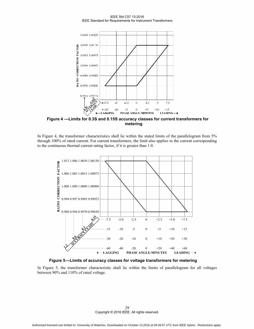
Figure 4 —Limits for 0.3S and 0.15S accuracy classes for current transformers for
metering
In Figure 4, the transformer characteristics shall lie within the stated limits of the parallelogram from 5% through 100% of rated current. For current transformers, the limit also applies to the current corresponding to the continuous thermal current rating factor, if it is greater than 1.0.
ACCURACY CLASS
0.15
0.3
0.6
1.2
0.988 0.994 0.9970 0.99850
0.994 0.997 0.9985 0.99925
1.000 1.000 1.0000 1.00000
1.006 1.003 1.0015 1.00075
1.012 1.006 1.0030 1.00150
LEADINGLAGGING PHASE ANGLE-MINUTES
RA
TIO
CO
RR
EC
TIO
N F
AC
TO
R
-7.5 -5.0 -2.5 0 +2.5 +5.0 +7.5
-15 -10 -5 0 +5 +10 +15
-30 -20 -10 0 +10 +20 +30
-60 -40 -20 0 +20 +40 +60
Figure 5 —Limits of accuracy classes for voltage transformers for metering
In Figure 5, the transformer characteristic shall lie within the limits of parallelogram for all voltages between 90% and 110% of rated voltage.
Authorized licensed use limited to: University of Waterloo. Downloaded on October 13,2016 at 09:26:57 UTC from IEEE Xplore. Restrictions apply.

IEEE Std C57.13-2016 IEEE Standard for Requirements for Instrument Transformers
30 Copyright © 2016 IEEE. All rights reserved.
6. Current transformers
6.1 Terms in which ratings shall be expressed
The ratings of a current transformer shall include:
a) Basic impulse insulation level in terms of full-wave test voltage (see Table 2).
b) Nominal system voltage or maximum system voltage (see Table 2).
c) Frequency (in Hz).
d) Rated primary and secondary currents (see 6.3, as well as Table 9 and Table 2).
e) Accuracy classes at standard burdens (see 6.3, 6.4, as well as, Table 8, Table 10, and Table 13).
f) Continuous thermal current rating factor based on 30 °C average ambient air temperature, unless otherwise stated (see 6.5).
g) Short-time mechanical current rating and short-time thermal current rating (see 6.6).
Table 9 —Example of ratings for current transformers with one or two ratios
Typical Current ratings (A)a
Single ratio Double ratio with
series-parallel primary windings
Double ratio with taps in secondary
winding
5:5 150:5 1 500:5 25 × 50:5 25/50:5
10:5 200:5 1 600:5 50 × 100:5 50/100:5
15:5 250:5 2 000:5 100 × 200:5 100/200:5
20:5 300:5 2 500:5 200 × 400:5 200/400:5
25:5 400:5 3 000:5 400 × 800:5 300/600:5
30:5 500:5 4 000:5 500 × 1 000:5 400/800:5
40:5 600:5 5 000:5 600 × 1 200:5 500/1 000:5
50:5 750:5 6 000:5 1 000 × 2 000:5 600/1 200:5
60:5 800:5 8 000:5 2 000 × 4 000:5 1 000/2 000:5
75:5 1 000:5 10 000:5
1 500/3 000:5
100:5 1 200:5 12 000:5 2 000/4 000:5 a Other ratings may be selected as agreed upon between manufacturer and end user.
6.2 Standard burdens
Standard burdens for current transformers with 5 A rated secondary current shall have resistance and inductance according to Table 10 for metering and Table 13 for relaying.
6.3 Accuracy ratings for metering
A current transformer for metering shall be given an accuracy rating for each standard burden for which it is rated (see Clause 5). The accuracy class may be stated for the maximum burden for which it is rated and
Authorized licensed use limited to: University of Waterloo. Downloaded on October 13,2016 at 09:26:57 UTC from IEEE Xplore. Restrictions apply.

IEEE Std C57.13-2016 IEEE Standard for Requirements for Instrument Transformers
31 Copyright © 2016 IEEE. All rights reserved.
will imply that all other lower burdens shall also be in that class; e.g., 0.3 B-1.8 would imply 0.3 B-0.1, B-0.2, B-0.5, B-0.9, and B-1.8. If the accuracy class given is specific only to that burden it is assigned, e.g., 0.3 @ B-0.5, or a range of burdens, e.g., 0.3 @ B0.5-B0.9, then the accuracy class is not guaranteed for other burdens unless specifically stated.
Electronic meters and connecting circuits may present a lower burden, thus affecting a current transformers ratio and phase angle. A current transformer that meets a given accuracy class at B-0.1 and less may not meet the same accuracy class when the application calls for burden power factor between 0.9 and unity. “E” burdens shall be stated separately.
Table 10 —Standard metering burdens for current transformers with 5 A secondary windingsa
Burdens Burden designationb
Resistance (Ω)
Inductance (mH)
Impedance (Ω)c
Total Power (VA at 5 A)
Total Power (VA at 1 A)
Power factor
Electronic burdens
E0.04 0.04 0 0.04 1.0 0.04 1.0
E0.2 0.2 0 0.2 5.0 0.2
Metering burdens
B-0.1 0.09 0.116 0.1 2.5 0.1
0.9 B-0.2 0.18 0.232 0.2 5.0 0.2 B-0.5 0.45 0.580 0.5 12.5 0.5 B-0.9 0.81 1.040 0.9 22.5 0.9 B-1.8 1.62 2.080 1.8 45.0 1.8
a If a current transformer secondary winding is rated at other than 5 A, the impedance, the power factor, and the burden designation remain the same while the VA at rated current shall be adjusted by [5/(ampere rating)].2 b These standard burden designations have no significance at frequencies other than 60 Hz. c The impedance tolerance is +5% and –0%.
6.3.1 Tapped-secondary or multiple-ratio current transformer accuracy rating
The metering accuracy rating applies only to the full secondary winding, unless otherwise specified (see Table 11).
Authorized licensed use limited to: University of Waterloo. Downloaded on October 13,2016 at 09:26:57 UTC from IEEE Xplore. Restrictions apply.

IEEE Std C57.13-2016 IEEE Standard for Requirements for Instrument Transformers
32 Copyright © 2016 IEEE. All rights reserved.
Table 11 —Current transformer ratings, multi-ratio type
Current ratings (A)
Secondary taps
Current ratings (A)
Secondary taps
600:5 3000:5 50:5 X2 − X3 300:5 X3 − X4
100:5 X1 − X2 500:5 X4 − X5 150:5 X1 − X3 800:5 X3 − X5 200:5 X4 − X5 1000:5 X1 − X2 250:5 X3 − X4 1200:5 X2 − X3 300:5 X2 − X4 1500:5 X2 − X4 400:5 X1 − X4 2000:5 X2 − X5 450:5 X3 − X5 2200:5 X1 − X3 500:5 X2 − X5 2500:5 X1 − X4 600:5 X1 − X5 3000:5 X1 − X5
1200:5 4000:5 100:5 X2 − X3 500:5 X1 − X2 200:5 X1 − X2 1000:5 X3 − X4 300:5 X1 − X3 1500:5 X2 − X3 400:5 X4 − X5 2000:5 X1 − X3 500:5 X3 − X4 2500:5 X2 − X4 600:5 X2 − X4 3000:5 X1 − X4 800:5 X1 − X4 3500:5 X2 − X5 900:5 X3 − X5 4000:5 X1 − X5
1000:5 X2 − X5
1200:5 X1− X5 2000:5 5000:5
300:5 X3 − X4 500:5 X2 − X3 400:5 X1 − X2 1000:5 X4 − X5 500:5 X4 − X5 1500:5 X1 − X2 800:5 X2 − X3 2000:5 X3 − X4
1100:5 X2 − X4 2500:5 X2 − X4 1200:5 X1 − X3 3000:5 X3 − X5 1500:5 X1 − X4 3500:5 X2 − X5 1600:5 X2 − X5 4000:5 X1 − X4 2000:5 X1 − X5 5000:5 X1 − X5
6.4 Accuracy ratings for relaying
A current transformer designed for relaying purposes shall be given an accuracy rating according to Table 12.
Authorized licensed use limited to: University of Waterloo. Downloaded on October 13,2016 at 09:26:57 UTC from IEEE Xplore. Restrictions apply.

IEEE Std C57.13-2016 IEEE Standard for Requirements for Instrument Transformers
33 Copyright © 2016 IEEE. All rights reserved.
Table 12 —Relaying current transformer accuracy
Relay class Limits of ratio error
@ rated current @ 20 times rated current
C and T classification 3%a 10%
X classification 1% user defined aFor window type CT with 50 secondary turns (250.5) or less, the ratio error at rated current may exceed 3%.
Table 13 —Standard relaying burdens for current transformers with 5 A secondary windings
Burdens Burden designationb
Resistance (Ω)
Inductance (mH)
Impedance (Ω)c
Total Power (VA at 5 A)
Power Factor
Terminal Voltage
Relaying burdens
B-0.1 0.09 0.116 0.1 2.5 0.9 10 B-0.2 0.18 0.232 0.2 5.0 0.9 20
B-0.5 0.45 0.580 0.5 12.5 0.9 50
B-1.0 0.50 2.300 1.0 25.0 0.5 100
B-2.0 1.00 4.600 2.0 50.0 0.5 200
B-4.0 2.00 9.200 4.0 100.0 0.5 400
B-8.0 4.00 18.400 8.0 200.0 0.5 800 a If a current transformer secondary winding is rated at other than 5 A, the equivalent burden shall be derived by dividing the secondary terminal voltage by (IS × 20). For example, if the rated secondary current is 1 A and the relay class is C100, then the corresponding burden to develop the secondary terminal voltage would be 100 V / (1 A × 20) = 5 Ω. b These standard burden designations have no significance at frequencies other than 60 Hz. c The impedance tolerance is +5% and –0%.
6.4.1 Basis for relaying accuracy ratings
6.4.1.1 C classification
Covers current transformers in which the leakage flux in the core of the transformer does not have an appreciable effect on the ratio(s) within the limits defined in 6.4 with standard burdens outlined in Table 13, so that the ratio can be calculated in accordance with 9.1.1, 9.1.2, and 9.1.3.
6.4.1.2 T classification
Covers current transformers in which the leakage flux does have an appreciable effect on the ratio(s) within the limits defined in Table 13 with standard burdens outlined in Table 13, such that it is not practical to calculate the ratio.
6.4.1.3 Secondary terminal voltage
The relay classification for C and T class is given in terms of the secondary terminal voltage, which the current transformer will deliver to a standard burden at 20 times rated current without exceeding the limits outlined in 6.4. The secondary terminal voltage ratings are based on 5 A nominal secondary current (100 A at 20 times) and standard burdens as per Table 13.
Authorized licensed use limited to: University of Waterloo. Downloaded on October 13,2016 at 09:26:57 UTC from IEEE Xplore. Restrictions apply.

IEEE Std C57.13-2016 IEEE Standard for Requirements for Instrument Transformers
34 Copyright © 2016 IEEE. All rights reserved.
6.4.1.4 X classification
User defined for a specific condition in which the minimum secondary excitation requirements are given as follows:
Ek is the the minimum knee-point voltage Ik is the the maximum exciting current at Ek Rct is the maximum allowable secondary winding direct current measured resistance corrected to
75 °C
The ratio error at rated current shall be as defined in 6.4. If only Ek is given, then the manufacturer will establish Ik and Rct based on the necessary design required to meet Ek.
6.4.1.5 Transient performance classifications
For requirements for Class TPX, TPY, and TPZ current transformers, refer to IEC 61869-2.
6.4.2 Tapped secondary or multi ratio current transformer
The relay accuracy class applies only to the full winding, unless otherwise specified. If transformers have C classification on the full winding, all tapped sections shall be arranged so that the ratio can be calculated in accordance with 9.1.1, 9.1.2, and 9.1.3.
6.5 Continuous thermal current rating factors based on 30 °C average ambient air temperature
The preferred continuous thermal current rating factors are 1.0, 1.33, 1.5, 2.0, 3.0, or 4.0.
6.6 Short-time current ratings
The short-time thermal current and short-time mechanical capabilities are not independent.
6.6.1 Short-time mechanical current rating
The short-time mechanical current rating is the maximum peak value of a fully displaced (asymmetrical) primary current wave whose magnitude shall be 2.7 times the short-time thermal rating, that the transformer is capable of withstanding with the secondary winding short-circuited. “Capable of withstanding” shall be interpreted to mean that if subjected to this duty, the current transformer shall show no damage and shall be capable of meeting the other applicable requirements of this standard.
6.6.2 Short-time thermal current rating
The short-time thermal current rating of a current transformer is the rms symmetrical primary current that can be carried for 1 s with the secondary winding short-circuited without exceeding in any winding the limiting temperature. The temperature of a conductor in the windings of a current transformer shall be determined from calculation using methods specified in 11.1.2.
Authorized licensed use limited to: University of Waterloo. Downloaded on October 13,2016 at 09:26:57 UTC from IEEE Xplore. Restrictions apply.

IEEE Std C57.13-2016 IEEE Standard for Requirements for Instrument Transformers
35 Copyright © 2016 IEEE. All rights reserved.
The limiting temperature shall be 250 °C for copper conductor or 200 °C for electrical conductor (EC) aluminum. A maximum temperature of 250 °C shall be allowed for aluminum alloys that have resistance to annealing properties at 250 °C equivalent to EC aluminum at 200 °C, or for applications of EC aluminum where the characteristics of the fully annealed material satisfy the mechanical requirements.
If the 1 second rating is not dependent on core saturation (see 12.1), the short-time thermal current rating for any time up to 5 s may be determined from the 1 s rating by dividing the current for 1 s by the square root of the specified number of seconds. For example, the 3 second thermal current rating is equal to the 1 second current rating divided by the square root of 3, or 58% of the one-second rating. This calculation includes the assumption that the primary current is symmetrical during the time interval.
6.6.3 Short-time and continuous current ratings of window-type or bushing-type current transformers
Such current transformers, in which the primary conductor is not an integral part of the current transformers, shall be rated in terms of primary current, even though the short-time mechanical and thermal limitations and the continuous thermal limitations are those of the secondary winding only. Such ratings specified for current transformers of this construction should not be considered to be applicable to the conductor used for the primary winding of these transformers; as such, the conductor may be a component of other apparatus or bus work having different limitations. For bushing-type current transformers, see Annex B.
6.7 Secondary winding-induced voltages
6.7.1 Operation with secondary circuit open
Current transformers should never be operated with the secondary circuit open because hazardous peak voltages may result. Transformers conforming to this standard shall be capable of operating under emergency conditions for 1 minute with rated primary current times the rating factor with the secondary circuit open if the open-circuit voltage does not exceed 3500 V peak.
When the open circuit voltage exceeds 3500 V peak, the user should consider applying a voltage limiting device (varistors or spark gaps) across the secondary terminals. The voltage limiting device should be able to withstand an open-circuit situation for a period of 1 minute without damage to the secondary circuit. The voltage limiting device may need to be replaced after such an abnormal condition.
6.7.2 Induced voltage test
For test frequencies of 120 Hz and below the 1 minute test voltage applied to the secondary terminals with the primary winding open shall be twice the relay rated secondary terminal voltage given in 6.4.1.3 but not less than 200 V. For test frequencies above 120 Hz, see 8.5.4 for test duration. Transformers with no relay voltage classification shall be tested at 200 V.
For X classification the induced level shall be 2 × Ek or 2500 V rms (3.5 kV peak), whichever is less.
If a frequency higher than 60 Hz is necessary to avoid excessive exciting current, see 8.5.4 for reduced time of application. If the voltage cannot be induced sinusoidally even at 400 Hz without core saturation, no test is required.
Authorized licensed use limited to: University of Waterloo. Downloaded on October 13,2016 at 09:26:57 UTC from IEEE Xplore. Restrictions apply.
IEEE Std C57.13-2016 IEEE Standard for Requirements for Instrument Transformers
36 Copyright © 2016 IEEE. All rights reserved.
This test is not required for window-type or bar-type 10 kV BIL current transformers that are rated below 600 A and that have no relay accuracy rating.
6.8 Nameplates
Current transformers shall be provided with nameplates that shall include, as a minimum, the following information (see Table 7):
a) Manufacturer’s name or trademark
b) Manufacturer’s type
c) Manufacturer’s serial number
d) Year of manufacture
e) Rated primary current
f) Rated secondary current
g) Nominal system voltage (NSV) and/or maximum system voltage (MSV) (none for bushing CTs)
h) Basic impulse insulation level (BIL) (none for bushing CTs)
i) Rated frequency (Hz)
j) Short-time thermal and mechanical rating
k) Continuous thermal current rating factor (RF) (State ambient if other than 30 °C)
l) Accuracy rating
1) Metering accuracy class at specified standard burdens
2) Relaying accuracy rating on transformers intended primarily for relaying applications
m) Applicable standard (IEEE Std C57.13 for Class 1 and IEEE Std C57.13.5 for Class 2)
n) For oil-filled transformers the nameplate shall indicate that the transformer contains no detectable levels of PCB at the time of manufacture.
NOTE 1— See IEEE Std C37.04 and NEMA SG 4 for nameplate requirements in high-voltage circuit breakers.
NOTE 2— Additional requirements for BCTs, refer to Annex B.
6.9 Terminals
The primary terminals of wound-type and bar-type current transformers shall be suitable for use with either aluminum or copper conductors. The secondary terminals and voltage terminals, where provided, shall be suitable for use with copper conductors.
6.10 Application data
The characteristic data in 6.10.1 and 6.10.2 suitable for portraying or calculating performance shall be made available upon request.
Authorized licensed use limited to: University of Waterloo. Downloaded on October 13,2016 at 09:26:57 UTC from IEEE Xplore. Restrictions apply.
IEEE Std C57.13-2016 IEEE Standard for Requirements for Instrument Transformers
37 Copyright © 2016 IEEE. All rights reserved.
6.10.1 Data for metering applications
These data shall consist of the following:
a) Typical ratio correction factor and phase angle curves, for the standard burdens for which metering accuracy ratings are assigned, plotted over the range of current per Table 8 from 0.1 or 0.05 times rated current to the maximum continuous thermal current rating. These curves shall be plotted on rectangular coordinate paper and need not be drawn where the errors exceed the limits of the 1.2 accuracy class.
b) Short-time mechanical and short-time thermal current ratings, as defined in 6.6.1 and 6.6.2, respectively.
6.10.2 Data for relaying applications
These data shall consist of the following:
a) Relaying accuracy rating, as defined in 6.4.
b) Short-time mechanical and short-time thermal current ratings, as defined in 6.6.1 and 6.6.2, respectively.
c) Resistance of the secondary winding between the secondary terminals at a specified temperature given in such a way that the value for each published ratio may be determined.
d) For C class transformers, typical excitation curves on log-log coordinate paper, with square decades, plotted between excitation current and induced secondary voltage for each published ratio, extending from 1% of the relay accuracy rating secondary terminal voltage to a voltage that will cause an excitation current of five times rated secondary current.
Curves shall also show the knee of the curve. For current transformers with nongapped cores, the knee is defined as the point where the tangent is at 45° to the abscissa. For current transformers conforming to this standard, it shall be possible to draw the above tangents to the excitation curves. The maximum tolerance of excitation values above and below the knee shall be as shown (see Figure 6).
NOTE—The 45° tangent was established from experience using conventional magnetic materials. The significance of these tangent points will be dependent on the magnetic material in use.
e) For T class transformers, typical overcurrent ratio curves on rectangular coordinate paper plotted between primary and secondary current over the range from 1 to 22 times rated primary current for all the standard burdens10 up to the standard burden, which causes a ratio correction of 50% (see Figure 7).
10 Except B-0.9 and B-1.8.
Authorized licensed use limited to: University of Waterloo. Downloaded on October 13,2016 at 09:26:57 UTC from IEEE Xplore. Restrictions apply.

IEEE Std C57.13-2016 IEEE Standard for Requirements for Instrument Transformers
38 Copyright © 2016 IEEE. All rights reserved.
Figure 6 —Typical excitation curves for multiratio C class current transformers
with nongapped cores
Ek
Authorized licensed use limited to: University of Waterloo. Downloaded on October 13,2016 at 09:26:57 UTC from IEEE Xplore. Restrictions apply.

IEEE Std C57.13-2016 IEEE Standard for Requirements for Instrument Transformers
39 Copyright © 2016 IEEE. All rights reserved.
Figure 7 —Typical overcurrent ratio curve
6.11 Routine accuracy tests
Tests for current transformers with metering accuracy ratings shall be made on each transformer, and they shall consist of the measurement of ratio error (ratio correction factor) and phase angle at rating factor, 100% and at 10% or 5% of rated current as per Table 8, when energized at rated frequency and rated burden. Unless otherwise requested by the customer, non-compensated current transformers shall be tested at only the maximum rated burden.
Routine accuracy tests for current transformers with a relay accuracy rating shall be made on each transformer and shall consist of a turns ratio check, secondary excitation, and RCF measurements at 100% rated current with standard rated burden. For ring-type cores of low reactance, the RCF measurement may be the composite error performed by secondary excitation at the voltage equivalent to standard rated burden at 100% as calculated in 9.1.1, 9.1.2, and 9.1.3.
The routine secondary excitation test shall consist of a knee point determination for C class transformers to prove compliance with the published characteristic curve.
For X classification transformers, the routine secondary excitation test shall consist of measurements of exciting voltage versus exciting current at Ek, and at two additional points (one point above Ek and one point below Ek). The test points are arbitrary and selected for convenience to verify conformance, and shall be at least 50% of Ek. If Rct was a given parameter, it shall be measured and corrected to 75 °C.
Authorized licensed use limited to: University of Waterloo. Downloaded on October 13,2016 at 09:26:57 UTC from IEEE Xplore. Restrictions apply.

IEEE Std C57.13-2016 IEEE Standard for Requirements for Instrument Transformers
40 Copyright © 2016 IEEE. All rights reserved.
All excitation measurements shall be compared with the published curve, and shall comply with the limits indicated in Figure 6 (except for X class where Ek and Ik are maximum limits). Additional points may be required as deemed necessary to prove compliance.
7. Voltage transformers
7.1 Terms in which ratings shall be expressed
The ratings of a voltage transformer shall include:
a) Basic impulse insulation level in terms of full-wave test voltage (see Table 14 through Table 18, as well as Figure 8 through Figure 15).
b) Rated primary voltage and ratio (see Table 14 through Table 18, as well as Figure 8 through Figure 15). Secondary voltage is 120 V up to 25 kV class inclusive and 115 volts above 25 kV.
c) Frequency (in Hz)
d) Accuracy ratings (see 5.3)
e) Thermal burden rating (see 7.4)
In Table 14 through Table 17, voltage transformers connected line-to-ground on an ungrounded system cannot be considered grounding transformers and shall not be operated with the secondary windings in closed delta because excessive currents may flow in the delta.
Table 14 —Ratings and characteristics of group 1 voltage transformers
Rated voltage (V) Marked ratio Basic impulse insulation level (kV peak)
120/208Y 1:1 10 240/416Y 2:1 10 300/520Y 2.5:1 10 120/208Y 1:1 30 240/416Y 2:1 30 300/520Y 2.5:1 30 480/832Y 4:1 30
600/1 040Y 5:1 30 2 400/4 160Y 20:1 60 4 200/7 270Y 35:1 75 4 800/8 320Y 40:1 75
7 200/12 470Y 60:1 110 or 95 8 400/14 400Y 70:1 110 or 95
12 000/20 750Y 100:1 150 or 125 14 400/24 940Y 120:1 150 or 125
a Group 1 voltage transformers are for application with 100% of rated primary voltage across the primary winding when connected line-to-line or line-to-ground. (For typical connections, see Figure 8 and Figure 9.) Group 1 voltage transformers shall be capable of operations at 125% of rated voltage on an emergency (8 h) basis (this capability does not preclude the possibility of ferroresonance), provided the burden, in volt-amperes at rated voltage, does not exceed 64% of the thermal burden rating, without exceeding the following average winding temperatures: 105 °C for 55 °C rise types, 115 °C for 65 °C rise types, and 130 °C for 80 °C rise types. This will result in reduction of life expectancy.
Authorized licensed use limited to: University of Waterloo. Downloaded on October 13,2016 at 09:26:57 UTC from IEEE Xplore. Restrictions apply.
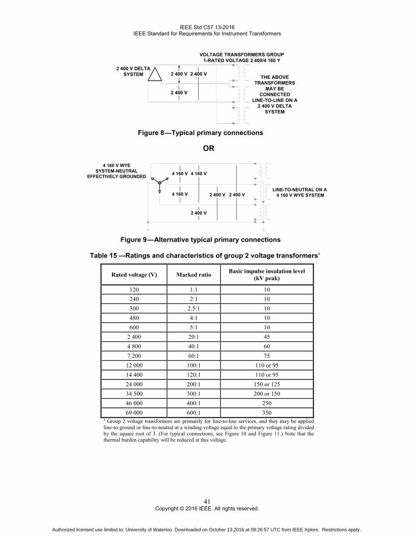
IEEE Std C57.13-2016 IEEE Standard for Requirements for Instrument Transformers
41 Copyright © 2016 IEEE. All rights reserved.
VOLTAGE TRANSFORMERS GROUP 1-RATED VOLTAGE 2 400/4 160 Y
2 400 V DELTA SYSTEM THE ABOVE
TRANSFORMERS MAY BE
CONNECTEDLINE-TO-LINE ON A
2 400 V DELTA SYSTEM
2 400 V
2 400 V
2 400 V
Figure 8 —Typical primary connections
LINE-TO-NEUTRAL ON A 4 160 V WYE SYSTEM4 160 V
4 160 V WYESYSTEM-NEUTRAL
EFFECTIVELY GROUNDED
2 400 V
2 400 V
4 160 V
2 400 V
OR
4 160 V
Figure 9 —Alternative typical primary connections
Table 15 —Ratings and characteristics of group 2 voltage transformersa
Rated voltage (V) Marked ratio Basic impulse insulation level (kV peak)
120 1:1 10 240 2:1 10 300 2.5:1 10 480 4:1 10 600 5:1 10
2 400 20:1 45 4 800 40:1 60 7 200 60:1 75 12 000 100:1 110 or 95 14 400 120:1 110 or 95 24 000 200:1 150 or 125 34 500 300:1 200 or 150 46 000 400:1 250 69 000 600:1 350
a Group 2 voltage transformers are primarily for line-to-line services, and they may be applied line-to-ground or line-to-neutral at a winding voltage equal to the primary voltage rating divided by the square root of 3. (For typical connections, see Figure 10 and Figure 11.) Note that the thermal burden capability will be reduced at this voltage.
Authorized licensed use limited to: University of Waterloo. Downloaded on October 13,2016 at 09:26:57 UTC from IEEE Xplore. Restrictions apply.

IEEE Std C57.13-2016 IEEE Standard for Requirements for Instrument Transformers
42 Copyright © 2016 IEEE. All rights reserved.
VOLTAGE TRANSFORMERS GROUP 2-RATED VOLTAGE 14 400/14 400 Y
14 400 V
14 400 V
14 400 V14 400 V
DELTA SYSTEM THE ABOVE TRANSFORMERS
MAY BE CONNECTED LINE-TO-LINE ON A 14 400 V SYSTEM
BUT ARE LIMITED BY INSULATION
Figure 10 —Typical primary connections
LINE-TO-NEUTRAL CONNECTION ON THE SAME SYSTEM
OR
14 400 V
14 400 V
14 400 V WYE SYSTEM NEUTRAL GROUNDED OR UNGROUNDED
8 314 V
8 314 V
8 314 V14 400 V
Figure 11 —Alternative typical primary connections
Table 16 —Ratings and characteristics of group 3 outdoor voltage transformersa
Rated voltage (V) Marked ratio Basic impulse insulation level (kV peak)
14 400/24 940 Grd Y 120/200 & 120/200:1 150 or 125 20 125/34 500 Grd Y 175/300 & 175/300:1 200 27 600/46 000 Grd Y 240/400 & 240/400:1 250 40 250/69 000 Grd Y 350/600 & 350/600:1 350
69 000/115 000 Grd Y 600/1 000 & 600/1 000:1 550 or 450 80 500/138 000 Grd Y 700/1 200 & 700/1 200:1 650 92 000/161 000 Grd Y 800/1 400 & 800/1 400:1 750
138 000/230 000 Grd Y 1 200/2 000 & 1 200/2 000:1 1050 or 900 207 000/345 000 Grd Y 1 800/3 000 & 1 800/3 000:1 1300 or 1175 287 500/500 000 Grd Y 2 500/4 500 & 2 500/4 500:1 1800 or 1675 431 250/750 000 Grd Y 3 750/6 250 & 3 750/6 250:1 2050
NOTE—The double voltage ratio is usually achieved by a tap in the secondary winding. In such cases, the nonpolarity terminal of the winding shall be the common terminal.
a Group 3 voltage transformers are for line-to-ground connection only and have two secondary windings. They may be insulated-neutral or grounded-neutral terminal type. Ratings through 92 000/161 000 Grd Y shall be capable of the square root of 3 times rated voltage (this capability does not preclude the possibility of ferroresonance) for 1 minute without exceeding a 175 °C temperature rise for copper conductor or a 125 °C rise for EC aluminum. Ratings 138 000/230 000 Grd Y and above shall be capable of operation at 140% of rated voltage with the same limitation of time and temperature. (For typical connections, see Figure 12.) Group 3 transformers shall be capable of continuous operation at 110% of rated voltages, provided the burden in volt-amperes at this voltage does not exceed the thermal burden rating.
Authorized licensed use limited to: University of Waterloo. Downloaded on October 13,2016 at 09:26:57 UTC from IEEE Xplore. Restrictions apply.

IEEE Std C57.13-2016 IEEE Standard for Requirements for Instrument Transformers
43 Copyright © 2016 IEEE. All rights reserved.
39 837 V
VOLTAGE TRANSFORMERSGROUP 3-RATED VOLTAGE
40 250/69 000 GRD Y
ONE PRIMARY TERMINAL OF EACH TRANSFORMER IS NOT FULLY INSULATED AND MUST BE CONNECTED TO GROUND
69 000 V WYE SYSTEM NEUTRAL GROUNDED OR UNGROUNDED
NOMINAL 3-PHASE SYSTEM
39 837 V
39 837 V
69 000 V69 000 V
69 000 V
Figure 12 —Typical primary connections
Table 17 —Ratings and characteristics of group 4 indoor voltage transformersa
Group Rated voltage (V) Marked ratio Basic impulse insulation level (kV peak)
Group 4A: For operations at approximately 100% of rated voltage (see Figure 13)
2 400/4 160 Grd Y 20:1 60 4 200/7 200 Grd Y 35:1 75 4 800/8 320 Grd Y 40:1 75
7 200/12 470 Grd Y 60:1 110 or 95 8 400/14 400 Grd Y 70:1 110 or 95
Group 4B: For operation at approximately 58% of rated voltage (see Figure 14)
4 160/4 160 Grd Y 35:1 60 4 800/4 800 Grd Y 40:1 60 7 200/7 200 Grd Y 60:1 75
12 000/12 000 Grd Y 100:1 110 or 95 14 400/14 400 Grd Y 120:1 110 or 95
a Group 4 voltage transformers are for line-to-ground connection only. They may be insulated-neutral or grounded-neutral terminal type. (For typical connections of Group 4A, see Figure 13. For typical connections of Group 4B, see Figure 14.) Group 4 transformers shall be capable of continuous operation at 110% of rated voltages, provided the burden in volt-amperes at this voltage does not exceed the thermal burden rating. Group 4A voltage transformers shall be capable of operation at 125% of rated voltage on an emergency (8 h) basis (this capability does not preclude the possibility of ferroresonance), provided the burden, in volt-amperes at rated voltage, does not exceed 64% of the thermal burden rating, without exceeding the following average winding temperatures: 105 °C for 55 °C rise types, 115 °C for 65 °C rise types and 130 °C for 80 °C rise types (this will result in a reduction of normal life expectancy).
VOLTAGE TRANSFORMERSGROUP 4A-RATED
VOLTAGE2 400/4 160 GRD Y2 400 V2 400 V
2 400 V
4 160 V
4 160 V
4 160 V4 160 V WYE
SYSTEM-NEUTRALEFFECTIVELYGROUNDED
LINE-TO-GROUNDON A 4 160V WYE
SYSTEM
Figure 13 —Typical primary connections for Group 4A
Authorized licensed use limited to: University of Waterloo. Downloaded on October 13,2016 at 09:26:57 UTC from IEEE Xplore. Restrictions apply.
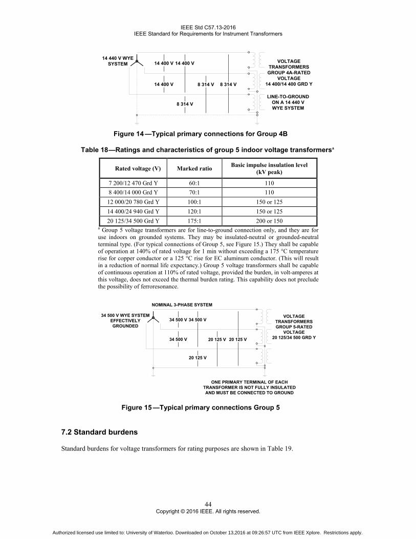
IEEE Std C57.13-2016 IEEE Standard for Requirements for Instrument Transformers
44 Copyright © 2016 IEEE. All rights reserved.
14 440 V WYESYSTEM VOLTAGE
TRANSFORMERSGROUP 4A-RATED
VOLTAGE14 400/14 400 GRD Y
LINE-TO-GROUNDON A 14 440 VWYE SYSTEM
8 314 V
14 400 V14 400 V
14 400 V 8 314 V 8 314 V
Figure 14 —Typical primary connections for Group 4B
Table 18 —Ratings and characteristics of group 5 indoor voltage transformersa
Rated voltage (V) Marked ratio Basic impulse insulation level (kV peak)
7 200/12 470 Grd Y 60:1 110 8 400/14 000 Grd Y 70:1 110
12 000/20 780 Grd Y 100:1 150 or 125 14 400/24 940 Grd Y 120:1 150 or 125 20 125/34 500 Grd Y 175:1 200 or 150
a Group 5 voltage transformers are for line-to-ground connection only, and they are for use indoors on grounded systems. They may be insulated-neutral or grounded-neutral terminal type. (For typical connections of Group 5, see Figure 15.) They shall be capable of operation at 140% of rated voltage for 1 min without exceeding a 175 °C temperature rise for copper conductor or a 125 °C rise for EC aluminum conductor. (This will result in a reduction of normal life expectancy.) Group 5 voltage transformers shall be capable of continuous operation at 110% of rated voltage, provided the burden, in volt-amperes at this voltage, does not exceed the thermal burden rating. This capability does not preclude the possibility of ferroresonance.
34 500 V WYE SYSTEM EFFECTIVELY GROUNDED
VOLTAGE TRANSFORMERSGROUP 5-RATED
VOLTAGE20 125/34 500 GRD Y
ONE PRIMARY TERMINAL OF EACH TRANSFORMER IS NOT FULLY INSULATED AND MUST BE CONNECTED TO GROUND
20 125 V
34 500 V34 500 V
34 500 V 20 125 V 20 125 V
NOMINAL 3-PHASE SYSTEM
Figure 15 —Typical primary connections Group 5
7.2 Standard burdens
Standard burdens for voltage transformers for rating purposes are shown in Table 19.
Authorized licensed use limited to: University of Waterloo. Downloaded on October 13,2016 at 09:26:57 UTC from IEEE Xplore. Restrictions apply.

IEEE Std C57.13-2016 IEEE Standard for Requirements for Instrument Transformers
45 Copyright © 2016 IEEE. All rights reserved.
Table 19 —Standard burdens for voltage transformers
Characteristics on standard burdensa Characteristics on 120 V basisc Characteristics on 69.3 V basisc
Designation VA Power factor
Resistance (Ω)
Inductance (H)
Impedance (Ω)b
Resistance (Ω)
Inductance (H)
Impedance (Ω)b
W 12.5 0.10 115.2 3.0400 1152 38.4 1.0100 384 X 25.0 0.70 403.2 1.0900 576 134.4 0.3640 192 M 35.0 0.20 82.3 1.0700 411 27.4 0.3560 137 Y 75.0 0.85 163.2 0.2680 192 54.4 0.0894 64 Z 200.0 0.85 61.2 0.1010 72 20.4 0.0335 24
ZZ 400.0 0.85 30.6 0.0503 36 10.2 0.0168 12 a These burden designations have no significance except at 60 Hz. b The impedance tolerance is +5% and –0%. c For rated secondary voltages from 108 V through 132 V or from 62.4 V through 76.2 V, the standard burdens for accuracy tests within ±10% of rated voltage are defined by the characteristic burden impedance’s at 120 V or 69.3 V, respectively. For other rated secondary voltages, the standard burdens for accuracy tests within ±10% of rated voltage are defined by the characteristic burden volt-amperes and power factor. The characteristic volt-amperes apply at rated secondary voltage and appropriate impedances are required. When transformers with rated secondary voltage from 108 V through 132 V are tested at secondary voltages within ±10% of 1/2 times rated voltage, the standard burdens for accuracy test are defined by the characteristic burden impedances at 69.3 V. When transformers with other rated secondary volts are to be tested at secondary voltages within ±10% of 1/√3 times rated voltage, the standard burdens for accuracy test are defined by the characteristic burden volt-amperes and the power factor. The characteristic volt-amperes apply at 1/√3 times rated voltage; for a given standard burden, the burden impedance is lower and the changes in accuracy resulting from burden current are greater than at rated voltage.
7.3 Accuracy ratings
7.3.1 Assignment of accuracy ratings
A voltage transformer shall be assigned an accuracy rating for each of the standard burdens for which it is rated (see Clause 5). The accuracy class may be stated for the maximum burden for which it is rated and will imply that all other lower burdens shall be in that class; e.g., 0.3Z would imply 0.3 class at 0, W, X, M, Y, and Z. If the class is different at other burdens, it shall be stated as follows: 0.3Y, 0.6Z, and 1.2ZZ, or it may be stated at a specific burden, such as 0.3 @ Y, where the accuracy class is not guaranteed for other burdens unless specifically stated.
7.3.2 Accuracy classification for voltage transformers with two secondary windings or tapped secondary windings
The burden on any two secondary terminals affects the accuracy on all other terminals. The burden stated in the accuracy ratings is the total burden on the transformer. The accuracy class shall apply with the burden divided between the secondary outputs in any manner.
7.4 Thermal burden ratings
The thermal burden rating of a voltage transformer shall be specified in terms of the maximum burden in volt-amperes that the transformer can carry at rated secondary voltage without exceeding the temperature rise given in Table 4.
If no thermal burden in volt-amperes rating is given, the thermal burden rating in volt-amperes shall be the same as the maximum standard burden for which an accuracy rating is given.
Authorized licensed use limited to: University of Waterloo. Downloaded on October 13,2016 at 09:26:57 UTC from IEEE Xplore. Restrictions apply.

IEEE Std C57.13-2016 IEEE Standard for Requirements for Instrument Transformers
46 Copyright © 2016 IEEE. All rights reserved.
Each winding, including the primary winding, of a multiple-secondary transformer shall be given a thermal burden rating. If only one thermal burden rating is specified, it shall be equally divided among the secondary windings unless otherwise specified.
7.5 Nameplates
Voltage transformers shall be provided with nameplates that shall include, as a minimum, the following information (see Table 7):
a) Manufacturer’s name or trademark
b) Manufacturer’s type
c) Manufacturer’s serial number
d) Year of manufacture
e) Rated primary voltage
f) Rated secondary voltage(s)
g) Basic impulse insulation level (BIL kV)
h) Rated frequency (in Hz)
i) Thermal burden rating(s) at ambient temperature(s), in volt-amperes at degrees Celsius
j) Accuracy rating: the highest accuracy rating at the maximum standard burden (e.g., 0.3ZZ)
k) Applicable standard (IEEE Std C57.13 for Class 1 and IEEE Std C57.13.5 for Class 2)
l) For oil-filled transformers the nameplate shall indicate that the transformer contains no detectable levels of PCB at the time of manufacture
7.6 Terminals
Primary terminals shall be electrically and mechanically suitable for use with either copper or aluminum conductors. Secondary terminals shall be electrically and mechanically suitable for use with copper conductors.
7.7 Short-circuit capability
Voltage transformers shall be capable of withstanding for 1 second the mechanical and thermal stresses resulting from a short circuit on the secondary terminals with full voltage maintained on the primary terminals. “Capable of withstanding” shall be interpreted to mean that, if subjected to this duty, the voltage transformer shall show no damage and it shall be capable of meeting the other applicable requirements of this standard. The temperature of the conductors in the windings of voltage transformers under short-circuit conditions shall be determined from calculations using the methods specified in 13.1. The limiting temperature shall be 250 °C for copper conductors or 200 °C for EC aluminum conductors. A maximum temperature of 250 °C shall be allowed for aluminum alloys that have resistance to annealing properties at 250 °C equivalent to EC aluminum at 200 °C, or for applications of EC aluminum where the characteristics of the fully annealed material satisfy the mechanical requirements.
Authorized licensed use limited to: University of Waterloo. Downloaded on October 13,2016 at 09:26:57 UTC from IEEE Xplore. Restrictions apply.

IEEE Std C57.13-2016 IEEE Standard for Requirements for Instrument Transformers
47 Copyright © 2016 IEEE. All rights reserved.
7.8 Application data
Characteristic data shall be made available upon request as follows:
a) Typical ratio correction factor and phase angle curves for rated primary voltage (and, when specified, for rated primary voltage divided by the square root of 3), plotted for the standard burdens from 0 VA to the volt-amperes of the burden, and also plotted for unity power factor burden from 0 VA to the volt-amperes of the largest standard burden plotted. Ratio correction factor and phase angle data for other burdens may be calculated by methods outlined in 8.1 and 10.1.
b) Accuracy ratings for all standard burdens up to and including the maximum standard burden rating of the transformer.
7.9 Induced voltage test
CAUTION
Many of the tests called for in this subclause involve high voltage. Therefore, they should be performed only by experienced personnel familiar with any dangers that may exist in the test setups and test
procedures. Although some dangers are specifically pointed out herein, it is impractical to list all possible dangers and precautions.
See 8.5.4 for test frequency and duration. The test voltage shall be as follows:
a) For transformers with two fully insulated primary terminals, the test voltage shall be twice the rated voltage of the windings.
b) For insulated-neutral or grounded-neutral terminal-type transformers, the test voltage shall be equal to the power frequency withstand voltage specified in Table 2 for the BIL.
7.10 Routine accuracy tests
These tests shall be made on each transformer and shall consist of ratio and phase angle tests at 100% of rated primary voltage at rated frequency with zero burden, and with the maximum standard burden for which the transformer is rated at its best accuracy class.
8. Test procedures applicable to instrument transformers
CAUTION
Many of the tests called for in this clause involve high voltage. Therefore, they should be performed only by experienced personnel familiar with any dangers that may exist in the test setups and test procedures.
Although some dangers are specifically pointed out herein, it is impractical to list all possible dangers and precautions.
Authorized licensed use limited to: University of Waterloo. Downloaded on October 13,2016 at 09:26:57 UTC from IEEE Xplore. Restrictions apply.

IEEE Std C57.13-2016 IEEE Standard for Requirements for Instrument Transformers
48 Copyright © 2016 IEEE. All rights reserved.
8.1 Ratio and phase angle measurement and calculations
8.1.1 Uncertainty limits
The maximum uncertainties for test and calculation shall be as follows:
a) Revenue metering applications: to have proper traceability the uncertainty ratio of the accuracy measuring systems shall be no less than 4:1, as specified in ANSI/NCSL Z540-3. For example: for the 0.3 class transformers, the system’s errors shall not exceed ±0.075% for ratio and ±0.75 mrad (2.6 min) for phase angle.
b) Other applications: ±1.2% for ratio and ±17.5 mrad (1°) for phase angle.
In selecting the measurement method to use from those listed in this subclause, the maximum uncertainty should be considered. For example, item b) includes relaying, load control, and similar applications. For these applications, acceptable uncertainty is usually obtainable with nonprecise methods not discussed herein.
The equipment used for accuracy tests shall be traceable to a national or international standards bureau or agency. Records of accuracy verification for the calibration systems by an independent laboratory shall be regularly maintained.
The maximum interval shall be five years for non-electronic equipment and one year for electronic devices, unless specified otherwise by the measuring equipment manufacturer.
8.1.2 General
Instrument transformers considered herein are designed either for metering or for relaying applications. The ratio of a transformer can be described by Equation (5):
O1 (1 )2
−= × + × jbQ N a eQ
(5)
where
Q1 is the primary phasor Q2 is the secondary phasor NO is the nominal ratio of the above phasors a is the correction to the nominal ratio of the phasors b is the phase angle between phasors (positive when the secondary phasor leads the primary phasor)
[in radians]
The expression in Cartesian form is close enough, and is as shown in Equation (6) as follows:
O1 (1 )2= × + −
Q N a jbQ
(6)
where
(1 + a) is identified as the RCF
Authorized licensed use limited to: University of Waterloo. Downloaded on October 13,2016 at 09:26:57 UTC from IEEE Xplore. Restrictions apply.

IEEE Std C57.13-2016 IEEE Standard for Requirements for Instrument Transformers
49 Copyright © 2016 IEEE. All rights reserved.
If the transformer is to be used for revenue metering, the method of calibration shall permit the determination of both the ratio and the phase angle to the uncertainties prescribed in 8.1.1. If the transformer is to be used only for relaying, only the ratio needs to be determined. This may be achieved either experimentally or by computation.
8.1.3 Special considerations in calibration for metering purposes
The circuit shall be arranged to avoid or minimize spurious magnetic coupling and the consequent generation of unknown electromotive forces. Thus, the measuring network should be as far removed as is practical from conductors carrying large currents, and twisted bifilar or coaxial leads shall be used to minimize effects from loops.
The proper location of grounds and the proper use of electrostatic shielding and guarding networks are critical. These locations are governed by the type of circuit and cannot be uniquely prescribed. The controlling criterion is arranged so that spurious capacitance current cannot enter or leave the measuring circuit. The arrangement shall eliminate these leakage paths or otherwise control them so that the capacitance effects are negligible or adequately calculable.
The error of an instrument transformer is a function of current (or voltage), burden, and frequency. For the minimum uncertainty, the calibration shall be made under the conditions the transformer will encounter in service. This requirement is appreciably more stringent for current transformers (CTs) than for voltage transformers (VTs), since the excitation of the CT core varies over wide limits. The voltage normally applied to the VT is nearly constant so that its excitation varies over a limited range. Also, the error of a voltage transformer at a given voltage can be computed for any burden at any power factor if the errors are known for zero burden and for another burden at known power factor.
The errors of a current transformer may be influenced by its location and orientation relative to nearby high-current conductors. To achieve reproducible results, such conductors should be arranged to minimize current transformer errors.
To ensure meaningful results, the current transformer shall be demagnetized prior to calibration. Even after demagnetization, stray direct currents present in the test circuit, e.g., from a dc resistance measurement, may remagnetize the transformer and introduce errors that will not permit reproducible results.
The errors of a voltage transformer that is not completely enclosed within a shielded structure, such as a metal tank, can be influenced by the proximity of nearby objects. However, except for high-precision laboratory measurements, this effect is usually negligible.
Heating effects are also of particular importance in accuracy testing of current transformers. Where relatively high magnitudes of primary or secondary current, or both, are involved, the test equipment should have sufficient thermal capacity to permit making the necessary measurements without significant heating. In making overcurrent accuracy tests, such as for relaying application, care should be exercised to ensure that (1) the short-time thermal current rating of the transformer under test is not exceeded and (2) self-heating during the measurements does not materially alter the characteristics being measured.
8.2 Impedance, excitation, and composite error measurements
8.2.1 Impedance measurements
Impedance measurements discussed in 8.2.2 uses terminology typically used for power and distribution transformers. Impedance measurements discussed in 9.3.1 and 10.2.1 use terminology typically used for instrument transformers.
Authorized licensed use limited to: University of Waterloo. Downloaded on October 13,2016 at 09:26:57 UTC from IEEE Xplore. Restrictions apply.
IEEE Std C57.13-2016 IEEE Standard for Requirements for Instrument Transformers
50 Copyright © 2016 IEEE. All rights reserved.
8.2.2 Impedance voltage
The voltage required to circulate the rated current of the transformer under short-circuit conditions is the impedance voltage of the transformer as viewed from the terminals of the excited winding.
The impedance voltage is comprised of an equivalent resistance component and a reactive component. It is not practical to measure these components separately, but after the loss and the impedance voltage are measured, the components may be separated by calculation.
It is sufficient to measure and adjust the current in the excited winding only, because the current in the short-circuited winding will be the correct value (except for a negligible excitation current) when the current in the excited winding is correct. The introduction of current-measuring equipment in series with the short-circuited winding may introduce large errors in the impedance measurements.
For two-winding transformers, one of the windings (either the high-turn or the low-turn) is short-circuited, and voltage at rated frequency is applied to the other winding and adjusted to circulate rated current in the winding.
For transformers having more than two windings, the impedance voltage is a function of the test connections used. When making tests on multiple-winding transformers, the windings should be connected in such a manner as to provide the correct impedance data for the purpose intended.
Resistive and reactive components of the impedance voltage are determined by the use of Equation (7) and Equation (8).
zrV =
PI
(7)
2 2x z rV V V= − (8)
where
Vr is the voltage, in-phase component Vx is the voltage, quadrature component Vz is the impedance voltage Pz is the power in watts I is the current in amperes in excited winding
The I2R losses of the two windings are calculated from the ohmic resistance measurements (corrected to the temperature at which the impedance test is made) and the currents that are used in the impedance measurement. These I2R losses subtracted from the impedance loss give the stray losses of the transformer.
The temperature of the windings shall be taken immediately before and after the impedance measurements in a manner similar to that described in 8.4. The average shall be taken as the true temperature.
8.2.3 Exciting current and excitation loss measurements
Loss measurements are not mandatory and only need to be performed if requested. The circuit connection for the measurement of exciting current and loss is shown in Figure 16. A series of simultaneous readings are taken on the ammeter, rms reading voltmeter, average reading voltmeter, calibrated in rms, and wattmeter.
Authorized licensed use limited to: University of Waterloo. Downloaded on October 13,2016 at 09:26:57 UTC from IEEE Xplore. Restrictions apply.

IEEE Std C57.13-2016 IEEE Standard for Requirements for Instrument Transformers
51 Copyright © 2016 IEEE. All rights reserved.
Figure 16 —Circuit for measuring excitation current and loss
The following two excitation current curves can be drawn from the data obtained:
a) Curve 1—Average reading voltmeter versus the ammeter
b) Curve 2—rms voltmeter versus the ammeter
If these curves differ, the supply voltage is not a sine wave. In this case, curve 1 will be lower and curve 2 will be higher than the corresponding curve for sine wave voltage. If the two curves are within 2% of each other, either curve can be used without correction. If they differ by 2% to 10%, the value of the average reading voltmeter is used to determine the excitation current on a sine-wave basis. If they differ by more than 10%, very serious waveform distortion is indicated and appropriate circuit changes shall be made.11
The excitation loss of a transformer includes the dielectric loss and core loss. It is measured by the wattmeter in Figure 16.
The excitation loss determination is based on a sine wave voltage applied to the terminals of the transformer. Peaked voltage waves (form factor greater than 1.11) resulting generally from the nonlinear character of the excitation load of the transformer on the test source, give smaller excitation losses than a sine wave voltage. Flat-topped voltage waves, rarely encountered in such tests, give larger losses.
Current transformer cores should be demagnetized just prior to excitation loss measurements, and all measurements should be made on the low-current winding with other windings open-circuited
WARNING
This circuit may result in abnormally high voltages at the high-voltage terminals and abnormally low currents in the excitation circuit of certain voltage transformers. Safety precautions should be taken
8.2.3.1 Composite error measurements
This method may be performed as shown in Figure 16 except without the wattmeter. The exciting current is measured at an induction level equivalent to rated current with standard rated burden. The exciting current may be considered the total error as defined in 9.1.2.3.
11 Very large waveform distortion can be detected more conveniently by oscilloscope or wave analyzer.
Authorized licensed use limited to: University of Waterloo. Downloaded on October 13,2016 at 09:26:57 UTC from IEEE Xplore. Restrictions apply.

IEEE Std C57.13-2016 IEEE Standard for Requirements for Instrument Transformers
52 Copyright © 2016 IEEE. All rights reserved.
8.2.4 Measurements for high magnetic flux densities
Measurements on voltage transformers and current transformers under overcurrent conditions are made using the average-reading voltmeter. The average value of the test voltage applied shall be the same as the average value of the desired sine wave of voltage at the proper frequency. Under this condition, the hysteresis component of the loss will be correct.
It is recommended that the test be made on the low-voltage winding with all other windings open circuited. When the low-voltage winding is excited, full voltage will appear across the high-voltage winding and safety precautions shall be taken.
Low-voltage windings shall be grounded at a single point.
After the voltage is adjusted to the desired value as indicated by the average-reading voltmeter, the simultaneous values of rms voltage, power, and current are recorded. Then the tare on the wattmeter, representing the losses of the connected instruments, is read and subtracted from the earlier wattmeter reading to obtain the excitation loss of the transformer.
Exciting current measurements are obtained at the same time that loss measurements are made. In order to obtain the correct exciting current measurement, the tare on the ammeter, which represents the current taken by the voltage elements of the wattmeter and voltmeters, shall be measured and subtracted vectorially from the previous current measurements. If the readings of voltage as indicated on the rms voltmeter and the average-reading voltmeter differ by more than 2%, the measurements shall also be corrected for waveform (see IEEE Std 4).
8.3 Polarity
The lead polarity of a transformer is a designation of the relative instantaneous directions of currents in its leads. Primary and secondary leads are said to have the same polarity when at a given instant the current enters the primary lead in question and leaves the secondary lead in question in the same direction as though the two leads formed a continuous circuit.
Two methods are in common use for determining the polarity of instrument transformers. They are as follows:
a) Comparison with a transformer of known polarity (see 9.4.1 and 10.3.1)
b) The direct comparison of winding voltages
8.3.1 Direct comparison of winding voltages
To determine the polarity of instrument transformers using this method, do the following:
a) Connect the high-turn and low-turn windings as shown in Figure 17. In most cases, the high-turn winding of a current transformer is X1−X2 and that of a voltage transformer is H1−H2.
b) Energize the circuit from a controlled voltage source at the terminals AB of the high-turn winding. c) Read the value of the voltages across AB and BD. d) If the voltage across BD is less than the voltage across AB, the polarity is as marked. If the voltage
across BD is greater than the voltage across AB, the polarity is reversed.
Authorized licensed use limited to: University of Waterloo. Downloaded on October 13,2016 at 09:26:57 UTC from IEEE Xplore. Restrictions apply.

IEEE Std C57.13-2016 IEEE Standard for Requirements for Instrument Transformers
53 Copyright © 2016 IEEE. All rights reserved.
WARNING
The source voltage should always be impressed across the high turn winding; otherwise, dangerously high voltages might be encountered.
NOTE—The suitability of this method for high-ratio transformers is limited by the sensitivity of the voltmeter used.
Figure 17 —Polarity by comparison of winding voltages
8.4 Resistance measurements
These measurements are made on instrument transformers for the following reasons:
a) To calculate relaying accuracy of type C current transformers
b) To establish the winding resistance at a known temperature for use in temperature rise tests
c) To calculate winding temperatures and temperature rises at the completion of temperature rise tests
d) To permit calculation of ratios under load conditions (for voltage transformers)
e) To confirm Rct for X class current transformers
WARNING
Windings other than the one whose resistance is being measured should be short circuited. This is important both as a safety measure to prevent the induction of high voltages and to reduce the time required
for the direct current to stabilize.
A resistance can be measured either as a two-terminal network or as a four-terminal network. In a two-terminal measurement, the resistance network is connected to the measuring circuit through one pair of leads. Thus, both contact resistance at the points of connection and lead resistance become part of the resistance being measured, and to the extent they are unknown, the two-terminal resistance is indefinite.
If, however, a resistance network is made four-terminal, its resistance can be defined precisely and can be measured by four-terminal techniques. One pair of terminals (current terminals) is located outside a second pair (potential terminals) as shown in Figure 18.
Authorized licensed use limited to: University of Waterloo. Downloaded on October 13,2016 at 09:26:57 UTC from IEEE Xplore. Restrictions apply.
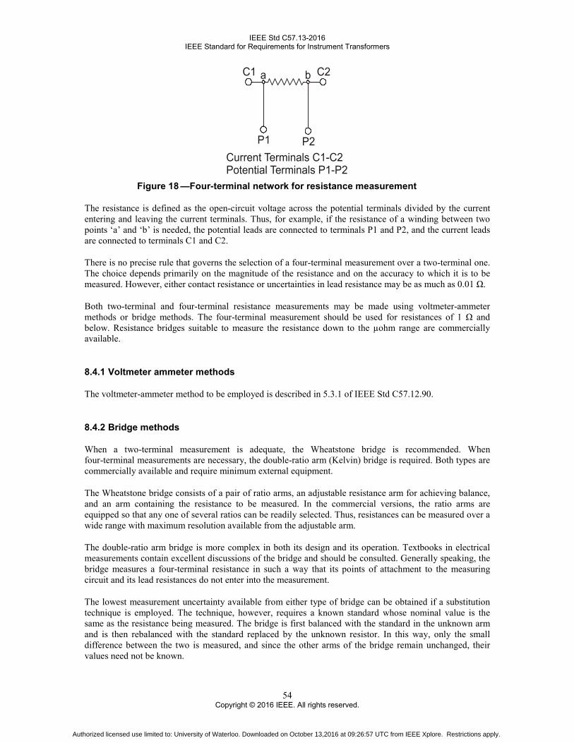
IEEE Std C57.13-2016 IEEE Standard for Requirements for Instrument Transformers
54 Copyright © 2016 IEEE. All rights reserved.
Figure 18 —Four-terminal network for resistance measurement
The resistance is defined as the open-circuit voltage across the potential terminals divided by the current entering and leaving the current terminals. Thus, for example, if the resistance of a winding between two points ‘a’ and ‘b’ is needed, the potential leads are connected to terminals P1 and P2, and the current leads are connected to terminals C1 and C2.
There is no precise rule that governs the selection of a four-terminal measurement over a two-terminal one. The choice depends primarily on the magnitude of the resistance and on the accuracy to which it is to be measured. However, either contact resistance or uncertainties in lead resistance may be as much as 0.01 Ω.
Both two-terminal and four-terminal resistance measurements may be made using voltmeter-ammeter methods or bridge methods. The four-terminal measurement should be used for resistances of 1 Ω and below. Resistance bridges suitable to measure the resistance down to the µohm range are commercially available.
8.4.1 Voltmeter ammeter methods
The voltmeter-ammeter method to be employed is described in 5.3.1 of IEEE Std C57.12.90.
8.4.2 Bridge methods
When a two-terminal measurement is adequate, the Wheatstone bridge is recommended. When four-terminal measurements are necessary, the double-ratio arm (Kelvin) bridge is required. Both types are commercially available and require minimum external equipment.
The Wheatstone bridge consists of a pair of ratio arms, an adjustable resistance arm for achieving balance, and an arm containing the resistance to be measured. In the commercial versions, the ratio arms are equipped so that any one of several ratios can be readily selected. Thus, resistances can be measured over a wide range with maximum resolution available from the adjustable arm.
The double-ratio arm bridge is more complex in both its design and its operation. Textbooks in electrical measurements contain excellent discussions of the bridge and should be consulted. Generally speaking, the bridge measures a four-terminal resistance in such a way that its points of attachment to the measuring circuit and its lead resistances do not enter into the measurement.
The lowest measurement uncertainty available from either type of bridge can be obtained if a substitution technique is employed. The technique, however, requires a known standard whose nominal value is the same as the resistance being measured. The bridge is first balanced with the standard in the unknown arm and is then rebalanced with the standard replaced by the unknown resistor. In this way, only the small difference between the two is measured, and since the other arms of the bridge remain unchanged, their values need not be known.
Authorized licensed use limited to: University of Waterloo. Downloaded on October 13,2016 at 09:26:57 UTC from IEEE Xplore. Restrictions apply.

IEEE Std C57.13-2016 IEEE Standard for Requirements for Instrument Transformers
55 Copyright © 2016 IEEE. All rights reserved.
8.4.3 Reference temperature measurements
The reference temperature of the winding shall be determined accurately when measuring the winding resistance of the relaying accuracy current transformers and for use in temperature rise tests. The temperature of the winding shall not be assumed to be the same as the surrounding air.
The resistance measurements shall be made on a transformer only when the winding temperature is stable. The temperature is considered stable if the external surface temperature of dry-type transformers or top liquid temperature of oil-filled transformers does not vary more than 1 ºC in a 1-hour period.
8.5 Dielectric tests
Dielectric tests should be made with the transformer at room temperature, and unless otherwise specified, the voltage should be measured in accordance with IEEE Std 4.
When tests are required on bushings or insulators separately from the transformers, the tests shall be made in accordance with IEEE Std C57.19.00.
8.5.1 Factory dielectric tests
The purpose of dielectric tests in the factory is to check the insulation and workmanship and to demonstrate that the transformer has been designed to withstand the specified insulation tests.
Impulse tests, when required, shall precede the low-frequency tests.
8.5.2 Dielectric tests by the user
It is recognized that the dielectric tests impose a severe stress on the insulation and, if applied frequently, will hasten breakdown or may cause breakdown. The stress imposed, of course, is more severe the higher the value of the applied voltage. Hence, periodic testing may not be advisable.
It is recommended that initial user tests of insulation should not be in excess of 75% of the factory test voltage; that for old apparatus rebuilt in the field, tests should not be in excess of 75% of the factory test voltage; and the periodic insulation tests by the user should not be in excess of 65% of the factory test voltage. Tests made by the user for design approval may be made at 100% of the factory test voltage.
8.5.3 Applied voltage tests
The terminal ends and taps brought out of the case from the winding under test shall all be joined together and connected to the line terminal of the testing transformer. All other terminals and parts (including tank and core, if accessible) should be connected to ground and to the other terminal of the testing transformer. The ground connection between the apparatus being tested and the testing transformer shall be a substantial metallic circuit.
Wire of sufficient size and suitable arrangement to prevent excessive partial discharge (corona) at the test voltage should be used in connecting the respective taps, line terminals, and the test transformer together. Care shall be taken to keep the wire on the high-voltage side well away from the ground. No appreciable impedance should be placed between the testing transformer and the one under test.
Authorized licensed use limited to: University of Waterloo. Downloaded on October 13,2016 at 09:26:57 UTC from IEEE Xplore. Restrictions apply.

IEEE Std C57.13-2016 IEEE Standard for Requirements for Instrument Transformers
56 Copyright © 2016 IEEE. All rights reserved.
It is recommended that a suitable current-sensitive failure detection device be provided. The reason for this is that the voltage change across the test transformer at failure may not easily be detected by observation of the input voltmeter.
As a safety precaution, a relief gap set at a voltage 10% to 20% in excess of the specified test voltage should be connected during the applied voltage test. For instrument transformers to be tested at 50 kV or less, it is permissible to omit the relief gap (see 8.5).
The applied test voltage should be started at one third or less of full value and increased gradually to full value in not more than 15 s. After being held for 1 minute, it should be reduced gradually in not more than 15 s to one third of the maximum value or less and the circuit opened.
The applied voltage test requirements for insulated-neutral-terminal types of voltage transformers are specified in 4.5.
The test frequency shall be 60 Hz.
8.5.4 Induced voltage tests
These tests are made by applying voltage to one winding with all the other windings open. One end of each winding shall be grounded during this test. Usually the voltage is applied to the low-voltage winding. When the voltage across any winding will exceed 50 kV during this test, some means should be provided to verify the voltage.
As this test (if made at rated frequency) overexcites the transformer under test, the frequency of the applied voltage should be such as to prevent saturation of the core. Ordinarily this requirement necessitates the use of a frequency of 120 Hz or more when exciting 60 Hz units. For those types that have large distributed capacitance, the excitation current increases with the frequency of the applied voltage, making it necessary to guard against an exciting current that will exceed 200% normal load current based on the thermal rating. When frequencies higher than 120 Hz are used, the severity of the test is abnormally increased, and for this reason, the duration of the test should be reduced in accordance with Table 20.
The voltage should be started at one-third or less of the full value and be increased gradually to full value in not more than 15 s. After being held for the duration of time specified in Table 20, it should be reduced gradually in not more than 15 s to one-third the maximum value, or less, and the circuit opened.
Voltage transformers in polyphase metering equipment may be tested with single-phase voltage. Usually the specified test voltage is applied to one of the windings on each core with the neutral ends of the open windings grounded.
Table 20 —Full voltage duration for induced voltage tests
Frequency (Hz)
Duration (s)
120 or less 60 180 40 240 30 360 20 400 18
Authorized licensed use limited to: University of Waterloo. Downloaded on October 13,2016 at 09:26:57 UTC from IEEE Xplore. Restrictions apply.

IEEE Std C57.13-2016 IEEE Standard for Requirements for Instrument Transformers
57 Copyright © 2016 IEEE. All rights reserved.
8.6 Partial discharge measurement
Partial discharge (PD) tests are intended to determine the freedom of internal insulation from damaging internal discharges.
The preferred arrangement for making the partial discharge test is to have the instrument transformer under test to be fully assembled prior to conducting the test; however, during the partial discharge test, if external fittings or hardware on the assembled transformer being tested results in interfering with the test, they may be removed or provided with supplementary shielding.
Oil-filled, gas-filled, and dry-type instrument transformers 5 kV nominal system voltage and above shall be given a partial discharge test as a routine test. No test shall be made on terminals that are intended to be grounded.
At the discretion of the manufacturer, the induced or applied voltage and partial discharge tests may be performed together.
The background noise level shall be in accordance with IEC 60270.
If necessary, external electrodes may be used for the primary terminal and the ground of the transformer. The test method shall be in accordance with IEC 60270. For typical test circuits see IEC 60270.
When using a 60 Hz pre-stress voltage it shall be maintained for a minimum of 60 s; where a higher frequency is used the duration may be reduced as per Table 20. Subsequently the test voltage shall be reduced to the level of the prescribed extinction voltage, which shall then be maintained for a minimum of 30 s. The partial discharge intensity shall be measured during this time. It is recommended that the reduction from the pre-stress to test voltage be done over approximately 10 s.
The transformer shall be considered as having met the requirements if the partial discharge intensity measured at the prescribed extinction voltage level is equal to or less than 10 pC for oil-filled or gas-filled transformers, and 50 pC for dry-type insulation systems.12
For current transformers the test voltage shall be applied to H1 and H2. All secondary terminals and the base shall be grounded.
For line-to-line voltage transformers, the partial discharge shall be measured for each of the following connections:
a) The test voltage shall be applied to H1. H2, one end of each secondary winding, and the base shall be grounded.
b) The test voltage shall be applied to H2. H1, one end of each secondary winding, and the base shall be grounded.
For line-to-ground voltage transformers the test voltage shall be applied to H1. H2, one end of each secondary winding and the base shall be grounded.
For combination units containing both a voltage and current transformer the pre-stress and prescribed extinction test voltages shall be based upon the guidelines established below for voltage transformers. The connections for the combination units are to be made with the voltage applied to H1 and H2 with the current transformer secondary terminals grounded one secondary of the voltage transformer grounded and the base grounded.
12 It is recommended that the actual measured partial discharge extinction voltage be recorded.
Authorized licensed use limited to: University of Waterloo. Downloaded on October 13,2016 at 09:26:57 UTC from IEEE Xplore. Restrictions apply.
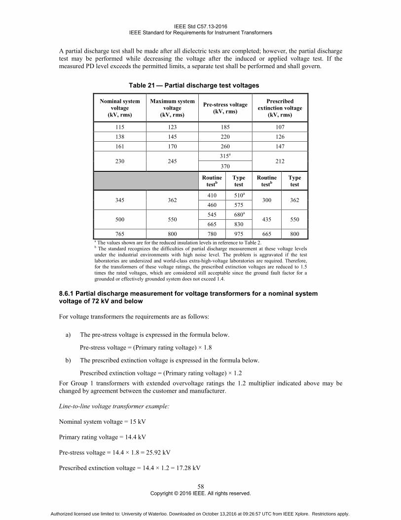
IEEE Std C57.13-2016 IEEE Standard for Requirements for Instrument Transformers
58 Copyright © 2016 IEEE. All rights reserved.
A partial discharge test shall be made after all dielectric tests are completed; however, the partial discharge test may be performed while decreasing the voltage after the induced or applied voltage test. If the measured PD level exceeds the permitted limits, a separate test shall be performed and shall govern.
Table 21 — Partial discharge test voltages
Nominal system voltage
(kV, rms)
Maximum system voltage
(kV, rms)
Pre-stress voltage (kV, rms)
Prescribed extinction voltage
(kV, rms)
115 123 185 107 138 145 220 126 161 170 260 147
230 245 315a
212 370
Routine testb
Type test
Routine testb
Type test
345 362 410 510a
300 362 460 575
500 550 545 680a
435 550 665 830
765 800 780 975 665 800 a The values shown are for the reduced insulation levels in reference to Table 2. b The standard recognizes the difficulties of partial discharge measurement at these voltage levels under the industrial environments with high noise level. The problem is aggravated if the test laboratories are undersized and world-class extra-high-voltage laboratories are required. Therefore, for the transformers of these voltage ratings, the prescribed extinction voltages are reduced to 1.5 times the rated voltages, which are considered still acceptable since the ground fault factor for a grounded or effectively grounded system does not exceed 1.4.
8.6.1 Partial discharge measurement for voltage transformers for a nominal system voltage of 72 kV and below
For voltage transformers the requirements are as follows:
a) The pre-stress voltage is expressed in the formula below.
Pre-stress voltage = (Primary rating voltage) × 1.8
b) The prescribed extinction voltage is expressed in the formula below.
Prescribed extinction voltage = (Primary rating voltage) × 1.2 For Group 1 transformers with extended overvoltage ratings the 1.2 multiplier indicated above may be changed by agreement between the customer and manufacturer.
Line-to-line voltage transformer example:
Nominal system voltage = 15 kV
Primary rating voltage = 14.4 kV
Pre-stress voltage = 14.4 × 1.8 = 25.92 kV
Prescribed extinction voltage = 14.4 × 1.2 = 17.28 kV
Authorized licensed use limited to: University of Waterloo. Downloaded on October 13,2016 at 09:26:57 UTC from IEEE Xplore. Restrictions apply.

IEEE Std C57.13-2016 IEEE Standard for Requirements for Instrument Transformers
59 Copyright © 2016 IEEE. All rights reserved.
Line-to-ground voltage transformer example:
Nominal system voltage = 15 kV
Detail = 7200 / 12470GY
Primary rating voltage = 7.2 kV
Pre-stress voltage = 7.2 × 1.8 = 12.96 kV
Prescribed extinction voltage = 7.2 × 1.2 = 8.64 kV
8.6.2 Partial discharge measurement for current transformers for a nominal system voltage of 72 kV and below
For current transformers the requirements are as follows:
a) The pre-stress voltage is expressed in the formula below
Pre-stress voltage = (Nominal system voltage) × 1.8
b) The prescribed extinction voltage is expressed in the formula below
Prescribed extinction voltage = (Nominal system voltage / √3) × 1.2
Medium voltage current transformer example:
Nominal system voltage = 15 kV
Pre-stress voltage = 15 × 1.8 = 27 kV
Prescribed extinction voltage = (15 / √3) × 1.2 = 10.4 kV
9. Test procedures applicable to current transformers
9.1 Ratio and phase angle measurement and calculations
9.1.1 Accuracy calculations for current transformers
For current transformers having substantially continuous ring cores, uniformly distributed secondary windings, and having either a centrally located primary conductor or a uniformly distributed primary winding, the values of ratio, ratio error, and phase angle may be obtained by calculation (computation) from the obtained secondary excitation characteristics at the rated frequency.
Although the following indirect test will lead to results which are close to the results obtained in the direct test, the routine accuracy tests for the metering current transformers shall always be performed as a direct test. On the other hand, the alternative method is suitable for on-site measurements, and for monitoring purposes.
Authorized licensed use limited to: University of Waterloo. Downloaded on October 13,2016 at 09:26:57 UTC from IEEE Xplore. Restrictions apply.

IEEE Std C57.13-2016 IEEE Standard for Requirements for Instrument Transformers
60 Copyright © 2016 IEEE. All rights reserved.
For current transformers with negligible leakage fluxes, the equivalent circuit shown in Figure 19 and the vector diagram shown in Figure 20 are suitable for calculations. It shall be noted that the alternative (indirect) method never considers the influence of stray fluxes entering the core from the adjacent conductors.
Figure 19 —Simplified equivalent circuit of current transformer
The following definitions apply to Figure 19:
Ns is the secondary turns on the current transformer
Np is the primary turns on the current transformer
Rs is the resistance of transformer secondary
Rb is the resistance of secondary burden
Xb is the reactance of secondary burden
Ip is the primary current
Is is the secondary current
Ie is the exciting current
Im is the magnetizing current
Ia is the current associated with the loss (or active component)
Xm is the reactive component of the magnetizing impedance
Authorized licensed use limited to: University of Waterloo. Downloaded on October 13,2016 at 09:26:57 UTC from IEEE Xplore. Restrictions apply.

IEEE Std C57.13-2016 IEEE Standard for Requirements for Instrument Transformers
61 Copyright © 2016 IEEE. All rights reserved.
Rm is the resistive component of the magnetizing impedance
Ep is the primary voltage
Eo is induced voltage in magnetizing circuit
Es is the secondary terminal voltage
Assuming that electric and magnetic components of transformer and burden are linear, and primary current is sinusoidal, then performance of this transformer can be illustrated by the following vector diagram.
Figure 20 —Vector diagram of Figure 19
In Figure 20, IS represents the secondary current. It flows through the total secondary impedance ZΣ of the secondary winding and the burden which determines the magnitude and direction of the induced voltage EO and of the flux Φ which is perpendicular to the voltage vector. This flux is maintained by the exciting current Ie, having a magnetizing component Im parallel to the flux Φ, and a loss (or active) component Ia parallel to the voltage. The vector sum of the secondary current IS and the exciting current Ie is the vector I’P representing the primary current IP divided by the turns ratio (number of secondary turns to number of primary turns).
For a current transformer with the turns ratio equal to the rated transformation ratio, the difference in the lengths of the vectors IS and I’P, related to the length of I’P, is the current ratio error (RE), and the angular difference β is a phase angle (PA).
Authorized licensed use limited to: University of Waterloo. Downloaded on October 13,2016 at 09:26:57 UTC from IEEE Xplore. Restrictions apply.

IEEE Std C57.13-2016 IEEE Standard for Requirements for Instrument Transformers
62 Copyright © 2016 IEEE. All rights reserved.
9.1.2 Calculation of current transformer performance from secondary excitation characteristics and equivalent circuits13
9.1.2.1 Determination of current transformer turns ratio
A substantially sinusoidal voltage ES is injected between secondary terminals X1 and X2 of the CT. The voltage EP across the terminals H1and H2, and exciting current Ie are measured. The value of ES should be selected to obtain measureable voltages on both windings but shall not exceed the knee point voltage EK. Turns ratio may be determined from the relationship:
S O
P P
N EN E
= (9)
where
NS is turns on the secondary winding NP is turns on the primary winding EO is (ES – Ie×RS) RS is the resistance of the secondary winding at 75 °C
In the case of window-type CTs an artificial primary winding has to be established. If they are installed on equipment, consideration shall be taken as to what the artificial primary winding used in this test is comprised of.
9.1.2.2 Calculation of current transformer ratio error and phase angle
Determine the equivalent operational secondary voltage ET at the desired secondary current IS (i.e., 5 A, 0.5 A, or some other point of interest) and burden
T SE I ZS= × (10)
where
( )2 2S B BZ R R XS = + + (11)
RB is the resistance component of the secondary burden XB is the reactive component of the secondary burden
Inject the substantially sinusoidal voltage ET between secondary terminals X1 and X2 of the CT. The secondary exciting current Ie is measured.
Employing fundamental formulas for current transformer (see Harris [B9]), the accuracy performance yields:
Ratio Error (RE) = e
S
I sin( )I
× ϕ+ θ
(12)
13 Refer to 8.2.3 for additional information.
Authorized licensed use limited to: University of Waterloo. Downloaded on October 13,2016 at 09:26:57 UTC from IEEE Xplore. Restrictions apply.

IEEE Std C57.13-2016 IEEE Standard for Requirements for Instrument Transformers
63 Copyright © 2016 IEEE. All rights reserved.
Phase Angle (PA) = e
S
I cos( )I
× ϕ+ θ
(13)
where
Φ is the angle between impedance ZΣ and resistance RΣ = (RS + RB) θ is the angle between apparent power VA and active power W
9.1.2.3 Calculation of current transformer composite error
From Equation (10) determine the equivalent operational secondary voltage ET at some desired secondary current IS (rated current, 20 times rated current, or some other point of interest) and burden. Inject the substantially sinusoidal voltage ET between secondary terminals X1 and X2 of the CT. The secondary exciting current Ie is measured.
The percent composite error = e
S
I 100 %I
×
(14)
9.1.3 Application of calculating methods to type C relaying accuracy current transformers
Since T-type current transformers have appreciable leakage flux entering the core, they cannot be represented adequately by an equivalent circuit. This type of current transformer does not lend itself to simple, accurate calculations. Therefore, these calculations are primarily applicable to types C, i.e., bushing-type current transformers for relaying service.
Since these transformers are generally multiratio, the most useful form in which the transformer secondary excitation characteristics may be given is a family of curves similar to Figure 1 showing the excitation voltage and currents on the secondary winding turns base for each ratio. These curves are usually determined from test data taken on a typical unit of a given design by the method covered in 8.2.3.
9.2 Demagnetization
Two methods are presented below for demagnetizing current transformers:
a) Method 1. Connect the current transformer in the test circuit as shown in Table 21. Apply enough current to the high-turn winding (usually X1−X2) to saturate the core of the transformer as determined by the ammeter and voltmeter readings; then slowly reduce the current to zero. The rated secondary current of the transformer shall not be exceeded.
Authorized licensed use limited to: University of Waterloo. Downloaded on October 13,2016 at 09:26:57 UTC from IEEE Xplore. Restrictions apply.
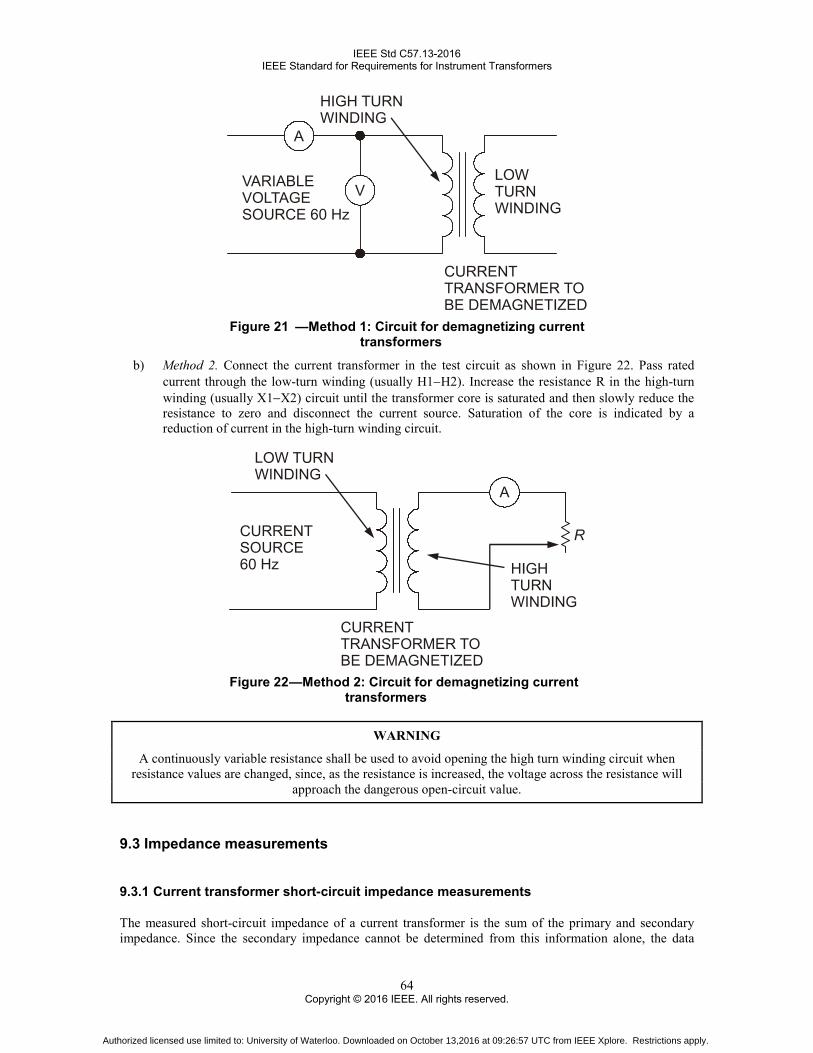
IEEE Std C57.13-2016 IEEE Standard for Requirements for Instrument Transformers
64 Copyright © 2016 IEEE. All rights reserved.
Figure 21 —Method 1: Circuit for demagnetizing current
transformers
b) Method 2. Connect the current transformer in the test circuit as shown in Figure 22. Pass rated current through the low-turn winding (usually H1−H2). Increase the resistance R in the high-turn winding (usually X1−X2) circuit until the transformer core is saturated and then slowly reduce the resistance to zero and disconnect the current source. Saturation of the core is indicated by a reduction of current in the high-turn winding circuit.
Figure 22 —Method 2: Circuit for demagnetizing current
transformers
WARNING
A continuously variable resistance shall be used to avoid opening the high turn winding circuit when resistance values are changed, since, as the resistance is increased, the voltage across the resistance will
approach the dangerous open-circuit value.
9.3 Impedance measurements
9.3.1 Current transformer short-circuit impedance measurements
The measured short-circuit impedance of a current transformer is the sum of the primary and secondary impedance. Since the secondary impedance cannot be determined from this information alone, the data
Authorized licensed use limited to: University of Waterloo. Downloaded on October 13,2016 at 09:26:57 UTC from IEEE Xplore. Restrictions apply.

IEEE Std C57.13-2016 IEEE Standard for Requirements for Instrument Transformers
65 Copyright © 2016 IEEE. All rights reserved.
obtained is of little value in the calculation of ratio and phase angle characteristics. However, it is of value in determining the burden imposed on main transformers by auxiliary transformers.
Except for current, the quantities measured in making impedance measurements on current transformers are extremely small and great care shall be exercised in order to obtain accurate results.
For the purpose of impedance measurements, current transformers can be divided into the following three types, according to their physical details:
a) Type 1: Bushing-type, window-type, or bar-type, with turns well distributed about the core. In current transformers of this type, the leakage reactance is extremely small and the impedance may be considered to be the resistance of the whole winding or that part to be used if it is well distributed. The manufacturer should be consulted if the winding distribution is not known.
b) Type 2: Wound type in which the high-current (primary) terminals are at opposite ends of the transformer. Transformers of this type should be excited from the high-current winding with the low-current winding short circuited, because a short circuit on the high-current winding will introduce appreciable error in the measurement due to the added impedance of the short-circuiting connections.
It is recommended that the three-voltmeter method, as described in 10.2.1, be used for impedance measurement on this type of transformer.
c) Type 3: Wound type in which the high-current (primary) leads are brought out parallel to each other through a single bushing. Current transformers of this type may be excited from either the high-current or the low-current winding with the other winding short circuited.
Either the three-voltmeter method or the wattmeter, voltmeter, ammeter method can be used for impedance measurements on transformers of this type, depending on which winding is excited.
9.4 Polarity
9.4.1 Comparison with a transformer of known polarity
To determine the polarity of current transformers using this method, do the following:
a) Connect the transformers as shown in Figure 23.
b) Energize the circuit from a controlled current source so that the test current flows in the H1−H2 windings as shown in Figure 23.
c) If the ammeter reads the sum of the currents in the high-turn windings, the polarity of the unknown transformer is reversed. If the ammeter reads the difference of currents in the high-turn windings, the polarity of the unknown transformer is as marked.
Authorized licensed use limited to: University of Waterloo. Downloaded on October 13,2016 at 09:26:57 UTC from IEEE Xplore. Restrictions apply.

IEEE Std C57.13-2016 IEEE Standard for Requirements for Instrument Transformers
66 Copyright © 2016 IEEE. All rights reserved.
Figure 23 —Polarity by comparison with current transformer of known polarity
10. Test procedures applicable to voltage transformers
10.1 Ratio and phase angle measurement and calculations
10.1.1 Accuracy calculations for voltage transformers
Several methods are available for calculating the accuracy of voltage transformers at different burdens. These methods, utilizing winding impedances and core excitation characteristics, are subject to some limitations and give results having less precision than those methods that employ a combination of test and calculation.
The latter methods, using measured values of true ratio and phase angle at zero burden and one other burden within the maximum standard burden rating of the transformer, yield results having a high degree of precision. This is possible because both the ratio and the phase angle of a voltage transformer give practically straight lines when plotted against secondary current at a given voltage, power factor, and frequency.
10.1.2 Calculation of voltage transformer ratio and phase angle from known zero and rated burden data
In this method, the true ratio and phase angle of a voltage transformer are known at both zero burden and one other burden, either a rated standard burden or, more conveniently, a pure resistive or capacitive burden, for a given voltage and frequency. At the same voltage and frequency, the accuracy for any other burden and power factor may be calculated from the following equations:14
Bo is the zero burden for which RCF and θ are known Bt is the burden for which RCF and θ are known Bc is the burden for which RCF and θ are to be calculated θt is the power factor angle of burden Bt (in radians) θc is the power factor angle of burden Bc (in radians)
14 These equations are approximations. Although they yield accurate results for many cases, the user should be aware that for large burdens (e.g., Z or ZZ), intolerable errors may be introduced unless the volt-amperes of the known burden are equal to or greater than those of the unknown burden, and the values for the known and the zero burdens are measured accurately. This problem is minimized for all cases if the magnitude of the known burden is made nominally equal to the magnitude of the rated burden of the transformer under test.
Authorized licensed use limited to: University of Waterloo. Downloaded on October 13,2016 at 09:26:57 UTC from IEEE Xplore. Restrictions apply.

IEEE Std C57.13-2016 IEEE Standard for Requirements for Instrument Transformers
67 Copyright © 2016 IEEE. All rights reserved.
NOTE 1—θt and θc are positive angles for lagging power factors.
RCFo is the transformer correction factor for burden Bo RCFt is the transformer correction factor for burden Bt RCFc is the transformer correction factor for burden Bc γo is the transformer phase angle for burden Bo [in radians] γt is the transformer phase angle for burden Bt [in radians] γc is the transformer phase angle for burden Bc [in radians]
NOTE 2—γ is considered positive when the secondary voltage leads the primary voltage.
d t oRCF RCF RCF= − (15)
which equals difference between the transformer ratio correction factors for burdens Bt and Bo
d t oγ = γ − γ (16)
which equals the difference between the transformer phase angles burdens Bt and Bo, in radians
[ ]cc o d t c d t c
t
BRCF RCF RCF cos( ) sin( )B
= + × × θ −θ + γ × θ −θ
(17)
[ ]cc o d t c d t c
t
B cos( ) RCF sin( )B
γ = γ + × γ × θ −θ − × θ −θ
[in radians] (18)
NOTE 3— Multiply radians by 1000 to obtain milliradians (mrad). If minutes are desired, multiply by 3438.
NOTE 4— These equations provide an analytical determination of voltage transformer accuracy. Although they are long, a simple computer or programmable calculator program can be written to perform the necessary calculations quickly and accurately. Also, it has been shown that graphical solutions of these equations by means of special scaled polar coordinate paper and a protractor are sufficiently accurate for most revenue-metering applications.
The equations for RCFc and γc above reduce to the following simpler form in the case where the burden for RCF and γ are known to be at unity power factor.
[ ]cc o d c d c
t
BRCF RCF RCF cos( ) sin( )B
= + × × θ − γ × θ
(19)
[ ]cc o d c d c
t
B cos( ) RCF sin( )B
γ = γ + × γ × θ + × θ
[in radians] (20)
where
Bt is the unity power factor burden γd is in radians
Authorized licensed use limited to: University of Waterloo. Downloaded on October 13,2016 at 09:26:57 UTC from IEEE Xplore. Restrictions apply.
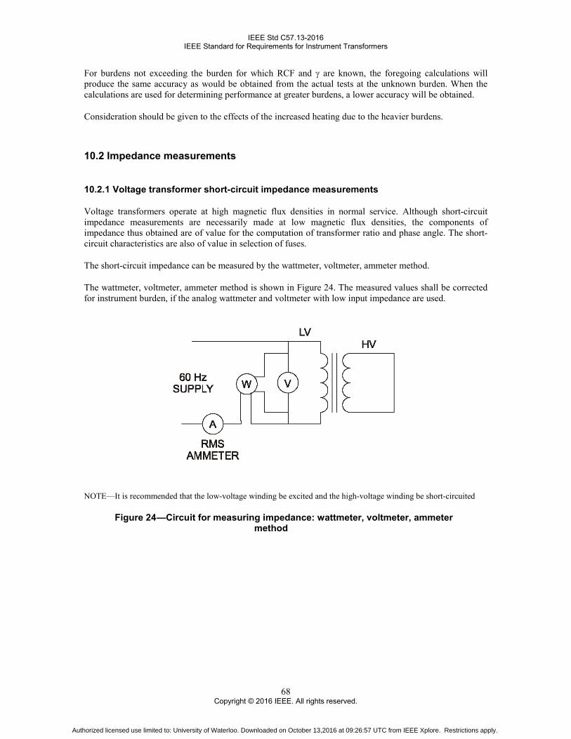
IEEE Std C57.13-2016 IEEE Standard for Requirements for Instrument Transformers
68 Copyright © 2016 IEEE. All rights reserved.
For burdens not exceeding the burden for which RCF and γ are known, the foregoing calculations will produce the same accuracy as would be obtained from the actual tests at the unknown burden. When the calculations are used for determining performance at greater burdens, a lower accuracy will be obtained.
Consideration should be given to the effects of the increased heating due to the heavier burdens.
10.2 Impedance measurements
10.2.1 Voltage transformer short-circuit impedance measurements
Voltage transformers operate at high magnetic flux densities in normal service. Although short-circuit impedance measurements are necessarily made at low magnetic flux densities, the components of impedance thus obtained are of value for the computation of transformer ratio and phase angle. The short-circuit characteristics are also of value in selection of fuses.
The short-circuit impedance can be measured by the wattmeter, voltmeter, ammeter method.
The wattmeter, voltmeter, ammeter method is shown in Figure 24. The measured values shall be corrected for instrument burden, if the analog wattmeter and voltmeter with low input impedance are used.
NOTE—It is recommended that the low-voltage winding be excited and the high-voltage winding be short-circuited
Figure 24 —Circuit for measuring impedance: wattmeter, voltmeter, ammeter method
Authorized licensed use limited to: University of Waterloo. Downloaded on October 13,2016 at 09:26:57 UTC from IEEE Xplore. Restrictions apply.

IEEE Std C57.13-2016 IEEE Standard for Requirements for Instrument Transformers
69 Copyright © 2016 IEEE. All rights reserved.
10.3 Polarity
10.3.1 Comparison with a transformer of known polarity
To determine the polarity of voltage transformers using this method, do the following:
a) Connect the high-turn windings of the two transformers in parallel, as shown in Figure 25, by connecting H1 of the known transformer to H1 of the unknown transformer and H2 of the known transformer to H2 of the unknown transformer.
b) Connect the low-turn windings through a voltmeter, as shown in Figure 25 by connecting X1 of the known transformer to X1 of the unknown transformer and X2 of the known transformer to one voltmeter terminal and X2 of the unknown transformer to the other voltmeter terminal.
c) Energize the circuit at terminals H1−H2 from a controlled 60 Hz voltage source.
d) If the voltmeter reads zero, the polarity of the unknown transformer is as marked. If the voltmeter reads the sum of the voltages of the low-turn windings, the polarity of the unknown transformer is reversed.
WARNING
High voltages will be present on the high-voltage terminals of both transformers. Safety precautions should be taken.
Figure 25 —Polarity by comparison with voltage transformer of same ratio and
known polarity
Authorized licensed use limited to: University of Waterloo. Downloaded on October 13,2016 at 09:26:57 UTC from IEEE Xplore. Restrictions apply.

IEEE Std C57.13-2016 IEEE Standard for Requirements for Instrument Transformers
70 Copyright © 2016 IEEE. All rights reserved.
11. Type test procedures applicable to instrument transformers
11.1 Short-time characteristics
11.1.1 Short-time mechanical rating tests
The test to demonstrate the short-time mechanical current rating of a current transformer shall be made by subjecting the current transformer, with the secondary winding short-circuited; to a fully asymmetrical short-circuit current of the duration of at least six cycles. The magnitude of the first asymmetrical peak current shall be 2.7 times the thermal short-time current rating with the other peaks decreasing in magnitude. This test may be combined with the thermal short-time test as long as the first peak satisfies the mechanical rating and the remaining peak values are not less than the thermal rating for the duration of the test.
The test to demonstrate the mechanical short-circuit capability of a voltage transformer shall be made with rated voltage maintained on the primary for 1 s with the secondary terminals short-circuited. The test shall be performed with the secondary windings paralleled if multiple secondary windings are present and by short-circuiting the taps that result in the highest current. As an alternative, the test could be performed by short-circuiting the primary winding and applying the rated secondary voltage for 1 s. The test shall be performed with the secondary windings paralleled and by applying the voltage between the taps that result in the highest current.
11.1.2 Thermal short-time rating calculations
The calculation of temperature rise of a winding under short-time conditions is based on the assumption that heating is adiabatic, i.e., that all of the energy developed in the winding during the period of the short circuit (5 s or less) is stored as heat in the winding.
It is also assumed that the starting temperature of the winding when the short circuit occurs is the maximum hottest-spot temperature of the winding at 30 °C ambient temperature under continuous loading at (1) the continuous thermal current rating for a current transformer or (2) the maximum rated standard burden and 110% of rated voltage for a voltage transformer. Where this hottest-spot winding temperature is not established by test, the limits of hottest-spot temperature rise (specified in Table 4) for 30 °C ambient shall be used.
The calculated maximum temperature attained by the winding during the short circuit shall not exceed the limits specified in 6.6.2 for a current transformer or in Clause 7 for a voltage transformer.
The general equation of winding temperature under short-circuit conditions is most conveniently expressed and used as the current density that will produce the maximum permissible temperature in the winding under the conditions specified above. Thus,
2
m
s
20
T KTI C (T 20) ln
A 2 t 1 K
+ θ+ + θ × + = × ×ρ × +
(21)
where
I is the short-circuit current, in amperes
Authorized licensed use limited to: University of Waterloo. Downloaded on October 13,2016 at 09:26:57 UTC from IEEE Xplore. Restrictions apply.

IEEE Std C57.13-2016 IEEE Standard for Requirements for Instrument Transformers
71 Copyright © 2016 IEEE. All rights reserved.
A is the conductor cross section in centimeters squared C is the average thermal capacitance per unit volume, in wattseconds/(degrees Celsius × centimeters
cubed) ρ20 is the specific resistance at 20 °C in ohm-cm t is the duration of short circuit, in seconds T equals 234.5 °C for copper equals 225 °C for EC aluminum θs is the starting temperature, in degrees Celsius θm is the maximum temperature, in degrees Celsius K is the ratio of all stray conductor loss to the dc I2R loss of the winding at the starting temperature,
θs ln is the natural logarithm
This general equation may be simplified for most practical applications, since short-time thermal ratings are based on a short-circuit duration of 1 s, and except for large current transformer primary bars, K is usually negligible.
For copper (100% IACS):
ρ20 = 1.725 × 10⁻⁶ Ω-cm C = 3.575 Ws/(°C × cm3) T = 234.5 °C
and, for the above conditions,
2
m2
s
234.5I A16240 lnA 234.5 cm
+ θ = × + θ (22)
For aluminum (EC, 62% IACS):
ρ20 = 2.781 × 10⁻⁶ Ω-cm C = 2.630 Ws/(°C × cm3) T = 225 °C
and, for the above conditions,
2
m2
s
225I A10760 lnA 225 cm
+ θ = × + θ (23)
If θm is taken as 250 °C for copper and as 200 °C for EC aluminum (see 6.6.2), and if θs is taken as 95 °C for 55 °C rise types, 110 °C for 65 °C rise types, and 140 °C for 80 °C rise types (see Table 4), then:
For copper:
I/A = 14 260 A/cm2 for 55 °C rise types
I/A = 13 420 A/cm2 for 65 °C rise types
I/A = 11 660 A/cm2 for 80 °C rise types
Authorized licensed use limited to: University of Waterloo. Downloaded on October 13,2016 at 09:26:57 UTC from IEEE Xplore. Restrictions apply.
IEEE Std C57.13-2016 IEEE Standard for Requirements for Instrument Transformers
72 Copyright © 2016 IEEE. All rights reserved.
For aluminum:
I/A = 8110 A/cm2 for 55 °C rise types
I/A = 7430 A/cm2 for 65 °C rise types
I/A = 5940 A/cm2 for 80 °C rise types
11.2 Temperature rise tests
11.2.1 General
All temperature rise tests shall be made under the normal conditions of the means, or method, of cooling.
All temperature rise tests shall be made with the transformer under test in the orientation and under the conditions for which it is designed to operate. If the transformer is designed for use in any one of several orientations, or under several possible conditions, the test shall be made in the orientation and condition that is expected to result in the greatest temperature rise.
The transformer shall be mounted in a normal manner. Mounted in a normal manner shall be interpreted to mean that the heat dissipation due to conduction and radiation shall not be substantially influenced by abnormal heat transfer to, or from, surrounding objects. Transformers shall be completely assembled with normal finish, and if oil-filled, they shall be filled to the recommended level.
Temperature rise tests shall be made in an area as with a wind speed of 0.5 m/s or less.
The design shall be considered as having met the requirements of 4.6 if the temperature rise is in accordance with Table 4 and terminal temperature rise is in accordance with Table 5.
11.2.2 Ambient or cooling air temperature
The ambient temperature shall be the temperature of the air surrounding the transformer under test.
The ambient temperature shall be not less than 10 °C nor more than 40 °C during a temperature rise test.
The preferred method of measuring the ambient temperature is by using an ideal identical transformer, or one having similar thermal-time characteristics, and measuring the temperature by the resistance method. The idle transformer shall be located so as to respond to ambient temperature changes in the same manner as the transformer under test (see 8.4.3).
When an identical transformer is not available, the temperature of the cooling air shall be determined from the average of the readings of several thermometers or thermocouples (one may be used for small transformers) placed around and approximately at the same level as the center of the maximum vertical heat-dissipating surface of the transformer, at a horizontal distance adequate to prevent the transformer under test from influencing the readings (1 m to 2 m is usually sufficient).
To reduce to a minimum the errors due to time lag between the temperature of the transformers and the variations in the ambient temperature, the thermocouples, or thermometers, shall be placed in suitable containers and shall have such proportions as will require not less than 2 h for the indicated temperature within the container to change 6.3 °C if suddenly placed in air that has a temperature 10 °C higher, or lower, than the previous steady-state indicated temperature within the container.
Authorized licensed use limited to: University of Waterloo. Downloaded on October 13,2016 at 09:26:57 UTC from IEEE Xplore. Restrictions apply.
IEEE Std C57.13-2016 IEEE Standard for Requirements for Instrument Transformers
73 Copyright © 2016 IEEE. All rights reserved.
When the ambient temperature, based on the average readings of the thermometers or thermocouples during one observation period, is not 30 °C, the winding losses will not be the same as the values that would have been obtained at 30 °C ambient conditions. If the temperature rise values obtained are close to the limiting values for the insulation used in the transformer, a correction shall be applied to that part of the temperature rise due to the winding losses.
The corrected temperature rise for current transformers shall be obtained by multiplying the total measured temperature rise by the applicable factor [as shown in Equation (24) and Equation (25)].
Factor for copper windings equals a
264.5234.5+ θ
(24)
Factor for EC aluminum windings equals a
255225+ θ
(25)
where
θa is the ambient temperature at the termination of the temperature rise test
The temperature rise of voltage transformers depends on both the winding losses and the core losses. Only that part of the temperature rise due to the winding losses is affected by the ambient temperature, as the core losses are not appreciably changed over the temperature range in which instrument transformers normally operate.
The part of the temperature rise due to the winding losses shall be corrected by using the applicable factor covered above. To obtain the part of the temperature rise due to winding losses, a temperature rise test shall be made with the voltage transformer secondary winding open-circuited and the values obtained subtracted from the temperature rise values that were obtained under the corresponding condition specified by 13.2.
11.2.3 Temperature rise measurements
Provision shall be made to measure the surface temperature of all metal parts surrounding, or adjacent to, the outlet leads or terminals carrying large currents.
When possible, the top liquid temperature of oil-filled transformers shall be measured by a thermocouple or spirit thermometer immersed to approximately 5 cm below the top liquid surface.
The bulbs of the spirit thermometer or other temperature-reading means used for taking temperatures of the transformer surfaces in air shall be covered by small felt pads, or the equivalent, cemented to the transformer. If thermocouples are used, the leads shall be so arranged that excessive heat is not conducted to or from the junction.
The ultimate average temperature rise of the windings shall be determined by the resistance method whenever practical.
To avoid errors due to the time required for the bridge current to become constant, the time required shall be determined during the measurement of the winding resistance reference temperature. An equal or slightly longer time shall be allowed when making ultimate and cooling rate temperature measurements. Measurements of temperature rise by the resistance method shall not include contact resistances. This may be accomplished by using a four wire method.
Authorized licensed use limited to: University of Waterloo. Downloaded on October 13,2016 at 09:26:57 UTC from IEEE Xplore. Restrictions apply.

IEEE Std C57.13-2016 IEEE Standard for Requirements for Instrument Transformers
74 Copyright © 2016 IEEE. All rights reserved.
The temperature rise shall be considered constant when all temperatures that can be measured without shutdown at intervals of not less than 30 min show three consecutive readings within 1 °C. Temperature rise tests shall not be made by any method that requires shutting off the power for more than 2 min in any 2 hours to establish that a constant temperature has been reached.
11.2.4 Determination of winding temperature at time of shutdown
A correction shall be made for the cooling that occurs from the time that the power is shut off to the time that the hot resistance is measured.
The recommended method of determining the temperature of the winding at the time of shutdown shall be by measuring the resistance of the windings, as the transformer cools, immediately after shutdown and extrapolating to the time of shutdown. At least four measurements shall be made at intervals of not more than 3 min but no less than the time required for the measuring current to stabilize. If the current does not exceed 15% of the rated current of the winding, it may be maintained during the entire period.
11.2.5 Determination of average temperature by the resistance method
The average temperature of a winding shall be determined by Equation (26) or Equation (27)
( )tt o
o
R T TR
θ = × + θ −
(26)
t ot o o
o
R R (T )R
−θ = × + θ + θ
(27)
where
T is for copper equal to 234.5 T is for EC aluminum equal to 225 θt is the temperature in degrees Celsius corresponding to the resistance of the winding at time of
shutdown θo is the temperature in degrees Celsius corresponding to the reference resistance of the winding Rt is the resistance of the winding at time of shutdown Ro is the reference resistance of the winding
The dc resistance measuring equipment shall have a minimum resolution of three significant digits following the first significant digit.
11.2.6 Determination of temperature rise from temperature measurements
The temperature rise is the corrected total temperature minus the ambient temperature at the time the observations were made.
11.2.7 Correction of observed temperature rise for variation in altitude
When tests are made at an altitude not exceeding 1000 m above sea level, no altitude correction shall be applied to the temperature rise.
Authorized licensed use limited to: University of Waterloo. Downloaded on October 13,2016 at 09:26:57 UTC from IEEE Xplore. Restrictions apply.

IEEE Std C57.13-2016 IEEE Standard for Requirements for Instrument Transformers
75 Copyright © 2016 IEEE. All rights reserved.
When tests are made at an altitude that is more than 1000 m above sea level, the temperature rise shall be corrected to 30 °C conditions by the following method:
r mh 10001 0.005
100 − θ = θ × − ×
(28)
where
θr is the temperature rise with standard conditions θm is the measured temperature rise corrected to 30 °C conditions h is the altitude in meters above sea level
11.3 Impulse tests
11.3.1 Impulse test sequence
These tests consist of applying in the following order one reduced full wave, one full wave, two chopped waves, and two full waves.
11.3.1.1 Wave to be used
The wave to be used shall consist of a nominal 1.2 × 50 µs wave. Either, but not both, positive or negative waves may be used. Waves of negative polarity for oil-filled apparatus, and of positive polarity for dry-type or compound-filled apparatus, are recommended and shall be used unless otherwise specified.
The voltage shall be measured and the waveform traces scaled as specified in IEEE Std 4.
11.3.1.2 Reduced full-wave test
For this test, the voltage wave shall have a peak value of between 50% and 70% of the full-wave peak given in Table 2.
11.3.1.3 Chopped-wave test
For this test, the applied voltage wave shall be chopped by a suitable air gap. It shall have a peak value and time to flashover in accordance with Table 2.
To avoid recovery of insulation strength if failure has occurred during a previous impulse, the time interval between the application of the last chopped wave and the final full wave should be minimized and preferably should not exceed 10 min.
11.3.1.4 Full-wave test
For this test, the voltage wave shall have a peak value in accordance with Table 2, and no flashover of the transformer under test or test gap shall occur.
Authorized licensed use limited to: University of Waterloo. Downloaded on October 13,2016 at 09:26:57 UTC from IEEE Xplore. Restrictions apply.

IEEE Std C57.13-2016 IEEE Standard for Requirements for Instrument Transformers
76 Copyright © 2016 IEEE. All rights reserved.
The time interval between application of the last chopped wave and the final full wave shall be minimized to avoid recovery of insulation strength if a failure has occurred prior to the final full wave.
All impulses applied to a transformer shall be recorded if their peak values exceed 40% of the peak of the full-wave value given in Table 2.
When reports require waveform traces, those of the first reduced full wave, the first full wave, the last two chopped waves, and the last full wave of voltage shall represent a record of the successful applications of the impulse test to the transformer.
11.3.1.5 Current transformer connections for impulse test
The impulse voltage shall be applied to all primary leads simultaneously with the secondary windings short-circuited and grounded.
11.3.1.6 Voltage transformer connections for impulse test
The specified test voltage shall be applied to each primary terminal. In testing transformers equipped with fuses, the fuses should be short-circuited. Test voltages shall be applied to the polarity terminal of the high-voltage winding with the opposite lead grounded and to the nonpolarity terminal with the polarity lead grounded.
One terminal of the winding under test shall be grounded directly or through a small resistance if current measurements are to be made. One terminal of each of the other windings may be grounded directly or through a resistor. It is desirable that the voltage on ungrounded terminals of a winding not under test should not exceed 80% of the full-wave voltage for its BIL rating.
In some cases the inductance of the winding is so low that the desired voltage magnitude and duration of the 50% point on the tail of the wave cannot be obtained with available equipment. Low-inductance windings may be tested by inserting a resistor of not more than 500 Ω in the grounded end of the winding. In all such cases, shorter waves may be used (for additional information, see 10.3.1.1 of IEEE Std C57.12.90).
11.3.1.7 Detection of failure during impulse test
Any unexplained differences between the first 100% full wave and the final full wave detected by superimposing the two voltage waveform traces, or any such differences observed by comparing the chopped waves to each other and to the full wave up to the time of flashover, are indications of failure. Deviations may be caused by conditions in the test circuit external to the transformer or by protective devices and should be fully investigated.
Smoke bubbles rising through the liquid in the transformer are definite evidence of failure. Clear bubbles may or may not be evidence of trouble; they may be due to entrapped air. They should be investigated by repeating the test, or by reprocessing the transformer and repeating the test to determine whether a failure has occurred.
In making the chopped-wave test, failure of the chopping gap, or any external part, to flashover, although the voltage waveform traces show a chopped wave, is a definite indication of a flashover either within the transformer or in the test circuit.
Unusual noise within the transformer at the instant of applying the impulse is an indication of trouble.
Authorized licensed use limited to: University of Waterloo. Downloaded on October 13,2016 at 09:26:57 UTC from IEEE Xplore. Restrictions apply.

IEEE Std C57.13-2016 IEEE Standard for Requirements for Instrument Transformers
77 Copyright © 2016 IEEE. All rights reserved.
For instrument transformers with capacitive graded insulation, current waveform traces comparison is mandatory. When the ground current method of detection is used, impulse current in the grounded end of the winding tested is measured. Any unexplained differences detected by superimposing the two current waveform traces of the first 100% full wave and last full wave tests may be an indication of failure. Deviations in the current wave shapes may also be caused by conditions in the test circuit external to the transformers, or by built-in protective devices, and should be investigated fully. It is difficult to shield the measuring circuit completely from the influence of the high voltage of the impulse generator, and some stray voltages are frequently picked up that may produce an erratic record for the first 1 µs or 2 µs. Such influences, if they occur at the start of the current wave, should be disregarded. The ground current method of detection is not applicable for use with chopped-wave tests.
11.4 Partial discharge measurement
The pre-stress and prescribed extinction voltages shall be in accordance with Table 21 or 8.6.2 depending on voltage rating.
Before the test, the setup shall be calibrated for the partial discharge measurement of 10 pC for oil-filled or gas-filled, and 50 pC for dry-type instrument transformers. The measuring method shall be in accordance with IEC 60270.
The background noise level shall be in accordance with IEC 60270.
If necessary, external electrodes may be used for the primary terminals and the ground of the transformer.
As the test voltage is increased, the voltage at which the partial discharge intensity of 10 pC for oil-filled or gas-filled, and 50 pC for dry-type instrument transformers is detected shall be recorded (i.e., the partial discharge inception voltage). The test voltage shall then be increased until it reaches the prestress voltage level which shall be maintained for the duration in accordance with Table 20. Subsequently the test voltage shall be reduced to the prescribed extinction voltage level15 and then maintained for a duration of 30 s within which the partial discharge intensity shall be measured. The actual partial discharge extinction voltage shall be recorded during the reduction from prestress voltage to the prescribed extinction voltage.
If the partial discharge intensity exceeds the limit of 10 pC for oil-filled or gas-filled, and 50 pC for dry-type instrument transformers, the test may be extended, at the manufacturer’s discretion, by up to 10 min at the prescribed extinction voltage level. The test shall be terminated if the measured partial discharge intensity has decreased to less than or equal to 10 pC for oil-filled or gas-filled, and 50 pC for dry-type instrument transformers.
The design shall be considered as having met the requirements if the following are true:
a) No external disruptive discharge or collapse of voltage is observed during the test, and
b) The partial discharge intensity measured at the prescribed extinction voltage level is equal to or less than 10 pC for oil-filled or gas-filled, and 50 pC for dry-type instrument transformers,16 and
c) No internal insulation failure is found by the capacitance and dissipation factor measurement. d) For transformers with a rated voltage less than 10 kV, for dry type molded transformers without
capacitive graded insulation or for bushing current transformers these capacitance and dissipation factor requirements do not apply.
15 The partial discharge intensity may be measured as the test voltage is reduced from the power frequency withstand voltage level. 16 It is recommended that the actual measured partial discharge extinction voltage be recorded.
Authorized licensed use limited to: University of Waterloo. Downloaded on October 13,2016 at 09:26:57 UTC from IEEE Xplore. Restrictions apply.

IEEE Std C57.13-2016 IEEE Standard for Requirements for Instrument Transformers
78 Copyright © 2016 IEEE. All rights reserved.
11.5 Wet voltage withstand tests
11.5.1 Switching impulse voltage test on the primary winding
The test shall be performed only on transformer designs of a nominal system voltage of 345 kV and above.
The voltage shall be applied between the primary terminal and the ground terminal of the transformer. All secondary winding terminals and the base frame shall be grounded.
The preparation of the transformer and wetting procedure shall be in accordance with ‘Wet Tests’ of IEEE Std 4. The precipitation conditions shall be as described under the “Standard test procedure” as outlined in Table 3 of the same standard. Air density correction shall be done in accordance with 13.2 of IEEE Std 4- 2013.
The voltage waveshape shall be 250 µs ± 20% × 2500 µs ± 60% (or [200 – 300] µs × [1000 – 4000] µs) standard wave-shape. The test voltage shall be in accordance with Table 2. The applied wave shall be at positive polarity only.
The test sequence shall consist of the following:
a) One reduced wave with 50% to 70% of rated value provided in Table 2, and
b) Fifteen full waves
The design shall be considered as having met the requirements if:
The number of external disruptive discharges is not more than two
No deviation is detected between the reduced wave and full wave waveform traces and/or between full wave waveform traces
NOTE—It may happen that small deviations are observed between reduced wave and full wave waveform traces. If this is the case, comparison between the first and other full wave waveform traces may be used to verify that the deviations observed when using the reduced wave waveform traces are solely caused by the different voltage level and corresponding non linearities in the test circuit and/or measuring circuit.
No internal disruptive discharge or puncture of the solid insulation is observed
No audible noise is noted from the transformer during the test
No internal insulation failure is found with the capacitance and dissipation factor measurement
11.5.2 Power frequency voltage withstand test
The test shall be performed only on transformers of a nominal system voltage of 230 kV and below.
The preparation of the transformer and wetting procedure shall be in accordance with IEEE Std 4. The precipitation conditions shall be as described under the “Standard test procedure” for wet tests. Air density correction shall be done in accordance with 13.2 of IEEE Std 4-2013.
The design shall be considered as having met the requirements if
a) No disruptive discharge or collapse of test voltage is observed during the test
b) No internal insulation failure is found with the capacitance and dissipation factor measurement
Authorized licensed use limited to: University of Waterloo. Downloaded on October 13,2016 at 09:26:57 UTC from IEEE Xplore. Restrictions apply.
IEEE Std C57.13-2016 IEEE Standard for Requirements for Instrument Transformers
79 Copyright © 2016 IEEE. All rights reserved.
11.6 Ground shield check—72kV class and above
A three–terminal capacitance and dissipation factor measurement in the grounded specimen mode and at a voltage of 1.0 kV (rms) or lower shall be performed to determine the following: The capacitance of the primary winding to the ground Cp
The capacitance of the secondary winding to the ground Cs
The capacitance between the primary and secondary winding Cps For gas-filled transformer the test may be performed at any setting of the gas pressure.
The presence of the ground shield shall be indicated if the measured capacitances are in accordance with Equation (29).
ps p s1/ C 1/ C 1/ C+ = (29)
The transformer shall be considered as having met the requirements if the measured parameters are within ±10% of the value determined with the above expression.
12. Type test procedures applicable to current transformers
12.1 Short-time thermal rating of current transformers
The short-time thermal rating assigned to a current transformer shall be such that the permissible current density, as determined by Equation (21), Equation (22), or Equation (23) as applicable, will not be exceeded in any winding.
For current transformers, the major portion of the stray conductor loss, if any, is normally in the primary winding, and K, the ratio of stray conductor loss to I2R loss, should be applied to the calculations of the temperature rise in the primary winding only. The value may be determined from the equation:
2z
2 2p
P (I R) AKI R cm
− × = × (30)
where
I2×R is the total dc loss for primary and secondary windings Ip
2×R is the dc loss for primary winding only Pz is the watt measured in impedance test (see 8.2.2)
The value of K at the prescribed starting temperature may be determined from the stray loss ratio Ka at some other temperature θa by the following equations:
For copper:
Authorized licensed use limited to: University of Waterloo. Downloaded on October 13,2016 at 09:26:57 UTC from IEEE Xplore. Restrictions apply.

IEEE Std C57.13-2016 IEEE Standard for Requirements for Instrument Transformers
80 Copyright © 2016 IEEE. All rights reserved.
2
aa 2
s
234.5 AK K234.5 cm
+ θ = × + θ (31)
For EC aluminum:
2
aa 2
s
225 AK K225 cm
+ θ = × + θ (32)
For the calculation of permissible current density in the secondary winding, K may be considered negligible and the simplified equations at the end of 11.1.2 may be used.
In a current transformer, under the conditions prescribed for the calculation of temperature rise, saturation of the core may cause the actual secondary current to be less than that indicated by the marked ratio of the transformer.
Where actual secondary current under the overload condition has been established by test or calculation, the actual secondary current density may be used rather than that indicated by the marked ratio.
12.2 Current transformer temperature rise tests
Tests on current transformers shall be made at maximum-rated continuous current and at rated frequency.
All terminals and joints shall be clean and tight and shall provide good electrical contact.
The secondary windings shall be connected to their rated burden(s).
Current transformers that have been magnetized by measuring the resistance of the winding shall be demagnetized after the completion of temperature rise tests. (The method of demagnetizing is covered in 9.2.)
The current carrying conductors supplying the instrument transformer shall not act as a heat source or a heat sink. In order to fulfill this requirement, the temperature of the current carrying conductors at a distance of 1 m from the transformer primary terminals shall not differ by more than ±5°C from that measured on the transformer terminals.
In making temperature tests on window-type current transformers, the primary conductor used in the test shall have a continuous-current capacity in the configuration used and according to recognized authority, not less than the test current. If more than one primary turn is used, the clearance between the turns and the transformer body around the outside shall be at least 30 cm. For 55 °C or 65 °C rise type transformers, the continuous-current capacity of the primary bus shall be based on a temperature rise of 50 °C or less, and the continuous-current capacity of the primary cable shall be based on a maximum conductor temperature of 75 °C.
12.3 Inter-turn overvoltage test
The inter-turn overvoltage test shall be performed in accordance with one of the following procedures.
If not otherwise agreed, the choice of the procedure is left to the manufacturer.
Authorized licensed use limited to: University of Waterloo. Downloaded on October 13,2016 at 09:26:57 UTC from IEEE Xplore. Restrictions apply.

IEEE Std C57.13-2016 IEEE Standard for Requirements for Instrument Transformers
81 Copyright © 2016 IEEE. All rights reserved.
Procedure A: with the secondary windings connected to a high impedance peak-reading voltmeter, gradually increase the substantially sinusoidal primary current at a rated frequency from zero to the maximum continuous rated current, or until the peak voltage reaches 3500 V, whichever occurs first. Maintain the primary current for 60 s.
Procedure B: with the primary winding open-circuited, the prescribed test voltage (at some suitable frequency) shall be applied for 60 s to the terminals of secondary winding, providing that the rms. value of the secondary current does not exceed the rated secondary current (or rated extended current).
The value of the test frequency shall be not greater than 1000 Hz.
At this frequency, if the voltage value achieved at the rated secondary current (or rated extended current) is lower than 3500 V peak, the obtained voltage is to be regarded as the test voltage.
When the frequency exceeds twice the rated frequency, the duration of the test may be reduced from 60 s as shown in Equation (33):
twice the rated frequencyDuration of test ( s) 60
test frequency= × (33)
The inter-turn overvoltage test is not a test carried out to verify the suitability of a current transformer to operate with the secondary winding open-circuited. Current transformers should not be operated with the secondary winding open-circuited because of the potentially dangerous overvoltage and overheating that can occur.
13. Type test procedures applicable to voltage transformers
13.1 Short-circuit thermal capability of voltage transformers
To demonstrate the ability of a voltage transformer to meet the temperature limitations of 7.7, the short-circuit current in each winding is calculated for the condition of rated voltage applied to the primary terminals, and the secondary winding short-circuited at its terminals. The current density I/A is then calculated by dividing the short-circuit current by the cross section of the conductor. The value of current density so obtained for each winding shall not exceed the applicable value calculated using the equations at the end of 11.1.2, the stray conductor loss ratio K being considered negligible for voltage transformers.
For the purpose of calculating the short-circuit current from the above discussion, the reactance X, and the resistance R, may be determined by any of the methods described in 8.2, but the resistance shall be corrected to a temperature that is the average of the initial and maximum temperatures. For any winding:
where
I is the short-circuit current V is the rated voltage of the winding X is the reactance, referred to that winding R is the resistance, referred to that winding at the average temperature θa is the ambient temperature in °C θm is the maximum temperature in °C
The value of R may be determined from the resistance Ra at a temperature θa by Equation (34) and Equation (35).
Authorized licensed use limited to: University of Waterloo. Downloaded on October 13,2016 at 09:26:57 UTC from IEEE Xplore. Restrictions apply.

IEEE Std C57.13-2016 IEEE Standard for Requirements for Instrument Transformers
82 Copyright © 2016 IEEE. All rights reserved.
For copper:
( )a m
a 2a
234.52 AR R
234.5 cm
θ + θ +
= + + θ (34)
For EC aluminum:
( )a m
a 2a
2252 AR R
225 cm
θ + θ +
= + + θ (35)
In a voltage transformer under short-circuit conditions, the current, and therefore the current density, will decrease during the short circuit due to the change of resistance with the temperature of the winding. The value of the short-circuit current, as determined by the above paragraph, therefore represents an average value during the short-circuit period. However, this approximation introduces negligible error in the calculation of temperature rise within the prescribed limits.
13.2 Voltage transformer temperature rise tests
Temperature rise tests shall be made at rated frequency. The power factor of the burden used during temperature rise tests is not important.
Temperature rise tests at thermal burden rating shall be made at rated primary voltage.
Temperature rise tests, for normal operating conditions, shall be made at 110% rated primary voltage and with the maximum standard burden for which an accuracy class is published.
Authorized licensed use limited to: University of Waterloo. Downloaded on October 13,2016 at 09:26:57 UTC from IEEE Xplore. Restrictions apply.
IEEE Std C57.13-2016 IEEE Standard for Requirements for Instrument Transformers
83 Copyright © 2016 IEEE. All rights reserved.
Annex A
(informative)
Bibliography
Bibliographical references are resources that provide additional or helpful material but do not need to be understood or used to implement this standard. Reference to these resources is made for informational use only.
[B1] Arnold, A. H. M., “Current-transformer testing,” Journal of the IEE, vol. 74, pp. 424−444, 1934.
[B2] Arnold, A. H. M., “Precision testing of current transformers,” Journal of the IEE, vol. 68, pp. 898−905, 1930.
[B3] ASTM D117-1996, Standard Guide for Sampling, Test Methods, Specifications, and Guide for Electrical Insulation Oils of Petroleum Origin.
[B4] Bousman, H. W., and Ten Broeck, R. L., “A capacitance bridge for determining the ratio and phase angle of potential transformers,” AIEE Transactions, vol. 62, pp. 541−545, Aug. 1943.
[B5] Brownlee, A. L., “A primary method of measuring the ratio and phase angle of current transformers,” AIEE Transactions, vol. 69, part 1, pp. 459−460, 1950.
[B6] Buchanan, J. H., “Design, construction, and testing of voltage transformers,” Journal of the IEE, vol. 78, pp. 292−316, Mar. 1936.
[B7] Clothier, W. K., and Medina, L., “The absolute calibration of voltage transformers,” Proceedings of the IEE, vol. 104A, pp. 204−214, June 1957.
[B8] Glynne, A., “The use of a simple AC potentiometer for the precision testing of instrument transformers,” Journal of the IEE, part 11, no. 21, pp. 177−181, June 1944.
[B9] Harris, F. K., Electrical Measurements. New York: John Wiley and Sons, Inc., 1952.
[B10] Harris, F. K., et al., “An international comparison of voltage-transformer calibrations to 350 kV,” IEEE Transactions on Communication and Electronics, vol. 83, pp. 13−19, Jan. 1964.
[B11] IEEE Std C57.98™, IEEE Guide for Transformer Impulse Tests.
[B12] Kusters, N. L., and Moore, W. J. M., “The compensated current comparator: A new reference standard for current-transformer calibrations in industry,” IEEE Transactions on Instrumentation and Measurement, vol. IM-13, pp. 107−114, June/Sept. 1964.
[B13] Kusters, N. L., and Petersons, O., “A transformer-ratio-arm bridge for high-voltage capacitance measurements,” IEEE Transactions on Communications and Electronics, no. 69, pp. 606−611, Nov. 1963.
[B14] Kusters, N. L., “The precise measurement of current ratios,” IEEE Transactions on Instrumentation and Measurement, vol. IM-13, pp. 197−209, Dec. 1964.
[B15] Miljanic, P. N., Kusters, N. L., and Moore, W. J. M., “The application of current comparators to the calibration of current transformers at ratios up to 36 000/5 amperes,” IEEE Transactions on Instrumentation and Measurement, vol. IM-17, pp. 196−203, Sept. 1968.
[B16] Petersons, O., and Anderson, W. E., “A wide-range high-voltage capacitance bridge with one ppm accuracy,” IEEE Transactions on Instrumentation and Measurement, vol. IM-24, no. 4, pp. 336−344, Dec. 1975.
[B17] Petersons, O., “A self-balancing current comparator,” IEEE Transactions on Instrumentation and Measurement, vol. IM-15, nos. 1 and 2, pp. 62−71, Mar./June 1966.
Authorized licensed use limited to: University of Waterloo. Downloaded on October 13,2016 at 09:26:57 UTC from IEEE Xplore. Restrictions apply.
IEEE Std C57.13-2016 IEEE Standard for Requirements for Instrument Transformers
84 Copyright © 2016 IEEE. All rights reserved.
[B18] Petersons, O., “A self-balancing high-voltage capacitance bridge,” IEEE Transactions on Instrumentation and Measurement, vol. IM-13, no. 4, pp. 216−224, Dec. 1964.
[B19] Silsbee, F. B., “A shielded resistor for voltage transformer testing,” NBS Scientific Papers, vol. 20, pp. 489−514, 1926.
[B20] Silsbee, F. B., Smith, R. L., Forman, N. L., and Park, J. H., “Equipment for testing current transformers,” NBS Journal of Research, vol. 11, pp. 93−122, July 1933.
[B21] Souders, T. M., “A wide range current comparator system for calibrating current transformers,” IEEE Transactions on Power Apparatus and Systems, vol. PAS-90, no. 1, pp. 318−323, Jan./Feb. 1971.
[B22] Sze, W. C., “Comparators for voltage transformer calibrations at NBS,” NBS Journal of Research, part C, Engineering and Instrumentation, vol. 69C, no. 4, Oct./Dec. 1965.
[B23] Zinn, E., “Fundamentale Bestimmung der Fehler von Hochstspannungswandlern durch ein Summierverfahren mittels Teilern aus Kapazitat und Widerstand,” Archiv fur Electrotechnik, vol. 44, pp. 147−156, 1958−1960.
Useful material covering instrument transformers17
[B24] AIEE Committee on Protective Devices, Current Transformer Subcommittee, “Current- and potential-transformer standardization,” AIEE Transactions, vol. 61, pp. 698−706, Sept. 1942.
[B25] ANSI/NCSL Z540.3, Requirements for the Calibration of Measuring and Testing Equipment.
[B26] Arnold, A. H. M., “Dielectric admittances in current transformers,” Proceedings of the IEE, vol. 97, part II, pp. 692−698, 1950.
[B27] Arnold, A. H. M., “The effect of capacitance on the design of torodial current transformers,” Proceedings of the IEE, vol. 97, part II, no. 60, pp. 797−808, Dec. 1950.
[B28] Arnold, A. H. M., “Leakage phenomena in ring-type current transformers,” Journal of the IEE, vol. 74, pp. 413-423, 1934.
[B29] Davis, R., “The design and construction of a shielded resistor for high voltages,” Journal of the IEE, vol. 79, pp. 1028−1034, 1931.
[B30] Dunfee, B. L., and Moore, W. J. M., “An international comparison of current-ratio standards at audio frequencies,” IEEE Transactions on Instrumentation and Measurement, vol. IM-14, pp. 172−177, Dec. 1965.
[B31] Foley, A. H., “A direct reading high-voltage capacitance bridge,” AIEE Transactions, vol. 69, part II, pp. 692−698, 1950.
[B32] Hague, B., Instrument TransformersTheir Theory, Characteristics and Testing. London: Sir Isaac Pitman and Sons, Inc., 1936.
[B33] IEEE Std C57.13.1™-1981, Guide for Field Testing of Relaying Current Transformers. 18
[B34] IEEE Std C37.235™, IEEE Guide for the Application of Rogowski Coils Used for Protective Relaying Purposes.
[B35] ISO/IEC 17025:2005, General Requirements for the Competence of Testing and Calibration Laboratories.
17 Bibliographic references [B24] to [B49] constitute a sample of the large amount of useful material covering instrument transformers that is available. These references are given for the convenience of obtaining more detailed information and a historical perspective on the subject matter covered in this standard. 18 IEEE publications are available from the Institute of Electrical and Electronics Engineers, 445 Hoes Lane, Piscataway, NJ 08854, USA (http://standards/ieee.org/).
Authorized licensed use limited to: University of Waterloo. Downloaded on October 13,2016 at 09:26:57 UTC from IEEE Xplore. Restrictions apply.
IEEE Std C57.13-2016 IEEE Standard for Requirements for Instrument Transformers
85 Copyright © 2016 IEEE. All rights reserved.
[B36] Kusters, N. L. and Moore, W. J. M., “The development and performance of current comparators for audio frequencies,” IEEE Transactions on Instrumentation and Measurement, vol. IM-14, pp. 178−198, Dec. 1965.
[B37] McGregor, M. C., et al., “New apparatus at the National Bureau of Standards for absolute capacitance measurement,” IRE Transactions on Instrumentation, vol. I-7, nos. 3 and 4, pp. 253−261, Dec. 1958.
[B38] Miljanic, P. N., “Capacitive error in current comparators,” IEEE Transactions on Instrumentation and Measurement, vol. IM-13, pp. 210−216, Dec. 1964.
[B39] Moreton, S. D., “A simple method for the determination of bushing-current-transformer characteristics,” AIEE Transactions, vol. 62, pp. 581−585, Sept. 1943.
[B40] NEMA SG4, Alternating Current High-Voltage Circuit Breakers.
[B41] Park, J. H., “Accuracy of high-range current transformers,” NBS Journal of Research, vol. 14, pp. 367−392, 1935.
[B42] Pfuntner, R. A., “The accuracy of current transformers adjacent to high-current buses,” AIEE Transactions, vol. 70, part II, pp. 1656−1662, 1951.
[B43] Settles, J. L., Farber, W. R., and Conner, E. E., “The analytical and graphical determination of complete potential transformer characteristics,” AIEE Transactions, part III, pp. 1213−1219, 1960.
[B44] Silsbee, F. B., “A study of the inductance of four terminal resistance standards,” United States Bureau of Standards Scientific Papers, no. 281, pp. 375−422, 1916.
[B45] Silsbee, F. B., “Notes on the design of four terminal resistance standard for alternating currents,” NBS Journal of Research, vol. 4, pp. 73−107, Jan. 1930.
[B46] Silsbee, F. B., “Precautions against stray magnetic fields in measurements with large alternating currents,” AIEE Transactions, vol. 48, pp. 1301−1306, Oct. 1929.
[B47] Weller, C. T., “A 132 kV shielded potentiometer for determining the accuracy of potential transformers,” AIEE Transactions, vol. 48, pp. 790−807, July 1929.
[B48] Woods, C. A., Jr., and Bottonari, S. A., “Overcurrent performance of bushing-type current transformers,” AIEE Transactions, vol. 59, pp. 554−560, Sept. 1940.
[B49] Zocholl, S. E., Analyzing and applying current transformers, Schweitzer Engineering Laboratories, Inc., 2004.
Authorized licensed use limited to: University of Waterloo. Downloaded on October 13,2016 at 09:26:57 UTC from IEEE Xplore. Restrictions apply.

IEEE Std C57.13-2016 IEEE Standard for Requirements for Instrument Transformers
86 Copyright © 2016 IEEE. All rights reserved.
Annex B (normative) Bushing-type current transformer (BCT) and special purpose window type current transformers
B.1 Introduction
Over the years there has been much ambiguity in the treatment of BCTs and how they apply to the guidelines set forth in this standard. It is the purpose of this annex to define the ratings, selection and test requirements for BCTs.
B.2 Scope
This annex will cover BCTs as they apply to power transformers, step-voltage regulators, power circuit breakers, isolated phase bus compartments, generators, and other equipment where they might be used. This shall apply to any window-type current transformer rated 0.6 kV or less, intended to rely on, in addition to its own insulation, any combination of conductor insulation and air, oil or gas medium, as a complete insulation system satisfying the equipment dielectric requirements.
B.3 General requirements
For the purpose of this annex, a BCT is a window-type current transformer wound on a toroidal core with uniformly distributed windings having negligible leakage reactance (see Figure B.1). It shall have a nominal voltage rating of 0.6 kV having no BIL rating (unless otherwise stated by the manufacturer). The primary winding is typically in the form of a lead wire, cable, bus bar, or terminal or wall bushing. This conductor is typically a single turn centrally located in the window (see The IEEE Standards Dictionary Online).
H1
X2
PRIMARYCONDUCTOR
SECONDARYWINDING
X1 Figure B.1—Typical BCT
B.3.1 Accuracy ratings
Metering performance shall be in accordance with 6.3 and relaying performance shall be in accordance with 6.4. It is permissible to have dual ratings that are one having both relaying and metering performance simultaneously.
Authorized licensed use limited to: University of Waterloo. Downloaded on October 13,2016 at 09:26:57 UTC from IEEE Xplore. Restrictions apply.

IEEE Std C57.13-2016 IEEE Standard for Requirements for Instrument Transformers
87 Copyright © 2016 IEEE. All rights reserved.
B.3.1.1 Control applications
When used in control functions such as for temperature indication (hot spot), load tap changing (LTC) or automatic voltage regulation (AVR), neither metering nor relaying class designations apply. The ratio may be selected by the full load current and may not necessarily coordinate with a standard current ratio. An accuracy limit of ±1% shall be used at rated current with a 50 VA burden. There will be no limit on phase error. Verification at 100% rated current at rated burden is required. A direct or indirect test (by composite error measurement) may be used at the discretion of the manufacturer.
NOTE—Step-voltage regulators are nominally 0.2 A secondary with 3.5 VA burden and are covered in IEEE Std C57.15. If BCTs are used with 5A secondary and assigned conventional metering or protection ratings, then this annex shall apply.
B.3.1.2 Non-revenue metering applications
For indication purposes with ammeters, class 1.2 or higher shall be used with no limit on phase error. Verification at 100% rated current at rated burden is required. A direct or indirect test (by composite error measurement) may be used at the discretion of the manufacturer.
B.3.1.3 Assignment of metering accuracy for multi-tapped secondary windings
In the case of metering class 0.6 or better, if the BCT is a dual ratio, both taps shall have a defined metering accuracy, and tested per Figure 7.
It is not desirable to have a metering class for a multi-ratio winding with more than two available ratios unless all available ratios have defined accuracy classes. The accuracy performance will worsen and the burden may decrease as the ratio decreases. If none are specified the manufacturer shall verify only the defined tap per Figure 7, and all other ratios shall have no guarantees of performance. If other ratios are defined the manufacture shall verify performance of the lowest ratio with the highest accuracy class and burden. Performing tests at other ratios is subject to agreement between the producer and the user.
Authorized licensed use limited to: University of Waterloo. Downloaded on October 13,2016 at 09:26:57 UTC from IEEE Xplore. Restrictions apply.

IEEE Std C57.13-2016 IEEE Standard for Requirements for Instrument Transformers
88 Copyright © 2016 IEEE. All rights reserved.
B.4 Continuous thermal ratings
B.4.1 Ambient temperature
Table B.1—Ambient temperatures
Application Ambient environment with respect to location of BCT
Average ambient temperaturea
Power transformer, voltage regulator In or above hot oil 90°Cb
Power circuit breaker In air under a sealed cover 55°C
Isolated phase compartment Segregated/non-segregated in air 55°C
Power circuit breaker or ISO-Phase In SF6 gas 30°C
Generator terminal bushing Accessible or inside the lead box 55°C
General purpose With adequate air flow 30°C
Metal-Enclosed Switchgear In air inside the enclosure 55°C a These ambient temperatures are typical and may be some other value as defined by the end user. b In some circumstances the BCT may be installed in an air pocket above the hot oil surface and the CT ambient may be 15 °C to 20 °C cooler than the top oil temperature. Conversely, if the transformer uses a conservator tank and the BCT would be totally submerged under oil, the cooling effect of the oil could reduce the actual BCT temperature rise by 50%. At this temperature the BCT can be energized to its maximum rating factor without any loss of life expected. In overload conditions where the top oil temperature may reach 105 °C, the BCT can be energized to its rated current only. Temperatures above that, loss of life may be expected. c See IEEE Std C37.20.1, IEEE Std C37.20.2 , or IEEE Std C37.20.3 as applicable.
The ambient temperature for which the basis of continuous duty is assigned shall be determined by its application as shown in Table B.1. The reference ambient temperature shall be indicated on the BCT nameplate if other than 30 °C.
B.4.2 Insulation class
The temperature class of the insulation system for determining the maximum allowable rise shall be, as a minimum, Class 105 °C. If the insulation system is greater than Class 105 °C as shown in Table B.2, then it shall be stated on the BCT nameplate.
All major insulation components used throughout the BCT assembly shall be thermally coordinated with its temperature class per Table B.2, and suitable for the environment it will be subjected to as indicated in Table B.1.
B.4.3 Limits of temperature rise
For the purpose of determining temperature rise in a BCT, there will be no consideration of hot spot allowance. The secondary turns are usually evenly distributed and the primary is typically a single conductor passing through the BCT window with little to no contribution of heat to the secondary winding. The limit of allowable temperature rise shall simply be the difference of the insulation class and the ambient temperature rating.
Maximum allowable Temperature Rise, ΔT = Insulation Class - Ambient Temperature Rating (B.1)
Authorized licensed use limited to: University of Waterloo. Downloaded on October 13,2016 at 09:26:57 UTC from IEEE Xplore. Restrictions apply.

IEEE Std C57.13-2016 IEEE Standard for Requirements for Instrument Transformers
89 Copyright © 2016 IEEE. All rights reserved.
Table B.2—Temperature class
Insulation class
designation
Maximum working temperature
(°C)
Maximum allowable winding rise @ 30 °C
average ambient (°C)
Maximum allowable winding rise @ 55 °C
average ambient (°C)
Maximum allowable winding
rise @ 90 °C average ambient
(°C)
Class 105 105 65 40 15 Class 120 120 80 55 30 Class 130 130 90 65 — Class 155 155 115 90 — Class 180 180 140 115 — Class 200 200 160 135 — Class 220 220 180 155 —
If the maximum temperature rise is not the difference between the insulation class and ambient temperature rating, then it shall be conveyed to the end user on the BCT nameplate. It shall also be stated on published characteristic curves.
For example:
a) If the rated ambient temperature is 95 °C and the insulation is Class 105, the rise is 10 °C; only the ambient temperature needs to be stated.
b) If the rated ambient temperature is 75 °C, the insulation is Class 105, and the rise is 30 °C; only the ambient temperature needs to be stated.
c) If the rated ambient temperature is 55 °C and the insulation is Class 130, but the rise is only 30 °C, then all three items shall be stated.
B.4.4 Rating factor (RF)
For the purpose of this annex all terms relating to the maximum continuous duty of a BCT shall be referred to as RF. That will include such terms as thermal RF (TRF), continuous thermal RF (CTRF), continuous current RF (CCRF), and the like.
The maximum current ratio should be based upon the maximum continuous current rating of the bushing or conductor it is being used on, including any short-time overload conditions that may affect its temperature rise. In some cases the current ratio may be selected to 125% of the maximum rated current, or to the next standard ratio. The assigned RF times the rated primary current shall be an absolute limit in accordance with Table B.1.
When selecting a current ratio higher than the bushing current rating, the RF can be set to match the bushing rating. For example, a GSU transformer with a 1200 A rated bushing and a 12 000:5 CT ratio to match upstream CTs, the RF could be stated as 0.1.
In the case of a multi-ratio winding, unless otherwise stated, the RF assigned shall apply to all available taps.
When using low ratio CTs or tap connections of a multi-ratio CT on bushings or conductors of much higher ampacity, the apparatus in which the CT is being installed shall be properly de-rated in accordance with the CT ratio ratings.
Authorized licensed use limited to: University of Waterloo. Downloaded on October 13,2016 at 09:26:57 UTC from IEEE Xplore. Restrictions apply.

IEEE Std C57.13-2016 IEEE Standard for Requirements for Instrument Transformers
90 Copyright © 2016 IEEE. All rights reserved.
Rating factors shall be assigned in accordance with 6.5 unless agreed upon by the manufacturer and end customer.
The use of the de-rating chart (Figure 1) is not applicable for BCTs. In the case of lower ambient temperatures it should not be assumed that the RF can increase. Such considerations shall be discussed with the BCT manufacturer.
B.4.4.1 Use of low ratio CTs on high current conductors
When using low ratio CTs or tap connections of a multi-ratio CT on bushings or conductors of much higher ampacity while intended to be used at lower currents, the apparatus in which the CT is being installed shall be properly coordinated with the CT ratings.
NOTE—For high voltage power circuit breakers see NEMA SG-4, IEEE Std C37.04, and IEEE Std C37.010 for more guidance.
B.5 Short-time ratings
Short-time ratings for BCTs shall be assigned as a multiple of rated current and shall apply to the maximum current ratio unless otherwise stated.
Short-time thermal ratings may be calculated based on the cross-sectional area of magnet wire used in the secondary winding per 11.1.2. This rating is given as a symmetrical rms value. To maintain alignment with power circuit breaker ratings, short-time thermal ratings may be provided for three-second durations.
Mechanical short-time ratings of a BCT, for all practical purposes, may be considered unlimited, but in reality is limited by the conductor it is installed upon. For this reason the short-time mechanical rating is arbitrarily set to 2.7 times the calculated one-second short-time thermal rating, and is the peak value of the first asymmetrical major loop.
The user shall keep in mind that these short-time ratings are not necessarily the same as those of the primary conductor, which may have different limitations.
B.6 Dielectric consideration
BCTs are typically mounted around bushing shanks along the ground plane and are seldom ever in direct contact with the primary current carrying conductor. They may also be used in conjunction with air, oil or gas to meet a higher dielectric level. For this reason they cannot be effectively tested to satisfy any applied withstand and impulse level on their own. The qualification of the insulation system which includes the BCT in its assembly shall be the responsibility of the equipment manufacturer, or based on successful industry practices. By default a BCT would have a nominal voltage rating of 0.6 kV class with no BIL rating, even though they are used on systems at much higher levels.
B.7 Construction
B.7.1 Polarity
The H1 polarity marking should be visible. This mark may be in the form of a stripe, dot, or letters. It may also be denoted on the nameplate.
Authorized licensed use limited to: University of Waterloo. Downloaded on October 13,2016 at 09:26:57 UTC from IEEE Xplore. Restrictions apply.

IEEE Std C57.13-2016 IEEE Standard for Requirements for Instrument Transformers
91 Copyright © 2016 IEEE. All rights reserved.
Secondary terminal markings shall be in accordance with 4.9.1.
B.7.2 Secondary leads
If secondary leads are provided they shall be identified by color, permanent markings on the lead wire insulation, or some other acceptable means provided it cannot be easily removed.
Secondary leads shall be considered as an extension of the secondary winding and therefore are not part of the total secondary burden. For application purposes, the manufacturer may provide the lead resistance, in Ω/ft, separate from the winding resistance since they have no control as to how much may be removed upon installation. This may typically be stated on the published characteristic curves.
B.7.3 Winding and tap arrangements
All windings including turns between taps (when provided) shall be fully distributed about the core periphery. Tap arrangements shall be in accordance with Table 11, or some derivative when applicable. In the case of configurations not defined in Table 11, taps shall be specified by the end user, and all taps shall be divisible by 5 as a minimum. No tap less than 5 turns shall be provided.
In the case of those BCTs used for control functions such as hot spot sensing, winding temperature indicators, or load tap changers, some taps (if provided) may not be fully distributed as they are typically small portions above and/or below the main winding, which shall be fully distributed.
B.7.4 Finish
BCTs are typically classified as indoor type. In application they are contained in an enclosure protecting them from direct exposure to sunlight and weather elements. The insulation system used throughout the BCT assembly shall be compatible with its insulation rating and the environment for which it will be used in accordance with Table B.1.
B.7.4.1 External slip-over BCTs
This is a special type of BCT that has an insulation system protecting the BCT coil assembly from the direct exposure of weather. They are externally mounted on a terminal bushing with adequate support. They require no protective cover or housing. A unit of this construction may have a nominal BIL rating of 10 kV or higher, as defined by the manufacturer, and shall be stated on its nameplate. The protective insulation shall be suitable for use in outdoor environments.
B.7.4.2 Generator class BCTs
This is a special type of BCT that is designed specifically for use on generator terminal bushings or in isolated phase compartments where high currents are present. These are typically constructed with higher temperature class materials. Due to the nature of the application and magnitudes of operating current, this construction may require means of shielding the secondary winding from the effects of external stray flux from adjacent and return conductors.
Authorized licensed use limited to: University of Waterloo. Downloaded on October 13,2016 at 09:26:57 UTC from IEEE Xplore. Restrictions apply.

IEEE Std C57.13-2016 IEEE Standard for Requirements for Instrument Transformers
92 Copyright © 2016 IEEE. All rights reserved.
B.7.5 Nameplates
The nameplate shall comply with 6.8 and may include the following information:
a) Nominal system voltage (NSV) shall be 0.6 kV (unless otherwise stated)
b) BIL – only if applicable
c) RF may include the rated ambient temperature, and temperature rise if applicable per B.4.3, i.e.,
1) RF 1.5 @ 55°C
2) RF 2.0 @ 95°C / 1200A
3) RF 1.0 @ 55°C / 130 °C / 55 °C rise Other requirements:
d) Insulation system rating. May be combined with NSV, i.e.,
1) Insulation System: 0.6kV / 105 °C / Indoor-oil
2) Insulation Level: 0.6kV / 10kV BIL / 130°C / Indoor-dry
Information left off the nameplate due to available space or other reasons shall be communicated to the end user either on the published characteristic curves, outline drawing, or some other official means acceptable to the end user.
B.8 Routine tests
The following routine tests shall be performed in accordance with 4.8.1:
a) Induced voltage test (per 6.7.2 and 8.5.4). In the case of high current ratios where the exciting voltage may well exceed 1600 V, the induced level shall be 2 times the saturation voltage or 3200 V rms (4.5 kV peak), whichever is less.
b) Turns verification. This test can be made with any suitable configuration or method provided that it can distinguish ±1 turn from the nominal turns. The actual turns allowance shall be in compliance with the accuracy class limits for relaying and/or metering class as assigned.
c) Polarity verification (per 8.3).
d) Secondary winding resistance (per 8.4).
e) Accuracy tests (per Figure 7, 8.1, 8.2, and 9.1).
NOTE—This test may require inducing primary currents to very high magnitudes (>20 000A) which can lead to difficulties obtaining 100% rated currents. These tests are normally performed in a laboratory environment that require special equipment and setup. If by type test and/or calculations it can be successfully demonstrated to meet the accuracy requirements, then lower measuring levels for compliance may be performed provided they are not less than 50% rated current, they are properly reported, and they are mutually agreed upon between manufacturer and end user.
1) In the case of non-revenue metering applications where the current ratio is non-standard, a composite error test may be performed to prove compliance provided phase error is of no importance. This is a secondary excitation test performed at a level equivalent to rated current with rated burden, where the measured exciting current can be considered the error current. See 9.1.1, 9.1.2, and 9.1.3.
Authorized licensed use limited to: University of Waterloo. Downloaded on October 13,2016 at 09:26:57 UTC from IEEE Xplore. Restrictions apply.
IEEE Std C57.13-2016 IEEE Standard for Requirements for Instrument Transformers
93 Copyright © 2016 IEEE. All rights reserved.
2) For high current ratios that exceed the current rating of one primary loop, multiple primary loops may be used provided they are equally spaced about the core periphery and the return path influence is negligible.
3) For those windings that incorporate an internal shield as an integral part of the secondary winding, or a shield that is isolated from the secondary winding, the accuracy shall remain within its prescribed class when the primary loop is severely off center, or when multiple primary loops are distributed not more than 50% of the core periphery.
g) Other tests as agreed between the end user and manufacturer.
B.9 Type tests
Type tests for BCTs can be conducted to verify construction type and design calculations that can effectively cover a wide range of physical size, ratio and accuracy classes. The following type tests shall be performed in accordance with 4.8.1:
a) Temperature rise test (per 11.2). This test shall be conducted on the secondary winding only. Some consideration shall be taken into account regarding the environment, conductor orientation, and stacking of multiple BCTs.
b) Short-time ratings (per 6.6 and 11.1). Calculations shall be sufficient in lieu of test.
c) Inter-turn overvoltage test (per 6.7.1 and 12.3).
B.10 Installation
It is not the intent of this annex to provide instruction on mounting techniques but to advise of some cautionary measures in the installation process. When using a method of clamping (plates, rings, brackets, bars, etc.) caution shall be employed when applying force onto BCTs. The clamping mechanism should not deform itself or the BCT when tightened. Excessive force may alter the characteristic output of the BCT. The clamping force should be distributed as evenly as possible along the BCT surface. When possible some means to cushion the BCT from the force should be employed. For special mounting arrangements and configurations, consult with the manufacturer.
When the primary conductor through a BCT is a shielded cable, caution shall be used when grounding of the shield. In some cases it may be necessary to route the shield back through the window of the BCT before terminating it to ground, thus avoiding the creation of a shorted electrical turn around the BCT core. This condition will result in the BCT not operating correctly.
Grounding of metallic parts and outer casings should be in accordance with IEEE Std C57.13.3.
B.10.1 Installation of an external slip-over BCT
In most cases the external slip-over BCT is installed over a bushing terminal outside of the tank or structure, and suspended about the bushing flange with brackets. Excessive force in this case is not so much detrimental to the performance as it is to its external insulation system. The BCT should be at or below the bushings effective ground plane. As a precaution to protect the BCT from a flashover event, it is recommended that a ground shield be installed. When connecting the ground shield to ground, routing of the lead shall be in a manner that will not cause an electrical shorted turn around the BCT. If a shorted turn is created, the BCT will not operate correctly.
Authorized licensed use limited to: University of Waterloo. Downloaded on October 13,2016 at 09:26:57 UTC from IEEE Xplore. Restrictions apply.

IEEE Std C57.13-2016 IEEE Standard for Requirements for Instrument Transformers
94 Copyright © 2016 IEEE. All rights reserved.
In the case whereby the external slip-over BCT is in direct contact with the tank or structure wall, and the surface temperature of that wall is elevated above the ambient air temperature, consideration shall be taken in regards to the possible effects on temperature rise, as well as long term effects of the insulation itself. If at all possible the BCT should be separated from the wall to allow air flow.
B.11 Field tests
BCTs can be mounted and installed in a wide variety of arrangements. For common field tests and methods, please refer to IEEE Std C57.13.1.
In the case of revenue metering, it is very difficult to verify accuracy once installed. There are some methods used that will provide results that may demonstrate a BCT to meet class, but may not necessarily match the original factory test results. It shall be the responsibility of the end user to determine the acceptance and validity of any method or portable device that does not:
a) Measure at rated current, and/or
b) Measure at rated power frequency, and/or
c) Have traceability to a national standards bureau (N.I.S.T., N.R.C.-Canada, etc.).
B.12 Bushing linear coupler (BLC)
This is a special type of BCT that is constructed without an iron core. The secondary is wound on a non-magnetic former. Beyond this deviation it will have the same appearance as any other BCT.
The mutual inductance of the BLC is set such that a voltage output is induced per ampere of primary current. The typical value is 0.005 Ω where for every 1000 A of primary current a 5 V output is induced in the secondary winding; other ratios are possible. This relationship remains linear through the highest fault level encountered. For maximum power transfer, the BLC may be specified by its R, X, and Z elements.
The voltage output shall be ±1% at rated current with the primary conductor centrally located, and remain ±1% when rotated about the primary conductor. The output shall be ±1% when the primary conductor is offset up to 25% from center. When performing this test the primary loop shall consist of one turn where there is no external influence from the return path and adjacent iron-core elements. The secondary leads, if provided, shall be twisted to minimize induced voltages from external sources. In addition to accuracy verification, the R, X and Z components shall be measured and reported.
Depending on its finish construction, BLCs can also be hindered by excessive mechanical forces. All of its parameters are geometrically controlled therefore any changes to its geometry can change its self-impedances. When making the connection, twisted leads are recommended.
By virtue of its construction, the BLC can be easily influenced by external magnetic forces. When installing it is best that the BLC be positioned as far away from any iron core and return conductor path as physically possible. The geometry of the enclosure may affect its output. If the BLC is to be adjacent to, or sandwiched between conventional iron-core CTs, the effective output of the BLC will be influenced. In these situations the output can be up to ±10% of rated voltage.
NOTE—This is not to be confused with Rogowski coils as they are not the same. Rogowski coils are addressed under IEEE Std C37.235 [B34].
Authorized licensed use limited to: University of Waterloo. Downloaded on October 13,2016 at 09:26:57 UTC from IEEE Xplore. Restrictions apply.
IEEE standards.ieee.orgPhone: +1 732 981 0060 Fax: +1 732 562 1571 © IEEE
Authorized licensed use limited to: University of Waterloo. Downloaded on October 13,2016 at 09:26:57 UTC from IEEE Xplore. Restrictions apply.


