The Institute of Electrical and Electronics Engineers, Inc. 345 East 47th Street, New York, NY 10017-2394, USA Copyright ' 1996 by the Institute of Electrical and Electronics Engineers, Inc. All rights reserved. Published 1996. Printed in the United States of America. ISBN 1-55937-578-7 No part of this publication may be reproduced in any form, in an electronic retrieval system or otherwise, without the prior written permission of the publisher. IEEE Std 1390-1995 IEEE Standard for Utility Telemetry Service Architecture for Switched Telephone Network Sponsor IEEE Standards Coordinating Committee 31 on Automatic Meter Reading and Energy Management Approved September 21, 1995 IEEE Standards Board Abstract: This standard describes a utility telemetry service architecture operated over the tele- phone network. The architecture described is a basic transport architecture capable of supporting many different applications. The text is described in terms of a utility meter reading application, but any enhanced service provider (ESP) communication can be transported. Telemetry calls may be initiated by either the utility/service provider (outbound) or the telemetry interface unit (TIU)/CPE (in- bound) on the end users premise. Keywords: automatic meter reading, telemetry, energy management, enhanced service provider, meter reading, telephone network, utility communications
Transcript
The Institute of Electrical and Electronics Engineers, Inc.345 East 47th Street, New York, NY 10017-2394, USA
No part of this publication may be reproduced in any form, in an electronic retrieval system or otherwise, without the prior written permission of the publisher.
IEEE Std 1390-1995
IEEE Standard for Utility Telemetry Service Architecture for Switched Telephone Network
Sponsor
IEEE Standards Coordinating Committee 31onAutomatic Meter Reading and Energy Management
Approved September 21, 1995
IEEE Standards Board
Abstract:
This standard describes a utility telemetry service architecture operated over the tele-phone network. The architecture described is a basic transport architecture capable of supportingmany different applications. The text is described in terms of a utility meter reading application, butany enhanced service provider (ESP) communication can be transported. Telemetry calls may beinitiated by either the utility/service provider (outbound) or the telemetry interface unit (TIU)/CPE (in-bound) on the end userÕs premise.
Keywords:
automatic meter reading, telemetry, energy management, enhanced service provider,meter reading, telephone network, utility communications
IEEE Standards
documents are developed within the Technical Committees of the IEEE Societies and theStandards Coordinating Committees of the IEEE Standards Board. Members of the committees serve volun-tarily and without compensation. They are not necessarily members of the Institute. The standards developedwithin IEEE represent a consensus of the broad expertise on the subject within the Institute as well as thoseactivities outside of IEEE that have expressed an interest in participating in the development of the standard.
Use of an IEEE Standard is wholly voluntary. The existence of an IEEE Standard does not imply that thereare no other ways to produce, test, measure, purchase, market, or provide other goods and services related tothe scope of the IEEE Standard. Furthermore, the viewpoint expressed at the time a standard is approved andissued is subject to change brought about through developments in the state of the art and comments receivedfrom users of the standard. Every IEEE Standard is subjected to review at least every Þve years for revision orreafÞrmation. When a document is more than Þve years old and has not been reafÞrmed, it is reasonable toconclude that its contents, although still of some value, do not wholly reßect the present state of the art. Usersare cautioned to check to determine that they have the latest edition of any IEEE Standard.
Comments for revision of IEEE Standards are welcome from any interested party, regardless of membershipafÞliation with IEEE. Suggestions for changes in documents should be in the form of a proposed change oftext, together with appropriate supporting comments.
Interpretations: Occasionally questions may arise regarding the meaning of portions of standards as theyrelate to speciÞc applications. When the need for interpretations is brought to the attention of IEEE, the Insti-tute will initiate action to prepare appropriate responses. Since IEEE Standards represent a consensus of allconcerned interests, it is important to ensure that any interpretation has also received the concurrence of a bal-ance of interests. For this reason IEEE and the members of its technical committees are not able to provide aninstant response to interpretation requests except in those cases where the matter has previously received for-mal consideration.
Comments on standards and requests for interpretations should be addressed to:
Authorization to photocopy portions of any individual standard for internal or personal use is granted by theInstitute of Electrical and Electronics Engineers, Inc., provided that the appropriate fee is paid to CopyrightClearance Center. To arrange for payment of licensing fee, please contact Copyright Clearance Center, Cus-tomer Service, 222 Rosewood Drive, Danvers, MA 01923 USA; (508) 750-8400. Permission to photocopyportions of any individual standard for educational classroom use can also be obtained through the CopyrightClearance Center.
Note: Attention is called to the possibility that implementation of this standard mayrequire use of subject matter covered by patent rights. By publication of this standard,no position is taken with respect to the existence or validity of any patent rights inconnection therewith. The IEEE shall not be responsible for identifying all patents forwhich a license may be required by an IEEE standard or for conducting inquiries intothe legal validity or scope of those patents that are brought to its attention.
iii
Introduction
(This introduction is not a part of IEEE Std 1390-1995, IEEE Standard for Utility Telemetry Service Architecture forSwitched Telephone Network.)
This publication was prepared by the TIU-Communications Interface Subcommittee, which is a technicalcommittee of IEEE Standards Coordinating Committee 31 on Automatic Meter Reading and Energy Man-agement.
Note: Attention is called to the possibility that implementation of this standard may require use of subjectmatter covered by patent rights. By publication of this standard, no position is taken with respect to the exist-ence or validity of any patent rights in connection therewith. The IEEE shall not be responsible for identify-ing all patents for which a license may be required by an IEEE standard or for conducting inquiries into thelegal validity or scope of those patents that are brought to its attention.
The patent holder has, however, Þled a statement of assurance that it will grant a license under these rightswithout compensation or under reasonable rates and nondiscriminatory, reasonable terms and conditions toall applicants desiring to obtain such a license. The IEEE makes no representation as to the reasonablenessof rates and/or terms and conditions of the license agreement offered by the patent holder. Contact informa-tion may be obtained from the IEEE Standards Department.
The members of the Working Group that prepared this document consisted of the following people:
Paul Aubin,
Chair
Shel Burtner Fred Gould Mark MalmendierJudith Coughlin Steve Hughey John MarshBernard Courville Leo Lepselter Diane PalmerStuart Garland Alan Lowell Jerry SchullGreg Gomez Ken Wells
The members of the Subcommittee that approved this document consisted of the following people:
Howard A. Scott,
Chair
Paul Aubin Steve Hughey Bill RushDennis Burman Judith Lane Jerry SchullShel Burtner Alan Lowell Douglas StewartLarry Carmichael Wade Malcolm Dan SugarmanDonald Fisher Mark Malmendier J. Mike SurrattStuart Garland Brian Markwalter Richard TuckerRon Genova John E. Newbury Dudley VinesMike Gilbert Dan Nordell Avery WashingtonGreg Gomez Diane Palmer Ken WellsFred Gould Matt Pierson Ted York
Art Robleto
iv
The following were observers of the Subcommittee that reviewed this document:
Megan Abbey Stephen Hadden Bob OberhauserJim Allen Paul J. Hargaden Dr. Hajime OnadaLudo Bertsch Joseph Harley Mike PeckPierre Bezzina Larry Hill Daniel PouliotAndrew Brock Richard Holbert Michael F. PriorRandy Butler Ronald Jahr Rick RundusClyde Camp Ronald Koch Richard SchmittChris Carmichael Donald J. Kullman Lee SchwankeGeorge Cook Becky Lou LaBrosse Felix SciulliThomas Cowell Luis Leon Tushar ShahBob Cruickshank Leo Lepselter Bruce A. SmithDon Eckert Mark Lockareff Victor TamosaitisNathan Galpern Greg McIntomny Sumin TchenWilliam Gibson Stephens F. Millard Ray TurgelBruce Gray Jack Merrow Dave WhelanStephanie Gray Robert Neu Phil WillsPaula Green Vuong Nguyen Jung-ming Wu
LeRoy D. Nosbaum
The following persons of the Architecture Coordinating Committee that coordinated this standard consistedof the following people:
Donald Fisher,
Chair
Tariq Amjed Joseph Harley, Jr. Howard ScottPaul Aubin August Nevolo Dan SugarmanJudith Coughlin Dan Nordell Victor TamosaitisWilliam Gibson Jerry Schull Richard TuckerGreg Gomez Ted York
The members of the SCC31 Committee, which approved this document for submission to the IEEE Stan-dards Board, consisted of the following people:
William F. Rush,
Chair
Jim Allen Bruce Gray Denny RadfordTariq Amjed Joseph Harley Alvaro RobletoMichael Anderson Alan Johnson Ben RoslowskiPaul Aubin Ronald Koch Steve SchamberDonald Block Dan Kritz Jerry SchullAndrew Brock Becky LaBrosse Howard ScottEric Buffkin John Lauletta Joseph SimpsonMurray Carney Leo Lepselter Eric SmithKah-Fae Chan Alan Lowell Dick StillwellFrances Cleveland Kevin McDonald Don StrobelMichael Crowley Al Messano Dan SugarmanMark Elderkin Dilip Muranjan Michael SurrattDonald Fisher August Nevolo Victor TamosaitisStuart Garland John Newbury Sumin TchenRonald Genova Vuong Nguyen Richard TuckerThomas Gerardi Dan Nordell Kenneth WacksWilliam Gibson Julius Orban Kurt WiechertGreg Gomez Diane Palmer Linda WilkinsonDave Gorton Matt Pierson George WrenFred Gould Dale Praught Ted York
v
The following persons were on the working group balloting committee:
The following persons were on the IEEE balloting committee:
Donald Fisher Daniel E. Nordell Joseph SimpsonRichard Holdbert Rick Rundus Michael SurrattRichard Holtz William F. Rush Richard TuckerAugust J. Nevolo Jerome W. Schull Raymond S. TurgelVuong Nguyen Howard Scott Ted York
Tushar K. Shah
When the IEEE Standards Board approved this standard on September 13, 1995, it had the followingmembership:
E. G. ÒAlÓ Kiener,
Chair
Donald C. Loughry,
Vice Chair
Andrew G. Salem,
Secretary
*Member Emeritus
Also included are the following nonvoting IEEE Standards Board liaisons:
Satish K. AggarwalRichard B. EngelmanRobert E. HebnerChester C. Taylor
Dennis RadfordWilliam F. RushJerome W. SchullHoward ScottJoseph SimpsonEric SmithDonald StrobelMichael SurrattSumin TchenRichard TuckerKenneth WacksTed York
Gilles A. BarilClyde R. CampJoseph A. CannatelliStephen L. DiamondHarold E. EpsteinDonald C. FleckensteinJay Forster*Donald N. HeirmanRichard J. Holleman
Jim IsaakBen C. JohnsonSonny KasturiLorraine C. KevraIvor N. KnightJoseph L. KoepÞnger*D. N. ÒJimÓ LogothetisL. Bruce McClung
Marco W. MigliaroMary Lou PadgettJohn W. PopeArthur K. ReillyGary S. RobinsonIngo RuschChee Kiow TanLeonard L. TrippHoward L. Wolfman
4. Utility telemetry service description.................................................................................................... 4
4.1 Feature description....................................................................................................................... 44.2 Background and history ............................................................................................................... 6
5. Utility telemetry service operation and architecture............................................................................ 8
5.1 Utility telemetry service network description.............................................................................. 85.2 Calls initiated by the utility or enhanced service provider (outbound-TIU off-hook transmission method) ................................................................................................................. 105.3 Calls initiated by the telemetry interface unit (inbound-TIU off-hook transmission method) .. 165.4 Calls initiated by the utility or enhanced service provider (outbound-TIU on-hook
A (informative) Bibliography ............................................................................................................... 26
IEEE Standard for Utility Telemetry Service Architecture for Switched Telephone Network
1. Overview
1.1 Scope
This standard describes a utility telemetry service (UTS) architecture operated over the switched telephonenetwork. The UTS architecture described is a basic transport architecture capable of supporting many differ-ent applications. Telemetry calls may be initiated from either the utility/enhanced service provider (ESP) orthe telemetry interface unit (TIU) on the end userÕs premise. The two access methods deÞned for this serviceare
Ñ Central ofÞce service unit (COSU) access method andÑ Direct dial access method
The two TIU transmission methods deÞned for this service are
The architecture covered in this standard is described in terms of a basic utility meter reading/controllingservice. However, any number of other applications can be delivered using the telemetry transport service.These other applications are not covered in this standard.
1.2 Purpose
The purpose of this standard is to provide a generic architecture under which the telecommunications inter-faces and functionality of the Utility Telemetry Service will be deÞned. This architecture will provide to util-ities a facility that is readily available, has short set-up times, and allows for automatic meter reading usingthe capabilities of the switched telephone network. This architecture can be used for a multitude of differenttransport applications.
2. References
This standard shall be used in conjunction with the following publications. When the following standards aresuperseded by an approved revisions, the revision shall apply:
ANSI T1.401-1993, TelecommunicationsÑInterface between Carriers and Customer InstallationsÑAnalogVoicegrade Switched Access Lines Using Loop-Start and Ground-Start Signaling.1
ANSI T1.407-1990, TelecommunicationsÑInterface between Carriers and Customer InstallationsÑAnalogVoicegrade Special Access Lines Using Customer-Installation Provided Loop-Start Supervision.
1ANSI publications are available from the Sales Department, American National Standards Institute, 11 West 42nd Street, 13th Floor,New York, NY 10036, USA.
1
IEEEStd 1390-1995 IEEE STANDARD FOR UTILITY TELEMETRY SERVICE ARCHITECTURE
3. DeÞnitions
Terms used in this document are applicable only to the subject of this standard.
3.1 automatic number identiÞcation (ANI): The local or inter-lata billing number of the calling party.
3.2 abbreviated ringing: A short variable burst of power ringing that is required to establish a temporarycommunications path in certain types of network pair gain equipment. The switch is instructed, via trunksignals, to output this abbreviated ringing.
3.3 alert tone: A non-power ringing tone, or combination of tones, used to request the TIU or CPE tobecome active.
3.4 alert tone code: A data byte from the utility controller that identiÞes which alert tone is to be used by theCOSU.
3.5 automatic call distribution (ACD): A service that evenly distributes calls among incoming end userlines.
3.6 central ofÞce service unit (COSU): A telephone company controller resident in a central ofÞce thatconnects to the utility controller and, via the utility telemetry trunk, to the switch. The COSU provides thefunction of originating and terminating calls to and from TIUs. For the COSU access method, the COSUperforms a security check with the utility controller and places a call to the end user in response to the infor-mation sent to it by the utility controller. The COSU performs a security check and initiates a connection tothe utility controller when called by the TIU. The COSU also provides a multiplexing interface between theutility controller & the COSU and the COSU & TIU(s). The COSU may also provide trafÞc measurements.
3.7 central ofÞce service unit (COSU) access method: An access method that utilizes the switched tele-phone network, comprised of a COSU, switch, and other network elements, which in combination providesfor automatically invoking/ignoring certain switch-based telemetry communications capabilities and estab-lishes a communications path between a utility/ESP and a TIU.
3.8 CPE active state: A state in which the CPE performs a communications functions.
3.9 CPE inactive state: A state in which the CPE does not perform a communications function.
3.10 call-type information (CTI) digits: CTI digits that are sent to the switch from the COSU via signalingon the utility telemetry trunk, per call, which specify the CPE transmission interface (i.e., on-hook or off-hook operation). These information digits are assigned, on a trunk group basis, through the switch adminis-tration procedures.
3.11 customer premise equipment (CPE): Equipment located on the customerÕs premise that is connectedto the telephone line (e.g., TIU, telephones, answering machine, modems).
3.12 cut-through: A transmission path through the switched telephone network to an end user.
3.13 digital loop carrier (DLC): Equipment that increases the number of end users served by existing loopside pairs by the use of digital multiplexing. These concentration systems are often called pair gain devices.Both universal and integrated DLCs may be used.
3.14 direct dial access method: An access method that utilizes the switched telephone network, comprisedof a switch and other network elements that provides for establishing a communications path between a util-ity/ESP and a TIU.
2
IEEEFOR SWITCHED TELEPHONE NETWORK Std 1390-1995
3.15 enhanced service provider (ESP): A service provider offering services through the telephone networkusing the telemetry transport capabilities to deliver their services.
3.16 in-band tones: Typically, a signal on the communications path in the range of 400 Hz to 3300 Hz.
3.17 inbound telemetry: Communications initiated by a TIU towards a utility or ESP.
3.18 independent telephone company: A company not associated with a regional Bell operating company.Syn.: non-Bell operating company.
3.19 local area transport area (LATA): An area typically served by a regional Bell operating company(RBOC).
3.20 local loop: The communications path between the telephone companies switching ofÞce and theend user.
3.21 loop current feed open (LCFO): A Bellcore deÞned, switch-generated, Þxed open (no voltage) on theline within the range of 150 ms to 350 ms as sent by the switch. Its purpose is to signal certain DLC devicesto assign a time slot (transmission path) for a 15 s interval. NOTEÑSee [B3]2.
3.22 meter interface unit (MIU): See telemetry interface unit (TIU).
3.23 multi-line hunt group (MLHG): A group of lines that have a Þxed alternate routing should one ormore of the lines in the group be busy.
3.24 network interface (demarcation point): The point of connection between the local loop and the enduserÕs (customerÕs) wiring.
3.25 no-test trunk (NTT): A specialized switch facility used for operator and service personnel metallictesting of lines. Syn.: test trunk facility.
3.26 on-hook/off-hook: Signaling conditions on a line in the form of dc impedance presented to the localloop by the TIU. On-hook implies that the TIU is in a high-resistance state and is not allowing signiÞcantcurrent to ßow. Off-hook implies that the TIU is in a low-resistance state and is allowing signiÞcant currentto ßow. When used in relation to the utility telemetry trunk, these signaling conditions indicate ÒidleÓ orÒseized.Ó NOTEÑSee ANSI T1.401-1993 and [B6] for more detail.
3.27 outbound telemetry: communications initiated by a utility or ESP towards a TIU.
3.28 post disconnect timing: A timing interval (normally about 12 s in length), initiated when the calledparty goes on-hook, in which the established connection remains as long as the calling party continues toremain off-hook.
3.29 public switched telephone network (PSTN): commonly called the switched telephone network.
3.30 technical advisory (TA): a telephone company publication intended to disclose information andrequest comments regarding network services.
3.31 telemetry interface unit (TIU): a CPE device that provides a network gateway function and an inter-face to one or more meters (water, gas, and electric) or other telemetry/control devices or to a local area net-work. The TIU may be placed in series with, or bridged onto, the local loop assigned to the end user.Because the TIUs are not network elements, but CPE, they are connected to the end userÕs line (tip/ring) of
2The numbers in brackets correspond to those bibliographical items listed in annex A.
3
IEEEStd 1390-1995 IEEE STANDARD FOR UTILITY TELEMETRY SERVICE ARCHITECTURE
the local loop at the network interface. In existing systems, these units are also known as meter interfaceunits (MIU).
3.32 technical requirements (TR): a telephone company publication intended to disclose information andoperation regarding network services.
3.33 regional bell operating company (RBOC): a regional telephone company that may or may not bemade up of individual operating companies.
3.34 utility controller (UC): a controller resident on a utility/ESP premises, that connects, via the telephonenetwork, to the TIU (direct dial access method), to the COSU (COSU access method, or no-test trunk accessmethod).
3.35 utility telemetry trunk (UTT): A two-way telephone company facility connecting the COSU to theswitch. This facility allows a utility or ESP, via the telephone network (COSU), to invoke/ignore automati-cally certain telephone network capabilities as well as providing a suppressed or abbreviated ringing accessto a TIU(s) on an end userÕs line. The TIU may also originate calls, through the telephone network (COSUand switch), which will automatically invoke/ignore certain telephone network capabilities and provide aconnection to the utility or ESP.
3.36 wink: A momentary off-hook condition in telephone trunk signaling. A wink may have different mean-ings depending on where it is used in the signaling stream (i.e., start or connect).
4. Utility telemetry service description
4.1 Feature description
This feature allows for the transport of data between a utility or an ESP, and an end userÕs TIU or other CPEdevice attached to the telephone line. Communications may be established by the utility/ESP or TIU. Com-munication connections from the utility/ESP to the telephone network shall utilize the switched network,private networks, packet networks, or telephone company gateways with combinations of networks set upfor efÞcient communications.
Automatic meter reading (AMR) is used to describe this UTS. AMR is the most common use for the UTSfeature today. There are, however, other applications that will take advantage of this UTS. An example of autility initiated (outbound) application could include utility initiated direct control of remote devices (i.e.,resource shut-off) or ESP initiated messaging (i.e., voice mail message waiting notiÞcation). Examples ofTIU-initiated (inbound) calling devices are end user security systems, end user medical alert systems, utilityload control systems, and smart appliances. Smart appliances may initiate calls to service bureaus based oninternal maintenance routines or provide usage sensitive billing.
Multiple TIUs, as well as other end user CPE, may be present on a single end userÕs line. Each TIU mayaccess one or more ports that are connected to the devices requiring communications capability.
4.1.1 Network access methods
The COSU access method and direct dial access methods shall coexist with each other and one TIU mayimplement both access methods.
4
IEEEFOR SWITCHED TELEPHONE NETWORK Std 1390-1995
4.1.1.1 COSU access method
When the COSU access method is utilized, the call shall be handled by the COSU-switch combinationallowing for automatic invoking/ignoring of certain switch-based telemetry communications capabilities.These communications capabilities are covered by the technical documents issued by an RBOC or an inde-pendent telephone company.
4.1.1.2 Direct dial access method
When the direct dial access method is utilized, the call shall proceed through the existing switched networkactivating those communications capabilities that can be activated by the end user. These communicationscapabilities are covered by the technical documents issued by an RBOC or an independent telephonecompany.
4.1.2 Call initiation by utility or ESP
4.1.2.1 Using the COSU access method
A suppressed ringing connection shall be established allowing cut-through to the end userÕs line and com-munications with the TIU. The TIU shall be alerted by an alert tone, and data is exchanged in either direc-tion. When the data exchange is completed, the telephone network (COSU) causes the telephone network(switch) to disconnect from the end userÕs line.
4.1.2.2 Using the direct dial access method
Several de facto techniques have been implemented to cause the TIU to become active and either answer thecall or dial back to the utility/ESP.
4.1.3 Call initiated by the TIU
The TIU initiates a call by going off-hook and dialing a pre-programmed series of digits. With either theCOSU access method or the direct dial access method, the call shall be connected, via the telephone net-work, to the utility or ESP. Data is exchanged and the call is disconnected.
4.1.4 Transmission methods
4.1.4.1 Off-hook transmission method
When the off-hook transmission method is utilized, and the CPE is alerted, the CPE goes off-hook, causinga bi-directional communications path to be established through loopside elements and the switch. While theTIU is communicating, the TIU is off-hook. Should the end user go off-hook during a telemetry call, the TIUor telephone network (COSU) shall detect the end user off-hook condition.
4.1.4.2 On-hook transmission method
When the on-hook transmission method is utilized, and the CPE is alerted, the CPE remains on-hook,assuming the communications path to be established though selected loopside elements and the switch.While the TIU is communicating, the TIU is on-hook. Should the end user go off-hook during a telemetrycall, the switch shall detect the end user off-hook signal.
5
IEEEStd 1390-1995 IEEE STANDARD FOR UTILITY TELEMETRY SERVICE ARCHITECTURE
4.2 Background and history
4.2.1 Utility initiated callsÑoutbound meter reading
4.2.1.1 No-test trunk (NTT) access method
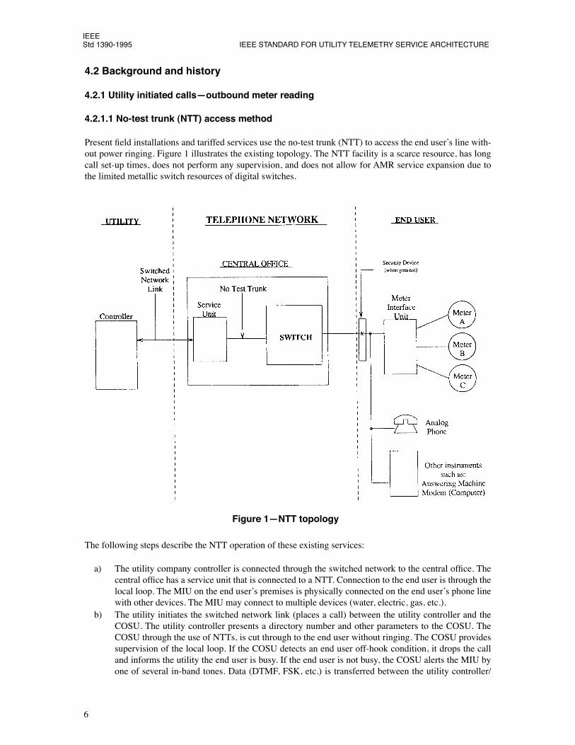
Present Þeld installations and tariffed services use the no-test trunk (NTT) to access the end userÕs line with-out power ringing. Figure 1 illustrates the existing topology. The NTT facility is a scarce resource, has longcall set-up times, does not perform any supervision, and does not allow for AMR service expansion due tothe limited metallic switch resources of digital switches.
The following steps describe the NTT operation of these existing services:
a) The utility company controller is connected through the switched network to the central ofÞce. Thecentral ofÞce has a service unit that is connected to a NTT. Connection to the end user is through thelocal loop. The MIU on the end userÕs premises is physically connected on the end userÕs phone linewith other devices. The MIU may connect to multiple devices (water, electric, gas, etc.).
b) The utility initiates the switched network link (places a call) between the utility controller and theCOSU. The utility controller presents a directory number and other parameters to the COSU. TheCOSU through the use of NTTs, is cut through to the end user without ringing. The COSU providessupervision of the local loop. If the COSU detects an end user off-hook condition, it drops the calland informs the utility the end user is busy. If the end user is not busy, the COSU alerts the MIU byone of several in-band tones. Data (DTMF, FSK, etc.) is transferred between the utility controller/
Figure 1ÑNTT topology
6
IEEEFOR SWITCHED TELEPHONE NETWORK Std 1390-1995
COSU and the MIU. After the telemetry data is sent to the utility controller, the MIU goes to theinactive state, and the COSU informs the switch to release the NTT connection. Another directorynumber and parameters are presented to the COSU by the utility controller. The COSU brings up theNTT again and connects to the local loop for the next meter reading. The NTT is taken down againafter the meter is read. This procedure continues until all directory numbers (meters) have been read.
c) When all meters have been read, the switched network link between the utility controller and theCOSU is disconnected.
The NTT conventions utilize meter reading calls that take place at off peak hours but continue to conßictwith manual and automatic line testing since the same NTT facilities are used. Additionally, since calls aremade on the NTT, longer call set-up/tear-down times are encountered as an increasing number of meters areadded. There is a strong need, when serving additional meter reading services, to reduce the call durationand eliminate the congestion on the NTT.
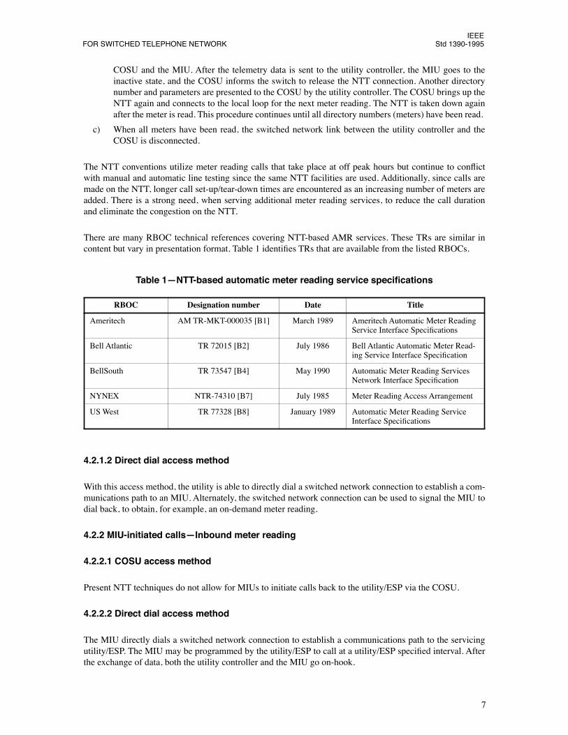
There are many RBOC technical references covering NTT-based AMR services. These TRs are similar incontent but vary in presentation format. Table 1 identiÞes TRs that are available from the listed RBOCs.
4.2.1.2 Direct dial access method
With this access method, the utility is able to directly dial a switched network connection to establish a com-munications path to an MIU. Alternately, the switched network connection can be used to signal the MIU todial back, to obtain, for example, an on-demand meter reading.
4.2.2 MIU-initiated callsÑInbound meter reading
4.2.2.1 COSU access method
Present NTT techniques do not allow for MIUs to initiate calls back to the utility/ESP via the COSU.
4.2.2.2 Direct dial access method
The MIU directly dials a switched network connection to establish a communications path to the servicingutility/ESP. The MIU may be programmed by the utility/ESP to call at a utility/ESP speciÞed interval. Afterthe exchange of data, both the utility controller and the MIU go on-hook.
Table 1ÑNTT-based automatic meter reading service speciÞcations
RBOC Designation number Date Title
Ameritech AM TR-MKT-000035 [B1] March 1989 Ameritech Automatic Meter Reading Service Interface SpeciÞcations
Bell Atlantic TR 72015 [B2] July 1986 Bell Atlantic Automatic Meter Read-ing Service Interface SpeciÞcation
BellSouth TR 73547 [B4] May 1990 Automatic Meter Reading Services Network Interface SpeciÞcation
NYNEX NTR-74310 [B7] July 1985 Meter Reading Access Arrangement
US West TR 77328 [B8] January 1989 Automatic Meter Reading Service Interface SpeciÞcations
7
IEEEStd 1390-1995 IEEE STANDARD FOR UTILITY TELEMETRY SERVICE ARCHITECTURE
5. Utility telemetry service operation and architecture
This clause identiÞes the UTS operation and architecture for telephone network access to and from analogsubscriber loops by describing functional units. The overall functionality results from communicationsbetween the functional units (entities) using information ßows at the interface point. Figure 2 illustrates thefunctional elements of a UTS architecture.
This UTS operation via the telephone network is depicted by a meter reading service. The telemetry serviceis a basic transport service capable of supporting many different communications applications. In actuality,any utility or ESP may provide a service to communicate data to or from the TIU on the end userÕs premise.For example, meter reading or remote diagnosis of appliance applications may be activated by a utility orESP. Conversely, the meter, appliance, or automatic calling device may initiate calls to the utility or ESP.
The telephone end user whose line is being used for UTS is typically not alerted that a utility telemetry callis in process. Also, calling priority is always given to the end user. When the utility or ESP calls the TIU usingthe COSU access method, the end userÕs line is alerted by a signal that does not operate the end user CPE ringer.When the utility or ESP calls the TIU using the direct dial access method, the end userÕs ringer will be operated.Additionally, the TIU must go on-hook (off-hook transmission method) or go to the idle state (on-hook trans-mission method) if the end user goes off-hook (except for security devices). The end user will only becomeaware of the utility/ESP call if dialing or data transmission is heard or a delayed dial tone is detected.
Various components and protocols of the UTS are the subject of further IEEE standards efforts, some ofwhich are presently under development.
5.1 Utility telemetry service network description
The telephone network provides communications connectivity between the utility or the ESP and the TIUsthat are connected to meters, devices, or other end user systems. Telemetry calls may be initiated from eitherthe utility/ESP or the TIU on the end userÕs line. Calls to the utility/ESP may also be connected to telephonecompany provided multi-line hunt groups or automatic call distribution (ACD) services.
In order to completely describe the progress of the telemetry call and the differences between the identiÞednetwork access methods, it is important to describe certain internal telephone network operations. Theseinternal telephone network operations are under control of the local telephone company and are fully deÞnedin the local telephone company technical documents.
Figure 2ÑFunctional elements of the UTS architecture for telephone network communications
8
IEEEFOR SWITCHED TELEPHONE NETWORK Std 1390-1995
5.1.1 Utility access to and from the telephone network
The utility may access the telephone network with a variety of methods. The most common method will beto utilize the public switched telephone network with the utility dialing a connection to the COSU networkelement or directly dialing the TIU. Other communications methods may utilize direct connections to theCOSU network element (hard wired), high-speed digital connections, or a network gateway element.
5.1.2 Network access method
5.1.2.1 COSU access method
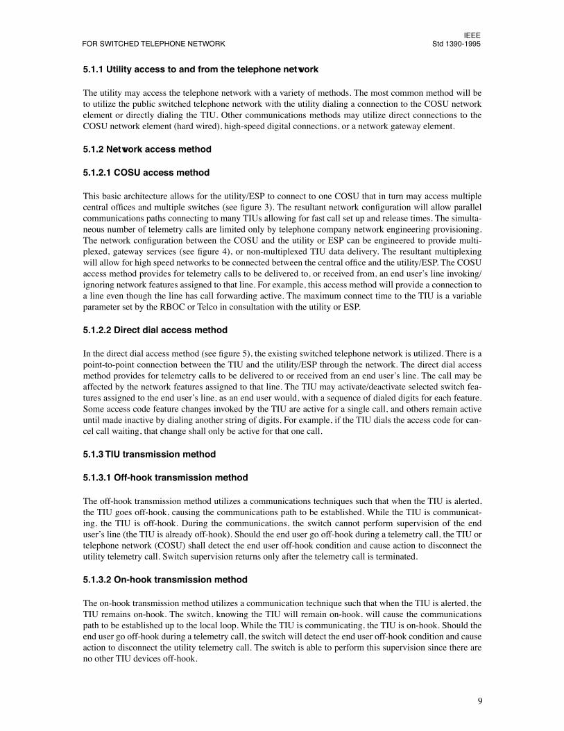
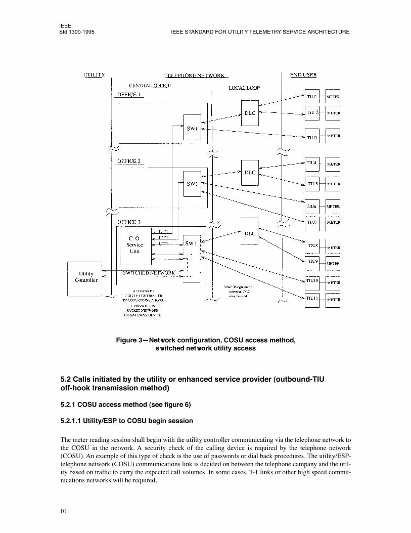
This basic architecture allows for the utility/ESP to connect to one COSU that in turn may access multiplecentral ofÞces and multiple switches (see Þgure 3). The resultant network conÞguration will allow parallelcommunications paths connecting to many TIUs allowing for fast call set up and release times. The simulta-neous number of telemetry calls are limited only by telephone company network engineering provisioning.The network conÞguration between the COSU and the utility or ESP can be engineered to provide multi-plexed, gateway services (see Þgure 4), or non-multiplexed TIU data delivery. The resultant multiplexingwill allow for high speed networks to be connected between the central ofÞce and the utility/ESP. The COSUaccess method provides for telemetry calls to be delivered to, or received from, an end userÕs line invoking/ignoring network features assigned to that line. For example, this access method will provide a connection toa line even though the line has call forwarding active. The maximum connect time to the TIU is a variableparameter set by the RBOC or Telco in consultation with the utility or ESP.
5.1.2.2 Direct dial access method
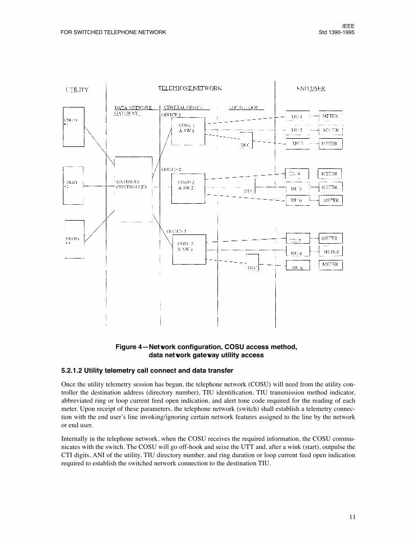
In the direct dial access method (see Þgure 5), the existing switched telephone network is utilized. There is apoint-to-point connection between the TIU and the utility/ESP through the network. The direct dial accessmethod provides for telemetry calls to be delivered to or received from an end userÕs line. The call may beaffected by the network features assigned to that line. The TIU may activate/deactivate selected switch fea-tures assigned to the end userÕs line, as an end user would, with a sequence of dialed digits for each feature.Some access code feature changes invoked by the TIU are active for a single call, and others remain activeuntil made inactive by dialing another string of digits. For example, if the TIU dials the access code for can-cel call waiting, that change shall only be active for that one call.
5.1.3 TIU transmission method
5.1.3.1 Off-hook transmission method
The off-hook transmission method utilizes a communications techniques such that when the TIU is alerted,the TIU goes off-hook, causing the communications path to be established. While the TIU is communicat-ing, the TIU is off-hook. During the communications, the switch cannot perform supervision of the enduserÕs line (the TIU is already off-hook). Should the end user go off-hook during a telemetry call, the TIU ortelephone network (COSU) shall detect the end user off-hook condition and cause action to disconnect theutility telemetry call. Switch supervision returns only after the telemetry call is terminated.
5.1.3.2 On-hook transmission method
The on-hook transmission method utilizes a communication technique such that when the TIU is alerted, theTIU remains on-hook. The switch, knowing the TIU will remain on-hook, will cause the communicationspath to be established up to the local loop. While the TIU is communicating, the TIU is on-hook. Should theend user go off-hook during a telemetry call, the switch will detect the end user off-hook condition and causeaction to disconnect the utility telemetry call. The switch is able to perform this supervision since there areno other TIU devices off-hook.
9
IEEEStd 1390-1995 IEEE STANDARD FOR UTILITY TELEMETRY SERVICE ARCHITECTURE
5.2 Calls initiated by the utility or enhanced service provider (outbound-TIU off-hook transmission method)
5.2.1 COSU access method (see Þgure 6)
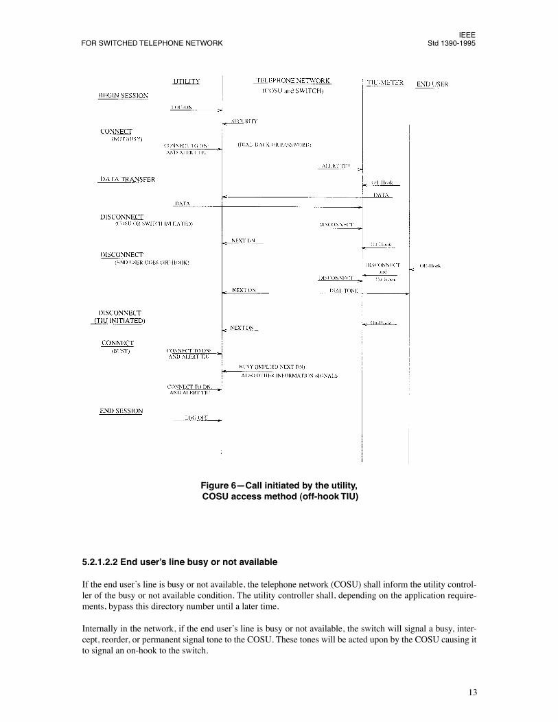
5.2.1.1 Utility/ESP to COSU begin session
The meter reading session shall begin with the utility controller communicating via the telephone network tothe COSU in the network. A security check of the calling device is required by the telephone network(COSU). An example of this type of check is the use of passwords or dial back procedures. The utility/ESP-telephone network (COSU) communications link is decided on between the telephone campany and the util-ity based on trafÞc to carry the expected call volumes. In some cases, T-1 links or other high speed commu-nications networks will be required.
5.2.1.2 Utility telemetry call connect and data transfer
Once the utility telemetry session has begun, the telephone network (COSU) will need from the utility con-troller the destination address (directory number), TIU identiÞcation, TIU transmission method indicator,abbreviated ring or loop current feed open indication, and alert tone code required for the reading of eachmeter. Upon receipt of these parameters, the telephone network (switch) shall establish a telemetry connec-tion with the end userÕs line invoking/ignoring certain network features assigned to the line by the networkor end user.
Internally in the telephone network, when the COSU receives the required information, the COSU commu-nicates with the switch. The COSU will go off-hook and seize the UTT and, after a wink (start), outpulse theCTI digits, ANI of the utility, TIU directory number, and ring duration or loop current feed open indicationrequired to establish the switched network connection to the destination TIU.
IEEEStd 1390-1995 IEEE STANDARD FOR UTILITY TELEMETRY SERVICE ARCHITECTURE
5.2.1.2.1 End userÕs line not busy
If the end userÕs line is not busy, the telephone network establishes a telemetry connection with the TIU. Theend userÕs phone is not rung. The telephone network (COSU) is responsible for alerting the TIU. When theTIU is alerted, it goes off-hook and performs a security check with the telephone network (COSU). If thesecurity check is accepted, the telemetry data transfer stage is entered between the telephone network(COSU) and the TIU. This data transfer stage is transparent to the telephone network (switch). SufÞcientalert tones (or a subaddressing technique) are required to allow for multiple TIUs at a single location or formulti-party service.
Internally in the telephone network, if the line is not busy (trafÞc or maintenance), the switch, if directed,will cause a time slot to be assigned in the DLC equipment and the COSU will be cut through to the enduserÕs line. When a telemetry connection is made with the TIU, the switch signals the COSU causing theTIU to be alerted. When the switch detects an off-hook (TIU) on the line, the switch notiÞes the COSU ofthe off-hook signal. The COSU stops the alert tone and data transfer takes place.
If the end userÕs line is busy or not available, the telephone network (COSU) shall inform the utility control-ler of the busy or not available condition. The utility controller shall, depending on the application require-ments, bypass this directory number until a later time.
Internally in the network, if the end userÕs line is busy or not available, the switch will signal a busy, inter-cept, reorder, or permanent signal tone to the COSU. These tones will be acted upon by the COSU causing itto signal an on-hook to the switch.
Figure 6ÑCall initiated by the utility, COSU access method (off-hook TIU)
13
IEEEStd 1390-1995 IEEE STANDARD FOR UTILITY TELEMETRY SERVICE ARCHITECTURE
5.2.1.3 Utility telemetry call disconnect
After the telemetry data is transmitted to the telephone network (COSU) and utility controller, the TIU shallgo on-hook and become inactive. The TIU shall transmit a disconnect signal (disconnect message or drop ofcarrier) to the telephone network (COSU) or utility controller prior to, or concurrent with, going on-hookand becoming inactive. After the TIU goes on-hook and becomes inactive, the TIU may not immediatelyreseize the end userÕs line. Reseizure rules are deÞned in IEEE P1390.2 (1/96-001).3 The TIU and telephonenetwork (COSU) shall become inactive upon loss of carrier or signal level.
5.2.1.3.1 Disconnect initiated by the utility controller
The utility controller initiates this disconnect by informing the telephone network (COSU) to disconnect thetelemetry call. The telephone network shall disconnect the telemetry call using the telephone network (COSU)disconnect case described in 5.2.1.3.2.
5.2.1.3.2 Disconnect initiated by the telephone network (COSU or switch)
The telephone network (COSU) may receive a disconnect request from the utility controller, the TIU (mes-sage or drop of carrier), or generate the disconnect itself based on internal information. The telephone net-work (COSU) initiates this disconnect by informing the telephone network (switch) to disconnect the call.
Disconnect is initiated by the telephone network (switch) transmitting a forward disconnect (open) of approx-imately 800 ms duration to the TIU as an indicator to the TIU to go on-hook and become inactive. The telephonenetwork takes down the call. The forward disconnect signal is to ensure that all CPE devices clear the line.
The telephone network (switch) may internally release the call independent of any utility controller or TIUaction, requiring recovery conditions to take place in the TIU and the telephone network (COSU). This typeof disconnect may be initiated by telephone network personnel, from interactions with other switch features,or a maximum utility telemetry call time out. The telephone network (COSU) will inform the utility control-ler the call was taken down.
Internally in the telephone network, the COSU initiates this disconnect by giving an on-hook signal to theswitch. The switch transmits a forward disconnect (open) to the TIU. The switch takes down the call and sig-nals an on-hook condition to the COSU at the beginning of the disconnect signal to the TIU.
5.2.1.3.3 Disconnect initiated by the end user going off-hook
The telephone network (switch) cannot detect an end user going off-hook since the TIU is already off-hook.The TIU or the telephone network (COSU), or both, are responsible for detecting the end user off-hook. TheTIU shall send a disconnect signal to the COSU prior to or concurrent with going on-hook. Alternatively, thetelephone network (COSU) may detect the decreased signal level caused by the end user going off-hook. Ineither case, the disconnect takes place as described in the telephone network (COSU) case described in5.2.1.3.2. The telephone network (switch), sensing an off-hook remaining on the line after the 800 ms open,may initiate a new origination and deliver dial tone to the end user in possibly a delayed interval.
5.2.1.3.4 Disconnect initiated by the TIU going on-hook
The telephone network (switch) receives an on-hook signal from the TIU. The telephone network (switch)takes the call down, and the utility controller is notiÞed that the call was taken down.
Internally in the telephone network, the switch senses an on-hook from the line. The switch signals on-hookto the COSU and takes the call down. The COSU informs the utility controller of the disconnect.
3Numbers preceded by P are IEEE authorized standards projects that were not approved by the IEEE Standards Board at the time thispublication went to press. For information about obtaining drafts, contact the IEEE.
14
IEEEFOR SWITCHED TELEPHONE NETWORK Std 1390-1995
5.2.1.4 Utility/ESP to the COSU end session
At some point, the utility/ESP or telephone network (COSU) terminates the communications via the tele-phone network.
5.2.2 Direct dial access method (see Þgure 7)
5.2.2.1 Utility telemetry call connect and data transfer
The utility/ESP dials the directory number of the end user. The telephone network shall establish a telemetryconnection with the end userÕs line utilizing the network features assigned to the line by the network or enduser. A number of different techniques have been implemented to cause the TIU to go off-hook and becomeactive.
Figure 7ÑCall initiated by the utility, direct dial access method (off-hook TIU)
15
IEEEStd 1390-1995 IEEE STANDARD FOR UTILITY TELEMETRY SERVICE ARCHITECTURE
5.2.2.1.1 End userÕs line not busy
If the end userÕs line is not busy, the switched network rings the end userÕs line using standard ringing. Vari-ous techniques are employed to target the call to the TIU. Depending on the technique employed, the TIUeither goes off-hook and answers the call or dials back to the utility/ESP. If a later call-back is required, it isdescribed in 5.3 of this document. Telemetry data is transparent to the telephone network.
5.2.2.1.2 End userÕs line busy or not available
If the end userÕs line is busy or not available, the switch network returns busy (or other tones or announce-ments) to the utility/ESP. The utility/ESP shall go on-hook. Depending on the application requirements, theutility controller will bypass this directory number until a later time.
5.2.2.2 Utility telemetry call disconnect
5.2.2.2.1 Disconnect initiated by the telephone network (switch)
The telephone network (switch) may initiate a disconnect by telephone network personnel or from interac-tions with other features. Both TIU and utility controller shall execute recovery procedures. These recoveryprocedures shall include the TIU and utility controller going on-hook and becoming inactive.
5.2.2.2.2 Disconnect initiated by the utility/ESP
The utility/ESP may initiate a disconnect by going on-hook, which will terminate the switched telephonenetwork call. The TIU shall go on-hook and become inactive.
5.2.2.2.3 Disconnect initiated by the end user going off-hook
The TIU is responsible for detecting the end user going off-hook. The TIU should send a disconnect signalto the utility controller prior to, or simultaneous with, going on-hook and becoming inactive. The utility con-troller goes on-hook, which will terminate the switched telephone network call. The telephone network(switch) sensing an off-hook remaining on the line, initiates a new origination and delivers dial tone to theend user. If the modiÞed calling line disconnect feature is assigned to the line, the telephone network willrequire the line to go on-hook prior to receiving the dial tone.
5.2.2.2.4 Disconnect initiated by the TIU going on-hook
If the TIU goes on-hook and inactive to disconnect the call, and the utility controller remains off-hook, thetelephone network will not disconnect the call due to post disconnect timing. The call will be disconnected atthe end of the post disconnect timing period or when the utility controller goes on-hook, whichever occursÞrst.
5.3 Calls initiated by the TIU (inbound-TIU off-hook transmission method)
5.3.1 Billing for calls initiated by the TIU
With both the COSU access method and direct dial access method, utility telemetry calls would be allowedwhen the line is available for network use or when the end userÕs line is unassigned for billing purposes andreverse charges can be made. In the COSU access method, all calls would be allowed since the telephonenetwork (switch) produces a billing record charging the utility directory number (reverse charging). In thedirect dial access method, only 800 number calls would be allowed by the telephone network if no local billcan be made.
16
IEEEFOR SWITCHED TELEPHONE NETWORK Std 1390-1995
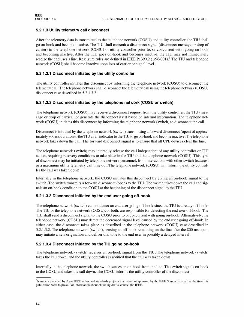
5.3.2 COSU access method (see Þgure 8)
5.3.2.1 Utility telemetry call connect and data transfer
At a particular time, the TIU, after detecting an idle line, goes off-hook and dials an access code. The tele-phone network (switch) recognizes the access code and presents a second dial tone. At the second dial toneor TIU time out, the TIU sends out a string of digits indicating the directory number of the destination tele-phone network COSU and the directory number of the destination utility/ESP. The telephone network(switch) recognizes the telemetry call and allows the call to proceed regardless of the state of the end usernetwork features. The telephone network (COSU) shall perform a security check. If the security check is notaccepted, the telephone network (COSU) immediately disconnects the call. If the security check is accepted,the call is allowed to proceed. This security check is required to verify authorized use of the telemetry ser-vice. If there is no answer from the telephone network (COSU) or the utility, the TIU shall go on-hook andbecome inactive.
5.3.2.1.1 Utility or ESPÕs line not busy
The directory number of the destination utility/ESP identiÞes which utility or ESP is to receive the TIU data.If not connected already, the utility or ESP is alerted and the utility or ESP goes off-hook. Various communi-cations connections and application protocols between the telephone network (COSU) and the utility con-troller will create a communications path for either a point to point connection or for multiplexing TIU callson a single utility controller connection (multiple sessions). Data transfer may ßow in both directions and istransparent to the telephone network.
5.3.2.1.2 Utility or ESPÕs line or telephone network (COSU) busy
If the telephone network (COSU) destination directory number is busy or not available, the telephone net-work (switch) will indicate busy or other tones to the TIU. The TIU immediately goes on-hook and becomesInactive. If the utility/ESP destination is busy, the telephone network (COSU) signals the TIU that the utility/ESP is busy and signals the telephone network (switch) to release the call and the network features are againmade available for the end user. The TIU goes on-hook and becomes inactive. Depending on the applicationprotocols, if the utility controller was busy, the telephone network (COSU) may automatically reinitiate theutility/TIU connection at a later time or the TIU may redial the call again.
5.3.2.2 Utility telemetry call disconnect
After the telemetry data is transmitted, the TIU shall go on-hook and become inactive. The call is releasedand the network features are again made available for the end user. Immediate reseizure of the line by theTIU after going on-hook and becoming inactive is not allowed. This application dependent reseizure require-ment will allow the end user to initiate a call(s) prior to TIU line reseizure [i.e., emergency (911) calls].These requirements are deÞned in IEEE P1390.2. The TIU, telephone network (COSU), and utility control-ler shall go on-hook and become Inactive on loss of carrier.
Security-type automatic calling devices are an exception to the call terminating and reseizure rules. It is stan-dard industry practice to place all security devices between all CPE and the network interface. When there isa security alarm, the alarm device cuts off all CPE from the line.
5.3.2.2.1 Disconnect initiated by the utility controller/ ESP
The utility controller initiates this disconnect by informing the telephone network (COSU) to disconnect thetelemetry call. The telephone network shall disconnect the telemetry call using the telephone network(COSU) disconnect case described in 5.3.2.2.2.
17
IEEEStd 1390-1995 IEEE STANDARD FOR UTILITY TELEMETRY SERVICE ARCHITECTURE
5.3.2.2.2 Disconnect initiated by the telephone network (COSU or switch)
The telephone network (COSU) may receive a disconnect request from the utility controller or generate thedisconnect itself based on internal information. The telephone network (COSU) initiates this disconnect byinforming the telephone network (switch) to disconnect the call.
The telephone network (switch) initiates this disconnect by transmitting a forward disconnect (open) of800 ms duration to the TIU, which shall go on-hook and become inactive.
Figure 8ÑCall initiated by the TIU, COSU access method (off-hook TIU)
18
IEEEFOR SWITCHED TELEPHONE NETWORK Std 1390-1995
The telephone network (switch) may internally release the call independent of any utility controller or TIUaction, requiring recovery conditions to take place in the TIU and telephone network (COSU). This type ofdisconnect may be initiated by telephone company personnel or interactions with other switch features. Thetelephone network (COSU) will inform the utility controller the call was taken down.
Internally in the telephone network, the COSU initiates this disconnect by giving an on-hook signal to theswitch. The switch transmits a forward disconnect (open) to the TIU. The switch takes down the call and sig-nals an on-hook to the COSU at the beginning of the disconnect signal to the TIU.
5.3.2.2.3 Disconnect initiated by the end user going off-hook
The telephone network (switch) cannot detect an end user going off-hook since the TIU is already off-hook.The TIU or the telephone network (COSU), or both, are responsible for detecting the end user off-hook. TheTIU should send a disconnect signal to the telephone network (COSU) prior to, or simultaneous with, goingon-hook. Alternatively, the telephone network (COSU) may detect the decreased signal level caused by theend user going off-hook. In either case, the disconnect takes place as described in the telephone network(COSU) case described in 5.3.2.2.2. The telephone network (switch), sensing an off-hook remaining on theline after the 800 ms open, initiates a new origination and delivers dial tone to the end user in a possiblydelayed interval.
Figure 8 (ConÕt.)ÑCall initiated by the TIU, COSU access method (off-hook TIU)
19
IEEEStd 1390-1995 IEEE STANDARD FOR UTILITY TELEMETRY SERVICE ARCHITECTURE
Internally in the telephone network, the COSU initiates this disconnect by signaling on-hook to the switch.The disconnect takes place as deÞned in the COSU disconnect case described in 5.3.2.2.2.
5.3.2.2.4 Disconnect initiated by the TIU going on-hook
The telephone network (switch) receives an on-hook signal from the TIU. The telephone network (switch)takes the call down and the utility controller is notiÞed the call was taken down.
Internally in the telephone network, the switch senses an on-hook from the line. The switch signals on-hookto the COSU and takes the call down. The COSU informs the utility controller of the disconnect.
5.3.3 Direct dial access method (see Þgure 9)
5.3.3.1 Utility telemetry call connect and data transfer
The TIU, after detecting an idle line, goes off-hook and dials a string of digits indicating to the telephonenetwork (switch) the directory number of the destination utility or the ESP. The string of digits may includeend-user activated access codes which may activate/deactivate end user network features.
5.3.3.1.1 Utility or ESPÕs line not busy
If the utility or the ESPÕs line is not busy, the telephone network (switch) connects the call and rings thedirectory number of the destination utility/ESP using standard ringing. The utility controller signals off-hookresulting in a point-to-point connection. Data transfer may ßow in both directions and is transparent to thetelephone network.
5.3.3.1.2 Utility or ESPÕs line busy
If the utility/ESP directory number is busy or not available, the switch shall indicate busy (or other tones orannouncements) to the TIU. The TIU immediately signals on-hook and becomes inactive. The TIU may,depending on the application requirements, redial this directory number at a later time.
5.3.3.2 Utility telemetry call disconnect
After the telemetry data is transmitted, the TIU shall go on-hook and become inactive. Immediate reseizureof the line by the TIU after going on-hook and becoming inactive is not allowed. This application dependentreseizure requirement will allow the end user to initiate a call(s) prior to TIU line reseizure [i.e., emergency(911) calls]. These requirements are deÞned in IEEE P1390.2. The TIU, telephone network (COSU), andutility controller shall go on-hook and become inactive on loss of carrier.
Security-type automatic calling devices are an exception to the call terminating and reseizure rules. It is stan-dard industry practice to place all security devices between all CPE and the network interface. When there isa security alarm, the alarm device cuts off all CPE from the line.
When the call is released, the telephone network (switch) will return per call type, TIU access code featurechanges to their previous state if they are deÞned for one call. TIU access code feature changes deÞned formultiple calls will not be automatically changed. These feature changes can only be changed by reinitiatingdial tone and dialing the appropriate access code.
20
IEEEFOR SWITCHED TELEPHONE NETWORK Std 1390-1995
5.3.3.2.1 Disconnect initiated by the utility or ESP
The utility or ESP signals on-hook to the network. If the TIU remains off-hook (active), the network will dis-connect the telemetry call after post-disconnect timing has expired. If the TIU goes on-hook and becomesinactive, the call is disconnected immediately.
5.3.3.2.2 Disconnect initiated by the telephone network (switch)
A disconnect may be initiated by the telephone network (switch). For example, this type of disconnect maybe initiated by telephone company personnel. Both TIU and utility controller shall execute recovery proce-dures. These recovery procedures shall include the TIU and utility controller going on-hook and becominginactive.
Figure 9ÑCall initiated by the TIU, direct dial access method
21
IEEEStd 1390-1995 IEEE STANDARD FOR UTILITY TELEMETRY SERVICE ARCHITECTURE
5.3.3.2.3 Disconnect initiated by the end user going off-hook
The TIU and/or the utility controller shall detect the end user going off-hook. The TIU shall inform the util-ity controller (data signal or changed signal level) of the end user off-hook condition.
The TIU shall go on-hook and become inactive. The utility controller or ESP shall go on-hook for the telem-etry call to be released. The telephone network will not disconnect the call due to post-disconnect timingwhen the utility/ESP goes on-hook. The end user will receive dial tone after the post disconnect timing inter-val. If the utility/ESP does not go on-hook, the end user will not receive dial tone unless the end userÕs linegoes on-hook. This is normal telephone network operating conditions. Also, if the modiÞed calling line dis-connect feature is assigned to the line, the telephone network requires the line to go on-hook prior to receiv-ing dial tone.
5.3.3.2.4 Disconnect initiated by the TIU
The TIU initiates the disconnect by going on-hook and becoming inactive. The telephone network (switch)disconnects the call. The utility controller goes on-hook.
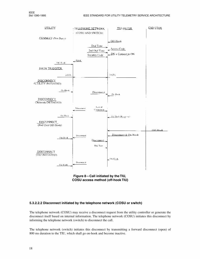
5.4 Calls initiated by the utility or enhanced service provider (outbound-TIU on-hook transmission method)
5.4.1 COSU access method (see Þgure 10)
5.4.1.1 Utility/ESP to COSU begin session
The meter reading session shall begin with the utility controller communicating via the telephone network tothe COSU in the network. A security check of the calling device is required by the telephone network(COSU). An example of this type of check is the use of passwords or dial back procedures. The utility/ESP-telephone network (COSU) communications link is telephone company engineered to carry the expectedcall volumes. In some cases, T-1 links or other high speed communications networks will be required.
5.4.1.2 Utility telemetry call connect and data transfer
Once the utility telemetry session has begun, the telephone network (COSU) will need from the utility con-troller the destination address (i.e., directory number), TIU identiÞcation, TIU transmission method indica-tor, abbreviated ring or loop current feed open indication, and the alert tone code required for the reading ofeach meter. Upon receipt of these parameters, the telephone network shall establish a telemetry connectionwith the end userÕs line regardless of the state of the network features assigned to the line by the network orend user.
Internally in the telephone network, when the COSU receives the required information, the COSU commu-nicates with the switch. The COSU will go off-hook and seize the utility telemetry trunk and, after a wink(start), outpulse the CTI digits, ANI, directory number, and ring duration or loop current feed open indica-tion required to establish the switched network connection to the destination TIU.
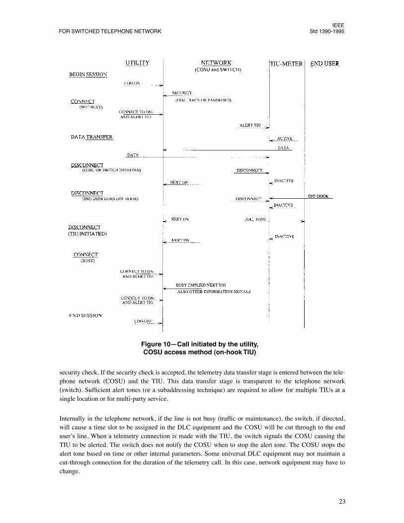
5.4.1.2.1 End userÕs line not busy
If the end userÕs line is not busy, the telephone network establishes a telemetry connection with the TIU. Theend userÕs phone is not rung. The telephone network (COSU) is responsible for alerting the TIU. When theTIU is alerted, it remains on-hook but becomes active. The TIU and telephone network (COSU) perform a
22
IEEEFOR SWITCHED TELEPHONE NETWORK Std 1390-1995
security check. If the security check is accepted, the telemetry data transfer stage is entered between the tele-phone network (COSU) and the TIU. This data transfer stage is transparent to the telephone network(switch). SufÞcient alert tones (or a subaddressing technique) are required to allow for multiple TIUs at asingle location or for multi-party service.
Internally in the telephone network, if the line is not busy (trafÞc or maintenance), the switch, if directed,will cause a time slot to be assigned in the DLC equipment and the COSU will be cut through to the enduserÕs line. When a telemetry connection is made with the TIU, the switch signals the COSU causing theTIU to be alerted. The switch does not notify the COSU when to stop the alert tone. The COSU stops thealert tone based on time or other internal parameters. Some universal DLC equipment may not maintain acut-through connection for the duration of the telemetry call. In this case, network equipment may have tochange.
Figure 10ÑCall initiated by the utility, COSU access method (on-hook TIU)
23
IEEEStd 1390-1995 IEEE STANDARD FOR UTILITY TELEMETRY SERVICE ARCHITECTURE
5.4.1.2.2 End userÕs line busy or not available
If the end userÕs line is busy or not available, the telephone network (COSU) shall inform the utility control-ler of the busy or not available condition. The utility controller shall, depending on the application require-ments, bypass this directory number until a later time.
Internally in the network, if the end userÕs line is busy or not available, the switch will signal a busy, inter-cept, reorder, or permanent signal tone (per the LSSGR) to the COSU. These tones will be acted upon by theCOSU causing it to signal an on-hook to the switch.
5.4.1.3 Utility telemetry call disconnect
After the telemetry data is transmitted to the telephone network (COSU) and utility controller, the TIU shallbecome inactive. The TIU shall transmit a disconnect signal (disconnect message or drop of carrier) to thetelephone network (COSU) or utility controller prior to, or concurrent with, becoming inactive. After theTIU becomes inactive, the TIU may not immediately reseize the end userÕs line. Reseizure rules are deÞnedin IEEE P1390.2. The TIU and telephone network (COSU) shall become inactive upon loss of carrier or sig-nal level.
5.4.1.3.1 Disconnect initiated by the utility controller
The utility controller shall initiate this disconnect by informing the telephone network (COSU) to disconnectthe telemetry call. The telephone network shall disconnect the telemetry call using the telephone network(COSU) disconnect case described in 5.4.1.3.2.
5.4.1.3.2 Disconnect initiated by the telephone network (COSU or switch)
The telephone network (COSU) may receive a disconnect request from the utility controller, the TIU (mes-sage or drop of carrier), or generate the disconnect itself based on internal information. The telephone net-work (COSU) initiates this disconnect by informing the telephone network (switch) to disconnect the call.
The telephone network (switch) shall initiate this disconnect by transmitting a forward disconnect (open) ofapproximately 800 ms duration to the TIU, which shall become inactive. The telephone network takes downthe call. The forward disconnect signal is to ensure that all CPE devices clear the line.
The telephone network (switch) may internally release the call independent of any utility controller or TIUaction, requiring recovery conditions to take place in the TIU and telephone network (COSU). This type ofdisconnect may be initiated by telephone network personnel, from interactions with other switch features, ora maximum utility telemetry call time-out. The telephone network (COSU) will inform the utility controllerthe call was taken down.
Internally in the telephone network, the COSU initiates this disconnect by giving an on-hook signal to theswitch. The switch transmits a forward disconnect (open) to the TIU. The switch takes down the call and sig-nals an on-hook condition to the COSU at the beginning of the disconnect signal to the TIU.
5.4.1.3.3 Disconnect initiated by the end user going off-hook
The telephone network (switch) will detect an end user going off-hook since the TIU is not off-hook. Thedisconnect is initiated by the telephone network (switch) case as described above. The telephone network(switch), sensing an off-hook remaining on the line after the 800 ms open, initiates a new origination anddelivers dial tone to the end user. The telephone network (COSU) notiÞes the utility controller the call wastaken down.
24
IEEEFOR SWITCHED TELEPHONE NETWORK Std 1390-1995
5.4.1.3.4 Disconnect initiated by the TIU going inactive
The telephone network (switch) cannot detect the TIU going inactive since it is already on-hook. The TIUshould send a disconnect signal to the telephone network (COSU) prior to going inactive. Alternatively, thetelephone network (COSU) may detect a decreased or lack of signal level from the TIU going inactive. Ineither case, the telephone network (COSU) is responsible for initiating the disconnect of the telemetry call.The telephone network (switch) takes down the telemetry call. The telephone network (COSU) informs theutility controller the call was taken down.
Internally in the network, the COSU initiates this disconnect by signaling on-hook to the switch. The switchdoes not does not transmit an 800 ms open on the line. The switch takes down the call and signals on-hook tothe COSU.
5.4.1.4 Utility/ESP to COSU end session
At some point, the utility/ESP or telephone network (COSU) terminates the communications via thetelephone network.
25
IEEEStd 1390-1995 IEEE STANDARD FOR UTILITY TELEMETRY SERVICE ARCHITECTURE
Annex A
(informative)
Bibliography
[B1] Ameritech, AM TR-MKT-000035, Ameritech Automatic Meter Reading Service Interface SpeciÞca-tions, March 1989.
[B2] Bell Atlantic, TR 72015, Bell Atlantic Automatic Meter Reading Service Interface SpeciÞcation,July 1986.
[B3] Bellcore, TR 00057, issue 2, Jan. 1993.
[B4] BellSouth, TR 73547, Automatic Meter Reading Services Network Interface SpeciÞcation, May 1990.
[B5] FCC Rules and Regulations, ÒRules for Registration of Telephone Equipment,Ó Part 68.
[B6] ÒLATA Switching Systems Generic Requirements (LSSGR),Ó Bell Communications Research(Bellcore).
[B7] NYNEX, NTR-74310, Meter Reading Access Arrangement, July 1985.
[B8] US West, TR 77328, Automatic Meter Reading Service Interface SpeciÞcations, Jan. 1989.