arXiv:1310.1679v1 [cs.NI] 7 Oct 2013 IEEE TRANSACTIONS ON COMMUNICATIONS, VOL. X, NO. X, OCTOBER 2013 1 Stability and Delay Analysis of EPON Registration Protocol Qingpei Cui, Tong Ye, Member, IEEE, Tony T. Lee, Fellow, IEEE, Wei Guo, Member, IEEE and Weisheng Hu, Member, IEEE Abstract—The Ethernet passive optical network (EPON) has recently emerged as the mainstream of broadband access net- works. The registration process of EPON, defined by the IEEE 802.3av standard, is a multi-point control protocol (MPCP) within the media access control (MAC) layer. As with other contention-based channel access methods, such as ALOHA and CSMA, stability and delay are critical issues concerning the performances of implementing the protocol on systems with finite channel capacity. In this paper, the registration process of an EPON subscriber, called optical network units (ONUs), is modeled as a discrete-time Markov chain, from which we derive the fundamental throughput equation of EPON that characterizes the registration processes. The solutions of this characteristic equation depend on the maximum waiting time. The aim of our stability analysis is to pinpoint the region of the maximum waiting time that can guarantee a stable registration throughput and a bounded registration delay. For a maximum waiting time selected from the stable region, we obtain the expression of registration delay experienced by an ONU attempting to register. All analytic results presented in this paper were verified by simulations. Index Terms—EPON, registration process, IEEE 802.3av, sta- ble region, registration delay. I. I NTRODUCTION D ESPITE the growth of Internet traffic and the telecommu- nications backbone at an unprecedented pace, the access network between end-users and the core network remains the bottleneck for broadband integrated services. The Ethernet passive optical network (EPON) has recently emerged as one of the most promising candidates for broadband access networks. Combining Ethernet technologies and optical fiber infrastructures, the EPON is simple, cost-effective, and capable of supporting various kinds of bandwidth-intensive services, such as video-on-demand (VoD), distance learning, and video conferencing [1]. Currently, this widespread technology for fiber-to-the-home (FTTH) applications has become the main- stream of the broadband access market [2]–[5]. The EPON is a point-to-multipoint network, as illustrated in Fig. 1, which consists of an optical line terminal (OLT) at the central office, N optical network units (ONU) at the subscriber side, and a 1: N optical coupler (OC) in between. The population of ONUs N is currently 32 or 64, and will extend to 256 or even 512 to meet the ever-increasing demands This work was supported by the National Science Foundation of China under Grants 61271215, 61001074, 61172065, 61071080, and 60825103, in part by Qualcomm Corporation Foundation, in part by the 973 program (2010CB328205, 2010CB328204), and in part by Shanghai 09XD1402200. The authors are with the State Key Laboratory of Advanced Optical Com- munication Systems and Networks, Shanghai Jiao Tong University, Shanghai 200030, China (e-mail: {cuiqingpei, yetong, ttlee, wguo, wshu}@sjtu.edu.cn. OLT ONU 1 ONU 2 ONU N OC ONU N-1 Q Fig. 1. Illustration of the EPON network. of FTTH applications [6]–[8]. Based on an online scheduling of the OLT, the ONUs share the bandwidth of the channel between the OLT and the OC in a time-division-multiplexing (TDM) manner. Thus, the OLT should have information about all active ONUs in advance. The registration process is a protocol defined by the IEEE 802.3av standard [9] that permits the OLT to collect infor- mation about those offline ONUs that request access to the network. The OLT initiates a discovery window for each regis- tration process. In the discovery window, all registered online ONUs stop their upstream transmissions, while unregistered ONUs can randomly send the registration requests to the OLT if they want to be connected. As a result, the registration request of an ONU could be ruined if it collides with other randomly generated requests in the discovery window. The failed ONUs tries again by sending registration requests in the next discovery window [1], [10]. The collisions among registration requests reduce the success probability or the throughput of the registration process [1], [11]. In the registration protocol defined in the IEEE 802.3av standard, the maximum waiting time [12] is the only adjustable parameter in the practical operation of the network. If the max- imum waiting time is set too short, excessive collisions may lead to many reattempts accumulated by unsuccessful ONUs in the registration processes. Especially in the scenario of FTTH, a large number of ONUs are geometrically clustered in a small residential area [13], as shown in Fig. 1, and each ONU may frequently turn on and off for the sake of power savings. In this case, the system may become unstable and a bounded registration delay cannot be guaranteed for each ONU. On the other hand, expanding the maximum waiting time of the registration process inevitably reduces the bandwidth available for the upstream transmission of normal access service. It is therefore essential to investigate the stability and delay of the registration protocol. Some of the work that focused on the throughput analysis of the EPON registration protocol was
Transcript
arX
iv:1
310.
1679
v1 [
cs.N
I] 7
Oct
201
3IEEE TRANSACTIONS ON COMMUNICATIONS, VOL. X, NO. X, OCTOBER2013 1
Stability and Delay Analysis of EPON RegistrationProtocol
Abstract—The Ethernet passive optical network (EPON) hasrecently emerged as the mainstream of broadband access net-works. The registration process of EPON, defined by the IEEE802.3av standard, is a multi-point control protocol (MPCP)within the media access control (MAC) layer. As with othercontention-based channel access methods, such as ALOHA andCSMA, stability and delay are critical issues concerning theperformances of implementing the protocol on systems withfinite channel capacity. In this paper, the registration processof an EPON subscriber, called optical network units (ONUs),ismodeled as a discrete-time Markov chain, from which we derivethe fundamental throughput equation of EPON that characterizesthe registration processes. The solutions of this characteristicequation depend on the maximum waiting time. The aim of ourstability analysis is to pinpoint the region of the maximum waitingtime that can guarantee a stable registration throughput and abounded registration delay. For a maximum waiting time selectedfrom the stable region, we obtain the expression of registrationdelay experienced by an ONU attempting to register. All analyticresults presented in this paper were verified by simulations.
Index Terms—EPON, registration process, IEEE 802.3av, sta-ble region, registration delay.
I. I NTRODUCTION
DESPITE the growth of Internet traffic and the telecommu-nications backbone at an unprecedented pace, the access
network between end-users and the core network remains thebottleneck for broadband integrated services. The Ethernetpassive optical network (EPON) has recently emerged asone of the most promising candidates for broadband accessnetworks. Combining Ethernet technologies and optical fiberinfrastructures, the EPON is simple, cost-effective, and capableof supporting various kinds of bandwidth-intensive services,such as video-on-demand (VoD), distance learning, and videoconferencing [1]. Currently, this widespread technology forfiber-to-the-home (FTTH) applications has become the main-stream of the broadband access market [2]–[5].
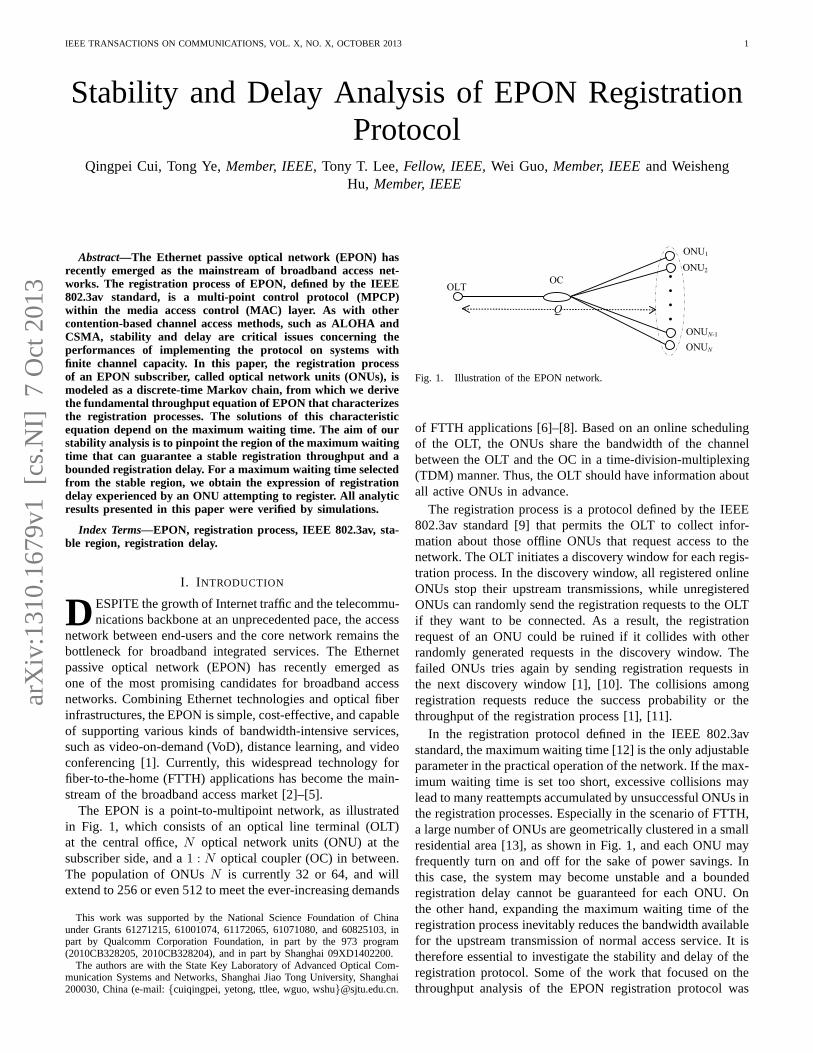
The EPON is a point-to-multipoint network, as illustratedin Fig. 1, which consists of an optical line terminal (OLT)at the central office,N optical network units (ONU) at thesubscriber side, and a1 : N optical coupler (OC) in between.The population of ONUsN is currently 32 or 64, and willextend to 256 or even 512 to meet the ever-increasing demands
This work was supported by the National Science Foundation of Chinaunder Grants 61271215, 61001074, 61172065, 61071080, and 60825103, inpart by Qualcomm Corporation Foundation, in part by the 973 program(2010CB328205, 2010CB328204), and in part by Shanghai 09XD1402200.
The authors are with the State Key Laboratory of Advanced Optical Com-munication Systems and Networks, Shanghai Jiao Tong University, Shanghai200030, China (e-mail:{cuiqingpei, yetong, ttlee, wguo, wshu}@sjtu.edu.cn.
OLT
ONU1
ONU2
ONUN
OC
ONUN-1
Q
Fig. 1. Illustration of the EPON network.
of FTTH applications [6]–[8]. Based on an online schedulingof the OLT, the ONUs share the bandwidth of the channelbetween the OLT and the OC in a time-division-multiplexing(TDM) manner. Thus, the OLT should have information aboutall active ONUs in advance.
The registration process is a protocol defined by the IEEE802.3av standard [9] that permits the OLT to collect infor-mation about those offline ONUs that request access to thenetwork. The OLT initiates a discovery window for each regis-tration process. In the discovery window, all registered onlineONUs stop their upstream transmissions, while unregisteredONUs can randomly send the registration requests to the OLTif they want to be connected. As a result, the registrationrequest of an ONU could be ruined if it collides with otherrandomly generated requests in the discovery window. Thefailed ONUs tries again by sending registration requests inthe next discovery window [1], [10]. The collisions amongregistration requests reduce the success probability or thethroughput of the registration process [1], [11].
In the registration protocol defined in the IEEE 802.3avstandard, the maximum waiting time [12] is the only adjustableparameter in the practical operation of the network. If the max-imum waiting time is set too short, excessive collisions maylead to many reattempts accumulated by unsuccessful ONUs inthe registration processes. Especially in the scenario of FTTH,a large number of ONUs are geometrically clustered in a smallresidential area [13], as shown in Fig. 1, and each ONU mayfrequently turn on and off for the sake of power savings. Inthis case, the system may become unstable and a boundedregistration delay cannot be guaranteed for each ONU. Onthe other hand, expanding the maximum waiting time of theregistration process inevitably reduces the bandwidth availablefor the upstream transmission of normal access service. It istherefore essential to investigate the stability and delayof theregistration protocol. Some of the work that focused on thethroughput analysis of the EPON registration protocol was
IEEE TRANSACTIONS ON COMMUNICATIONS, VOL. X, NO. X, OCTOBER2013 2
T D T D T…… ……
tn-1 tn
T
time
REQ. b
OLT
Registered ONU
Unregistered ONUb
time
time
Power-off ONU
REQ. b
Random delay b
Discovery Slot D=ω+L time
Discovery Window M=2Q+D
L
time
(a)
(b)
REQ. aUnregistered ONUa
time
Random delay a
REQ. a
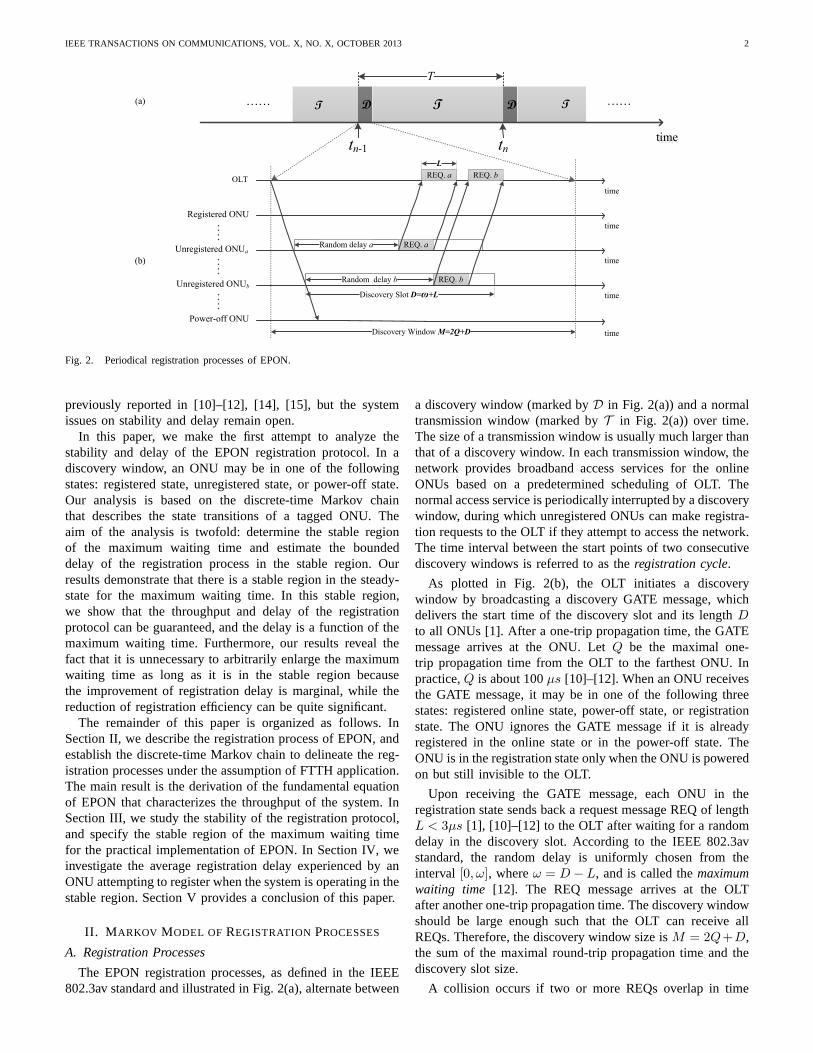
Fig. 2. Periodical registration processes of EPON.
previously reported in [10]–[12], [14], [15], but the systemissues on stability and delay remain open.
In this paper, we make the first attempt to analyze thestability and delay of the EPON registration protocol. In adiscovery window, an ONU may be in one of the followingstates: registered state, unregistered state, or power-off state.Our analysis is based on the discrete-time Markov chainthat describes the state transitions of a tagged ONU. Theaim of the analysis is twofold: determine the stable regionof the maximum waiting time and estimate the boundeddelay of the registration process in the stable region. Ourresults demonstrate that there is a stable region in the steady-state for the maximum waiting time. In this stable region,we show that the throughput and delay of the registrationprotocol can be guaranteed, and the delay is a function of themaximum waiting time. Furthermore, our results reveal thefact that it is unnecessary to arbitrarily enlarge the maximumwaiting time as long as it is in the stable region becausethe improvement of registration delay is marginal, while thereduction of registration efficiency can be quite significant.
The remainder of this paper is organized as follows. InSection II, we describe the registration process of EPON, andestablish the discrete-time Markov chain to delineate the reg-istration processes under the assumption of FTTH application.The main result is the derivation of the fundamental equationof EPON that characterizes the throughput of the system. InSection III, we study the stability of the registration protocol,and specify the stable region of the maximum waiting timefor the practical implementation of EPON. In Section IV, weinvestigate the average registration delay experienced byanONU attempting to register when the system is operating in thestable region. Section V provides a conclusion of this paper.
II. M ARKOV MODEL OF REGISTRATION PROCESSES
A. Registration Processes
The EPON registration processes, as defined in the IEEE802.3av standard and illustrated in Fig. 2(a), alternate between
a discovery window (marked byD in Fig. 2(a)) and a normaltransmission window (marked byT in Fig. 2(a)) over time.The size of a transmission window is usually much larger thanthat of a discovery window. In each transmission window, thenetwork provides broadband access services for the onlineONUs based on a predetermined scheduling of OLT. Thenormal access service is periodically interrupted by a discoverywindow, during which unregistered ONUs can make registra-tion requests to the OLT if they attempt to access the network.The time interval between the start points of two consecutivediscovery windows is referred to as theregistration cycle.
As plotted in Fig. 2(b), the OLT initiates a discoverywindow by broadcasting a discovery GATE message, whichdelivers the start time of the discovery slot and its lengthDto all ONUs [1]. After a one-trip propagation time, the GATEmessage arrives at the ONU. LetQ be the maximal one-trip propagation time from the OLT to the farthest ONU. Inpractice,Q is about 100µs [10]–[12]. When an ONU receivesthe GATE message, it may be in one of the following threestates: registered online state, power-off state, or registrationstate. The ONU ignores the GATE message if it is alreadyregistered in the online state or in the power-off state. TheONU is in the registration state only when the ONU is poweredon but still invisible to the OLT.
Upon receiving the GATE message, each ONU in theregistration state sends back a request message REQ of lengthL < 3µs [1], [10]–[12] to the OLT after waiting for a randomdelay in the discovery slot. According to the IEEE 802.3avstandard, the random delay is uniformly chosen from theinterval [0, ω], whereω = D− L, and is called themaximumwaiting time [12]. The REQ message arrives at the OLTafter another one-trip propagation time. The discovery windowshould be large enough such that the OLT can receive allREQs. Therefore, the discovery window size isM = 2Q+D,the sum of the maximal round-trip propagation time and thediscovery slot size.
A collision occurs if two or more REQs overlap in time
IEEE TRANSACTIONS ON COMMUNICATIONS, VOL. X, NO. X, OCTOBER2013 3
when they arrive at the OLT. All REQs involved in thecollision are ruined and the corresponding registrations arevoid. The ONU that fails to register remains invisible tothe OLT, and it tries to register again in the next discoverywindow. According to the registration process defined in theIEEE 802.3av standard, a discrete-time Markov chain thatcharacterizes the state transitions of a tagged ONU is describedin the rest of this section.
B. Discrete-time Markov Chain
The registration processes described above can be modeledas a discrete-time Markov chain. The application of the EPONsystem under consideration is FTTH, which is regarded as themainstream of broadband access networks [1], [16]. In thescenario of FTTH, it is estimated that the number of ONUsin an EPON can reach as many as 512 in the near future[7], [8]. These ONUs are usually clustered in a small housingdistrict [13], such that their distances to the OLT are almostthe same. In addition, each ONU may frequently turn on andoff to save power. Considering these points, the Markov chainis established under the following assumptions:
1) The ONUs are clustered in a small area, and the propaga-tion delay from each ONU to the OLT is a small constantthat our analysis ignores;
2) The behaviors of ONUs are statistically identical insteady state, and each unregistered ONU makes an in-dependent registration request in a discovery window;
3) The online holding time of each registered ONU, denotedby tA, is a negative exponential random variable withmeanτA = E[tA];
4) The power-off holding time of each idle ONU, denotedby tF , is also a negative exponential random variable withmeanτF = E[tF ];
5) The registration cycle timeT between the starting pointsof two consecutive discovery windows, as illustrated inFig. 2(a), is assumed to be a constant.
The parameters employed in our stability and delay analysisare listed as follows for easy reference:N : population of ONUs in the EPON;ω: maximum waiting time of the discovery window;L: length of a registration request REQ message;G: aggregate traffic in a discovery window, defined as
the average number of ONUs in stateR at thebeginning of a discovery window;
d: registration delay of each ONU when the system isstable;
h: attempt probability, the probability that an ONU notin the registration state will attempt to register in thenext discovery window;
psuc: probability that an ONU attempting to register suc-ceeds in a discovery window;
λout: registration throughput per registration cycle in thestationary state.
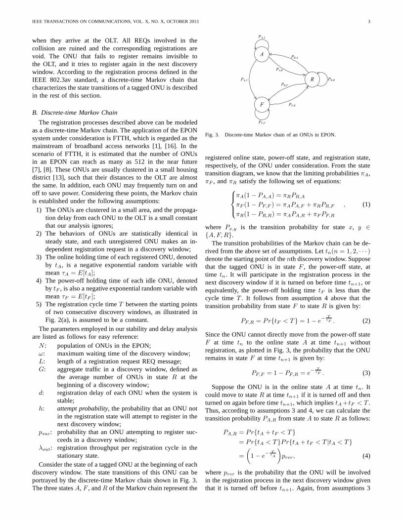
Consider the state of a tagged ONU at the beginning of eachdiscovery window. The state transitions of this ONU can beportrayed by the discrete-time Markov chain shown in Fig. 3.The three statesA, F , andR of the Markov chain represent the
F
R
PR,A
PF,R
PA,F
A
PA,A
PF,F
PR,R
PA,R
PR,F
Fig. 3. Discrete-time Markov chain of an ONUs in EPON.
registered online state, power-off state, and registration state,respectively, of the ONU under consideration. From the statetransition diagram, we know that the limiting probabilitiesπA,πF , andπR satisfy the following set of equations:
πA(1− PA,A) = πRPR,A
πF (1− PF,F ) = πAPA,F + πRPR,F
πR(1 − PR,R) = πAPA,R + πFPF,R
, (1)
where Px,y is the transition probability for statex, y ∈{A,F,R}.
The transition probabilities of the Markov chain can be de-rived from the above set of assumptions. Lettn(n = 1, 2, · · · )denote the starting point of thenth discovery window. Supposethat the tagged ONU is in stateF , the power-off state, attime tn. It will participate in the registration process in thenext discovery window if it is turned on before timetn+1, orequivalently, the power-off holding timetF is less than thecycle time T . It follows from assumption 4 above that thetransition probability from stateF to stateR is given by:
PF,R = Pr{tF < T } = 1− e−
T
τF . (2)
Since the ONU cannot directly move from the power-off stateF at time tn to the online stateA at time tn+1 withoutregistration, as plotted in Fig. 3, the probability that theONUremains in stateF at time tn+1 is given by:
PF,F = 1− PF,R = e−
T
τF . (3)
Suppose the ONU is in the online stateA at time tn. Itcould move to stateR at timetn+1 if it is turned off and thenturned on again before timetn+1, which impliestA+tF < T .Thus, according to assumptions 3 and 4, we can calculate thetransition probabilityPA,R from stateA to stateR as follows:
PA,R = Pr{tA + tF < T }
= Pr{tA < T }Pr{tA + tF < T |tA < T }
=
(
1− e−
T
τA
)
prer, (4)
whereprer is the probability that the ONU will be involvedin the registration process in the next discovery window giventhat it is turned off beforetn+1. Again, from assumptions 3
IEEE TRANSACTIONS ON COMMUNICATIONS, VOL. X, NO. X, OCTOBER2013 4
REQ
ω
Vulnerable period
t0 t1=t0+Lt0-L ω+L
Tagged REQ
0
Tail period
Discovery slot
L
Head period
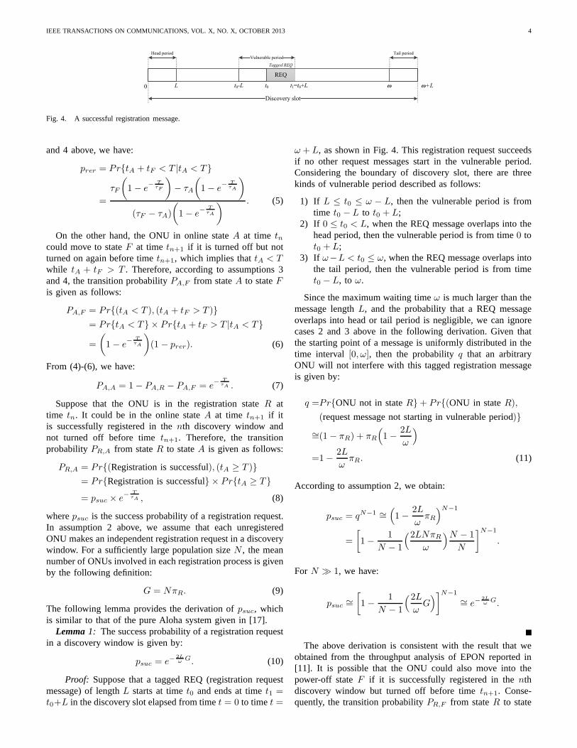
Fig. 4. A successful registration message.
and 4 above, we have:
prer = Pr{tA + tF < T |tA < T }
=
τF
(
1− e−
T
τF
)
− τA
(
1− e−
T
τA
)
(τF − τA)
(
1− e−
T
τA
) . (5)
On the other hand, the ONU in online stateA at time tncould move to stateF at time tn+1 if it is turned off but notturned on again before timetn+1, which implies thattA < Twhile tA + tF > T . Therefore, according to assumptions 3and 4, the transition probabilityPA,F from stateA to stateFis given as follows:
PA,F = Pr{(tA < T ), (tA + tF > T )}
= Pr{tA < T } × Pr{tA + tF > T |tA < T }
=
(
1− e−
T
τA
)
(1 − prer). (6)
From (4)-(6), we have:
PA,A = 1− PA,R − PA,F = e−
T
τA . (7)
Suppose that the ONU is in the registration stateR attime tn. It could be in the online stateA at time tn+1 if itis successfully registered in thenth discovery window andnot turned off before timetn+1. Therefore, the transitionprobabilityPR,A from stateR to stateA is given as follows:
PR,A = Pr{(Registration is successful), (tA ≥ T )}
= Pr{Registration is successful} × Pr{tA ≥ T }
= psuc × e−
T
τA , (8)
wherepsuc is the success probability of a registration request.In assumption 2 above, we assume that each unregisteredONU makes an independent registration request in a discoverywindow. For a sufficiently large population sizeN , the meannumber of ONUs involved in each registration process is givenby the following definition:
G = NπR. (9)
The following lemma provides the derivation ofpsuc, whichis similar to that of the pure Aloha system given in [17].
Lemma1: The success probability of a registration requestin a discovery window is given by:
psuc = e−2L
ωG. (10)
Proof: Suppose that a tagged REQ (registration requestmessage) of lengthL starts at timet0 and ends at timet1 =t0+L in the discovery slot elapsed from timet = 0 to timet =
ω + L, as shown in Fig. 4. This registration request succeedsif no other request messages start in the vulnerable period.Considering the boundary of discovery slot, there are threekinds of vulnerable period described as follows:
1) If L ≤ t0 ≤ ω − L, then the vulnerable period is fromtime t0 − L to t0 + L;
2) If 0 ≤ t0 < L, when the REQ message overlaps into thehead period, then the vulnerable period is from time0 tot0 + L;
3) If ω−L < t0 ≤ ω, when the REQ message overlaps intothe tail period, then the vulnerable period is from timet0 − L, to ω.
Since the maximum waiting timeω is much larger than themessage lengthL, and the probability that a REQ messageoverlaps into head or tail period is negligible, we can ignorecases 2 and 3 above in the following derivation. Given thatthe starting point of a message is uniformly distributed in thetime interval [0, ω], then the probabilityq that an arbitraryONU will not interfere with this tagged registration messageis given by:
q =Pr{ONU not in stateR}+ Pr{(ONU in stateR),
(request message not starting in vulnerable period)}
∼=(1− πR) + πR
(
1−2L
ω
)
=1−2L
ωπR. (11)
According to assumption 2, we obtain:
psuc = qN−1 ∼=(
1−2L
ωπR
)N−1
=
[
1−1
N − 1
(2LNπR
ω
)N − 1
N
]N−1
.
For N ≫ 1, we have:
psuc ∼=
[
1−1
N − 1
(2L
ωG)
]N−1
∼= e−2L
ωG.
The above derivation is consistent with the result that weobtained from the throughput analysis of EPON reported in[11]. It is possible that the ONU could also move into thepower-off stateF if it is successfully registered in thenthdiscovery window but turned off before timetn+1. Conse-quently, the transition probabilityPR,F from stateR to state
IEEE TRANSACTIONS ON COMMUNICATIONS, VOL. X, NO. X, OCTOBER2013 5
F can be determined as follows:
PR,F =Pr{(Registration is successful), (tA < T ), (tA+
tF > T )}
=psuc × Pr{(tA < T ), (tA + tF > T )}
=psuc × Pr{tA < T } × Pr{tA + tF > T |tA < T }
=psuc ×
(
1− e−
T
τA
)
× (1 − prer). (12)
Again, from (8) and (12), we obtain the transition probabilityPR,R that the ONU remains in stateR as follows:
PR,R = 1− PR,A − PR,F
= 1− psuc + psuc ×
(
1− e−
T
τA
)
× prer. (13)
In practice, the cycle timeT is on the order of hundredsof milliseconds [1], [18], and it is much smaller thanτA andτF , because users are not likely to turn on and off the ONUsvery frequently. Based on this practical condition, we obtainthe following approximations, which are helpful to make thecomputation of our model more tractable.
Lemma2: If τA, τF ≫ T , then we have:A1) prer ≈ 0;A2) πA
πF
∼= τAτF
.Proof: Ignoring the higher order terms in the Taylor’s
series expansione−x ≈ 1− x + o(x) for |x| ≪ 1, we obtainA1 from (5) as follows:
prer ≈
τF
[
1−(
1− TτF
)
]
− τA
[
1−(
1− TτA
)
]
(τF − τA)
(
1− e−
T
τA
) = 0.
From the first and second balance equations of (1) and thetransition probabilities given by (3), (6)-(8), and (12), we have:
πA
πF
=(1− PF,F )PR,A
PA,FPR,A + (1− PA,A)PR,F
=
(
1− e−
T
τF
)
× e−
T
τA
(
1− e−
T
τA
)
× (1− prer)
.
Similarly, we obtain A2 as follows:
πA
πF
∼=
[
1−(
1− TτF
)
]
×(
1− TτA
)
[
1−(
1− TτA
)
] =τA
(
1− TτA
)
τF∼=
τAτF
.
Given the transition probabilities (2)-(8) and (12)-(13) inthe steady-state, the set of equations (1) can be simultaneouslysolved with the characteristic equation of throughput given inthe following theorem.
Theorem1: In the steady-state of the EPON registrationprocess, the limiting probabilityπR of the Markov chainsatisfies the following characteristic equation:
(1− πR)h = πRe−
2LN
ωπR , (14)
whereh is a constant approximately given by:
h ∼=T
τA + τF. (15)
Proof: In the steady-state of the EPON registration pro-cess, from the first balance equation of (1), we obtain:
πA =πRPR,A
1− PA,A
. (16)
Clearly, we haveπA+πF +πR = 1, because each ONU mustbe in one of the three states at the beginning of any discoverywindow. Substituting (16) into the second balance equationof(1), we obtain:(
1−πR−πRPR,A
1− PA,A
)
(1−PF,F ) =πRPR,A
1− PA,A
PA,F +πRPR,F .
(17)Now, we can derive (14) from (17) together with the transitionprobabilities given by (3), (6)-(8), and (12), whereh is aconstant given as follows:
h =
(
1− e−
T
τA
)(
1− e−
T
τF
)
1− e−
(
T
τA+ T
τF
)
− prer
(
1− e−
T
τA
) .
The approximation ofh given by (15) can be readily obtainedfrom A1 of Lemma 2.
The above theorem gives the fundamental equation (14)of EPON that characterizes the throughput of the system.Multiplying both sides of (14) byN , we obtain:
N(1− πR)h = NπRe−
2LN
ωπR . (18)
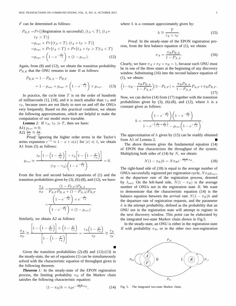
The right-hand side of (18) is equal to the average number ofONUs successfully registered per registration cycle,NπRpsuc,or the departure rateof the registration process, denotedby λout. On the left-hand side,N(1 − πR) is the averagenumber of ONUs not in the registration stateR. We wantto demonstrate that the characteristic equation (14) is thebalance equation between thearrival rate N(1 − πR)h andthe departure rate of registration requests, and the parameterh is theattempt probability, defined as the probability that anONU not in the registration state will attempt to register inthe next discovery window. This point can be elaborated bythe integrated two-state Markov chain shown in Fig.5.
In the steady-state, an ONU is either in the registration stateR with probability πR, or in the other two non-registration
R P1,1
P0,1
P1,0
P0,0
A
F
0 1
Fig. 5. The integrated two-state Markov chain.
IEEE TRANSACTIONS ON COMMUNICATIONS, VOL. X, NO. X, OCTOBER2013 6
0 40 80 120 160 200 240 280 320 360 400
0.0
0.1
0.2
0.3
0.4
0.5
0.6
0.7
0.8
0.9
1.0
stable region
saturated region
unpredictable region
ω0≈38.6µs
Analytical result: πd
R
Analytical result: πs
R
Analytical result: πu
R
Simulation result: πd
R
Simulation result: πs
R
Ste
ady
-sta
te p
rob
abil
ity
πR
Maximum waiting time ω (µs) ω−1≈317.8µs
(a)
0 40 80 120 160 200 240 280 320 360 400
0.0
0.5
1.0
1.5
2.0
2.5
3.0
Desired throughput of Analysis
Undesired throughput of Analysis
Desired throughput of Simulation
Undesired throughput of Simulation
stable region
saturated regionunpredictable region
ω0≈38.6µs
Ste
ady
-sta
te T
hro
ug
hp
ut
Maximum waiting time ω (µs) ω−1≈317.8µs
(b)
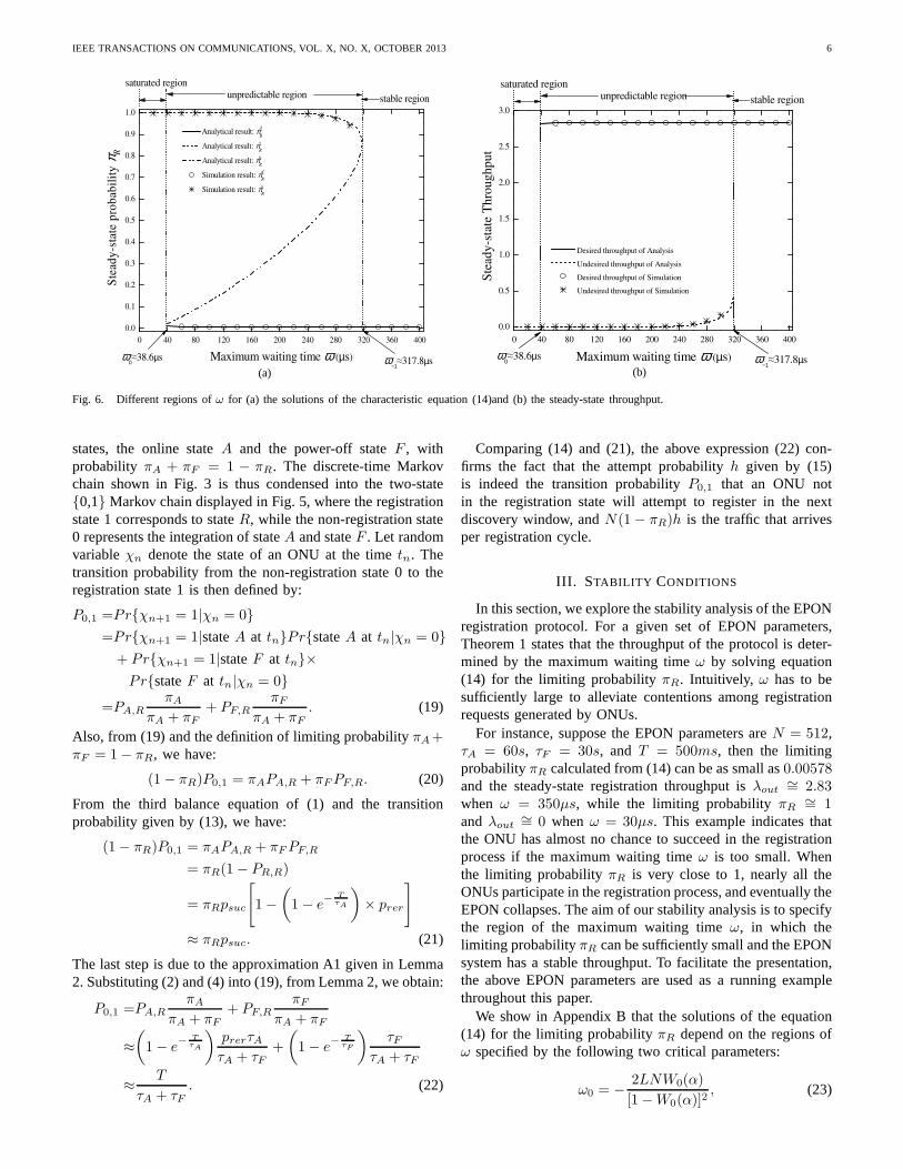
Fig. 6. Different regions ofω for (a) the solutions of the characteristic equation (14)and (b) the steady-state throughput.
states, the online stateA and the power-off stateF , withprobability πA + πF = 1 − πR. The discrete-time Markovchain shown in Fig. 3 is thus condensed into the two-state{0,1} Markov chain displayed in Fig. 5, where the registrationstate 1 corresponds to stateR, while the non-registration state0 represents the integration of stateA and stateF . Let randomvariableχn denote the state of an ONU at the timetn. Thetransition probability from the non-registration state 0 to theregistration state 1 is then defined by:
P0,1 =Pr{χn+1 = 1|χn = 0}
=Pr{χn+1 = 1|stateA at tn}Pr{stateA at tn|χn = 0}
+ Pr{χn+1 = 1|stateF at tn}×
Pr{stateF at tn|χn = 0}
=PA,R
πA
πA + πF
+ PF,R
πF
πA + πF
. (19)
Also, from (19) and the definition of limiting probabilityπA+πF = 1− πR, we have:
(1− πR)P0,1 = πAPA,R + πFPF,R. (20)
From the third balance equation of (1) and the transitionprobability given by (13), we have:
(1− πR)P0,1 = πAPA,R + πFPF,R
= πR(1− PR,R)
= πRpsuc
[
1−
(
1− e−
T
τA
)
× prer
]
≈ πRpsuc. (21)
The last step is due to the approximation A1 given in Lemma2. Substituting (2) and (4) into (19), from Lemma 2, we obtain:
P0,1 =PA,R
πA
πA + πF
+ PF,R
πF
πA + πF
≈
(
1− e−
T
τA
)
prerτAτA + τF
+
(
1− e−
T
τF
)
τFτA + τF
≈T
τA + τF. (22)
Comparing (14) and (21), the above expression (22) con-firms the fact that the attempt probabilityh given by (15)is indeed the transition probabilityP0,1 that an ONU notin the registration state will attempt to register in the nextdiscovery window, andN(1− πR)h is the traffic that arrivesper registration cycle.
III. STABILITY CONDITIONS
In this section, we explore the stability analysis of the EPONregistration protocol. For a given set of EPON parameters,Theorem 1 states that the throughput of the protocol is deter-mined by the maximum waiting timeω by solving equation(14) for the limiting probabilityπR. Intuitively, ω has to besufficiently large to alleviate contentions among registrationrequests generated by ONUs.
For instance, suppose the EPON parameters areN = 512,τA = 60s, τF = 30s, and T = 500ms, then the limitingprobabilityπR calculated from (14) can be as small as0.00578and the steady-state registration throughput isλout
∼= 2.83when ω = 350µs, while the limiting probabilityπR
∼= 1and λout
∼= 0 when ω = 30µs. This example indicates thatthe ONU has almost no chance to succeed in the registrationprocess if the maximum waiting timeω is too small. Whenthe limiting probabilityπR is very close to 1, nearly all theONUs participate in the registration process, and eventually theEPON collapses. The aim of our stability analysis is to specifythe region of the maximum waiting timeω, in which thelimiting probabilityπR can be sufficiently small and the EPONsystem has a stable throughput. To facilitate the presentation,the above EPON parameters are used as a running examplethroughout this paper.
We show in Appendix B that the solutions of the equation(14) for the limiting probabilityπR depend on the regions ofω specified by the following two critical parameters:
ω0 = −2LNW0(α)
[1−W0(α)]2, (23)
IEEE TRANSACTIONS ON COMMUNICATIONS, VOL. X, NO. X, OCTOBER2013 7
0 500 1000 1500 2000 2500 30000.0
0.1
0.2
0.3
0.4
0.5
0.6
0.7
0.8
0.9
1.0
0% initial ONUs in State R
60% initial ONUs in State R
Fra
ctio
n o
f O
NU
s in
Sta
te R
Number of the registration cycles
(a) Saturated region:ω < ω0
0 500 1000 1500 2000 2500 30000.0
0.1
0.2
0.3
0.4
0.5
0.6
0.7
0.8
0.9
1.0
69.96% initial ONUs in State R
69.96% initial ONUs in State R
Fra
ctio
n o
f O
NU
s in
Sta
te R
Number of the registration cycles
(b) Unpredictable region:ω0 < ω < ω−1
0 500 1000 1500 2000 2500 30000.0
0.1
0.2
0.3
0.4
0.5
0.6
0.7
0.8
0.9
1.0
0% initial ONUs in State R
98% initial ONUs in State R
Fra
ctio
n o
f O
NU
s in
Sta
te R
Number of the registration cycles
(c) Stable region:ω > ω−1
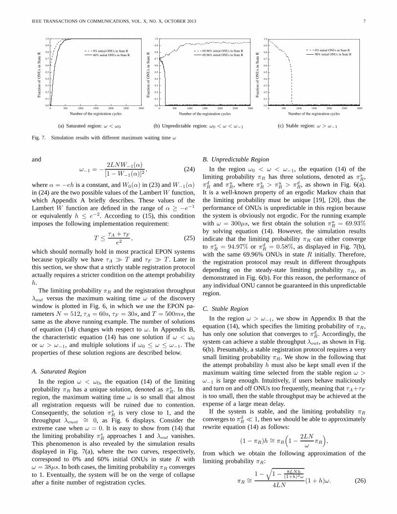
Fig. 7. Simulation results with different maximum waiting time ω
and
ω−1 = −2LNW−1(α)
[1−W−1(α)]2, (24)
whereα = −eh is a constant, andW0(α) in (23) andW−1(α)in (24) are the two possible values of the LambertW function,which Appendix A briefly describes. These values of theLambertW function are defined in the range ofα ≥ −e−1
or equivalentlyh ≤ e−2. According to (15), this conditionimposes the following implementation requirement:
T ≤τA + τF
e2, (25)
which should normally hold in most practical EPON systemsbecause typically we haveτA ≫ T and τF ≫ T . Later inthis section, we show that a strictly stable registration protocolactually requires a stricter condition on the attempt probabilityh.
The limiting probabilityπR and the registration throughputλout versus the maximum waiting timeω of the discoverywindow is plotted in Fig. 6, in which we use the EPON pa-rametersN = 512, τA = 60s, τF = 30s, andT = 500ms, thesame as the above running example. The number of solutionsof equation (14) changes with respect toω. In Appendix B,the characteristic equation (14) has one solution ifω < ω0
or ω > ω−1, and multiple solutions ifω0 ≤ ω ≤ ω−1. Theproperties of these solution regions are described below.
A. Saturated Region
In the regionω < ω0, the equation (14) of the limitingprobability πR has a unique solution, denoted asπs
R. In thisregion, the maximum waiting timeω is so small that almostall registration requests will be ruined due to contention.Consequently, the solutionπs
R is very close to 1, and thethroughputλouot
∼= 0, as Fig. 6 displays. Consider theextreme case whenω = 0. It is easy to show from (14) thatthe limiting probabilityπs
R approaches 1 andλout vanishes.This phenomenon is also revealed by the simulation resultsdisplayed in Fig. 7(a), where the two curves, respectively,correspond to 0% and 60% initial ONUs in stateR withω = 38µs. In both cases, the limiting probabilityπR convergesto 1. Eventually, the system will be on the verge of collapseafter a finite number of registration cycles.
B. Unpredictable Region
In the regionω0 < ω < ω−1, the equation (14) of thelimiting probability πR has three solutions, denoted asπs
R,πdR and πu
R, whereπsR > πu
R > πdR, as shown in Fig. 6(a).
It is a well-known property of an ergodic Markov chain thatthe limiting probability must be unique [19], [20], thus theperformance of ONUs is unpredictable in this region becausethe system is obviously not ergodic. For the running examplewith ω = 300µs, we first obtain the solutionπu
R = 69.93%by solving equation (14). However, the simulation resultsindicate that the limiting probabilityπR can either convergeto πs
R = 94.97% or πdR = 0.58%, as displayed in Fig. 7(b),
with the same 69.96% ONUs in stateR initially. Therefore,the registration protocol may result in different throughputsdepending on the steady-state limiting probabilityπR, asdemonstrated in Fig. 6(b). For this reason, the performanceofany individual ONU cannot be guaranteed in this unpredictableregion.
C. Stable Region
In the regionω > ω−1, we show in Appendix B that theequation (14), which specifies the limiting probability ofπR,has only one solution that converges toπd
R. Accordingly, thesystem can achieve a stable throughputλout, as shown in Fig.6(b). Presumably, a stable registration protocol requiresa verysmall limiting probabilityπR. We show in the following thatthe attempt probabilityh must also be kept small even if themaximum waiting time selected from the stable regionω >ω−1 is large enough. Intuitively, if users behave maliciouslyand turn on and off ONUs too frequently, meaning thatτA+τFis too small, then the stable throughput may be achieved at theexpense of a large mean delay.
If the system is stable, and the limiting probabilityπR
converges toπdR ≪ 1, then we should be able to approximately
rewrite equation (14) as follows:
(1− πR)h ∼= πR
(
1−2LN
ωπR
)
,
from which we obtain the following approximation of thelimiting probability πR:
πR∼=
1−√
1− 8LNh(1+h)2ω
4LN(1 + h)ω. (26)
IEEE TRANSACTIONS ON COMMUNICATIONS, VOL. X, NO. X, OCTOBER2013 8
10-3
10-2
10-1
100
0
100
200
300
400
500
600
700
2h e
−′ =
1ω∗−
ω −1 (
µs)
h
1
16h
∗ =
Fig. 8. Parameterω−1 versus attempt probabilityh.
The maximum waiting timeω should satisfy the followingcondition if the above expression (26) is valid:
ω ≥8LNh
(1 + h)2.
Thus, the stable condition of an EPON registration protocolisformally defined as follows:
Definition 1: The EPON registration protocol is stable ifthe maximum waiting timeω is selected from the rangeω >ω−1. Moreover, the protocol is strictly stable if the attemptprobability h satisfies the following inequality:
ω > ω−1 >8LNh
(1 + h)2. (27)
In the following corollary, the above inequality (27) induces anecessary condition for a strictly stable registration protocol.
Corollary 1: A strictly stable registration protocol satisfiesthe following necessary condition:
h <1
16. (28)
Proof: According to (24), the stable condition requiresthat:
ω ≥ ω−1 = −2LNW−1(α)
[1−W−1(α)]2. (29)
Thus, the following condition on the attempt probabilityh > 0ensures that both inequalities (27) and (29) can always besatisfied:
−2LNW−1(α)
[1−W−1(α)]2> 8LNh >
8LNh
(1 + h)2,
which is equivalent to:
h < −W−1(α)
4[1−W−1(α)]2. (30)
We know from Fig. 12 in Appendix A thatW−1(α) = −c2
for somec ≥ 1, therefore the above inequality implies that:
h <c2
4(1 + c2)2=
1
4(
1c+ c
)2 ≤1
16.
10-3
10-2
10-1
100
0.0
0.1
0.2
0.3
0.4
0.5
2h e
−′ =
Lower Bound:
1
16h
∗ =
1
h
h+
eh
π R
h
( )( )
0
01
W
W
αα
−−
πR when ω = ω
-1
Upper Bound:
Fig. 9. The limiting probabilityπR versus attempt probabilityh
Using the same EPON parameters of our running example,we show in Fig. 8 that parameterω−1 increases with respectto h. In particular, parameterω−1 skyrockets whenh > 1/16,which clearly demonstrates the necessity of the condition givenby (28) for a strictly stable registration protocol.
We know from (14) that the arrival rate of registrationrequests per cycle timeT is N(1 − πR)h. For a givenregistration cycleT , a smaller attempt probabilityh implieslarger τA and τF , meaning that the users tend to switch theONUs on and off less frequently. Therefore, the ONUs areless likely to engage in a registration process. As a result,thearrival traffic for registration requests becomes smaller,whichin turn decreases the probability of collision. Therefore,fora smaller attempt probabilityh, a smaller maximum waitingtime ω is required to moderate the collisions. This point isreinforced in the following corollary.
Corollary 2: Suppose the maximum waiting time is se-lected from the regionω > ω−1. Then the unique limitingprobabilityπR is bounded by:
h
1 + h≤ πR ≤ −
W0(α)
1−W0(α)∼= eh, (31)
where the approximation of the upper bound is valid for smallattempt probabilityh.
Proof: In Appendix B, we prove that ifω > ω−1 thenthe equation (14), which specifies the limiting probabilityofπR, has a unique solution in the interval
[
0,− W0(α)1−W0(α)
]
. InAppendix A, we show thatW0(α) has the following seriesexpansion:
W0(α) =
∞∑
i=1
(−i)i−1
i!αi = α− α2 +
3
2α3 −
8
3α4 + · · · ,
which is approximately equal toα = −eh when the attemptprobability h is small. That is, if the maximum waiting timeω is large enough and the attempt probabilityh is small, i.e.,−α ≪ 1, then we have:
πR ≪ −W0(α)
1−W0(α)≈ −W0(α) ≈ −α = eh.
When the maximum waiting timeω approaches infinity, weobtain the lower bound of the limiting probabilityπR from
IEEE TRANSACTIONS ON COMMUNICATIONS, VOL. X, NO. X, OCTOBER2013 9
T D T D T…… ……
T
time
ton
dadr
tsucd
……
Z
D
tnext
tlast
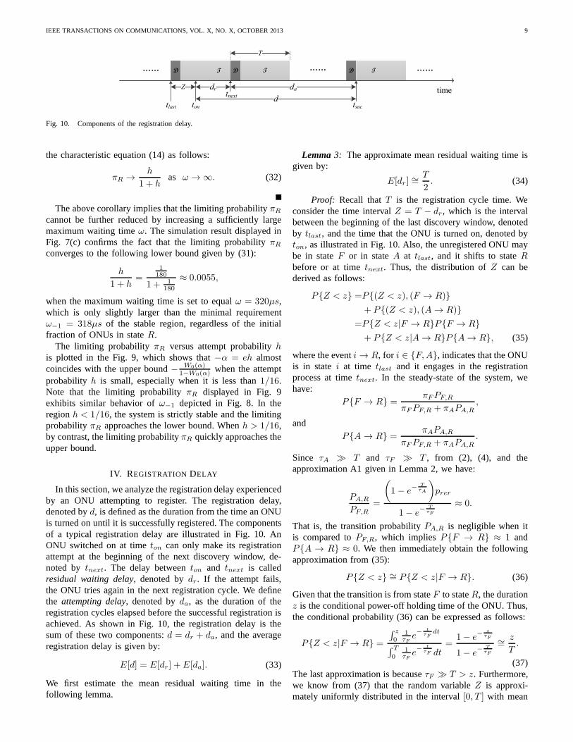
Fig. 10. Components of the registration delay.
the characteristic equation (14) as follows:
πR →h
1 + has ω → ∞. (32)
The above corollary implies that the limiting probabilityπR
cannot be further reduced by increasing a sufficiently largemaximum waiting timeω. The simulation result displayed inFig. 7(c) confirms the fact that the limiting probabilityπR
converges to the following lower bound given by (31):
h
1 + h=
1180
1 + 1180
≈ 0.0055,
when the maximum waiting time is set to equalω = 320µs,which is only slightly larger than the minimal requirementω−1 = 318µs of the stable region, regardless of the initialfraction of ONUs in stateR.
The limiting probabilityπR versus attempt probabilityhis plotted in the Fig. 9, which shows that−α = eh almostcoincides with the upper bound− W0(α)
1−W0(α)when the attempt
probability h is small, especially when it is less than1/16.Note that the limiting probabilityπR displayed in Fig. 9exhibits similar behavior ofω−1 depicted in Fig. 8. In theregionh < 1/16, the system is strictly stable and the limitingprobabilityπR approaches the lower bound. Whenh > 1/16,by contrast, the limiting probabilityπR quickly approaches theupper bound.
IV. REGISTRATION DELAY
In this section, we analyze the registration delay experiencedby an ONU attempting to register. The registration delay,denoted byd, is defined as the duration from the time an ONUis turned on until it is successfully registered. The componentsof a typical registration delay are illustrated in Fig. 10. AnONU switched on at timeton can only make its registrationattempt at the beginning of the next discovery window, de-noted by tnext. The delay betweenton and tnext is calledresidual waiting delay, denoted bydr. If the attempt fails,the ONU tries again in the next registration cycle. We definethe attempting delay, denoted byda, as the duration of theregistration cycles elapsed before the successful registration isachieved. As shown in Fig. 10, the registration delay is thesum of these two components:d = dr + da, and the averageregistration delay is given by:
E[d] = E[dr] + E[da]. (33)
We first estimate the mean residual waiting time in thefollowing lemma.
Lemma3: The approximate mean residual waiting time isgiven by:
E[dr] ∼=T
2. (34)
Proof: Recall thatT is the registration cycle time. Weconsider the time intervalZ = T − dr, which is the intervalbetween the beginning of the last discovery window, denotedby tlast, and the time that the ONU is turned on, denoted byton, as illustrated in Fig. 10. Also, the unregistered ONU maybe in stateF or in stateA at tlast, and it shifts to stateRbefore or at timetnext. Thus, the distribution ofZ can bederived as follows:
P{Z < z} =P{(Z < z), (F → R)}
+ P{(Z < z), (A → R)}
=P{Z < z|F → R}P{F → R}
+ P{Z < z|A → R}P{A→ R}, (35)
where the eventi → R, for i ∈ {F,A}, indicates that the ONUis in statei at time tlast and it engages in the registrationprocess at timetnext. In the steady-state of the system, wehave:
P{F → R} =πFPF,R
πFPF,R + πAPA,R
,
andP{A → R} =
πAPA,R
πFPF,R + πAPA,R
.
Since τA ≫ T and τF ≫ T , from (2), (4), and theapproximation A1 given in Lemma 2, we have:
PA,R
PF,R
=
(
1− e−
T
τA
)
prer
1− e−
T
τF
≈ 0.
That is, the transition probabilityPA,R is negligible when itis compared toPF,R, which impliesP{F → R} ≈ 1 andP{A → R} ≈ 0. We then immediately obtain the followingapproximation from (35):
P{Z < z} ∼= P{Z < z|F → R}. (36)
Given that the transition is from stateF to stateR, the durationz is the conditional power-off holding time of the ONU. Thus,the conditional probability (36) can be expressed as follows:
P{Z < z|F → R} =
∫ z
01τF
e−
t
τFdt
∫ T
01τF
e−
t
τF dt=
1− e−
z
τF
1− e−
T
τF
∼=z
T.
(37)The last approximation is becauseτF ≫ T > z. Furthermore,we know from (37) that the random variableZ is approxi-mately uniformly distributed in the interval[0, T ] with mean
IEEE TRANSACTIONS ON COMMUNICATIONS, VOL. X, NO. X, OCTOBER2013 10
E[Z] ∼= T/2. As a result, the average residual waiting time isgiven by:
E[dr] = E[T − Z] ∼=T
2.
Let k(k = 1, 2, 3, · · · ) be the number of discovery windowselapsed until an attempting ONU could register successfully.Whenk = 1, the attempting delay of the ONU is the durationof a single discovery window. Whenk = 2, the attemptingdelay of the ONU consists of a registration cycle and a singlediscovery window. In general, as illustrated in Fig. 10, theONU spendsk − 1 registration cycles and a single discoverywindow on the registration. Hence, the attempting delay isgiven by:
da = M + (k − 1)T, (38)
whereM is the discovery window size defined in Section II-A.Summarizing the above discussions, the mean registrationdelay is provided in the following theorem.
Theorem2: Suppose the maximum waiting time is selectedin the stable regionω > ω−1 or the saturated regionω < ω0.The average registration delay that an ONU experiences in theregistration processes is given by:
E[d] ∼=[ πR
(1− πR)h−
1
2
]
T. (39)
If the registration protocol is stable, the average delay isupperbounded by
E[d] ≤ 6.89T. (40)
Proof: We know from (38) that the average attemptingdelay is given by:
E[da] = M + (E[k]− 1)T ∼= (E[k]− 1)T, (41)
where the discovery window sizeM can be ignored becauseit is typically much smaller thanT . Recall that, in the steady-state of EPON, an ONU attempting to register succeedsin a discovery window with probabilitypsuc. Thus, k is ageometric random variable with parameterpsuc. From (14),we have:
E[k] =1
psuc=
πR
(1− πR)h. (42)
It follows from (41) and (42) that:
E[da] ∼=[ πR
(1− πR)h− 1
]
T. (43)
Substituting (34) and (43) into (33), we immediately obtain(39).
If the system is stable, we know from Corollary 2 thatthe limiting probabilityπR is upper bounded by− W0(α)
1−W0(α).
Moreover, we know from (39) that the mean delay is upperbounded by:
E[d] ∼=[ πR
(1 − πR)h−
1
2
]
T ≤
{
− W0(α)1−W0(α)
[
1 + W0(α)1−W0(α)
]
h−
1
2
}
T
=[
−W0(α)
h−
1
2
]
T =[eW0(α)
−eh−
1
2
]
T
=[eW0(α)
α−
1
2
]
T. (44)
300 400 500 600 700 8000
50
100
150
200
250
300
Mean delay E[d] of Simulation
Mean delay E[d] of Analysis
Efficiency η of Simulation
Efficiency η of Analysis
Maximum waiting time ω (µs)
Mea
n d
elay
E[d
] (m
s)
0.002
0.003
0.004
0.005
0.006
Reg
istr
atio
n e
ffic
ien
cy η
(R
eqs/
µs)
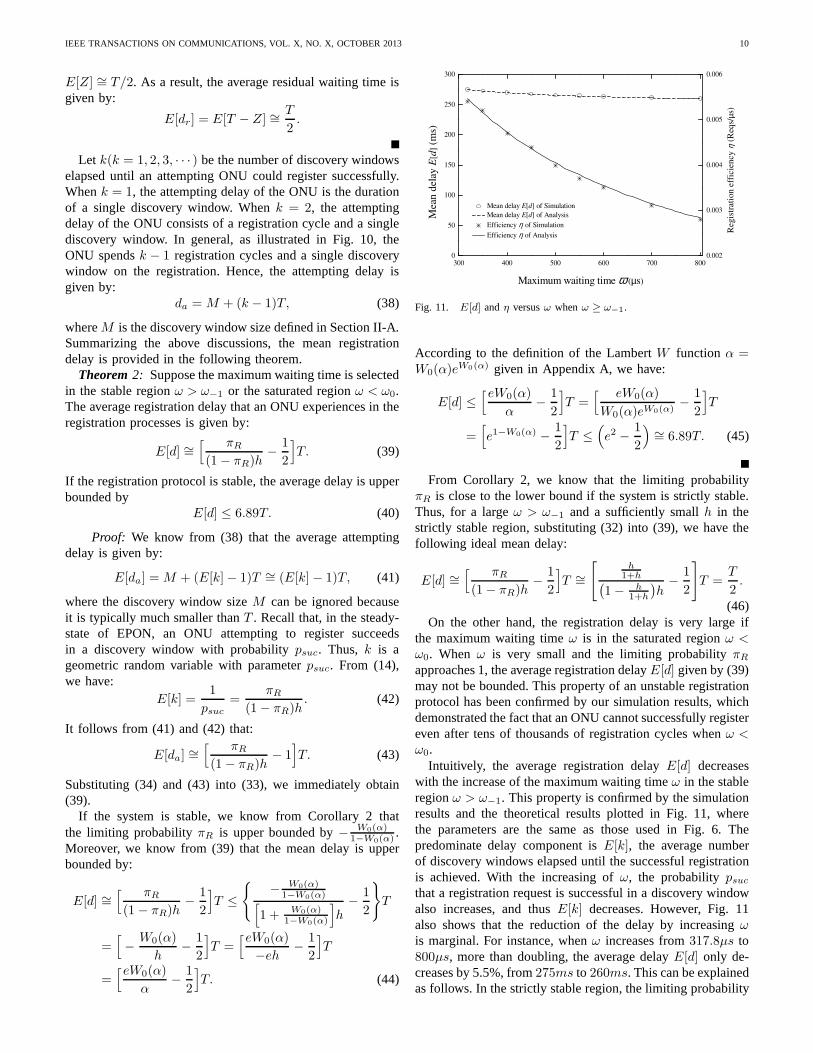
Fig. 11. E[d] andη versusω whenω ≥ ω−1.
According to the definition of the LambertW function α =W0(α)e
W0(α) given in Appendix A, we have:
E[d] ≤[eW0(α)
α−
1
2
]
T =[ eW0(α)
W0(α)eW0(α)−
1
2
]
T
=[
e1−W0(α) −1
2
]
T ≤(
e2 −1
2
)
∼= 6.89T. (45)
From Corollary 2, we know that the limiting probabilityπR is close to the lower bound if the system is strictly stable.Thus, for a largeω > ω−1 and a sufficiently smallh in thestrictly stable region, substituting (32) into (39), we have thefollowing ideal mean delay:
E[d] ∼=[ πR
(1− πR)h−
1
2
]
T ∼=
[
h1+h
(
1− h1+h
)
h−
1
2
]
T =T
2.
(46)On the other hand, the registration delay is very large if
the maximum waiting timeω is in the saturated regionω <ω0. When ω is very small and the limiting probabilityπR
approaches 1, the average registration delayE[d] given by (39)may not be bounded. This property of an unstable registrationprotocol has been confirmed by our simulation results, whichdemonstrated the fact that an ONU cannot successfully registereven after tens of thousands of registration cycles whenω <ω0.
Intuitively, the average registration delayE[d] decreaseswith the increase of the maximum waiting timeω in the stableregionω > ω−1. This property is confirmed by the simulationresults and the theoretical results plotted in Fig. 11, wherethe parameters are the same as those used in Fig. 6. Thepredominate delay component isE[k], the average numberof discovery windows elapsed until the successful registrationis achieved. With the increasing ofω, the probabilitypsucthat a registration request is successful in a discovery windowalso increases, and thusE[k] decreases. However, Fig. 11also shows that the reduction of the delay by increasingωis marginal. For instance, whenω increases from317.8µs to800µs, more than doubling, the average delayE[d] only de-creases by 5.5%, from275ms to 260ms. This can be explainedas follows. In the strictly stable region, the limiting probability
IEEE TRANSACTIONS ON COMMUNICATIONS, VOL. X, NO. X, OCTOBER2013 11
πR is already very small and, thus, can only be reduced slightlyby increasingω, as demonstrated by (32). It follows from (42)that the improvement inpsuc, or equivalently the reduction ofE[k], is insignificant. Consequently, the reduction ofE[d] byincreasingω is negligible, as predicted by (46).
In contrast, the increase ofω not only shrinks the bandwidthavailable for normal transmission, but also affects the regis-tration efficiency. In [1], [11], this indicator, denoted byη, isdefined as the ratio of the number of successful registrationsto the discovery window size and is given as follows:
η =NπRpsuc
M=
Nh(1− πR)
2Q+D∼=
Nh
2Q+ ω + L, (47)
where the second equality is obtained from (14) and the lastapproximation is due to the conditionπR ≪ 1. A comparisonof E[d] in (46) and η in (47) shows that the efficiencyηdrops much faster than then mean delayE[d] in respect to theincrease ofω. This point is also confirmed by the simulationresults displayed in Fig. 11, which shows that the efficiencyηis reduced by almost half whenω increases from317.8µs to800µs. Thus, a marginal reduction of the delay is achievedat the expense of a substantial degradation of registrationefficiencyη.
V. CONCLUSION
In this paper, we analyze the stability and delay of theEPON registration protocol. We first establish a model of thesubscribers by using a discrete-time Markov chain, and thenderive the characteristic function to delineate the throughputof the registration process. Solving the characteristic function,we obtain the region of the maximum waiting time to makethe registration protocol stable. If the maximum waiting timeis selected from this region, we show that a stable regis-tration throughput and a bounded registration delay can beguaranteed. Our results also indicate that it is unnecessary toarbitrarily enlarge the maximum waiting time as long as itis in the stable region since the improvement of registrationdelay is marginal, yet the reduction of registration efficiencyis quite significant.
APPENDIX ALAMBERT W FUNCTION.
The LambertW functionW (z), which was first consideredby J. Lambert [21], is defined as the function satisfying:
W (z)eW (z) = z. (48)
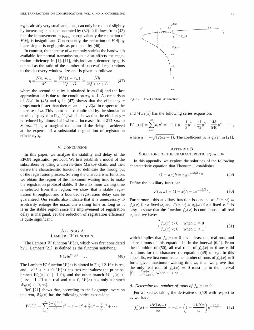
The LambertW functionW (z) is plotted in Fig. 12. Ifz is realand−e−1 < z < 0, W (z) has two real values: the principalbranchW0(z) ∈ [−1, 0), and the other branchW−1(z) ∈(−∞,−1]. If z is real andz > 0, W (z) has only a branchW0(z) ∈ [0,∞).
Ref. [21] shows that, according to the Lagrange inversiontheorem,W0(z) has the following series expansion:
W0(z) =
∞∑
i=1
(−i)i−1
i!zi = z − z2 +
3
2z3 −
8
3z4 + · · · ,
0.0 0.5
-10
-8
-6
-4
-2
-1
0
W-1(x)
z
W(z)
-e-1
W0(x)
Fig. 12. The LambertW function.
andW−1(z) has the following series expansion:
W−1(z) =
∞∑
i=0
µiyi = −1+ y−
1
3y2 +
11
72y3 −
43
540y4 + · · · ,
wherey = −√
(2(ez + 1). The coefficientµi is given in [21].
APPENDIX BSOLUTIONS OF THE CHARACTERISTIC EQUATION
In this appendix, we explore the solutions of the followingcharacteristic equation that Theorem 1 establishes:
(1− πR)h = πRe−
2LN
ωπR , (49)
Define the auxiliary function:
F (x, ω) = (1 − x)h− xe−2LN
ωx, (50)
Furthermore, this auxiliary function is denoted asF (x, ω) =fω(x) for a fixedω, andF (x, ω) = gx(ω) for a fixedx. It iseasy to show that the functionfω(x) is continuous at all realx, and we have:
{
fω(x) > 0, whenx ≤ 0
fω(x) < 0, whenx ≥ 1, (51)
which implies thatfω(x) = 0 has at least one real root, andall real roots of this equation lie in the interval[0, 1]. Fromthe definition of (50), all real roots offω(x) = 0 are validsolutions for the characteristic equation (49) ofπR. In thisappendix, we first enumerate the number of roots offω(x) = 0for a given maximum waiting timeω, then we prove thatthe only real root offω(x) = 0 must lie in the interval[
0,− W0(α)1−W0(α)
]
whenω > ω−1.
A. Determine the number of roots offω(x) = 0
For a fixedω, taking the derivative of (50) with respect tox, we have:
f ′
ω(x) =∂F (x, ω)
∂x= −h−
(
1−2LNx
ω
)
e−2LN
ωx. (52)
IEEE TRANSACTIONS ON COMMUNICATIONS, VOL. X, NO. X, OCTOBER2013 12
TABLE ITHE NUMBER OF ROOTS OF THE EQUATIONfω(x) = 0
whereα = −eh is a constant, andW0(α) andW−1(α) arethe two possible values of the LambertW functions [14] asdescribed in Appendix A. Substituting (53) and (54) into (50),we obtain the following two possible extreme values offω(x):
fω(x0) = h+ωh[1−W0(α)]
2
2LNW0(α)= h(1−
ω
ω0), (55)
and
fω(x1) = h+ωh[1−W−1(α)]
2
2LNW−1(α)= h(1−
ω
ω−1), (56)
whereω0 andω−1 are parameters defined by (23) and (24),respectively.
0.0 0.2 0.4 0.6 0.8 1.0-0.06
-0.04
-0.02
0.00
0.02
0.04
( )( )
0
01
Wa
W
αα
= −−
1x
ω<ω0
ω=ω0
ω0<ω<ω
-1
ω=ω-1
fω
(x)
X
x
X
ω>ω-1
0x
Fig. 14. The functionfω(x) for different values ofω.
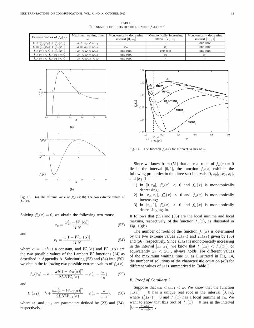
Since we know from (51) that all real roots offω(x) = 0lie in the interval [0, 1], the function fω(x) exhibits thefollowing properties in the three sub-intervals[0, x0], [x0, x1],and [x1, 1]:
1) In [0, x0], f ′
ω(x) < 0 and fω(x) is monotonicallydecreasing;
2) In [x0, x1], f ′
ω(x) > 0 and fω(x) is monotonicallyincreasing;
3) In [x1, 1], f ′
ω(x) < 0 and fω(x) is monotonicallydecreasing again.
It follows that (55) and (56) are the local minima and localmaxima, respectively, of the functionfω(x), as illustrated inFig. 13(b).
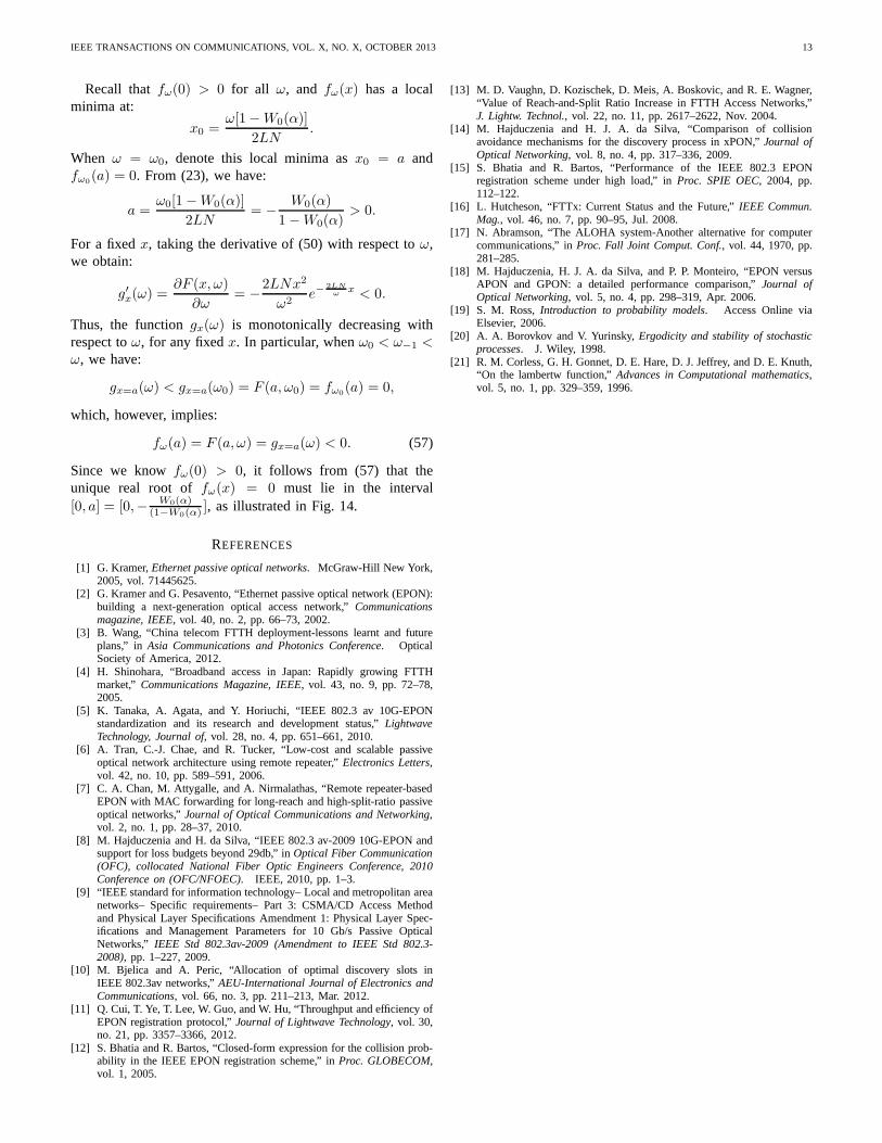
The number of roots of the functionfω(x) is determinedby the two extreme valuesfω(x0) andfω(x1) given by (55)and (56), respectively. Sincefω(x) is monotonically increasingin the interval [x0, x1], we know thatfω(x0) < fω(x1), orequivalentlyω0 < ω−1, always holds. For different valuesof the maximum waiting timeω, as illustrated in Fig. 14,the number of solutions of the characteristic equation (49)fordifferent values ofω is summarized in Table I.
B. Proof of Corollary 2
Suppose thatω0 < ω−1 < ω. We know that the functionfω(x) = 0 has a unique real root in the interval[0, x0],wheref ′
ω(x0) = 0 and fω(x) has a local minima atx0. Wewant to show that this root offω(x) = 0 lies in the interval[
0,− W0(α)1−W0(α)
]
.
IEEE TRANSACTIONS ON COMMUNICATIONS, VOL. X, NO. X, OCTOBER2013 13
Recall thatfω(0) > 0 for all ω, and fω(x) has a localminima at:
x0 =ω[1−W0(α)]
2LN.
When ω = ω0, denote this local minima asx0 = a andfω0
(a) = 0. From (23), we have:
a =ω0[1−W0(α)]
2LN= −
W0(α)
1−W0(α)> 0.
For a fixedx, taking the derivative of (50) with respect toω,we obtain:
g′x(ω) =∂F (x, ω)
∂ω= −
2LNx2
ω2e−
2LN
ωx < 0.
Thus, the functiongx(ω) is monotonically decreasing withrespect toω, for any fixedx. In particular, whenω0 < ω−1 <ω, we have:
gx=a(ω) < gx=a(ω0) = F (a, ω0) = fω0(a) = 0,
which, however, implies:
fω(a) = F (a, ω) = gx=a(ω) < 0. (57)
Since we knowfω(0) > 0, it follows from (57) that theunique real root offω(x) = 0 must lie in the interval[0, a] = [0,− W0(α)
(1−W0(α)], as illustrated in Fig. 14.
REFERENCES
[1] G. Kramer,Ethernet passive optical networks. McGraw-Hill New York,2005, vol. 71445625.
[2] G. Kramer and G. Pesavento, “Ethernet passive optical network (EPON):building a next-generation optical access network,”Communicationsmagazine, IEEE, vol. 40, no. 2, pp. 66–73, 2002.
[3] B. Wang, “China telecom FTTH deployment-lessons learntand futureplans,” in Asia Communications and Photonics Conference. OpticalSociety of America, 2012.
[4] H. Shinohara, “Broadband access in Japan: Rapidly growing FTTHmarket,” Communications Magazine, IEEE, vol. 43, no. 9, pp. 72–78,2005.
[5] K. Tanaka, A. Agata, and Y. Horiuchi, “IEEE 802.3 av 10G-EPONstandardization and its research and development status,”LightwaveTechnology, Journal of, vol. 28, no. 4, pp. 651–661, 2010.
[6] A. Tran, C.-J. Chae, and R. Tucker, “Low-cost and scalable passiveoptical network architecture using remote repeater,”Electronics Letters,vol. 42, no. 10, pp. 589–591, 2006.
[7] C. A. Chan, M. Attygalle, and A. Nirmalathas, “Remote repeater-basedEPON with MAC forwarding for long-reach and high-split-ratio passiveoptical networks,”Journal of Optical Communications and Networking,vol. 2, no. 1, pp. 28–37, 2010.
[8] M. Hajduczenia and H. da Silva, “IEEE 802.3 av-2009 10G-EPON andsupport for loss budgets beyond 29db,” inOptical Fiber Communication(OFC), collocated National Fiber Optic Engineers Conference, 2010Conference on (OFC/NFOEC). IEEE, 2010, pp. 1–3.
[9] “IEEE standard for information technology– Local and metropolitan areanetworks– Specific requirements– Part 3: CSMA/CD Access Methodand Physical Layer Specifications Amendment 1: Physical Layer Spec-ifications and Management Parameters for 10 Gb/s Passive OpticalNetworks,” IEEE Std 802.3av-2009 (Amendment to IEEE Std 802.3-2008), pp. 1–227, 2009.
[10] M. Bjelica and A. Peric, “Allocation of optimal discovery slots inIEEE 802.3av networks,”AEU-International Journal of Electronics andCommunications, vol. 66, no. 3, pp. 211–213, Mar. 2012.
[11] Q. Cui, T. Ye, T. Lee, W. Guo, and W. Hu, “Throughput and efficiency ofEPON registration protocol,”Journal of Lightwave Technology, vol. 30,no. 21, pp. 3357–3366, 2012.
[12] S. Bhatia and R. Bartos, “Closed-form expression for the collision prob-ability in the IEEE EPON registration scheme,” inProc. GLOBECOM,vol. 1, 2005.
[13] M. D. Vaughn, D. Kozischek, D. Meis, A. Boskovic, and R. E. Wagner,“Value of Reach-and-Split Ratio Increase in FTTH Access Networks,”J. Lightw. Technol., vol. 22, no. 11, pp. 2617–2622, Nov. 2004.
[14] M. Hajduczenia and H. J. A. da Silva, “Comparison of collisionavoidance mechanisms for the discovery process in xPON,”Journal ofOptical Networking, vol. 8, no. 4, pp. 317–336, 2009.
[15] S. Bhatia and R. Bartos, “Performance of the IEEE 802.3 EPONregistration scheme under high load,” inProc. SPIE OEC, 2004, pp.112–122.
[16] L. Hutcheson, “FTTx: Current Status and the Future,”IEEE Commun.Mag., vol. 46, no. 7, pp. 90–95, Jul. 2008.
[17] N. Abramson, “The ALOHA system-Another alternative for computercommunications,” inProc. Fall Joint Comput. Conf., vol. 44, 1970, pp.281–285.
[18] M. Hajduczenia, H. J. A. da Silva, and P. P. Monteiro, “EPON versusAPON and GPON: a detailed performance comparison,”Journal ofOptical Networking, vol. 5, no. 4, pp. 298–319, Apr. 2006.
[19] S. M. Ross,Introduction to probability models. Access Online viaElsevier, 2006.
[20] A. A. Borovkov and V. Yurinsky,Ergodicity and stability of stochasticprocesses. J. Wiley, 1998.
[21] R. M. Corless, G. H. Gonnet, D. E. Hare, D. J. Jeffrey, andD. E. Knuth,“On the lambertw function,”Advances in Computational mathematics,vol. 5, no. 1, pp. 329–359, 1996.