arXiv:2004.03108v2 [eess.SP] 30 Sep 2020 IEEE TRANSACTIONS ON COMMUNICATIONS, VOL. XX, NO. XX, APRIL 2020 1 Optimized Energy and Information Relaying in Self-Sustainable IRS-Empowered WPCN Bin Lyu, Member, IEEE, Parisa Ramezani, Student Member, IEEE, Dinh Thai Hoang, Member, IEEE, Shimin Gong, Member, IEEE, Zhen Yang, Senior Member, IEEE, and Abbas Jamalipour, Fellow, IEEE Abstract—This paper proposes a hybrid-relaying scheme em- powered by a self-sustainable intelligent reflecting surface (IRS) in a wireless powered communication network (WPCN), to simultaneously improve the performance of downlink energy transfer (ET) from a hybrid access point (HAP) to multiple users and uplink information transmission (IT) from users to the HAP. We propose time-switching (TS) and power-splitting (PS) schemes for the IRS, where the IRS can harvest energy from the HAP’s signals by switching between energy harvesting and signal reflection in the TS scheme or adjusting its reflection amplitude in the PS scheme. For both the TS and PS schemes, we formulate the sum-rate maximization problems by jointly optimizing the IRS’s phase shifts for both ET and IT and network resource allocation. To address each problem’s non-convexity, we propose a two-step algorithm to obtain the near-optimal solution with high accuracy. To show the structure of resource allocation, we also investigate the optimal solutions for the schemes with random phase shifts. Through numerical results, we show that our proposed schemes can achieve significant system sum-rate gain compared to the baseline scheme without IRS. Index Terms—Wireless powered communication network, in- telligent reflecting surface, time scheduling, phase shift optimiza- tion. I. I NTRODUCTION With nearly 50 billion Internet of Things (IoT) devices by 2020 and even 500 billion by 2030 [1], we have already stepped into the new era of IoT. Having the vision of be- ing self-sustainable, IoT has observed the energy limitation as a major issue for its widespread development. Recent advances in energy harvesting (EH) technologies, especially radio frequency (RF) EH [2], opened a new approach for self- sustainable IoT devices to harvest energy from dedicated or ambient RF sources. This has led to the emergence of wireless powered communication networks (WPCNs), in which low- cost IoT devices can harvest energy from a dedicated hybrid access point (HAP) and then use the harvested energy to transmit data to the HAP [3]. The development of WPCNs B. Lyu and Z. Yang are with Key Laboratory of Ministry of Education in Broadband Wireless Communication and Sensor Network Technology, Nanjing University of Posts and Telecommunications, Nanjing 210003, China (email: [email protected], [email protected]). P. Ramezani and A. Jamalipour are with School of Electrical and Informa- tion Engineering, University of Sydney, Sydney, NSW 2006, Australia (email: [email protected], [email protected]). D. T. Hoang is with School of Electrical and Data Engineering, Uni- versity of Technology Sydney, Sydney, NSW 2007, Australia (email: [email protected]). S. Gong is with School of Intelligent Systems Engineering, Sun Yat-sen University, China, and also with Peng Cheng Laboratory, Shenzhen 518055, China (e-mail: [email protected]). has been a promising step toward the future self-sustainable IoT networks [4]. Although possessing significant benefits and attractive fea- tures for low-cost IoT networks, WPCNs are facing some challenges which need to be addressed before they can be widely deployed in practice. In particular, the uplink infor- mation transmission (IT) of IoT devices in WPCNs relies on their harvested energy from downlink energy transfer (ET) of the HAP. However, the IoT devices typically suffer from doubly attenuations of RF signal power over distance [3], which severely limits the network performance. Reducing the distance between the HAP and IoT devices is one solution to enhance EH efficiency and achieve greater transmission rates. However, this is not a viable option because IoT devices are randomly deployed in practice, and thus we may not be able to control all of them over their locations. Hence, more efficient and cost-effective solutions are required to enhance the down- link ET efficiency and improve the uplink transmission rate for WPCNs in order to guarantee that WPCNs can be seamlessly fitted into the IoT environment with satisfying performance. Relay cooperation is an efficient way to enhance the perfor- mance of WPCNs, which can be classified into two categories of active relaying and passive relaying. Active relaying refers to scenarios in which the communication between a transmitter and its destined receiver is assisted by a relay which forwards the users information to the destination via active RF trans- mission [5]-[7]. However, active relaying schemes have several limitations. Particularly, EH relays need to harvest sufficient energy from the RF sources and use the harvested energy to actively forward information to the receiver. Due to the high power consumption of active relays, it may take a long time for the relays to harvest enough energy. This thus reduces the IT time of the network. Moreover, most active relays operate in the half-duplex mode, which further shortens the effective IT time, resulting in a network performance degradation. Full- duplex (FD) relays can relax this issue; however, complex self-interference (SI) cancellation techniques are needed at the FD relays to ensure that the SI is effectively mitigated [8]. In addition, the number of antennas at EH relays is usually limited due to hardware constraints, which also leads to a lim- ited performance enhancement. Passive relaying exploits the idea of backscatter communication (BackCom) for assisting in the source-destination communication [9]-[11]. Specifically, BackCom relay nodes do not need any RF components as they passively backscatter the sources signals to strengthen the received signals at the receiver. Accordingly, the power consumption of BackCom relay nodes is extremely low and no
Transcript
arX
iv:2
004.
0310
8v2
[ee
ss.S
P] 3
0 Se
p 20
20IEEE TRANSACTIONS ON COMMUNICATIONS, VOL. XX, NO. XX, APRIL 2020 1
Shimin Gong, Member, IEEE, Zhen Yang, Senior Member, IEEE, and Abbas Jamalipour, Fellow, IEEE
Abstract—This paper proposes a hybrid-relaying scheme em-powered by a self-sustainable intelligent reflecting surface (IRS)in a wireless powered communication network (WPCN), tosimultaneously improve the performance of downlink energytransfer (ET) from a hybrid access point (HAP) to multipleusers and uplink information transmission (IT) from users to theHAP. We propose time-switching (TS) and power-splitting (PS)schemes for the IRS, where the IRS can harvest energy from theHAP’s signals by switching between energy harvesting and signalreflection in the TS scheme or adjusting its reflection amplitude inthe PS scheme. For both the TS and PS schemes, we formulate thesum-rate maximization problems by jointly optimizing the IRS’sphase shifts for both ET and IT and network resource allocation.To address each problem’s non-convexity, we propose a two-stepalgorithm to obtain the near-optimal solution with high accuracy.To show the structure of resource allocation, we also investigatethe optimal solutions for the schemes with random phase shifts.Through numerical results, we show that our proposed schemescan achieve significant system sum-rate gain compared to thebaseline scheme without IRS.
Index Terms—Wireless powered communication network, in-telligent reflecting surface, time scheduling, phase shift optimiza-tion.
I. INTRODUCTION
With nearly 50 billion Internet of Things (IoT) devices by
2020 and even 500 billion by 2030 [1], we have already
stepped into the new era of IoT. Having the vision of be-
ing self-sustainable, IoT has observed the energy limitation
as a major issue for its widespread development. Recent
advances in energy harvesting (EH) technologies, especially
radio frequency (RF) EH [2], opened a new approach for self-
sustainable IoT devices to harvest energy from dedicated or
ambient RF sources. This has led to the emergence of wireless
powered communication networks (WPCNs), in which low-
cost IoT devices can harvest energy from a dedicated hybrid
access point (HAP) and then use the harvested energy to
transmit data to the HAP [3]. The development of WPCNs
B. Lyu and Z. Yang are with Key Laboratory of Ministry of Educationin Broadband Wireless Communication and Sensor Network Technology,Nanjing University of Posts and Telecommunications, Nanjing 210003, China(email: [email protected], [email protected]).
P. Ramezani and A. Jamalipour are with School of Electrical and Informa-tion Engineering, University of Sydney, Sydney, NSW 2006, Australia (email:[email protected], [email protected]).
D. T. Hoang is with School of Electrical and Data Engineering, Uni-versity of Technology Sydney, Sydney, NSW 2007, Australia (email:[email protected]).
S. Gong is with School of Intelligent Systems Engineering, Sun Yat-senUniversity, China, and also with Peng Cheng Laboratory, Shenzhen 518055,China (e-mail: [email protected]).
has been a promising step toward the future self-sustainable
IoT networks [4].
Although possessing significant benefits and attractive fea-
tures for low-cost IoT networks, WPCNs are facing some
challenges which need to be addressed before they can be
widely deployed in practice. In particular, the uplink infor-
mation transmission (IT) of IoT devices in WPCNs relies on
their harvested energy from downlink energy transfer (ET)
of the HAP. However, the IoT devices typically suffer from
doubly attenuations of RF signal power over distance [3],
which severely limits the network performance. Reducing the
distance between the HAP and IoT devices is one solution to
enhance EH efficiency and achieve greater transmission rates.
However, this is not a viable option because IoT devices are
randomly deployed in practice, and thus we may not be able to
control all of them over their locations. Hence, more efficient
and cost-effective solutions are required to enhance the down-
link ET efficiency and improve the uplink transmission rate for
WPCNs in order to guarantee that WPCNs can be seamlessly
fitted into the IoT environment with satisfying performance.
Relay cooperation is an efficient way to enhance the perfor-
mance of WPCNs, which can be classified into two categories
of active relaying and passive relaying. Active relaying refers
to scenarios in which the communication between a transmitter
and its destined receiver is assisted by a relay which forwards
the users information to the destination via active RF trans-
mission [5]-[7]. However, active relaying schemes have several
limitations. Particularly, EH relays need to harvest sufficient
energy from the RF sources and use the harvested energy to
actively forward information to the receiver. Due to the high
power consumption of active relays, it may take a long time for
the relays to harvest enough energy. This thus reduces the IT
time of the network. Moreover, most active relays operate in
the half-duplex mode, which further shortens the effective IT
time, resulting in a network performance degradation. Full-
duplex (FD) relays can relax this issue; however, complex
self-interference (SI) cancellation techniques are needed at the
FD relays to ensure that the SI is effectively mitigated [8].
In addition, the number of antennas at EH relays is usually
limited due to hardware constraints, which also leads to a lim-
ited performance enhancement. Passive relaying exploits the
idea of backscatter communication (BackCom) for assisting
in the source-destination communication [9]-[11]. Specifically,
BackCom relay nodes do not need any RF components as
they passively backscatter the sources signals to strengthen
the received signals at the receiver. Accordingly, the power
consumption of BackCom relay nodes is extremely low and no
problem in a self-sustainable single-user IRS-assisted MISO
communication system is studied in [27], where IRS elements
use part of the downlink information signal for harvesting their
required energy.
A survey on recent research efforts in the area of IRS can
be found in [28].
B. Motivations
Although IRS has lately received significant interests from
the research community, it is still at the very early stage
of development and more investigations are needed to fully
capture the potentials of IRS and make it applicable to prac-
tical scenarios. Specifically, the integration of IRS technology
with WPCN is a great step toward the realization of efficient
and self-sustainable IoT networks, which has not been well
investigated in the literature. Recently, a few research works
have investigated the application of IRS for improving the
performance of WPCNs [29], [30]. In [29], the authors study
the application of IRS for WPCN performance enhancement,
where IRS elements assist in downlink ET from the HAP to
the users and uplink IT from users to the HAP. The authors in
[30] propose a similar idea to use the IRS as a hybrid energy
and information relay, where the user cooperation is also
investigated for a two-user WPCN scenario. These preliminary
works on the integration of IRS with WPCN provide some
insights on the performance enhancements offered by using
IRS in WPCNs. However, this integration needs to be studied
more deeply with practical considerations for the network
setup and network elements.
One of the most important points that is often overlooked in
the studies on IRS is the IRS’s power consumption. Although
IRS elements passively reflect the incident signals, the power
consumption of the IRS cannot be neglected [16], [17], [27].
However, the majority of the works in this area (e.g., [18]-
[26]) assume that the IRS’s power consumption is negligible
because it does not perform complex signal processing tasks.
In practice, the power consumption of IRS depends on the
type and characteristics of its reflecting elements [16], [17].
For example, the values of each reflecting element’s circuit
power consumption are 1.5 and 6 mW for 3- and 5-bit
resolution phase shifting, respectively [17]. As the number of
IRS elements is typically large, the circuit power consumption
of the IRS can be even comparable to its power supply and
cannot be neglected.
IEEE TRANSACTIONS ON COMMUNICATIONS, VOL. XX, NO. XX, APRIL 2020 3
In the self-sustainable IoT networks, devices are expected
to operate in an uninterrupted manner and have theoretically
perpetual lifespans. Considering the non-negligible power
consumption of IRS elements, it is important to propose
efficient strategies which can keep the IRS operational for
very long periods. Although embedded batteries can power the
IRS temporarily, they cannot be relied on for the long-term
functionality and uninterrupted operation of the IRS. Wired
charging may also be unavailable if the IRS is deployed in
inaccessible places. Thus, equipping IRS elements with EH
modules can resolve these issues and make the IRS energy-
neutral [15], [31]. This is our main motivation for studying
a self-sustainable IRS-empowered WPCN, where the EH-
enabled IRS, powered by energy transmission of the HAP,
can act as a hybrid energy and information relay assisting in
both downlink ET and uplink IT.
C. Contributions
We study a self-sustainable IRS-empowered multi-user
WPCN, where the IRS is equipped with an EH circuit to
harvest RF energy from the HAP to power its operations.
Inspired by the conventional wireless-powered active relays
[32], time-switching (TS) and power-splitting (PS) schemes
are proposed to enable the IRS to harvest energy from the
RF signals transmitted by the HAP. In the TS scheme, the
ET phase is split into two sub-slots, where the IRS harvests
energy in the first sub-slot and assists in the downlink ET to
the users in the second sub-slot. Compared to the conventional
TS scheme [32], the proposed TS scheme can efficiently
improve the amount of harvested energy at the users. In the
PS scheme, the IRS harvests energy from the HAP’s signal
and assists in the downlink ET to the users by adjusting its
amplitude reflection coefficients in the ET phase. Compared
to the conventional PS scheme [32], the proposed PS scheme
can enhance both ET and IT efficiency and is more spectrum-
efficient. To make our study applicable to practical systems,
we consider a piece-wise linear EH model for the IRS and
the users to account for the saturation behavior of practical
EH systems [33]-[36]. We investigate the problem of sum-
rate maximization for both TS and PS schemes and optimize
the IRS phase shift design and network resource allocation
jointly with EH time and amplitude reflection coefficients of
the IRS.
The main contributions of this paper are summarized as
follows:
• We propose a self-sustainable IRS-empowered WPCN,
where a wireless-powered IRS acts as a hybrid relay to
improve the performance of WPCN in both downlink ET
from the HAP to the users and uplink IT from users to
the HAP.
• To enable energy collection and hybrid relaying function-
alities at the IRS, we propose more efficient TS and PS
schemes, which can enhance the ET efficiency from the
HAP to the users and assist in the uplink information
transmission. We consider a piece-wise linear EH model
for the IRS and the users, which is mathematically
tractable and is able to capture the saturation effect of
practical energy harvesters.
• We study the system sum-rate maximization problem for
the TS scheme by jointly optimizing the IRS’s phase shift
designs in both ET and IT phases, time allocation for
the IRS and users’ EH, time allocation for each user’s
IT, and the users’ power allocation. To deal with the
non-convexity of the formulated problem, we propose a
two-step algorithm to achieve the near-optimal solution:
in the first step the phase shifts for the IT are obtained
in closed-form, while an efficient method by using one-
dimensional search, semidefinite relaxation (SDR) and
Gaussian randomization is designed for optimizing the
IRS phase shifts in the ET phase, time allocation and
power allocation in the second step. In particular, we
obtain a closed-form solution for the optimal IRS’s EH
time and discuss its implications.
• We then investigate the sum-rate maximization problem
for the PS scheme and jointly optimize the IRS’s phase
shift design in both ET and IT phases, time allocation
for the EH and IT phases, power allocation at the users,
and the amplitude reflection coefficient in the EH phase,
using a similar two-step algorithm as for the TS scheme.
In particular, we analyze the condition for activating the
IRS in the PS scheme and obtain the optimal amplitude
reflection coefficient as a function of the EH time, from
which some interesting observations are revealed.
• Finally, we evaluate the performance of our proposed
schemes via numerical simulations which show that our
proposed schemes can achieve significant system sum-
rate gain compared to the baseline WPCN protocol.
D. Organization
This paper is organized as follows. Section II describes
the system model of the proposed IRS-empowered WPCN
for both TS and PS schemes. Sections III and IV investigate
the sum-rate maximization problems for TS and PS schemes,
respectively. Section V evaluates the performance of the pre-
sented algorithms by conducting numerical simulations and
Section VI concludes the paper.
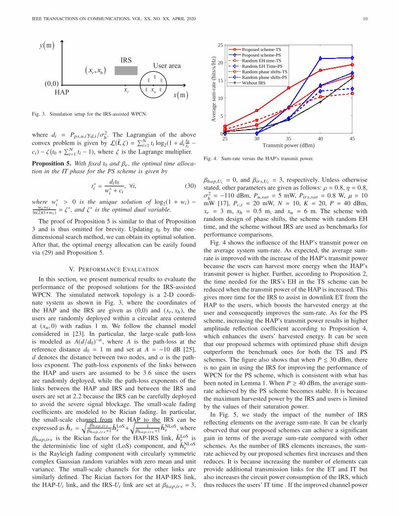
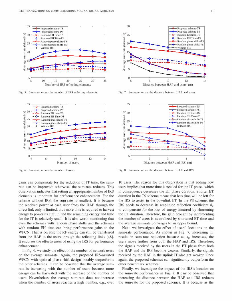
II. SYSTEM MODEL
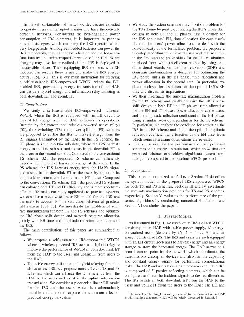
As illustrated in Fig. 1, we consider an IRS-assisted WPCN,
consisting of an HAP with stable power supply, N energy-
constrained users (denoted by Ui, i = 1, . . . , N), and an
energy-constrained IRS. The IRS and users are each equipped
with an EH circuit (rectenna) to harvest energy and an energy
storage to store the harvested energy. The HAP serves as a
central control point for the network, which coordinates the
transmissions among all devices and also has the capability
and constant energy supply for performing computational
tasks. The HAP and users have single antenna each.1 The IRS
is composed of K passive reflecting elements, which can be
configured to direct the incident signals to desired directions.
The IRS assists in both downlink ET from the HAP to the
users and uplink IT from the users to the HAP. The EH and
1The model can be straightforwardly extended to the scenario that the HAPis with multiple antennas, which will be briefly discussed in Remark 3.
IEEE TRANSACTIONS ON COMMUNICATIONS, VOL. XX, NO. XX, APRIL 2020 4
!"
#$%
&&&
'()*+,-.*/(01)* #(12*3/.42(-.*/(0340042(
iU
H
u ih
u ig
!"#$%&
'(#)"*+"#
!"#$%&*+,#($"
-,!+#,.."#
/h ig
h ih
rh
H
rg
Fig. 1. System model for an IRS-assisted WPCN.
energy/information relaying at the IRS are controlled by an
attached micro-controller.
The downlink channels from the HAP to Ui , from the
HAP to the IRS, and from the IRS to Ui are denoted
by hh,i , hr ∈ CK×1, and hHu,i
∈ C1×K , respectively. The
counterpart uplink channels are denoted by gh,i , gHr ∈ C1×K ,
and gu,i ∈ CK×1, respectively. All channels are assumed to
be quasi-static flat fading, which remain constant during one
block but may change from one block to another [23]. We
assume that the channel state information (CSI) of all links is
perfectly known.2
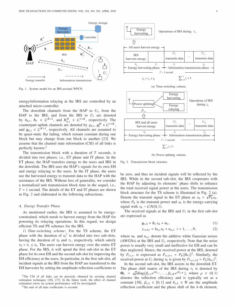
The transmission block with a duration of T seconds, is
divided into two phases, i.e., ET phase and IT phase. In the
ET phase, the HAP transfers energy to the users and IRS in
the downlink. The IRS uses the HAP’s signals for its own EH
and energy relaying to the users. In the IT phase, the users
use the harvested energy to transmit data to the HAP with the
assistance of the IRS. Without loss of generality, we consider
a normalized unit transmission block time in the sequel, i.e.,
T = 1 second. The details of the ET and IT phases are shown
in Fig. 2 and elaborated in the following subsections.
A. Energy Transfer Phase
As mentioned earlier, the IRS is assumed to be energy-
constrained, which needs to harvest energy from the HAP for
powering its relaying operations. In this regard, we design
efficient TS and PS schemes for the IRS.
1) Time-switching scheme: For the TS scheme, the ET
phase with the duration of t03 is divided into two sub-slots,
having the duration of τ0 and τ1, respectively, which satisfy
τ0 + τ1 ≤ t0. The users can harvest energy over the entire ET
phase. For the IRS, it will spend the first sub-slot in the ET
phase for its own EH and the second sub-slot for improving the
EH efficiency at the users. In particular, in the first sub-slot, all
incident signals at the IRS from the HAP are transferred to the
EH harvester by setting the amplitude reflection coefficients to
2The CSI of all links can be precisely obtained by existing channelestimation techniques [20], [37]. In the future work, the effect of channelestimation errors on system performance will be investigated.
3The unit of all time coefficients is seconds.
!"#$%&'(#)"*+,!$&-'(*"
./0&&
'(#)"*+*&"!"#$%
122&3*"#*&'(#)"*+&"!"#$%
.!45#6(+,5!&+#(!*6,**,5!&-'(*"
7U
!"#$%& $'(" "
!"#$%& $'(" "
NU
!"#$%&
'(#)"*+,!$-."#(+,/!*&/0&123&45#,!$& 6
7&*"8/!4T
! t ! "
!
N
iit
!"
#
!#
!t
Nt
(a) Time-switching scheme.
!"#$%&'(#)"*+,!$&-'(*"
./0&(!1&(22&3*"#*&
'(#)"*+&"!"#$%
.!45#6(+,5!&+#(!*6,**,5!&-'(*"
7U
!"#$%& $'(" "
!"#$%& $'(" "
NU
!"#$%&'()**)+,
-e k
!"#$%&
'(#)"*+,!$
!"#$%&
#"-(%,!$
./"#(+,0!*&01&234&
56#,!$&7t
!"#$%&'T
!
N
iit
!"
t
t Nt
(b) Power-splitting scheme.
Fig. 2. Transmission block structure.
be zero, and thus no incident signals will be reflected by the
IRS. While in the second sub-slot, the IRS cooperates with
the HAP by adjusting its elements’ phase shifts to enhance
the total received signal power at the users. The transmission
block structure for the TS scheme is illustrated in Fig. 2 (a).
Denote the transmit signal in the ET phase as xh =√
Phsh ,
where Ph is the transmit power and sh is the energy-carrying
signal with sh ∼ CN(0, 1).The received signals at the IRS and Ui in the first sub-slot
are expressed as
yr,0 = hr xh + nr, (1)
yts,0,i = hh,ixh + nu,i, i = 1, . . . , N, (2)
where nr and nu,i denote the additive white Gaussian noises
(AWGNs) at the IRS and Ui, respectively. Note that the noise
power is usually very small and ineffective for EH and can be
thus neglected. Hence, the received power at the IRS, denoted
by Pts,r , is expressed as Pts,irs = Ph | |hr | |2. Similarly, the
received power at Ui during τ0 is given by Pts,r,i,0 = Ph |hh,i |2.
In the second sub-slot, the IRS assists in the downlink ET.
The phase shift matrix of the IRS during τ1 is denoted by
denotes the reflection efficiency and is typically set as a
constant [38], βe,k ∈ [0, 1] and θe,k ∈ R are the amplitude
reflection coefficient and the phase shift of the k-th element,
IEEE TRANSACTIONS ON COMMUNICATIONS, VOL. XX, NO. XX, APRIL 2020 5
respectively. Let ve,k = e jθe,k , where |ve,k | = 1. For the
TS scheme, since the IRS only harvests energy during τ0,
all incident signals at the IRS during τ1 can be reflected
to enhance the EH efficiency, i.e., βe,k = 1, ∀k [13]. Let
Θe = diag{ve,1, . . . , ve,K }. During τ1, the received signal at
Ui for the TS scheme is given by
yts,i = (hHu,i
√ρΘehr + hh,i)xh + nu,i, i = 1, . . . , N . (3)
The received power of Ui during τ1 is then given by Pts,r,i,1 =
Ph |hHu,i
√ρΘehr + hh,i |2.
In practice, the EH circuits usually lead to a non-linear
rectification efficiency, i.e., the RF power-to-direct current
power conversion is a non-linear function with respect to
the received RF power [39], [40]. In particular, the harvested
power first improves with the increase of received power but
finally becomes saturated when the received power is high
[40]. To approximate the non-linear EH characteristics and
account for the saturation region of practical energy harvesters,
we employ a two-piece linear EH model,4 which is also widely
used in the literature, e.g., [34]-[36]. According to this model,
the harvested power is calculated as
Ph =
{
ηPr, ηPr < Psat,
Psat, otherwise,(4)
where η is the EH efficiency in the linear regime,5 Pr is the
received power, and Psat denotes the saturation power, beyond
which there will be no increase in the amount of the harvested
power. Therefore, the harvested energy at the IRS and Ui can
be obtained as
Ets,irs = min{ηPts,irs, Pirs,sat }τ0, (5)
Ets,u,i = min{ηPts,r,i,0, Pu,i,sat }τ0+min{ηPts,r,i,1, Pu,i,sat }τ1, i = 1, . . . , N, (6)
where Pirs,sat and Pu,i,sat represent the saturation power of
the IRS and Ui, respectively.
2) Power-splitting scheme: Different from the TS scheme,
the dedicated EH time is not required in the PS scheme and the
IRS harvests energy from the HAP by adjusting the amplitude
reflection coefficients (βe,k, ∀k)6, as illustrated in Fig. 2 (b).
To be specific, only a part of the HAP’s energy signals is fed
into the IRS’s EH unit for harvesting and the remaining part
is reflected by the IRS to enhance the amount of harvested
energy at the users.
4There also exist other EH models, e.g., the logistic function based non-linear EH model [39] and the multi-piece linear EH model [41]. However, it isnoted that the two-piece linear EH model is sufficiently accurate for modelingthe behavior of practical EH circuits. Compared to the logistic function basednon-linear EH model, the piece-wise linear EH model is mathematicallyappealing and easily tractable. In addition, the results obtained from the two-piece linear EH model can be straightforwardly extended to the multi-piecelinear EH model.
5In practice, the EH efficiency in this regime is not strictly linear. However,as mentioned in Footnote 4, assuming a constant η is still sufficiently accuratefor modeling the practical EH circuits.
6Adjusting the reflection coefficient can be achieved by using electronicdevices such as positive-intrinsic-negative (PIN) diodes, field-effect transis-tors (FET), micro-electromechanical system (MEMS) switches, and variableresistor loads [13], [42].
It is assumed that all the amplitude reflection coefficients
of the IRS elements have the same value, i.e. βe,k = βe, ∀k.7
The received signal at Ui in the ET phase for the PS scheme
is thus given by
yps,i = (hHu,i
√ρβeΘehr + hh,i)xh + nu,i, i = 1, . . . , N . (7)
The harvested energy of the IRS and Ui for the PS scheme is
In the IT phase, the users transmit information to the HAP
via time division multiple access, using the harvested energy
in the ET phase. Denote the duration of IT for Ui as ti . Let
su,i be the information-carrying signal of Ui with unit power.
The transmit signal of Ui during ti is then expressed as xu,i =√
Pu,isu,i , where Pu,i is Ui’s transmit power and satisfies
Pu,iti + Pc,iti ≤ E f ,u,i, f = {ts, ps}, (10)
with Pc,i being the circuit power consumption of Ui. As
the amplitude reflection coefficients are set to be the same,
the IRS’s circuit power consumption is mainly caused by
performing each element’s phase shifting [16], [17]. The
other power consumptions, such as powering the EH circuit
and signaling overhead, can be considered to be negligible
[27], [32], [43]. By denoting the power consumption of each
element as µ, the circuit power consumption of the IRS is
thus expressed as Kµ. To power its operations, IRS needs to
harvest sufficient energy in the ET phase. We assume that all
the harvested energy stored in the energy storage can be used
to power the IRS’ circuits, the following constraints are thus
held:
Kµ(τ1 +N∑
i=1
ti) ≤ Ets,irs, (11)
Kµ(t0 +N∑
i=1
ti) ≤ Eps,irs, (12)
for TS and PS schemes, respectively. Note that the power
consumption of the IRS in the first sub-slot of the TS scheme
is neglected because the IRS’s power consumption is mainly
determined by the reflection operation [16], [17], which do
not take place during τ0.
Denote the phase shift of the k-th element for Ui’s IT as
θd,i,k ∈ R. Then, the phase shift matrix during ti is denoted by
Θd,i , where Θd,i =√ρdiag{vd,i,1, . . . , vd,i,K }, vd,i,k = e jθd, i,k ,
and |vd,i.k | = 1. Note that we have set the amplitude reflection
coefficients to be 1 to maximize the signal reflection in the IT
7In practice, the elements can have different amplitude reflection coef-ficients. However, the setting will greatly complicate the circuit design ofthe IRS as different circuits should be integrated to control the amplitudereflection coefficient and phase shift independently at each element [13], [42].To guarantee the operations of the self-sustainable IRS, we should simplify itscircuit design to reduce its circuit power consumption, which can be achievedby setting all amplitude reflection coefficients to be the same.
IEEE TRANSACTIONS ON COMMUNICATIONS, VOL. XX, NO. XX, APRIL 2020 6
phase [13]. The received signal at the HAP from Ui, denoted
by yh,i , is thus given by
yh,i = (gHr Θd,igu,i + gh,i)√
Pu,isu,i + nh, (13)
where nh ∼ CN(0, σ2h) is the AWGN at the HAP. The SNR
at the HAP during ti, denoted by γi , is expressed as γi =Pu, i |gH
r Θd, igu, i+gh, i |2σ2h
. The achievable rate from Ui to the HAP
in bits/second/Hz is then formulated as
Ri = ti log2
(
1 +Pu,i |gHr Θd,igu,i + gh,i |2
σ2h
)
. (14)
III. SUM-RATE MAXIMIZATION FOR THE TS SCHEME
In this section, we aim to maximize the system sum-rate
by jointly optimizing the phase shift design at the IRS in
both ET and IT phases, time scheduling of the network, and
power allocation at the users. The constraints for the TS
At the optimal solution, the amplitude reflection coefficient
must be set to its upper-bound to maximize the amount of
reflected power from the IRS. Therefore, according to (37),
β∗e is calculated as β∗e =√
1 − Kµ/(ηPh | |hr | |2t∗0), where
max{ Kµ
ηPh | |hr | |2 ,Kµ
Pir s,sat} < t∗
0< 1 according to (36) and (38).
This thus proves Proposition 4.
REFERENCES
[1] Cisco edge-to-enterprise IoT analyt-ics for electric utilities. Available Online:https://www.cisco.com/c/en/us/solutions/collateral\/data-center-virtualization/big-data/solution-overview-c22-740248.html,Feb. 2018.
[2] X. Lu, P. Wang, D. Niyato, D. I. Kim, and Z. Han, “Wireless networkswith RF energy harvesting: A contemporary survey,” IEEE Commun.
Surv. Tut., vol. 17, no. 2, pp. 757-789, Secondquarter 2015.[3] H. Ju and R. Zhang, “Throughput maximization in wireless powered
communication networks,” IEEE Trans. Wireless Commun., vol. 13, no.1, pp. 418-428, Jan. 2014.
[4] P. Ramezani and A. Jamalipour, “Toward the evolution of wirelesspowered communication networks for the future Internet of Things,” IEEENetwork, vol. 31, no. 6, pp. 62-69, Nov./Dec. 2017.
[5] H. Chen, Y. Li, J. L. Rebelatto, B. F. Uchoa-Filho, and B.Vucetic, “Harvest-then-cooperate: Wireless-powered cooperative commu-nications,” IEEE Trans. Signal Process., vol. 63, no. 7, pp. 1700-1711,Apr., 2015.
[6] H. Ju and R. Zhang, “Uer cooperation in wireless powered communicationnetworks,” in Proc. IEEE GLOBECOM, Austin, TX, USA, Dec. 2014,pp. 1430-1435.
[7] Y. Zeng, H. Chen, and R. Zhang, “Bidirectional wireless information andpower transfer with a helping relay,“ IEEE Commun. Letters, vol. 20, no.5, pp. 862-865, May 2016.
[8] C. Zhong, H. A. Suraweera, G. Zheng, I. Krikidis, and Z. Zhang,“Wireless information and power transfer with full duplex relaying,“ IEEE
Trans. Commun., vol. 62, no. 10, pp. 3447-3461, Oct. 2014.
[9] B. Lyu, D. T. Hoang, and Z. Yang, “User Cooperation in wireless-poweredbackscatter communication networks,” IEEE Wireless Commun. Lett., vol.8, no. 2, pp. 632-635, Apr. 2019.
[10] S. H. Kim and D. I. Kim, “Hybrid backscatter communication forwireless-powered heterogeneous networks,” IEEE Trans. Wireless Com-
mmun., vol. 16, no. 10, pp. 6557-6570, Oct. 2017.
[11] S. Gong, X. Huang, J. Xu, W. Liu, P. Wang, and D. Niyato, “Backscatterrelay communications powered by wireless energy beamforming,” IEEE
Trans. Commun., vol. 66, no. 7, pp. 3187-3200, July 2018.
[12] V. Liu, A. Parks, V. Talla, S. Gollakota, D. Wetherall, and J. R. Smith,“Ambient backscatter: Wireless communication out of thin air,” in Proc.SIGCOMM, pp. 39-50, Hong Kong, Aug. 2013.
[13] Q. Wu and R. Zhang, “Towards smart and reconfigurable environment:Intelligent reflecting surface aided wireless network,” IEEE Commun.
Mag., vol. 58, no. 1. pp 106-112, Jan. 2020.
[14] S. Gong et al. “Towards smart radio environment for wireless communi-cations via intelligent reflecting surfaces: A comprehensive survey,” IEEECommun. Surveys Tuts.,, doi: 10.1109/COMST.2020.3004197, 2020.
[15] M. D. Renzo et al., “Smart radio environments empowered by recon-figurable AI meta-surfaces: An idea whosetime has come,” EURASIP J.
Wireless Commun. Netw., vol. 129, pp. 1-20, May 2019.
[16] C. Huang, G. C. Alexandropoulos, A. Zappone, M. Debbah, and C.Yuen, “Energy efficient multi-user MISO communication using low reso-lution large intelligent surfaces,” in Proc. IEEE GLOBECOM Workshops,Abu Dhabi, United Arab Emirates, 2018, pp. 1-6.
[17] C. Huang, A. Zappone, G. C. Alexandropoulos, M. Debbah, andC. Yuen, “Reconfigurable intelligent surfaces for energy efficiency inwireless communication,” IEEE Trans. Wireless Commun., vol. 18, no.8, pp. 4157-4170, Jun. 2019.
[18] A. Taha, M. Alrabeiah, and A. Alkhateeb, “Enabling large intelligentsurfaces with compressive sensing and deep learning,” Available Online:https://arxiv.org/pdf/1904.10136.pdf, Apr. 2019.
[19] C. Huang, R. Mo and C. Yuen, “Reconfigurable intelligent surfaceassisted multiuser MISO systems exploiting deep reinforcement learning,”IEEE J. Sel. Areas Commun., vol. 38, no. 8, pp. 1839-1850, Aug. 2020.
[20] D. Mishra and H. Johansson, “Channel estimation and low-complexitybeamforming design for passive intelligent surface assisted MISO wire-less energy transfer,” in Proc. IEEE ICASSP, Brighton, UK, May 2019,pp. 46594663.
[21] X. Yu, D. Xu, and R. Schober, “MISO wireless communication systemsvia intelligent reflecting surfaces,” in Proc. IEEE/CIC ICCC, Changchun,China, Aug. 2019, pp. 735740.
[22] Q. Wu and R. Zhang, “Intelligent reflecting surface enhanced wirelessnetwork via joint active and passive beamforming,” IEEE Trans. Wireless
Commun., vol. 18, no. 11, pp. 5394-5409, Nov. 2019.
[23] Q. Wu and R. Zhang, “Weighted sum power maximization for intelligentreflecting surface aided SWIPT,” IEEE Wireless Commun. Lett., vol. 9,no. 5, pp. 586-590, May 2020.
[24] C. Pan, H. Ren, K. Wang, M. Elkashlan, A. Nallanathan, J. Wang, andL. Hanzo “Intelligent reflecting surface aided MIMO broadcasting forsimultaneous wireless information and power transfer,” IEEE J. Sel. Area.Commun., vol. 38, no. 8, pp. 1719-1734, Aug. 2020.
[25] Z. Chu, W. Hao, P. Xiao, and J. Shi, “Intelligent reflect surface aidedmulti-antenna secure transmission,” IEEE Wireless Commun. Lett., vol.9, no. 1, pp. 108-112, Jan. 2020.
[26] C. Guo, Y. Cui, F. Yang, and L. Ding, “Outage probability analysisand minimization in intelligent reflecting surface-assisted MISO systems,”IEEE Commun. Lett., vol. 24, no. 7, 1563-1567, July 2020.
[27] Y. Zou, Y. Liu, S. Gong, W. Cheng, D. T. Hoang, and D. Niyato, “Jointenergy beamforming and optimization for intelligent reflecting surfaceenhanced communications,” in Proc. WCNC Workshops, Seoul, SouthKorea, May 2020, pp. 1-6.
[28] J. Zhao and Y. Liu, “A survey of intelligent reflecting surfaces(IRSs): Towards 6G wireless communication networks,” Available Online:https://arxiv.org/pdf/1907.04789.pdf, Nov. 2019.
[29] B. Lyu, D. T. Hoang, S. Gong, and Z. Yang, “Intelligent reflectingsurface assisted wireless powered communication networks,” in Proc.
WCNC Workshops, Seoul, South Korea, May 2020, pp. 1-6.
[30] Y. Zheng, S. Bi, Y. J. Zhang, Z. Quan, and H. Wang, “Intelligentreflecting surface enhanced user cooperation in wireless powered com-
[31] C. Huang et al., “Holographic MIMO surfaces for 6G wireless networks:Opportunities, challenges, and trends,” IEEE Wireless Commun. Mag.,doi:10.1109/MWC.001.1900534, 2020.
[32] A. A. Nasir, X. Zhou, S. Durrani, and R. A. Kennedy, “Relayingprotocols for wireless energy harvesting and information processing,”IEEE Trans. Wireless Commun., vol. 12, no. 7, pp. 3622-3636, Jul. 2013.
[33] P. N. Alevizos and A. Bletsas, “Sensitive and Nonlinear Far-Field RFEnergy Harvesting in Wireless Communications,” IEEE Trans. Wireless
Commun., vol. 17, no. 6, pp. 3670-3685, Jun. 2018.[34] Y. Dong, M. J. Hossain, and J. Cheng, “Performance of wireless powered
amplify and forward relaying over Nakagami-m fading channels withnonlinear energy harvester,” IEEE Commun. Lett., vol. 20, no. 4, pp.672-675, Apr. 2016.
[35] A. El Shafie, D. Niyato, and N. Al-Dhahir, “Security of an ordered-based distributive jamming scheme,” IEEE Commun. Lett. vol. 21 no. 1pp. 72-75 Jan. 2017.
[36] S. Pejoski, Z. Hadzi-Velkov, and R. Schober, “Optimal power and timeallocation for WPCNs with piece-wise linear EH model,” IEEE WirelessCommun. Lett., vol. 7, no. 3, pp. 364-367, June 2018.
[37] Z. Wang, L. Liu, and S. Cui, “Channel estimation for intelligent re-flecting surface assisted multiuser communications,” Proc. WCNC, Seoul,South Korea, May 2020, pp. 1-6.
[38] Y. Gao et al., “Reconfigurable intelligent surface for MISO systems withproportional rate constraints,” Proc. ICC, Dublin, Ireland, June 2020, pp.1-7.
[39] E. Boshkovska et al., “Practical non-linear energy harvesting model andresource allocation for SWIPT systems,” IEEE Commun. Lett., vol. 19,no. 12, pp. 2082-2085, Dec. 2015.
[40] D. Mishra and G. C. Alexandropoulos, “Transmit precoding and receivepower splitting for harvested power maximization in MIMO SWIPTsystems,” IEEE Trans. Green Commun. Netw., vol. 2, no. 3, pp. 774-786, Sept. 2018.
[41] C. Lu, L. Shi, and Y. Ye, “Maximum throughput of TS/PS scheme inan AF relaying network with non-linear energy harvester,” IEEE Access,vol. 6, pp. 26617-26625, 2018.
[42] H. Yang et al., “Design of resistor-loaded reflectarray elements for bothamplitude and phase control,” IEEE Antennas Wireless Propag. Lett.,vol. 16, pp. 11591162, 2017.
[43] S. Hu, Z. Wei, Y. Cai, D. W. K. Ng, and J. Yuan, “Sum-rate maximiza-tion for multiuser MISO downlink systems with self-sustainable IRS,”Available Online: https://arxiv.org/pdf/2005.11663.pdf, May 2020.
[44] Z. Q. Luo, W.-K. Ma, A. M.-C. So, Y. Ye, and S. Zhang, “Semidefiniterelaxation of quadratic optimization problems,” IEEE Signal Process.,vol. 27, no. 3, pp. 20-34, May 2010.
[45] S. Boyd and L. Vandenberghe, Convex Optimization. Cambridge Uni-versity Press, 2004.
[46] Michael Grant et al., “CVX: Matlab software for disciplined convexprogramming,” Available Online: http://cvxr.com/cvx, September 2013.
[47] A. M.-C. So, J. Zhang, and Y. Ye, “On approximating complex quadraticoptimization problems via semidefinite programming relaxations,” Math-ematical Programming, vol. 110, no. 1, pp. 93110, Jun. 2007.
[48] V. Arun et al., “RFocus: Practical beamforming for small devices”.Available Online: https://arxiv.org/pdf/1912.07794.pdf, May 2019.


![IEEE TRANSACTIONS ON NEURAL SYSTEMS & …IEEE TRANSACTIONS ON NEURAL SYSTEMS & REHABILITATION ENGINEERING, VOL. XX, NO. XX, XXXXXX 2 based technologies [21], [22], have the benefit](https://static.documents.pub/doc/80x56/5fb85007e75bf356042dcf7c/ieee-transactions-on-neural-systems-ieee-transactions-on-neural-systems-.jpg)


