IEEE TRANSACTIONS ON COMPUTER-AIDED DESIGN OF INTEGRATED CIRCUITS AND SYSTEMS, VOL. 31, NO. 9, SEPTEMBER 2012 1417 X-Canceling MISR Architectures for Output Response Compaction With Unknown Values Joon-Sung Yang, Member, IEEE, and Nur A. Touba, Fellow, IEEE Abstract —In this paper, an X-tolerant multiple-input signature register (MISR) compaction methodology that compacts output responses containing unknown X values is described. Each bit of the MISR signature is expressed as a linear combination in terms of Xs by symbolic simulation. Linearly dependent combinations of the signature bits are identified with Gaussian elimination and XORed to remove X values and yield deterministic values. Two X-canceling MISR architectures are proposed and analyzed with industrial designs. This paper also shows the correlation between the estimated result based on idealized modeling and the actual data for real circuits for error coverage, hardware overhead, and other metrics. Experimental results indicate that high error coverage can be achieved with X-canceling MISR configurations and it highly correlates with actual results. Index Terms—Gaussian elimination, output response com- paction, symbolic simulation, X-canceling MISR. I. Introduction S CAN TEST is a well-established design-for-testability (DFT) technique for digital circuits. With smaller feature sizes, the complexity of integrated circuits is significantly increasing. Growing design size and complexity results in longer testing times and exploding test vector volume. To alleviate the issues, test data compression methods are used. Both test stimulus compression and test response compaction are needed. Unknown X values cause issues in compacting output streams for test-response compaction as well as built- in self-test. X s arise from things such as uninitialized memory elements, nonscannable flip-flops, analog blocks, bus con- tention, floating tri-states, and other sources. Because X values that propagate indirectly or directly to the output response compactor will corrupt the signature making it unknown, X values can directly impact fault coverage [7]. A number of schemes have been developed to deal with the problem of X s in the output response. One way of controlling X s is to modify the circuit-under-test (CUT) so that it does not generate X values. This approach is called X-bounding Manuscript received July 20, 2011; revised October 2, 2011 and December 22, 2011; accepted February 21, 2012. Date of current version August 22, 2012. This work was supported in part by the National Science Foundation, under Grant CCF-0916837. This paper was recommended by Associate Editor J. L. Dworak. J.-S. Yang is with SungKyunKwan University, Suwon-si, Gyeonggi-Do 440- 746, Korea (e-mail: [email protected]). N. A. Touba is with the Computer Engineering Research Center, Department of Electrical and Computer Engineering, University of Texas, Austin, TX 78712 USA (e-mail: [email protected]). Color versions of one or more of the figures in this paper are available online at http://ieeexplore.ieee.org. Digital Object Identifier 10.1109/TCAD.2012.2193579 or X-blocking and requires adding DFT logic to prevent X -value propagation to scan cells [20]–[22]. In this method, X sources are forced to 0 (0-control point ) or 1 (1-control point ). However, since this method involves the modification of CUT, the inherent problems of the method are the increase of design area and the potential timing issues. Another approach, which does not require modifying the CUT, is X-masking that masks out X s at the input to the output response compactor. This adds a blocking logic to the com- pactor and requires masking signals. Masking signals are transferred through tester channels and they are used to specify which scan chain outputs should be masked during which clock cycles. Many schemes for X -masking hardware design and mask control data compression have been developed [1]–[3], [11]–[14], [17], [19], [23]–[26]. In many cases, the resolution of the masking is reduced in order to keep the amount of mask data at reasonable levels (e.g., an entire scan chain or an entire scan slice may be masked). This may result in some non-X values also becoming masked out that reduces observability and may impact the coverage, particularly, for unmodeled faults. A third approach is to design an X -tolerant compactor that can compact an output stream that contains X s without the need for X-masking. X -tolerant compactors have been developed based on linear combinational compactors [8], [10], [15] that are mainly based on the application of system- atic linear codes. Convolutional compactors [12] and circular registers [14] can tolerate a certain amount of X values. Although multiple-input signature registers (MISRs) are the most efficient for compacting output streams without X s, they present difficulties when X s are present because even a single X can corrupt the MISR contents with its sequential nature in accumulating its signature [9], [16]. In this paper, a new X -tolerant scheme is introduced that re- moves X values in output streams using a MISR. It allows any number of scan chain outputs to be compacted with a conven- tional MISR of any size. This X -canceling MISR methodology can achieve arbitrarily high error coverage of scan cells that are observed in the presence of X s. X -values are eliminated by linearly dependent combinations of MISR signature bits using Gaussian elimination and XORing. Symbolic simulation helps this process to express each bit of MISR signature as a linear equation in terms of the X s. Two different X - canceling MISR architectures are presented and two state-of- art industrial designs are used for the experiments. Preliminary results were shown in [18] and [27] and a discussion of the 0278-0070/$31.00 c 2012 IEEE
Transcript
IEEE TRANSACTIONS ON COMPUTER-AIDED DESIGN OF INTEGRATED CIRCUITS AND SYSTEMS, VOL. 31, NO. 9, SEPTEMBER 2012 1417
X-Canceling MISR Architectures for OutputResponse Compaction With Unknown Values
Joon-Sung Yang, Member, IEEE, and Nur A. Touba, Fellow, IEEE
Abstract—In this paper, an X-tolerant multiple-input signatureregister (MISR) compaction methodology that compacts outputresponses containing unknown X values is described. Each bit ofthe MISR signature is expressed as a linear combination in termsof Xs by symbolic simulation. Linearly dependent combinationsof the signature bits are identified with Gaussian elimination andXORed to remove X values and yield deterministic values. TwoX-canceling MISR architectures are proposed and analyzed withindustrial designs. This paper also shows the correlation betweenthe estimated result based on idealized modeling and the actualdata for real circuits for error coverage, hardware overhead,and other metrics. Experimental results indicate that high errorcoverage can be achieved with X-canceling MISR configurationsand it highly correlates with actual results.
Index Terms—Gaussian elimination, output response com-paction, symbolic simulation, X-canceling MISR.
I. Introduction
SCAN TEST is a well-established design-for-testability(DFT) technique for digital circuits. With smaller feature
sizes, the complexity of integrated circuits is significantlyincreasing. Growing design size and complexity results inlonger testing times and exploding test vector volume. Toalleviate the issues, test data compression methods are used.Both test stimulus compression and test response compactionare needed. Unknown X values cause issues in compactingoutput streams for test-response compaction as well as built-in self-test. Xs arise from things such as uninitialized memoryelements, nonscannable flip-flops, analog blocks, bus con-tention, floating tri-states, and other sources. Because X valuesthat propagate indirectly or directly to the output responsecompactor will corrupt the signature making it unknown, Xvalues can directly impact fault coverage [7].
A number of schemes have been developed to deal with theproblem of Xs in the output response. One way of controllingXs is to modify the circuit-under-test (CUT) so that it doesnot generate X values. This approach is called X-bounding
Manuscript received July 20, 2011; revised October 2, 2011 and December22, 2011; accepted February 21, 2012. Date of current version August 22,2012. This work was supported in part by the National Science Foundation,under Grant CCF-0916837. This paper was recommended by Associate EditorJ. L. Dworak.
J.-S. Yang is with SungKyunKwan University, Suwon-si, Gyeonggi-Do 440-746, Korea (e-mail: [email protected]).
N. A. Touba is with the Computer Engineering Research Center, Departmentof Electrical and Computer Engineering, University of Texas, Austin, TX78712 USA (e-mail: [email protected]).
Color versions of one or more of the figures in this paper are availableonline at http://ieeexplore.ieee.org.
Digital Object Identifier 10.1109/TCAD.2012.2193579
or X-blocking and requires adding DFT logic to preventX-value propagation to scan cells [20]–[22]. In this method,X sources are forced to 0 (0-control point) or 1 (1-controlpoint). However, since this method involves the modificationof CUT, the inherent problems of the method are the increaseof design area and the potential timing issues.
Another approach, which does not require modifying theCUT, is X-masking that masks out Xs at the input to the outputresponse compactor. This adds a blocking logic to the com-pactor and requires masking signals. Masking signals aretransferred through tester channels and they are used to specifywhich scan chain outputs should be masked during whichclock cycles. Many schemes for X-masking hardware designand mask control data compression have been developed[1]–[3], [11]–[14], [17], [19], [23]–[26]. In many cases, theresolution of the masking is reduced in order to keep theamount of mask data at reasonable levels (e.g., an entire scanchain or an entire scan slice may be masked). This may resultin some non-X values also becoming masked out that reducesobservability and may impact the coverage, particularly, forunmodeled faults.
A third approach is to design an X-tolerant compactorthat can compact an output stream that contains Xs withoutthe need for X-masking. X-tolerant compactors have beendeveloped based on linear combinational compactors [8], [10],[15] that are mainly based on the application of system-atic linear codes. Convolutional compactors [12] and circularregisters [14] can tolerate a certain amount of X values.Although multiple-input signature registers (MISRs) are themost efficient for compacting output streams without Xs, theypresent difficulties when Xs are present because even a singleX can corrupt the MISR contents with its sequential nature inaccumulating its signature [9], [16].
In this paper, a new X-tolerant scheme is introduced that re-moves X values in output streams using a MISR. It allows anynumber of scan chain outputs to be compacted with a conven-tional MISR of any size. This X-canceling MISR methodologycan achieve arbitrarily high error coverage of scan cells thatare observed in the presence of Xs. X-values are eliminatedby linearly dependent combinations of MISR signature bitsusing Gaussian elimination and XORing. Symbolic simulationhelps this process to express each bit of MISR signatureas a linear equation in terms of the Xs. Two different X-canceling MISR architectures are presented and two state-of-art industrial designs are used for the experiments. Preliminaryresults were shown in [18] and [27] and a discussion of the
1418 IEEE TRANSACTIONS ON COMPUTER-AIDED DESIGN OF INTEGRATED CIRCUITS AND SYSTEMS, VOL. 31, NO. 9, SEPTEMBER 2012
Fig. 1. Example of symbolic simulation of 6-bit MISR.
practical issues in implementing an X-canceling method is alsogiven in this paper.
This paper is organized as follows. Section II overviews thesymbolic simulation process and the X-canceling MISR bitcombination identification process. Two X-canceling schemesare described in Section III and they are investigated withindustrial designs in Section IV. Conclusions are given inSection V.
II. Overview of Proposed X-Canceling MISR
This section gives an overview of the operation of an X-canceling MISR.
In the proposed method, the output response compaction isexpressed by symbolic simulation to represent each X in theoutput stream as a unique symbol. Each bit of the final MISRsignature is expressed in terms of the symbols that correspondto each scan cell outputs and X values. If there are more bits inthe MISR than symbols, there should be some combinations ofthe MISR signature bits that are linearly dependent in terms ofthe symbols corresponding to the Xs. Gaussian elimination isused to identify the combinations of linearly dependent bitsand they can be XORed together to cancel out Xs therebyyielding a deterministic X-free signature bit. The followingdescribed the X-canceling flow in an illustrative manner.
Assume that the output response has been captured in thescan chains after applying a test vector. As illustrated in Fig. 1,the value in each scan cell can be represented by a symbol.Through symbolic simulation, the final state of the MISR canbe expressed in terms of symbols after the output response hasbeen shifted in to the MISR. Each bit of MISR is representedby a linear equation of the scan cell symbols. For example,the final values of the top bit (M1) and the bottom bit (M6) ofMISR are X1⊕O3⊕O8⊕O13 and O2⊕X3⊕X4, respectively,where Xi denoted an X value and Oi indicates a non-X valuein scan cells.
Without loss of generality, assume all the Oi values in theoutput response are 0 so that each MISR bit is now simplyequal to the linear combination of the X values. Hence, M1 andM4 in Fig. 1 are represented as X1 and X3⊕X4, respectively.
Fig. 2. Simplified linear combinations for MISR and matrix representation.
Fig. 3. Gauss–Jordan elimination of MISR equations and X-free rows.
Fig. 2 shows the X dependence of the MISR bits and itsrepresentation in the form of a matrix. In the matrix, eachentry has a 1 if the MISR bit corresponding to the row dependson the X corresponding to the column. Since there are fourXs (X1–X4) in the output response, there are 16 possiblesignatures in a fault-free circuit. In this case, it might beproblematic to check the MISR signature whether it is oneof the valid 16 fault-free signatures.
To resolve the issue, Gauss–Jordan elimination [4] is usedin the proposed method. Gauss–Jordan elimination involvesperforming rows operations that transform a set of columnsinto an identity matrix. Using the matrix in Fig. 2, the identitymatrix is generated by Gauss–Jordan elimination and this isshown in Fig. 3. The last two rows in Fig. 3 have all 0sand this indicates combinations of MISR bits in which allthe Xs cancel out. The fifth row has all 0s and it implies thatXORing MISR bits M1, M3, and M5 generates an “X-canceled”signature bit. The X-free signature bit (M1⊕M3⊕M5) iscomposed of scan cell combinations with non-X values(O3⊕O5⊕O8⊕O10⊕O12⊕O13⊕O15⊕O17). Two X-free rowsare found in Fig. 3. The values of these X-canceled MISR bitcombinations are deterministic and can be predicted throughsimulation. Therefore, during test, they can be compared withtheir fault-free values in order to detect errors.
For an m-bit MISR, k Xs present anywhere in the outputstream can be tolerated with error-detection capability equiv-alent to using an m − k-bit MISR with no unknown values.There are four Xs and 6-bit MISR used in Fig. 1. In thiscase, the error-detection capability is equivalent to 2-bit MISRand this corresponds to the two X-free rows in Fig. 3. TheMISR is operated across many clock cycles and may spanmultiple test vectors. Xs are accumulated in the MISR andthis continues until the MISR is filled up with Xs that it
YANG AND TOUBA: X-CANCELING MISR ARCHITECTURES FOR OUTPUT RESPONSE COMPACTION 1419
Fig. 4. X’s accumulation and canceling flow.
can tolerate up to. Once the MISR fills up with Xs, theMISR signature is then processed by selectively ORing linearlydependent combinations of MISR bits in terms of the Xs togenerate X-free output response. Fig. 4 shows this flow.
The probability of aliasing is 2k/ 2m assuming all possiblesignatures are equally likely and all 2k fault-free signatures areunique. If k is 20 less than m, then the probability of aliasing is2−20, which is less than one in a million. What this illustrates isthat an m-bit MISR can quite safely compact an output streamwith up to m-20 Xs with negligible loss of error coverage.
III. X-Canceling MISR Schemes
Two X-canceling MISR schemes, their architectures, andpractical issues in implementing each scheme are describedin this section. The key difference is how the test channel isassigned to perform X-canceling.
A. Time-Multiplexing X-Canceling MISR
1) Architecture Details: One approach for generating theX-canceled combinations is to halt scan shifting wheneverthe MISR is filled up with the maximum number of Xsthat it can tolerate. This method is called time-multiplexingX-canceling MISR; it has two phases that alternate over time:1) a test-vector application phase, and 2) a signature processingphase. Fig. 5 shows the architecture for time-multiplexingX-canceling MISR.
In Fig. 5, in a test-vector application phase, there are mtester channels used to load scan vectors. After the capturecycle, the output response is shifted into an m-bit MISRthrough a phase shifter as the next test vector is loaded. Aphase shifter is placed before the MISR. The purpose of thisphase shifter is to eliminate shift correlation among the datafeeding into the MISR (and it can also be used to performspace compaction if the MISR is smaller than the data word).This proceeds across multiple clock cycles and even multiplescan vectors until the MISR fills up with Xs. Then, the scanshifting is stopped and the second phase (i.e., a signatureprocessing phase) begins. Linearly dependent combinations ofMISR bits are computed by symbolic simulation as shownin Section II. During the signature processing phase, the mtester channels are used to generate X-canceled combinationsby selecting which of the m bits in the MISR should be XORed
together. The selective XOR network shown in Fig. 5 generatesX-canceled combinations. Once the MISR signature has beenprocessed, the MISR is reset and the test-vector applicationphase resumes. In this scheme, m tester channels are fullyutilized at all times to drive the scan vector decompressorduring the test application phase and to drive the selectiveXOR during the signature processing phase.
In this approach, few test channels are dedicated for scanvector loading and control data transfer, and a single testchannel is assigned for the output response. This leavesother tester channels for providing input stimulus; hence, thisarchitecture is very efficient for multisite testing and for otherapplications, where it is desirable to have more tester channelsfor input stimulus and fewer channels for output response.
B. Error Coverage, Hardware Overhead, and Other Metrics
The error coverage can be estimated based on the numberof X-canceled combinations checked. Since the MISR with aprimitive polynomial has a pseudorandom property, each X-canceled combination will depend on roughly half of the scancells capturing non-X values. Therefore, if q X-canceled com-binations are checked, the error coverage will be theoreticallyequal to 1 − 2−q. If an m-bit MISR is used, it can store up tom−q Xs and can obtain a 1−2−q error coverage by checkingq linearly dependent combinations of MISR signature bitsobtained via Gauss–Jordan elimination. In Fig. 3, 6-bit MISR(m = 6) is used and two X-canceled combinations (q = 2)are identified by Gauss–Jordan elimination. Hence, four Xs(m − q = 4, where m = 4 and q = 2) are tolerated. In thisexample, because two X-canceled combinations are checked,the error coverage equals to 1 − 2−2 = 75%. Note that highererror coverage can be achieved by having more X-canceledcombinations. Table I shows the theoretical error coveragewith q X-canceled combinations.
1420 IEEE TRANSACTIONS ON COMPUTER-AIDED DESIGN OF INTEGRATED CIRCUITS AND SYSTEMS, VOL. 31, NO. 9, SEPTEMBER 2012
As mentioned in the previous section, the scan shifting ishalted for the signature processing phase. This means thatadditional testing time is required to generate the X-canceledcombinations. The number of signature processing phasesthat are required depend on the X density (percentage ofoutput response bits that are Xs), MISR size, and target errorcoverage. The following shows how the additional testing timeis estimated with given constraints:
Constraints :
n scan chains, m-bit MISR, x% X-density, and
1 − 2−q target error coverage.
Based on the given information, assuming a Gaussian Xdistribution, there would be n ∗ x Xs in one scan slice. Sincethe target error coverage is 1−2−q, q X-canceled combinationsneed to be checked. The MISR can tolerate up to m − q Xsto achieve the target test coverage. It takes (m − q)/(n ∗ x)cycles to fill up the MISR with m−q Xs. Hence, the signatureneeds to be processed at every (m − q)/(n ∗ x) cycles. In thesignature processing phase, q cycles are needed to provide thecontrol data for generating the q X-canceled combinations.Therefore, if the total number of cycles needed to apply thetest patterns without stopping scan shifting is c, then thenumber of additional cycles added for canceling out the Xsis [c/(m − q)/(n ∗ x)] ∗ q. Hence, the total testing time andnormalized testing time with respect to the testing time withno compaction is equal to
Total testing time = c + [(c∗n∗x∗q)/(m − q)] cycles
Normalized total testing time = 1 + [(n∗x∗q)/(m − q)].
Fig. 6 shows the normalized total testing time with differentMISR sizes when 100 scan chains and 93.75% target coverageconstraints are given. As can be seen, the normalized testingtime decreases with a larger MISR and settles very close to 1.
In Table II, the amount of output response compressionwith 256-bit MISR that is obtained for output streams withdifferent numbers of scan chains and percentages of Xs areshown. The first two columns show the percentages of Xsin the output stream and the number of scan chains. One ofthe major advantages of the proposed method is that the errorcoverage does not depend on the number of Xs in a scan slice.It depends only on the number of X-canceled combinations(q). The proposed method is extremely efficient when the X-density is low.
In this scheme, the same tester channels are used for bothtest vector decompression and MISR signature processing viatime multiplexing. Hence, no additional control tester channelsare needed other than one channel to stop and resume MISRoperation. For the output response, a single tester channel canbe used for transferring the X-canceled bits. The requirementscan thus be summarized as follows:
Input tester channel : Decompressor channel + 1
Output tester channel : 1.
Note that, while the test time goes up, only one testerchannel is needed for the output response; so all the other tester
TABLE II
Response Compression With Different Numbers of Scan Chains
Fig. 6. Normalized Test Time with Different MISR Size.
channels could be used for providing test stimulus therebypermitting the use of more scan chains and thereby loweringtotal testing time (c). This actually results in a lower overalltesting time.
The required hardware overhead to implement this methodis mainly determined by XOR gates for a phase shifter and aselective XOR block. Hence, when there are n scan chains withf fanouts for a phase shifter and m-bit MISR, the hardwarerequirement can be roughly expressed as follows:
Hardware overhead :[n ∗ f + (m − 1)] two input
XOR gates and one m-bit MISR.
C. Shadow Register X-Canceling MISR
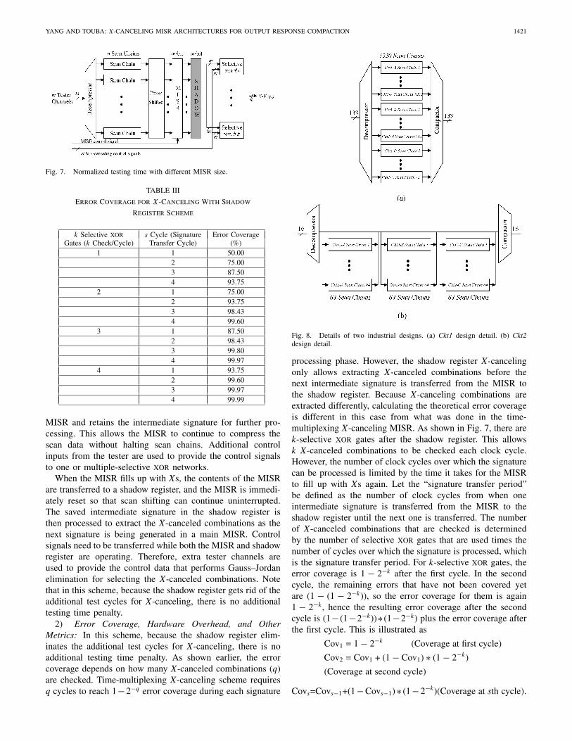
For some designs, there could be some complications inusing the time-multiplexing X-canceling MISR. It is requiredto pause the scan load or unload operation during the pro-cessing of MISR signature and this requires the ability toretain the values in the scan cells. It might be difficult tovalidate or debug patterns if the cycle count of each load orunload procedure is different; it may also be preferable to havemore output response channels to aid in debug and diagnosis.Shadow register X-canceling MISR method is presented if it isnot desirable to halt scan shifting to process the intermediateMISR signatures.
1) Architecture Details: Fig. 7 shows the shadow regis-ter X-canceling architecture. There are few differences suchas a shadow register, input tester channels, and selectiveXOR networks from the time-multiplexing X-canceling MISRarchitecture. The shadow register is placed after the main
YANG AND TOUBA: X-CANCELING MISR ARCHITECTURES FOR OUTPUT RESPONSE COMPACTION 1421
Fig. 7. Normalized testing time with different MISR size.
TABLE III
Error Coverage for X-Canceling With Shadow
Register Scheme
k Selective xor s Cycle (Signature Error CoverageGates (k Check/Cycle) Transfer Cycle) (%)
1 1 50.002 75.003 87.504 93.75
2 1 75.002 93.753 98.434 99.60
3 1 87.502 98.433 99.804 99.97
4 1 93.752 99.603 99.974 99.99
MISR and retains the intermediate signature for further pro-cessing. This allows the MISR to continue to compress thescan data without halting scan chains. Additional controlinputs from the tester are used to provide the control signalsto one or multiple-selective XOR networks.
When the MISR fills up with Xs, the contents of the MISRare transferred to a shadow register, and the MISR is immedi-ately reset so that scan shifting can continue uninterrupted.The saved intermediate signature in the shadow register isthen processed to extract the X-canceled combinations as thenext signature is being generated in a main MISR. Controlsignals need to be transferred while both the MISR and shadowregister are operating. Therefore, extra tester channels areused to provide the control data that performs Gauss–Jordanelimination for selecting the X-canceled combinations. Notethat in this scheme, because the shadow register gets rid of theadditional test cycles for X-canceling, there is no additionaltesting time penalty.
2) Error Coverage, Hardware Overhead, and OtherMetrics: In this scheme, because the shadow register elim-inates the additional test cycles for X-canceling, there is noadditional testing time penalty. As shown earlier, the errorcoverage depends on how many X-canceled combinations (q)are checked. Time-multiplexing X-canceling scheme requiresq cycles to reach 1−2−q error coverage during each signature
Fig. 8. Details of two industrial designs. (a) Ckt1 design detail. (b) Ckt2design detail.
processing phase. However, the shadow register X-cancelingonly allows extracting X-canceled combinations before thenext intermediate signature is transferred from the MISR tothe shadow register. Because X-canceling combinations areextracted differently, calculating the theoretical error coverageis different in this case from what was done in the time-multiplexing X-canceling MISR. As shown in Fig. 7, there arek-selective XOR gates after the shadow register. This allowsk X-canceled combinations to be checked each clock cycle.However, the number of clock cycles over which the signaturecan be processed is limited by the time it takes for the MISRto fill up with Xs again. Let the “signature transfer period”be defined as the number of clock cycles from when oneintermediate signature is transferred from the MISR to theshadow register until the next one is transferred. The numberof X-canceled combinations that are checked is determinedby the number of selective XOR gates that are used times thenumber of cycles over which the signature is processed, whichis the signature transfer period. For k-selective XOR gates, theerror coverage is 1 − 2−k after the first cycle. In the secondcycle, the remaining errors that have not been covered yetare (1 − (1 − 2−k)), so the error coverage for them is again1 − 2−k, hence the resulting error coverage after the secondcycle is (1− (1−2−k))∗ (1−2−k) plus the error coverage afterthe first cycle. This is illustrated as
Cov1 = 1 − 2−k (Coverage at first cycle)
Cov2 = Cov1 + (1 − Cov1) ∗ (1 − 2−k)
(Coverage at second cycle)
Covs=Covs−1+(1−Covs−1)∗ (1−2−k)(Coverage at sth cycle).
1422 IEEE TRANSACTIONS ON COMPUTER-AIDED DESIGN OF INTEGRATED CIRCUITS AND SYSTEMS, VOL. 31, NO. 9, SEPTEMBER 2012
TABLE IV
Time-Multiplexing X-Canceling MISR Method: Testability Comparison of Proposed Methods With Conventional Implementation
Tester Channel No. of Estimated Test Actual Test Estimated ActualCircuit Compactor xors Time Time Error Error
Table III shows the error coverage for different values of kand the signature transfer period, s.
For example, assume that the signatures are transferred froma MISR to a shadow register every three cycles (s = 3) andthere are two selective XOR gates (k = 2) after a shadow regis-ter in Fig. 7. Hence, the error coverage for each cycle can befound as Cov1 = 1−2−2 = 75%, Cov2 = 0.75+0.75∗(1−2−2) =93.75%, and Cov3 = 0.9375 + 0.9375 ∗ (1 − 2−2) = 98.43%.
Unlike time-multiplexing X-canceling, the shadow regis-ter X-canceling dedicates tester channels to provide con-trol signals to the selective XORs. Hence, if k XOR gates(k checks/cycle) are used, m ∗ k input tester channels areneeded for driving them, where m is the size of the MISR;one input tester channel needs to be assigned to controlwhen the MISR signature is transferred to the shadow reg-ister and reset. For the output response, k tester channelsare required. The requirements can thus be summarized asfollows:
Input tester channels : Decompressor channels +
(MISR−size ∗ checks/cycle) + 1
Output tester channels : Checks/cycle.
Shadow register X-canceling MISR requires more selec-tive XOR networks and additional one m-bit shadow register.
Hence, when there are n scan chains with f fanouts and m-bitMISR, the hardware requirement can be roughly expressed asfollows:
Hardware overhead : [n∗f + k∗(m − 1)] two input
xor gates and two m-bit MISR.
IV. Analysis of Proposed Methods With
Intel Designs
Two industrial designs from Intel were analyzed in detailfor the experiments. Fig. 8 shows two designs with scan chaininformation and tester channels for inputs and outputs.
Fig. 8(a) shows Ckt1 and it has 133 input and output testerchannels, respectively; 133 inputs are expanded into 1330 scanchains and it achieves a 10x compression [6]. Ckt1 has threesubblocks (A, B, and C) and they have 1050, 203, and 75 scanchains, respectively; 62, 38, and 31 output tester channels areassigned to Ckt1-A, Ckt1-B, and Ckt1-C, respectively, and twooutput channels are used for bypass.
Ckt2 is shown in Fig. 8(b). Ckt2 has relatively fewer testchannels than Ckt1 and it has 16 input and output testerchannels. There are three partitions (A, B, and C) in the designthat are connected in a daisy chain manner. Ckt2-A, Ckt2-B,and Ckt2-C all have 64 scan chains. Ckt2 has a 4x compression
YANG AND TOUBA: X-CANCELING MISR ARCHITECTURES FOR OUTPUT RESPONSE COMPACTION 1423
ratio; 16 inputs are expanded to fill 64 scan chains. Each ofCkt1 and Ckt2 submodules has different X-density.
The time-multiplexing X-canceling and shadow register X-canceling schemes are analyzed and compared with X-compact[8] that is widely used. X-compact is guaranteed to be able totolerate one X per scan slice. However, for these two designs,the fault coverage dropped significantly with X-compact fromthe case where the output response was not compressed. Thedistribution of Xs in these designs was such that many scanslices had too many Xs to be efficiently compacted with X-compact. Experimental results from two X-canceling schemesare presented, respectively, and compared with X-compact.
A. Time-Multiplexing X-Canceling MISR
Table IV shows the results for time-multiplexing X-canceling. A 32-bit MISR is used for each of the three blocksin Ckt1 to compact the responses from the scan chains andto generate X-canceled combinations. The outputs of the scanchains are fed into a phase shifter before going to the MISRto reduce shift correlation [18]. The first column shows thecircuits and the second column shows the types of compactors.As shown in Section III-A, the error coverage depends onhow many X-canceled combinations (q) are checked. Resultswere generated for values of q ranging from 5 to 8. Thethird column shows the number of input and output testerchannels used. The formula for the required number of inputand output channels was given in Section III-A. The numberof two input XOR gates for hardware overhead estimation isshown in the fourth column. As described earlier, for Ckt1-A,a 32-bit MISR, where each scan chain output fans out to sevenXOR gates in a phase shifter, is used; so the number of twoinput XOR gates is 7381 (7∗1050+31). The fifth column showsthe test time for each scheme. The results are normalized withrespect to the results for X-compact. The additional testingtime for control signal transfer is also normalized and shownin the fifth column. The last column shows the error coverage.Unlike other schemes, the error coverage for an X-cancelingMISR can be estimated based on the number of X-canceledcombinations that are observed. The experimental results showwhat the theory would estimate the coverage and testing timeto be for purposes of comparison with the actual values. ForCkt2, a 64-bit MISR and a phase shifter with five fanouts perscan chain were used. Larger MISRs can hold more Xs beforeneeding to be processed, however, they also require more datato process each signature; so the net effect is that testing timeand storage is relatively constant regardless of the MISR size.The main issue with the MISR size is the number of Xs in asingle scan slice that it can handle. The MISR size should notbe smaller than the maximum number of Xs in any scan slice.
As can be seen from Table IV, the proposed method achievesan error coverage and testing time very close to that predictedby the theoretical formula. The reason for the slight deviationis that the formulas assume the MISR can stop when it takesexactly the full number of Xs values that it can hold. However,in practice, the Xs are entering the MISR in clusters scan sliceby scan slice; so if the next scan slice puts the number ofXs over the limit, the MISR signature must first be processedbefore it can compact that scan slice. This results in some extra
testing time in comparison to that predicted by the theoreticalformulas.
In comparing the results for X-canceling with X-compact,many fewer output tester channels are required while arbi-trarily higher error coverage can be achieved to whateverthe desired level is. For Ckt1, less overhead is required forX-canceling. For Ckt2, the overhead is very low for bothmethods. Time-multiplexing X-canceling does have highertesting time in this scenario because the output tester channelsthat have been reduced have not been used for providing teststimulus. Effectively, the tester bandwidth allocated for X-canceling here is less than that for X-compact.
Looking at the individual partitions, it can be seen thatCkt1-A has very low X-density, and both X-compact and X-canceling perform very well. X-canceling requires many feweroutput tester channels and less overhead with a bit more testingtime. For Ckt1-B and Ckt1-C, the X-density is over 3% inboth cases, and the error coverage provided by X-compactis low. This occurs because some scan slices have many Xs.Note that even though Ckt1-B and Ckt1-C have similar X-densities, the X-compact coverage for Ckt1-B is much lower.This is because the distribution of Xs in Ckt1-B is such thatcoverage is lost for a larger percentage of scan slices than inCkt1-C. The Xs in Ckt1-C are more clustered in fewer scanslices, so the percentage of scan slices where coverage is lostis less. X-canceling can achieve high error coverage for anydistribution of Xs, so it performs very well in terms of errorcoverage. The cost of achieving the higher error coverage isadditional testing time, but again fewer output tester channelsare required. For Ckt2, X-compact is using 32 tester channels,while X-canceling is using only 18 tester channels. If the 14tester channels that are reduced with X-canceling were to beemployed in providing test stimulus, then X-canceling wouldhave lower testing time in all cases while providing greatererror coverage.
As explained and shown in Table IV, time-multiplexingX-canceling method almost achieves the estimated errorcoverage. For the detailed analysis, different MISR sizes(21–32 bits) are chosen to show the testing time estimationcorrelation when the target error coverage is 99.2%; theerror coverage analysis with respect to different X-canceledcombinations (q = 1 ∼ q = 8) is also illustrated. Fig. 9shows results from Ckt1-A and Ckt1-C. As graphs show, theactual error coverage and the actual testing time correlates veryclosely with the estimation. Assumption in measuring testingtime is that test channels are only used for X-canceling. Inreality, because only one output channel is needed for theoutput response in this scheme, there would be extra testerchannels available and they could be used to provide teststimulus at other sites. Hence, the actual testing time can belower than the one shown in Fig. 9(a) and (c).
B. Shadow Register X-Canceling MISR
Table V shows the results from shadow register X-cancelingMISR scheme. Unlike time-multiplexing method, the controlsignals are provided via dedicated channels while scan shiftis running. X-canceled combinations are generated withoutintroducing additional testing time. Hence, the testing time
1424 IEEE TRANSACTIONS ON COMPUTER-AIDED DESIGN OF INTEGRATED CIRCUITS AND SYSTEMS, VOL. 31, NO. 9, SEPTEMBER 2012
Fig. 9. Testing time and error coverage analysis with different configurationsfor time-multiplexing X-canceling scheme. (a) Ckt1-A: Testing time analysis.(b) Ckt1-A: Error coverage analysis. (c) Ckt1-C: Testing time analysis.(d) Ckt1-C: Error coverage analysis.
is exactly same for X-compact and this method. As explainedin Section III, the error coverage differs with the numbersof checks/cycle and this is shown in the second column.In column three and four, the number of input and outputchannels and the number of two input XOR gates are calculatedby the estimation equations in Section III. The last columnshows the error coverage. The error coverage for X-cancelingcan be made arbitrarily high. In this case, improving the errorcoverage comes at the cost of requiring more checks/cycle thatrequires more input tester channels, however, the testing timeremains constant.
Fig. 10. Testing time and error coverage analysis with different configura-tions for time-multiplexing X-canceling scheme. (a) Ckt1-B: Error coverageanalysis with two checks/cycle. (b) Ckt1-B: Error coverage analysis withthree checks/cycle. (c) Ckt1-C: Error coverage analysis with two checks/cycle.(d) Ckt1-C: Error coverage analysis with three checks/cycle.
Fig. 10 shows more data with different MISR size andthe three checks/cycle for Ckt1-B and Ckt1-C (Ckt-A is notshown because the low X-density shows very good correlationresults). The target error coverage can be found in Table III.As explained, the estimated error coverage varies with respectto checks/cycle and signature transfer cycle. Fig. 10 showsincreasing error coverage with bigger MISRs because theycan tolerate more X-values and this increases the signaturetransfer cycle. For smaller MISRs, there is some correlationgap between the estimated and actual value. Because MISRsare easily filled up with Xs, the actual signature transfer cycleis shorter than estimation. As can be seen, as the MISR size
YANG AND TOUBA: X-CANCELING MISR ARCHITECTURES FOR OUTPUT RESPONSE COMPACTION 1425
TABLE V
Shadow Register X-Canceling MISR Method: Testability Comparison of Proposed Methods With Conventional Implementation
grows, the actual error coverage shows a very good correlationwith estimation.
It should be noted that the proposed methods provide gooderror coverage estimation and design requirements before thedesign stage. This would be a great help for planning X-canceling architectures and for estimating their error coverage.
C. Output Response Compression
In Table VI, the amount of output response compressionthat is obtained for output streams with Ckt1-A, B, and C,and with Ckt2-A, B, and C are shown. The results are shownwith the configurations used for Tables IV and V.
In Table VI(a), for Ckt1 and Ckt2, because the compressionratio depends on the number of X-canceled combinations (q),the compression ratio with different number of X-canceledcombinations are shown. The lower X-density is required thatreduces the number of control bits stored. The experimentalresults show that the time-multiplexing X-canceling MISRmethod achieves 17x–200x compression ratio depending ondifferent X-densities. Note that the compression ratio varieswith the number of Xs and this method can achieve a compres-sion ratio higher than 10 000x when the X-density is 0.001%[18].
In Table VI(b), the compression ratios are shown withdifferent check/cycle and different MISR size. Scan shifting is
not halted in the shadow register X-canceling method, and X-canceled combinations are generated from the shadow registerwith scan shifting. Hence, this requires more control bitscompared to the time-multiplexing X-canceling method. Thenumber of control bits is determined by the check/cycle andMISR size. This explains why the compression ratios for Ckt2-A, B, and C are the same.
D. Fault Grading Analysis
Fault grading was performed on Ckt1 to see the actualfault coverage that is achieved by the X-canceling methodsand X-compact. For each block in Ckt1, a 32-bit MISR withq = 8 configuration is used for time-multiplexing X-canceling.For shadow register X-canceling, because this adds dedicatedtester chandlers, a configuration was selected that has a similarnumber of tester channels to X-compact for a fair comparison.As its configurations, 12-bit MISR with four checks/cyclefor Ckt1-A, 19-bit MISR with two checks/cycle for Ckt1-B, and 14-bit MISR with two checks/cycle for Ckt1-C areused. This requires 268 tester channels and X-compact needs266 channels. The fault coverage for 3000 ATPG patterns isshown in Fig. 11. Without any compression, fault coverageslightly over 90% is obtained. As shown in Tables IV and V,the X-canceling MISR schemes achieve high error coveragethat translates to fault coverage, which is very close to what
1426 IEEE TRANSACTIONS ON COMPUTER-AIDED DESIGN OF INTEGRATED CIRCUITS AND SYSTEMS, VOL. 31, NO. 9, SEPTEMBER 2012
Fig. 11. Fault grading results for Ckt1 with different schemes.
is obtained without any compression. The fault coverage forX-compact, however, approaches about 86%–85%, which is2%–3% lower than the proposed methods.
V. Conclusion
The proposed X-canceling architectures showed the advan-tages in terms of their scalability and ability to systematicallyachieve high fault coverage regardless of the distribution ofXs. Because the tester requirement depends only on the totalnumber of Xs in the output response and is independent on
the design size, number of test vectors, or scan architectures,it scales well and achieves very high coverage. Two differentarchitectures can be selected based on test environments suchas tester channel availability, scan shift pause availability, andso on.
In-depth analysis showed that the proposed methods achievevery good correlation between the estimations provided in thispaper and the actual data. Hence, the proposed methods can beused in the early design stage with post-silicon for the efficientoutput response analysis. It should also be noted that theproposed methods can be incorporated with other X-handlingtechniques, such as X-masking, and others, as a hybridX-canceling method.
References
[1] C. Barnhart, V. Brunkhorst, F. Distler, O. Farnsworth, B. Keller, and B.Koenemann, “OPMISR: The foundation for compressed ATPG vectors,”in Proc. Int. Test Conf., 2001, pp. 748–757.
[2] M. C.-T. Chao, S. Wang, S. T. Chakradhar, and K.-T. Cheng, “Responseshaper: A novel technique to enhance unknown tolerance for outputresponse compaction,” in Proc. Int. Conf. Comput.-Aided Des., 2005,pp. 80–87.
[3] V. Chickermane, B. Foutz, and B. Keller, “Channel masking synthesisfor efficient on-chip test compression,” in Proc. Int. Test Conf., 2004,pp. 452–461.
[4] C. G. Cullen, Linear Algebra with Applications. Reading, MA: Addison-Wesley, 1997.
[5] R. Garg, R. Putman, and N. A. Touba, “Increasing output compactionin presence of unknowns using an X-canceling MISR with deterministicobservation,” in Proc. IEEE VLSI Test Symp., Apr.–May 2008, pp. 35–42.
[6] I. Hamzaoglu and J. H. Patel, “Reducing test application time for fullscan embedded cores,” in Proc. Dig. Papers 29th Annu. Int. Symp. FaultTolerant Comput., 1999, pp. 260–267.
[7] M. Hilscher, M. Braun, M. Richter, A. Leininger, and M. Gossel, “X-tolerant test data compaction with accelerated shift registers,” J. ElectronTest., vol. 25, nos. 4–5, pp. 247–258, Aug. 2009.
[8] S. Mitra and K. S. Kim, “X-compact: An efficient response compactionscheme,” IEEE Trans. Comput.-Aided Des., vol. 23, no. 3, pp. 421–432,Mar. 2004.
[9] S. Mitra, S. S. Lumetta, and M. Mitzenmacher, “X-tolerant signatureanalysis,” in Proc. Int. Test Conf., 2004, pp. 432–441.
[10] J. H. Patel, S. S. Lumetta, and S. M. Reddy, “Application of Saluja-Karpovsky compactors to test responses with many unknowns,” in Proc.VLSI Test Symp., 2003, pp. 107–112.
[11] I. Pomeranz, S. Kundu, and S. M. Reddy, “On output response compres-sion in the presence of unknown output values,” in Proc. Des. Automat.Conf., 2002, pp. 255–258.
[12] J. Rajiski, J. Tyszer, C. Wang, and S. M. Reddy, “Finite memorytest response compactors for embedded test applications,” IEEE Trans.Comput.-Aided Des., vol. 24, no. 4, pp. 622–634, Apr. 2005.
[13] J. Rajski J. Tyszer, G. Mrugalski, W.-T. Cheng, N. Mukherjee, and M.Kassab, “X-press compactor for 1000x reduction of test data,” in Proc.Int. Test Conf., no. 18.1. Oct. 2006, pp. 1–10.
[14] W. Rajski and J. Rajski, “Modular compactor of test responses,” in Proc.VLSI Test Symp., 2006, pp. 242–251.
[15] M. Sharma and W.-T. Cheng, “X-filter: Filtering unknowns from com-pacted test responses,” in Proc. Int. Test Conf., Nov. 2005, pp. 1–9.
[16] O. Sinanoglu and S. Almukhaizim, “X-alignment techniques for improv-ing the observability of response compactors,” in Proc. Int. Test Conf.,Nov. 2009, pp. 1–10.
[17] Y. Tang, H.-J. Wunderlich, P. Engelke, I. Polian, B. Becker, J. Scholöffel,F. Hapke, and M. Wittke, “X-masking during logic BIST and its impacton defect coverage,” IEEE Trans. VLSI, vol. 14, no. 2, pp. 193–202,Feb. 2006.
[18] N. A. Touba, “X-canceling MISR: An X-tolerant methodology forcompacting output responses with unknowns using a MISR,” in Proc.Int. Test Conf., no. 6.2. Oct. 2007, pp. 1–10.
[19] E. H. Volkerink and S. Mitra, “Response compaction with any numberof unknowns using a new LFSR architecture,” in Proc. Des. Automat.Conf., 2005, pp. 117–122.
YANG AND TOUBA: X-CANCELING MISR ARCHITECTURES FOR OUTPUT RESPONSE COMPACTION 1427
[20] L. T. Wang, C.-W. Wu, and X. Wen, VLSI Test Principles and Architec-tures. San Mateo, CA: Morgan Kaufmann, 2006.
[21] S. Wang, W. Wei, and S. T. Chakradhar, “Unknown blocking scheme forlow control data volume and high observability,” in Proc. Des., Automat.Test Eur., 2007, pp. 1–6.
[22] S. Wang, K. J. Balakrishnan, and W. Wei, “X-block: An efficient LFSRreseeding-based method to block unknowns for temporal compactors,”IEEE Trans. Comput., vol. 57, no. 7, pp. 978–989, Jul. 2008.
[23] P. Wohl, J. A. Waicukauski, and T. W. Williams, “Design of compactorsfor signature-analyzers in built-in self-test,” in Proc. Int. Test Conf.,2001, pp. 54–63.
[24] P. Wohl, J. A. Waicukauski, S. Patel, and M. B. Amin, “X-tolerant com-pression and application of scan-ATPG patterns in a BIST architecture,”in Proc. Int. Test Conf., 2003, pp. 727–736.
[25] P. Wohl, J. A. Waicukauski, and S. Patel, “Scalable selector architecturefor X-tolerant deterministic BIST,” in Proc. Des. Automat. Conf., 2004,pp. 934–939.
[26] P. Wohl, J. A. Waicukauski, F. Neuveux, and E. Gizdarski, “Fully X-tolerant, very high scan compression,” in Proc. Des. Automat. Conf.,Jun. 2010, pp. 362–367.
[27] J.-S. Yang, N. A. Touba, S.-Y. Yang, and T. M. Mak, “Industrial casestudy for X-canceling MISR,” in Proc. Int. Test Conf., no. 17.2. Nov.2009, pp. 1–10.
Joon-Sung Yang (S’05–M’09) received the B.S.degree from Yonsei University, Seoul, Korea, in2003, and the M.S. and Ph.D. degrees from theUniversity of Texas at Austin, Austin, in 2007 and2009, respectively, all in electrical and computerengineering.
After graduation, he worked for Intel Corporationfor three years. He is currently with SungKyunKwanUniversity in Korea. His current research interestsinclude very large-scale integration testing, silicondebugging, and nanometer-scale testing and design
methodologies.Dr. Yang was a recipient of the Korea Science and Engineering Foundation
Scholarship in 2005 and the Best Paper Award at the 2008 IEEE InternationalSymposium on Defect and Fault Tolerance in VLSI Systems.
Nur A. Touba (SM’05–F’09) received the B.S. de-gree from the University of Minnesota, Minneapolis,in 1990, and the M.S. and Ph.D. degrees from Stan-ford University, Stanford, CA, in 1991 and 1996,respectively, all in electrical engineering.
He is currently a Professor with the Departmentof Electrical and Computer Engineering, Universityof Texas at Austin, Austin.
Dr. Touba was a recipient of the National ScienceFoundation Early Faulty CAREER Award in 1997,and the Best Paper Award at the 2001 VLSI Test
Symposium and the 2008 Defect and Fault Tolerance Symposium. He wasa Program Chair of the 2008 International Test Conference and the GeneralChair of the 2007 Defect and Fault Tolerance Symposium. He currently is aProgram Committee Member of the Design Automation and Test in EuropeConference, the International On-Line Test Symposium, the European TestSymposium, the Asian Test Symposium, and the Defect and Fault ToleranceSymposium.