This article has been accepted for inclusion in a future issue of this journal. Content is final as presented, with the exception of pagination.
IEEE TRANSACTIONS ON CONTROL SYSTEMS TECHNOLOGY 1
Economic Model Predictive Control andApplications for Diesel Generators
Timothy Broomhead, Chris Manzie, Peter Hield, Rohan Shekhar, and Michael Brear
Abstract— When developing control systems for dieselgenerators, tuning of the controller’s parameters to achieveacceptable performance is a significant challenge, particularlywhile satisfying input, emission, and safety constraints in theface of unknown system disturbances. Robust economic modelpredictive control (EMPC) can simplify this process by directlyaddressing the generator’s objectives, while systematicallyhandling constraints in a robust way. This paper details howrobust EMPC can be implemented as the control solution fordiesel generators. To illustrate the process, two distinct generatorapplications are considered. The first application is a powertracking diesel generator, operating under emissions constraints.Such an application is found in series hybrid electric vehicles.The second application concerns diesel generators onboardsubmarines. In this application, engine speed and exhausttemperatures must be kept constant, despite significant systemdisturbances. An experimental study highlights the effectivenessof the EMPC as a solution for both applications.
Index Terms— Diesel generator, hybrid electric vehicles, modelpredictive control (MPC), robust control, submarine.
I. INTRODUCTION
D IESEL generators are found in a diverse range ofapplications, with a variety of operating objectives and
constraints. A number of control solutions, based on differ-ing underlying structures, have been proposed. Historically,these approaches have included gain scheduling PID, slidingmode control, H∞ approaches, and model predictive con-trol (MPC) [1]. A challenge common among these controlsystems is how to best tune the controller’s parameters inorder to meet the objectives. This challenge is made partic-ularly onerous in the face of unknown system disturbancesand operating constraints. The shortcomings of these exist-ing approaches have facilitated the development of advancedmodel-based techniques.
MPC is often employed in applications, where the dynamicoptimization of a plant’s economic cost must take placeand the constraints are concerned. Conventionally, MPC isincorporated as part of a hierarchy control structure, where
Manuscript received June 23, 2015; revised March 2, 2016; acceptedMay 21, 2016. Manuscript received in final form May 27, 2016. This workwas supported in part by the Elizabeth and Vernon Puzey Foundation, in partby the Defence Science Institute, in part by the Australian Defence Scienceand Technology Group, and in part by the Advanced Centre for AutomotiveResearch and Testing. Recommended by Associate Editor E. Kerrigan.
P. Hield is with the Defence Science and Technology Group, Melbourne,VIC 3207, Australia (e-mail: [email protected]).
Digital Object Identifier 10.1109/TCST.2016.2574758
a high-level, static real-time optimizer (RTO) selects operatingpoints that minimize a plant’s economic cost [2]. Based onthese operating points, an error system is formulated, and MPCis used to regulate the error, while satisfying the constraints.In the absence of plant-model mismatch, asymptotic stabilityof the MPC guarantees set point tracking [3]. The MPC istypically formulated with a positive quadratic cost. In the caseof linear systems, this choice of cost function allows the MPCoptimization to be formulated as a quadratic program (QP),and the proofs of stability are well established [4]. A challengewith this approach is that the cost function used in the onlineoptimization may no longer be representative of the trueeconomic objectives. As a result, if the set points changefrequently with respect to the plant dynamics, this approachmay result in poor economic performance. Furthermore, prac-titioners must tune controller gains to achieve acceptabletransient performance and disturbance rejection, which canrepresent a significant and time-consuming process.
Demand for improved transient response and reduced tun-ing requirements is driving the development of alternativeapproaches. One such approach is economic MPC (EMPC).In EMPC, the RTO and the MPC are combined into a singlecontroller, which uses the economic objective directly as astage cost [5]. Though improved transient performance andreduced tuning requirements drive the development of EMPC,asymptotic performance has also been shown to be at least asgood as the best steady-state operating condition achievableby the conventional MPC [6].
Theoretical frameworks for EMPC are less mature thanthat of MPC. In order to demonstrate the closed-loopstability of the optimal steady state, early EMPC formulationsused restrictive terminal point constraints, combined withthe assumptions of strong duality with the steady-stateproblem [5]. Under the assumption of strong duality, aLyapunov function can be constructed [5]. Alternatively,a dissipativity assumption can be used in the place of thestrong duality assumption [6]–[8]. The true economic costmay not fulfill the strong duality or dissipativity assumptions;however, regularization of the cost can ensure that theseassumptions are satisfied [9]. Restrictive terminal pointconstraints can be relaxed to terminal sets and correspondingterminal weights [7]. For general nonlinear systems and costs,however, these sets and corresponding terminal weights maybe challenging to compute. More critically for EMPC, infeasi-bility of the optimization problem can arise due to the changesin economic parameters or references, which may shift theoptimal steady state and, hence, the terminal set or terminalpoint.
This article has been accepted for inclusion in a future issue of this journal. Content is final as presented, with the exception of pagination.
2 IEEE TRANSACTIONS ON CONTROL SYSTEMS TECHNOLOGY
Extensions to EMPC [10]–[13] have considered similartechniques to those in tracking MPC [10], [14], [15]. Insteadof using a terminal set in the problem formulation, thesystem is required to be at a steady state by the end ofthe prediction horizon, with an offset function penalizing thedistance to the optimal steady state. Since many applicationshave a periodicity associated with them [16], [17], this steady-state requirement is relaxed to be any periodic orbit in [13].By removing the terminal set, the constraints do not dependon the optimal steady state, allowing arbitrary changes in eco-nomic parameters without losing feasibility. However, someconcessions must be made in order to guarantee the closed-loop stability. In [11], the stage cost was modified, resultingin a stage cost which no longer resembled the true economiccost, while in [10], an artificial constraint on the terminalcondition was required, constricting the terminal condition toenforce the convergence of the system. While time-varyingterminal weights can improve performance [12], this additionalconstraint may be overly restrictive. In [13], an alternativeapproach is taken to ensure stability, whereby a margin ofcontrol authority is reserved by tightening constraints towardthe end of the prediction horizon. This control authoritycan then be used to ensure convergence toward the optimalterminal condition. This approach allows the true economiccost to be used as the stage cost and does not require additionalartificial constraints.
To ensure continuous feasibility, early formulations ofEMPC assumed perfect prediction models and no unknowndisturbances. In all practical applications, this assumption isinvalid. To address this shortcoming, tube MPC approacheshave been demonstrated in EMPC; however, this approachrequires the cost to be integrated spatially over the tube [18].Stochastic EMPC approaches have been used to handleapproximate constraints [19]; however, the economic cost andsystem are limited to the linear case and the formulation resultsin the second-order cone programming problem. As with manyother robustness techniques, such as min–max MPC, theseefforts increase the computational complexity, compared withthe conventional MPC [4]. Constraint tightening is an alterna-tive robustness approach, which achieves constraint robustnesswith little to no increase in computational complexity. Firstintroduced in [20] and generalized in [21]–[23] for conven-tional MPC, constraint tightening has been shown to subsumetube MPC approaches with constant feedback gains, due toincreased regions of attraction [24]. Constraint tightening hasbeen proposed as a viable and practical robustness extensionto EMPC [13], [25].
This paper will demonstrate the use of robust EMPC [13] asa generalized control solution for diesel generator applications.Permitted by the economic formulation, cost functions thatdirectly address a generator’s economic objectives will beused, significantly reducing the tuning requirements that aretypical of MPC. Two distinct and impactful applications willbe considered. The first application is a power-tracking gen-erator, operating under emission constraints. Such a generatormay be found in a series hybrid electric vehicle. The secondapplication is a diesel generator operating in a submarineenvironment. In this application, certain engine outputs must
be kept constant, despite large periodic disturbances. Thoughthe applications differ in their economic objectives, bothconstraints and disturbances use the same underlying imple-mentation. Specifics of each application and their practicalrelevance warrant further discussion, provided in Section II.The control system proposed in [13] and its assumptions,which allow the guarantees of robustness and stability tobe made, are summarized in Section III. The validity ofthese assumptions are discussed in the context of the specificapplications in Section IV. As a result of the controller’srobustness properties, continuous constraint adherence will bedemonstrated for each application in an experimental study inSection V. The experimental study also serves to highlight theeffectiveness of the control approach in both applications.
A. Notation
The set of integers between a and b inclusive is denotedby Ia:b. The Euclidean norm of x is denoted by |x |, and|x |1 denotes the L1 norm of x . Real system states, inputs,and outputs at time k are defined as x(k), u(k), and y(k),respectively. At time step k, the prediction of the variable xat position j along the horizon is denoted by xk
j . Stacked
vectors are in bold, i.e., the stacked vector of xkj , j ∈ I0:N
is denoted by xk . The set of all class K functions is denotedby K, and the set of all class K∞ functions is denoted by K∞.The notation [ j ] = j mod P , where P is the relevant period.The ∼ operator is used to denote the Pontryagin difference.
II. DIESEL GENERATOR APPLICATIONS
A. Power Tracking Diesel Generators
Diesel generators are found as part of diesel-electricpowertrains in a wide variety of maritime [16], [26],off-road [27]–[29], and on-road [30], [31] applications. Theprevalence of diesel-electric powertrains in these applicationsis due to their increased degrees of freedom over the con-ventional powertrains. By replacing the mechanical drive-shaft with an electric one, the engine’s speed is decoupledfrom the application, and more efficient operating points canbe selected. The powertrain in series hybrid applications isaugmented with energy storage, such as supercapacitors orbatteries, allowing a further degree of freedom where therequired electrical power can be split between the generatorand the secondary power source.
A significant research focus has been in the development ofhigh-level energy management controllers for diesel-electricpowertrains. These control systems decide on the power splitbetween the generator and the secondary power source in orderto minimize fuel consumption and maintain a desired levelof energy storage. Energy management controllers often usestationary maps to represent the diesel generator [30]–[33].As such, it is often assumed that the generator moves alongthe optimal efficiency curve, which cannot be the case, due toengine dynamics. To this end, engine speed dynamics can beincorporated into the plant model [34], or the rate of change inrequested generator power can be limited [30], [31], preventinglarge deviations from the optimal efficiency curve.
This article has been accepted for inclusion in a future issue of this journal. Content is final as presented, with the exception of pagination.
BROOMHEAD et al.: EMPC AND APPLICATIONS FOR DIESEL GENERATORS 3
Comparatively, little research has been conducted to deter-mine the best control approach to ensure that the diesel genera-tor follows the energy management controller’s power request.The power request must be followed in such a way that theemission constraints are respected, and fuel consumption isminimized. The emission products of particular concern arenitrogen oxides (NOx ) and particulate matter (PM). Theseemissions are typically managed through air-path control,using variable geometry turbochargers (VGTs) and exhaustgas recirculation (EGR) as controlled inputs. After-treatmentsystems [35] may also be used to ensure that the enginesmeet emission standards. Controlling the gas path of adiesel engine for emission minimization has been thoroughlystudied [36]–[40]. However, in these studies, the additionaldegrees of freedom in the generator application are notexploited, which can further ensure continuous emission con-straint adherence. In particular, the secondary power sourcecan be relied upon during transients, if the generator isunable to meet the request [41]. This control problem hasbeen studied in [42], where an optimal control problem wasformulated to find control inputs corresponding to minimumfuel and minimum time objectives for a transient between twopower requests. Simple emission constraints are representedby a lower bound on the normalized air-to-fuel ratio λ. Arobust generator control system was developed in [43], basedon the linear parameter varying techniques. In this case,it was assumed that both the engine speed references andthe generator output references were given. The controlledinputs included injection duration and the field voltage for thegenerator; however, emissions-related actuators and constraintswere neglected and only simulation results provided.
The robust EMPC developed in [13] presents itself as anideal candidate to solve the power tracking control problem.By directly addressing the generator’s objectives, as in [42],extensive tuning may be avoided. Furthermore, the controller’sability to directly constrain system outputs can be used toenforce emission constraints, and the controller’s robustnesspermits its implementation on a diesel engine test bed.
B. Submarine Diesel Generators
Conventional submarines are propelled through water bylarge electric motors that are powered by batteries. These bat-teries are periodically charged by diesel generators. To oper-ate the diesel generators while minimizing detectability,the submarine remains several meters below the surface of thewater, drawing fresh air from a mast protruding through thewater’s surface. The diesel engine’s exhaust is released belowthe water’s surface, resulting in a static pressure head. Theexhaust’s static pressure head varies with the height of wavespassing over the submarine, with a mean of 4–5 m [44], [45].As a result, the diesel engines have a large and time-varyingexhaust back pressure.
The World Meteorological Organization has published astandard metric for wave heights over a variety of sea condi-tions, referred to as sea states. A subset of this data, extendedby the Australian Department of Defence to include the periodof waves found in oceans around Australia [46], is given
TABLE I
SEA STATES
in Table I. The significant wave height is defined as the meanpeak-to-peak wave height of the highest third of waves, sincein practice, there is a spectrum of wave heights for a given seacondition. In addition, given in Table I is the resulting peak-to-peak back pressure variation on the engine. Sea states of 6or less make up 99% of all sea conditions [45].
The effects of increasing back pressure on a turbochargedsubmarine engine are well documented [47]–[50]. The increas-ing back pressure reduces the pressure ratio across the turbine.As a result, the turbine slows, reducing the pressure in theintake manifold. This drop in intake manifold pressure leadsto a reduction in airflow through the engine, increasing theexhaust gas temperature. The heightened back pressure andreduced intake manifold pressure increase the pumping work.The speed governor responds by increasing the fuel rate,further increasing the exhaust temperature [50]. The resultingfluctuations in exhaust gas temperature have been linked toreliability issues [47], [48].
A recent study has highlighted how a conventional speedgovernor control system, based on proportion integral (PI)control, is challenged in its ability to counteract the effectsof dynamic back pressures [51]. It was concluded that whilecareful tuning of the existing controller would allow speedfluctuations to be effectively canceled out, a different controlstructure would be required in order to also eliminate exhaustgas temperature fluctuations. VGT and active generator loadcontrol are suggested as useful actuators for reducing exhausttemperature variations [26], [51]. It is not clear how addi-tional actuators can be incorporated into the existing controlstructures. Studies have previously been conducted in orderto find new methods to control the VGT and generator loadon submarines [26]. However, the ad hoc feedback controlapproach resulted in unstable engine behavior.
Since the robust EMPC proposed in [13] accounts for bothperiodic known disturbances as well as unknown disturbances,it presents a practical control solution for the submarineapplication. The controller’s economic cost function will beused to directly address engine speed and exhaust temperaturevariations, while constraints, which enforce safe generatoroperation, can be directly imposed.
III. CONTROL SYSTEM AND EXPERIMENTAL SETUP
A. Control Approach
In this section, the robust EMPC algorithm first proposedin [13] is summarized, before the validity of the underlyingassumptions are tested in Section IV.
Consider the discrete linear time-invariant system
x(k + 1) = Ax(k) + Bu(k) + Bdd([k]) + w(k) (1)
This article has been accepted for inclusion in a future issue of this journal. Content is final as presented, with the exception of pagination.
4 IEEE TRANSACTIONS ON CONTROL SYSTEMS TECHNOLOGY
where x ∈ Rn is the state, u ∈ R
m is the control input,d ∈ R
o is a known periodic disturbance with period P , andw ∈ W ⊂ R
n is an unknown disturbance or error.Assumption 1: The period, P , is known.The system outputs are only used to enforce constraints,
defined as
y(k) := Cx(k) + Du(k) + Dd d([k]) (2a)
y(k) ∈ Y. (2b)
Assumption 2: The sets W and Y are compact and convex.Furthermore, W contains the origin, and has diameter wr .
The aim is to minimize an economic costl[k](x(k), u(k), p(k)) over one period while obeying alloutput constraints. The economic parameter, p, may representa time-varying reference. For a given p, define the optimalperiodic trajectory of the undisturbed system as
(x∗, u∗) := arg minx∗,u∗
P−1∑
j=0
l j (x j , u j , p)
s.t. x j+1 = Ax j + Bu j + Bdd j , x0 = x P
y j = Cx j + Du j + Dd d j , y j ∈ Y ∀ j ∈ I0:P−1. (3)
Assumption 3 (Strong Duality): There exists a setof multipliers λ j , such that (x∗, u∗) uniquely solvesminx0,u0
∑P−1i=0 l i (x0
i , u0i , p) s.t. Cx0
i + Du0i + Dd d0
i ∈ Y ,
where l i denotes the rotated stage cost
l i (x, u, p) = li (x, u, p) − li (x∗i , u∗
i , p) + λT
i
(x − x∗
i
)
− λT[i+1](
A(x − x∗i
) + B(u − u∗
i
) + Bddi). (4)
Moreover, there exists α ∈ K∞, such that l i (x, u, p) ≥α(|x − x∗
i |), ∀i ∈ I0:P−1, ∀(x, u) satisfying Cx + Du +Dd di ∈ Y .
Assumption 4: The rotated stage cost l i (x, u, p) isLipschitz continuous in Y .
Convergence of the controller is guaranteed, in part, byreserving some margin in the constraints. At each time step,this margin is used to move the tail of the predicted trajectorystrictly toward the optimal achievable terminal trajectory bysome distance b. Define Xt ⊂ R
n and Ut ⊂ Rm as the state
and input sets, which contain this change in terminal condition.Assumption 5: Let the diameter of Xt and Ut be denoted by
bx and bu , respectively. Then, bx + bu ≤ ϑ(b), where ϑ ∈ K.Assumption 6: There exists a set of nilpotent controller
gains, K j j ∈ I0:Nnil−1, which drive the system x( j + 1) =(A + B K j )x( j), j ∈ I0:Nnil−1 to the origin in Nnil steps.
The constraint tightening policy for robustness andstability is
Y0 = YY j+1 = Y j ∼ [C + DK j ]L jW ∀ j ∈ I0:N−1
Y j+1 = Y j ∼ [C + DK j ]L jW ∼ CXt
∼ [C + DK j ]L jXt ∼ DUt ∀ j ∈ IN :N−P−1
Y j+1 = Y j ∀ j ∈ IN−P:N−2 (5)
where N > Nnil + P is the prediction horizon, andN = N − Nnil − P . The state transition matrices are L0 = I
and L j+1 = (A + B K j )L j . The constraint tightening forstability has a similarly defined nilpotent control law andstate transition matrices, shifted along the horizon, defined asK N+ j = K j and L N+ j = −L j .
Assumption 7: The constraint set Y is sufficiently largewith respect to the disturbance set W , tightening setsXt and Ut , and gains K , such that there exists a P-periodictrajectory of systems (1) and (2a) in YN−1.
A finite horizon cost function is constructed to achieve thecontrol objectives, comprised of the economic stage cost
V [k]s (xk, uk , p) =
N−P∑j=0
l[k+ j ](xkj , uk
j , d)
(6)
and a terminal cost, chosen in this paper as
V [k]t (xk, uk, p) =
N−1∑j=N−P
γ∣∣xk
j − x∗[k+ j ]∣∣1 (7)
where γ is a scalar weighting, and x∗ is the optimal periodictrajectory under tightened constraints, defined as
(x∗, u∗) := arg minx∗,u∗
P−1∑
j=0
l j (x j , u j , p)
s.t. x j+1 = Ax j + Bu j + Bdd j , x0 = x P
y j = Cx j + Du j + Dd d j , y j ∈ YN−1 ∀ j ∈ I0:P−1.
(8)
Note that the terminal cost was chosen as an L1-norm as astraightforward way to satisfy condition [13, eq. (12)], whereγ can simply be set as γ0 from [13].
Assumption 8: The terminal weighting, γ, is sufficientlylarge.
At time k and state x(k), the EMPC optimization problemis defined as
P(x(k), p) : minuk
V [k]s (xk, uk, p) + V [k]
t (xk, uk , p) (9a)
s.t. xk0 = x(k), xk
N = xkN−P (9b)
xkj+1 = Axk
j + Bukj + Bdd[k+ j ] (9c)
ykj = Cxk
j + Dukj + Dd d[k+ j ] (9d)
ykj ∈ Y j ∀ j ∈ I0:N−1 (9e)
whose control law, κ(·), is implicitly defined as κ(x(k)) := uk0.
Theorem 1 (Feasibility [13]): Consider a system describedby (1), subject to constraints (2), and let Assumptions 1–8hold. Under the control law given by P(x, p) and given thatx(k) ∈ XN , where XN is the feasible region of P(x, p), thenx( j) ∈ XN , ∀ j > k.
Theorem 2 (Asymptotic Stability [13]): Consider a systemdescribed by (1), subject to constraints (2). LetAssumptions 1–8 hold. There exists η ∈ K, such thatunder the control law given by P(x, p) and given x ∈ XN ,the closed-loop system is stable about the tube given byX [k] := { x : |x − x∗[k]| ≤ η(b + wr )},∀k.
Theorem 1 guarantees that once the system enters thefeasible region of the controller, it will remain there, implyingrobust satisfaction of constraints. Theorem 2 extends the resultof Theorem 1, guaranteeing that once in the feasible region
This article has been accepted for inclusion in a future issue of this journal. Content is final as presented, with the exception of pagination.
BROOMHEAD et al.: EMPC AND APPLICATIONS FOR DIESEL GENERATORS 5
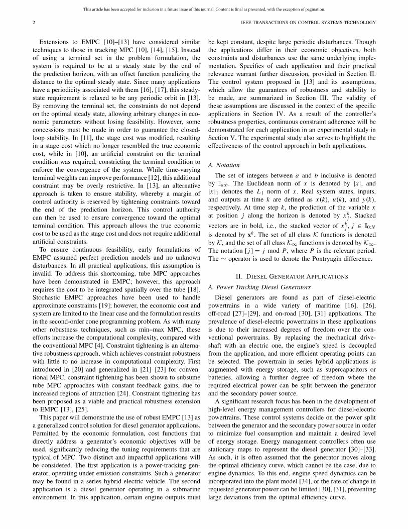
Fig. 1. Diesel engine at ACART dynamometer facility. 1: automotive dieselengine. 2: Horiba–Schenck transient dynamometer. 3: dSPACE MicroAuto-Box. 4: exhaust back pressure valve. 5: pressure and temperature sensors.
of the controller, the system will converge to be within a tubeabout the optimal solution. Convergence to a tube of solutions,rather than the exact optimal solution is a consequence ofunknown disturbances acting upon the system.
B. Test Bed Setup
To demonstrate the ability of the proposed controller inboth power tracking and submarine diesel generator appli-cations, a test bed was commissioned at The University ofMelbourne’s Advanced Centre for Automotive Research andTesting (ACART), as shown in Fig. 1. The test bed consists ofa four-cylinder, 3-L automotive diesel engine, equipped witha VGT and EGR. The engine’s native sensor set has beensupplemented with pressure and temperature sensors through-out the gas path, a turbine speed sensor, and oxygen sensorsin the intake and exhaust manifolds, permitting direct statefeedback. The generator is represented by a Horiba–Schenckdynamometer, which accepts a reference torque command.
To simulate the exhaust back pressure experienced by dieselengines on a submarine, a butterfly valve has been installedin the exhaust, as shown in Fig. 1. By controlling the backpressure valve, wave conditions corresponding up to sea state 6can be created [16], representing 99% of all sea conditions.
The engine’s native control unit has been replaced by adSPACE MicroAutoBox (MAB-Engine Control Unit (ECU)).The MAB-ECU is tasked with directly controlling all enginesubsystems, including fuel-rail pressure, exhaust back pressuretracking, and injection timing. The MAB-ECU also logs dataat the rates of up to 1 kHz.
To ensure that the time-critical tasks of the MAB-ECUwere not interrupted by the relatively processor-intensivecontroller, a second dSPACE MicroAutoBox (MAB-MPC)was used to implement the control system. The MAB-MPCcontains a 900-MHz IBM PPC processor. At each time step,the MAB-ECU sends the MAB-MPC the current systemstate over a CAN bus, which in turn responds with engineand dynamometer input commands. The MAB-MPC alsogenerates the back pressure reference signal for the submarineapplication.
C. Controller Implementation
The optimization problem (9) was solved using a sequentialquadratic programming (SQP) algorithm, described in thefollowing.
Consider a candidate control vector u. For a given initialstate and known disturbance sequence d the model dynam-ics (9c) can be used to generate a state trajectory x. A second-order Taylor series expansion of the nonlinear stage cost (6)about the trajectory (x, u) can be approximated by
V [k]s (�x,�u) = V [k]
s (x, u, p) + �uT Ju + �xT Jx
+ 1
2(�uT Hu�u + �xT Hx�x
+ �xT Hxu�u + �uT Hux�x) (10)
where[
Jx
Ju
]= ∂V [k]
s
∂[x u]
∣∣∣∣∣x,u
,
[Hx Hxu
Hux Hu
]= ∂2V [k]
s
∂[x u]2
∣∣∣∣∣x,u
.
Currently, (10) is a function of �u and �x, representinga sparse quadratic cost. The sparsity of the Hessian andJacobian of (10) permits compact representation in the code.However, the active-set QP solver used in this paper does nottake advantage of sparse problems. So to reduce the numberof decision variables, this cost is made dense through thetransformation �x = �u, where
=
⎡
⎢⎢⎢⎢⎢⎣
0 0 . . . 0B 0 . . . 0
AB B . . . 0...
.... . .
A(N−2) B A(N−3) B . . . B
⎤
⎥⎥⎥⎥⎥⎦∈ R
(N+1)n×Nm
allowing (10) to be recast as
V [k]s (�u) = V [k]
s (x, u, p) + J T �u + 1
2�uT H�u (11)
where
J := Ju + Jx, H := Hu + T Hx + T Hxu + Hux.
(12)
Since the initial term, V [k]s (x, u, p), is not a function of
the decision variables �u, it can be neglected. The terminalcost (7) represents a 1-norm, which can be directly incorpo-rated into the QP using additional slack decision variables,α ∈ R
Pn and associated constraints [52]. Following thesetransformations, define the QP optimization as:
arg min�u,α
J T �u + 1
2�uT H�u + α
s.t. �x = �u, x = x + �x, u = u + �u
(9b)–(9e)
xkN−P+ j − x[k+N+ j ] ≤ αi ∀i ∈ I0:P−1
xkN−P+ j − x[k+N+ j ] ≤ −αi ∀i ∈ I0:P−1. (13)
At any time step k and state x(k), the approximate solutionto (9) is found using Algorithm 1.
The SQP algorithm was implemented within a C MEXS-function using the MATLAB’s real-time workshop and
This article has been accepted for inclusion in a future issue of this journal. Content is final as presented, with the exception of pagination.
6 IEEE TRANSACTIONS ON CONTROL SYSTEMS TECHNOLOGY
Algorithm 1 Sequential Quadratic Programming
cross-compiled for the MAB-MPC. Where possible, equalityconstraints in (13) were resolved before calling the dual active-set QP solver described in [53]. Owing to the solution hot-starting of Algorithm 1, it was found in a simulation study thatimax could be reduced to as little as 1, without a notable impacton closed-loop performance. Since the recursive feasibilityguarantees do not require optimality of the control solution,there is no impact on recursive feasibility and hence constraintadherence. The computational load of the control systemis significantly reduced as a result, and the impact on thegenerated control inputs is quantified in Section V.A.
IV. APPLICATION SPECIFIC CONTROLLER FORMULATIONS
In the following, specific control formulations for the twoapplications are detailed. The validity of the assumptions madein Section III-A is discussed throughout.
A. System Model
The system model (1) was obtained from a high-ordernonlinear mean value engine model (MVEM). The modelwas calibrated on the test bed shown in Fig. 1 before thesystematic model reduction techniques discussed in [54] wereused to reduce the model order and linearize the dynamics.The system states, inputs, and disturbances are all normalized,ensuring that the optimization problem (13) is numericallywell conditioned.
For the power tracking application, the model has sevenstates xpt = [ωe, ωt, pim, Tim, Oim, xvgt, xegr], representingengine and turbine speed; pressure, temperature, and oxygenmass fraction of the gas in the intake manifold; and actuatorpositions for the VGT and the EGR. The system inputs areupt = [δ f , τgen, uvgt, uegr], which represent the fuel injectionduration, load torque on the engine from the dynamometer, andVGT and EGR actuator position commands. The period of thesystem is P = 1, trivially satisfying Assumption 1. The timestep was chosen as 100 ms, and the system disturbance, d ,was treated as a constant.
For the submarine application, EGR is not availableand thus facilitating further model reduction. The linearmodel has states xsub = [ωe, ωt, pim, xvgt] and inputsusub = [δ f , τgen, uvgt]. The control algorithm requiresprediction of at least one full period. In the submarineapplication, to highlight the benefits of the control system,
an aggressive sea state 6 was chosen to represent the backpressure, which has a period of 10 s. To limit the numberof decision variables required, a period of P = 10 waschosen with a time step of 1 s, satisfying Assumption 1. Theknown system disturbance d(k) included the exhaust backpressure pexh = 140 + 25.15 sin(2πk/10) kPa. To improveperformance, communication delays in the load torque andVGT commands were also modeled. These delays were lessthan one time step and were approximated with a Thiranfilter [55], requiring one additional state each.
B. Cost Function
The objective for a power tracking generator is to producethe requested power, while minimizing the fuel consumed todo so. This objective function can be directly addressed usingthe economic cost
lpt(x, u, p) = (Pgen(x, u) − p)2 + δ1m f (x, u)2 (14)
where Pgen and m f are the nonlinear functions representingthe generated power and fuel flow rate, obtained directly fromthe MVEM [54]. The economic parameter, p, represents therequested power. The relative weighting δ1 was chosen to besmall, to emphasize power tracking as the primary objective,though fine tuning of this weighting was not required. Thecost function (14) satisfies Assumption 4 however does notcurrently satisfy Assumption 3. It is known that strong dualitycan always be satisfied by adding an appropriate regularizationterm [9]. It was verified numerically that Assumption 3 wassatisfied by adding a relatively small term penalizing deviationof the engine speed from its optimal value
lpt(x, u, p) = (Pgen(x, u) − p)2 + δ1m f (x, u)2
+ δ2(ωe − ωref (p))2.
The terminal weighting term, γ , was chosen as γ0 from [13],sufficiently large to satisfy Assumption 8. A simulationstudy found that the controller performance improved withhorizon length, supporting the findings of [8]. For longhorizons, however, the optimization (13) cannot be solvedwithin one time step. A horizon length of N = 12 wasfound to be a suitable compromise, which is significantlylonger than the majority of MPC implementations for dieselengines [36]–[38].
Maintaining a constant engine speed and maintaining aconstant exhaust temperature are considered to be the primaryand secondary objectives for the submarine diesel generator,respectively. Given that these two objectives are achievable,a tertiary objective is to maximize the power produced bythe generator. These objectives can be addressed with theeconomic cost
lsub(x, u, d, p) = (ωe − ωref)2 + δ1(Tcyl(x, u, d) − Tref)
2
+ δ2(τgen − τmax)2 (15)
where ωref = 2050 rev/min is the reference engine speed,Tref = 750 K is the reference exhaust temperature, and τmax =300 N m is the maximum allowable torque for this engine.The weighting δ1 was chosen as 0.1 to emphasize enginespeed tracking as the primary objective, while the weighting δ2
This article has been accepted for inclusion in a future issue of this journal. Content is final as presented, with the exception of pagination.
BROOMHEAD et al.: EMPC AND APPLICATIONS FOR DIESEL GENERATORS 7
TABLE II
POWER TRACKING APPLICATION CONSTRAINTS
was made very small (10−6) to emphasize that the tertiaryobjective was only to be satisfied following the satisfactionof the primary and secondary objectives. Since 300 N m oftorque is unachievable given the target exhaust temperature,the third cost term only aims to maximize the torque, andhence power, produced by the generator. A linear approxi-mation, Tcyl(x, u, d), of the exhaust temperature Tcyl(x, u, d)ensures that both Assumptions 3 and 4 are satisfied. Thestage cost (6) is a function of only states (x), inputs (u),and the economic parameter (p). As such, the known periodicdisturbance term, d , must be explicitly incorporated into thecost function lsub(x, u, d, p), making it a periodically time-varying function, l[k]
sub(x, u, p). This periodic cost functionnow conforms to the structure of (6). The terminal weightingterm γ was also chosen as γ0 from [13], sufficiently largeto satisfy Assumption 8. A horizon length of N = 15 wascomputationally achievable, given the sample time.
C. Constraints
In the power tracking application, all inputs were upperand lower bounded, and the VGT and EGR inputs had slewrate constraints that represent the physical actuator limitations.Engine and turbine speed constraints were also enforced forsafe engine operation. These constraints are shown in Table II.The slew rate constraints can be enforced using the systemrepresentation (1) and (2) by augmenting the system matrices,output matrices, and state vector.
The manner in which the emissions are regulated differs bythe application. For example, for light duty road vehicles, thecumulative mass emissions of the regulated pollutants froma certification vehicle operating over a prescribed drive cycleare measured on a vehicle dynamometer, and must be belowsome regulated figure expressed in grams per kilometers. Forheavy duty road vehicles, in contrast, vehicle emissions areoften measured on vehicle dynamometers to monitor in-servicecompliance, but engine emissions are usually regulated forcertification purposes. In this latter case, the mass emissionsper unit shaft work at different engine operating points areaveraged to give an overall figure that must be below aregulated limit expressed in grams per kilowatt hours [56].
A distance-based metric is not well defined in many powertracking diesel generator applications; therefore, this paperconstrains the engine-out emissions on an instantaneous, gramsper kilowatt hours basis only. This is useful for several reasons.First, constraining engine-out emissions reduces the dynamicforcing of an after-treatment system, thereby reducing itslikely cost. Furthermore, applications, such as some stand-
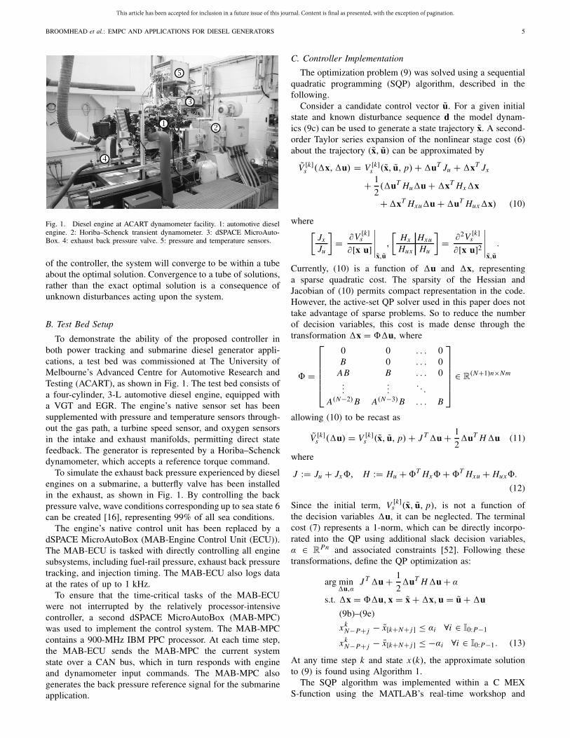
Fig. 2. Convex approximation (gray) of upper bound on Oim (black mesh)representing the bound mNO ≤ 6.
TABLE III
SUBMARINE APPLICATION CONSTRAINTS
alone diesel generators, off-road vehicles, and submarines,do not have after-treatment systems, and so engine-out andtailpipe emissions are essentially the same thing. Conse-quently, the NO and PM emissions constraints are instan-taneous constraints. Future work may consider the impactof relaxing this instantaneous constraint to be an averageconstraint over a finite time period using the frameworkprovided in [57]. The PM constraint is not set directly butrather by constraining λ as a surrogate, given an observedmonotonic relation between λ and an upper bound of PMemissions on this particular engine.
These two emission constraints are nonlinear and potentiallynonconvex. Since the constraints (2) must be linear and convexto satisfy Assumption 2, an approximation must be made.From the model, it is known from that mNO monotonicallyincreases with Oim. Therefore, a surface was created atmNO = 6 and solved for Oim, as shown in Fig. 2. This upperbound on Oim exactly represents the upper bound mNO ≤ 6.As shown in Fig. 2, half-spaces were used to conservativelyapproximate the surface, which can be described in theform (2). Assuming that the nonlinear constraint is convex, atradeoff between conservatism and computational complexitycan be made, by varying the number of half-spaces usedto represent the constraint. In the constraints used in thispaper, two half-spaces were used. The same approach wasused to conservatively approximate the λ bound, satisfyingAssumption 2.
In the submarine application, similar input constraintsare used, and a tighter bound on engine speed is applied,as shown in Table III. The submarine application doesnot include emissions constraints, however has bounds onthe allowable exhaust temperature, for system safety andreliability in the field. The exhaust temperature is againa nonlinear and potentially nonconvex function, which isapproximated with the same technique used for the emissionsconstraints, satisfying Assumption 2.
This article has been accepted for inclusion in a future issue of this journal. Content is final as presented, with the exception of pagination.
8 IEEE TRANSACTIONS ON CONTROL SYSTEMS TECHNOLOGY
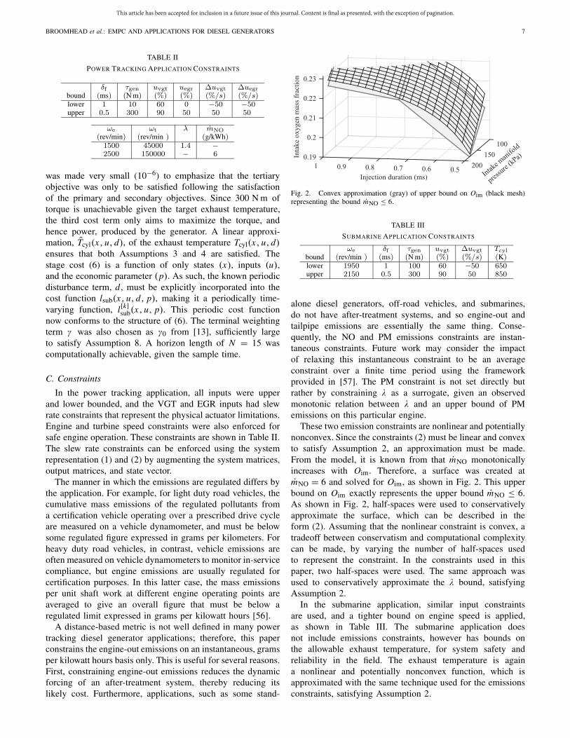
Fig. 3. Typical error distributions between reduced model and engine with5th and 95th percentiles (dashed line).
D. Model Error and Unknown Disturbances
The disturbance set W represents model error, measure-ment error, and unknown disturbances. The following methodwas used to approximate a separate disturbance set foreach application. First, a conservative estimate for W wasmade using the simulation data obtained in [54]. The EMPCcontroller was operated in closed loop on the engine, andengine states and inputs were recorded on the MAB-ECU.An error distribution between the engine measurements andthe linearized dynamics was then found, as shown in Fig. 3.In order for absolute guarantees to be made regarding con-straint adherence, the disturbance set W must contain theentire distribution of model error. In practice, however, theerrors w(k) are effectively unbounded. If the disturbance setW was made sufficiently large as to contain all possibledisturbances, then an overly restrictive constraint tighteningpolicy may result and Assumption 7 could be violated. Instead,a concession must be made, whereby the disturbance setcontains all model error within some probability. As such,the disturbance set W was chosen as the hypercube whichcontained between the 5th and 95th percentiles of measurederror terms, also highlighted in Fig. 3. As a result, absoluteguarantees for robustness are lost. However, the use of ahypercube to represent the set W is conservative and whencombined with other sources of conservatism within theapproach, the experiments demonstrate that practical robust-ness still remains. The hypercube used to represent W satisfiesAssumption 2.
Assumption 6 requires that any disturbances within the setW be regulated out using a set of controller gains K in a finitenumber of steps, Nnil. These control gains were designed usinga finite horizon Linear-Quadratic Regulator approach, similarto that in [23] and [25]. Assumption 5 is satisfied throughthe construction of Xt and Ut , which for both applicationsfollowed the recommended procedure in [13]. The tightenedconstraints were then calculated offline using the invariant settoolbox [58] according to the policy (5).
E. Terminal ConditionsThe optimal terminal trajectories, x∗, are required in order
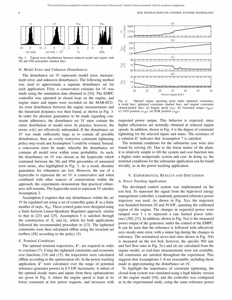
to construct (7). Using the tightened constraints and economiccost functions (14) and (15), the trajectories were calculatedoffline according to the optimization (8). In the power trackingapplication, x∗ were calculated over the range of potentialreference generator powers in 0.5 kW increments. A subset ofthe optimal steady states and inputs from these optimizationsare given in Fig. 4, where the engine speed is kept at itslower constraint at low power requests, and increases with
Fig. 4. Optimal engine operating point under tightened constraints,x (solid line), tightened constraints (dashed line), and original constraints(dotted-dashed line). (a) Engine speed (ωe). (b) Generator torque (τgen).(c) VGT position (xvgt). (d) EGR position (xegr ).
requested power output. This behavior is expected, sincehigher efficiencies are normally obtained at reduced enginespeeds. In addition, shown in Fig. 4 is the degree of constrainttightening for the selected inputs and states. The existence ofa solution x∗ indicates that Assumption 7 is satisfied.
The terminal conditions for the submarine case were alsofound by solving (8). Due to the linear nature of the plant,it is relatively simple to lift the system and cost function intoa higher order nonperiodic system and cost. In doing so, theterminal conditions for the submarine application can be foundtrivially, as in the power tracking application.
V. EXPERIMENTAL RESULTS AND DISCUSSION
A. Power Tracking Application
The developed control system was implemented on thetest bed. To represent the signal from the high-level energymanagement controller, a randomly generated reference powertrajectory was used. As shown in Fig. 5(a), the trajectorywas bounded between 20 and 50 kW, spanning the calibratedregion of the engine. The changes in requested power wereramped over 1 s to represent a rate limited power refer-ence [30], [31]. In addition, shown in Fig. 5(a) is the measuredpower output of the generator, under the control of the EMPC.It can be seen that the reference is followed with effectivelyzero steady-state error, with a minor lag during the changes inreference. The normalized air-to-fuel ratio shown in Fig. 5(b)is measured on the test bed; however, the specific NO rateand fuel flow rates in Fig. 5(c) and (d) are calculated from theengine model, as real-time measurements were not available.All constraints are satisfied throughout the experiment. Thissuggests that Assumptions 1–8 are reasonable, including thosemade in approximating the disturbance set W .
To highlight the importance of constraint tightening, theclosed-loop system was simulated using a high fidelity versionof the engine model [54], and the controller was configuredas in the experimental study, using the same reference power
This article has been accepted for inclusion in a future issue of this journal. Content is final as presented, with the exception of pagination.
BROOMHEAD et al.: EMPC AND APPLICATIONS FOR DIESEL GENERATORS 9
Fig. 5. Engine outputs (solid line), power reference (dotted-dashed line), andoriginal constraints (dashed line). Fuel mass-flow rate and specific NO rateare calculated from model. Right hand plots show further detail for t = (4, 8).(a) Generator power (Pgen). (b) Normalized air-to-fuel ratio (λ). (c) SpecificNO rate (mNO). (d) Fuel mass-flow rate (m f ). (e) Engine speed (ωe).(f) Fuel injection duration (δ f ). (g) Generator torque command (τgen).(h) VGT position command (uvgt). (i) EGR position command (uegr).
trajectory, initial condition. The disturbance set was set toW = 0, eliminating the effects of constraint tightening.With this configuration, the optimization failed on the fifth
Fig. 6. Distribution of computation time for the EMPC during experiments.
Fig. 7. Measured BSFC from closed-loop test (crosses) and from steady-statesweeps (points).
time step, with a violation of the engine speed lower boundingconstraint.
By calculating the tightened constraints (5) offline andkeeping the cost function approximation (10) in an explicit andsparse form, very little time is taken to construct the QP (13)at each time step. Furthermore, since Algorithm 1 hot-startsthe solution, imax = 1 could be used with minimal impact onperformance. As a result, the relatively long horizon length ofN = 12 was consistently computed well within one time step,as shown in Fig. 6.
The error introduced by using imax = 1 was quantifiedthrough a simulation study. The closed-loop system was sim-ulated using a high fidelity version of the engine model [54],and the controller was configured as in the experimental study,using the same reference power trajectory. In addition, asecond EMPC implementation was run in parallel, receivingthe same input data; however, its SQP iteration limit wasremoved and δtol was set to 10−6. In this way, the errorintroduced by the iteration limit of 1 could be quantified. TheSQP algorithm without an iteration limit converged quickly,with all cases converging within four iterations, and 95% ofcases within two iterations. It was found that in 98.25% ofcases, the normalized control inputs were within 0.1% of eachother, while in 99.47% of cases, they were within 1% ofeach other. Considering the magnitude of disturbances on thesystem, these values are considered small.
At the points marked by crosses in Fig. 5(a), the enginewas at steady state for long enough to measure its brakespecific fuel consumption (BSFC). The BSFC at these pointsis shown in Fig. 7, alongside the BSFC measured duringthe model calibration procedure, which consisted of sweepsin engine inputs. Despite the conservatism introduced in theconstraints, the closed-loop system was operated near itsminimum fuel consumption over the wide range of referencepowers tested. Since the requested power was met and theengine was operated close to its minimum BSFC, it is clearthat the objectives of the diesel generator are satisfied usingthe economic cost (14).
This article has been accepted for inclusion in a future issue of this journal. Content is final as presented, with the exception of pagination.
10 IEEE TRANSACTIONS ON CONTROL SYSTEMS TECHNOLOGY
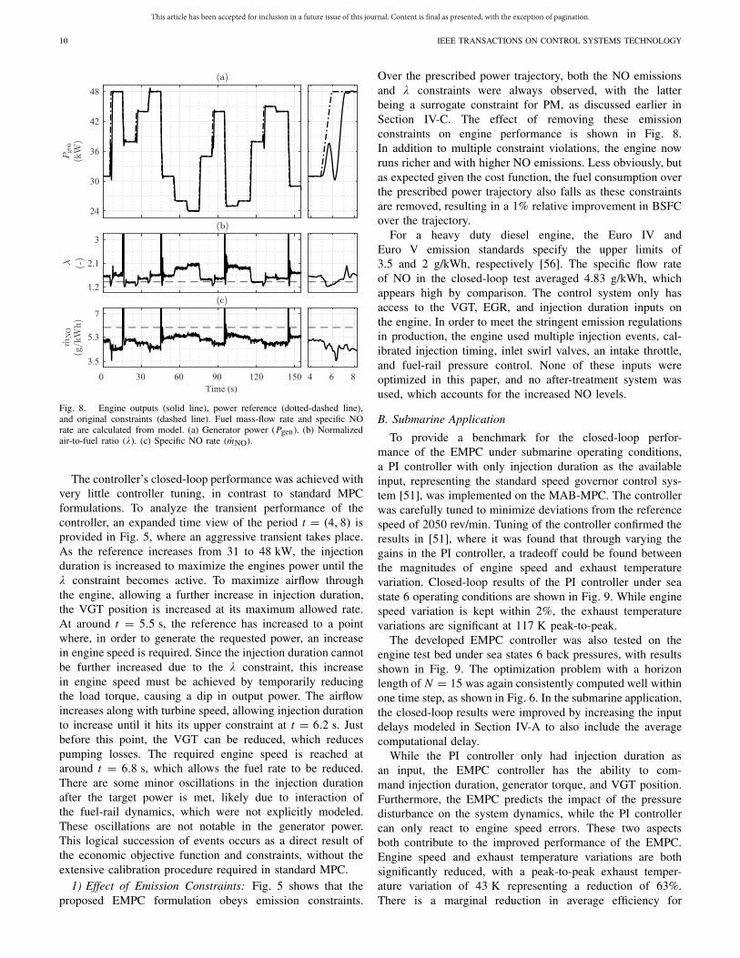
Fig. 8. Engine outputs (solid line), power reference (dotted-dashed line),and original constraints (dashed line). Fuel mass-flow rate and specific NOrate are calculated from model. (a) Generator power (Pgen). (b) Normalizedair-to-fuel ratio (λ). (c) Specific NO rate (mNO).
The controller’s closed-loop performance was achieved withvery little controller tuning, in contrast to standard MPCformulations. To analyze the transient performance of thecontroller, an expanded time view of the period t = (4, 8) isprovided in Fig. 5, where an aggressive transient takes place.As the reference increases from 31 to 48 kW, the injectionduration is increased to maximize the engines power until theλ constraint becomes active. To maximize airflow throughthe engine, allowing a further increase in injection duration,the VGT position is increased at its maximum allowed rate.At around t = 5.5 s, the reference has increased to a pointwhere, in order to generate the requested power, an increasein engine speed is required. Since the injection duration cannotbe further increased due to the λ constraint, this increasein engine speed must be achieved by temporarily reducingthe load torque, causing a dip in output power. The airflowincreases along with turbine speed, allowing injection durationto increase until it hits its upper constraint at t = 6.2 s. Justbefore this point, the VGT can be reduced, which reducespumping losses. The required engine speed is reached ataround t = 6.8 s, which allows the fuel rate to be reduced.There are some minor oscillations in the injection durationafter the target power is met, likely due to interaction ofthe fuel-rail dynamics, which were not explicitly modeled.These oscillations are not notable in the generator power.This logical succession of events occurs as a direct result ofthe economic objective function and constraints, without theextensive calibration procedure required in standard MPC.
1) Effect of Emission Constraints: Fig. 5 shows that theproposed EMPC formulation obeys emission constraints.
Over the prescribed power trajectory, both the NO emissionsand λ constraints were always observed, with the latterbeing a surrogate constraint for PM, as discussed earlier inSection IV-C. The effect of removing these emissionconstraints on engine performance is shown in Fig. 8.In addition to multiple constraint violations, the engine nowruns richer and with higher NO emissions. Less obviously, butas expected given the cost function, the fuel consumption overthe prescribed power trajectory also falls as these constraintsare removed, resulting in a 1% relative improvement in BSFCover the trajectory.
For a heavy duty diesel engine, the Euro IV andEuro V emission standards specify the upper limits of3.5 and 2 g/kWh, respectively [56]. The specific flow rateof NO in the closed-loop test averaged 4.83 g/kWh, whichappears high by comparison. The control system only hasaccess to the VGT, EGR, and injection duration inputs onthe engine. In order to meet the stringent emission regulationsin production, the engine used multiple injection events, cal-ibrated injection timing, inlet swirl valves, an intake throttle,and fuel-rail pressure control. None of these inputs wereoptimized in this paper, and no after-treatment system wasused, which accounts for the increased NO levels.
B. Submarine Application
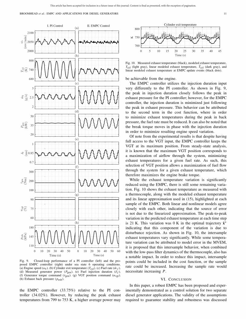
To provide a benchmark for the closed-loop perfor-mance of the EMPC under submarine operating conditions,a PI controller with only injection duration as the availableinput, representing the standard speed governor control sys-tem [51], was implemented on the MAB-MPC. The controllerwas carefully tuned to minimize deviations from the referencespeed of 2050 rev/min. Tuning of the controller confirmed theresults in [51], where it was found that through varying thegains in the PI controller, a tradeoff could be found betweenthe magnitudes of engine speed and exhaust temperaturevariation. Closed-loop results of the PI controller under seastate 6 operating conditions are shown in Fig. 9. While enginespeed variation is kept within 2%, the exhaust temperaturevariations are significant at 117 K peak-to-peak.
The developed EMPC controller was also tested on theengine test bed under sea states 6 back pressures, with resultsshown in Fig. 9. The optimization problem with a horizonlength of N = 15 was again consistently computed well withinone time step, as shown in Fig. 6. In the submarine application,the closed-loop results were improved by increasing the inputdelays modeled in Section IV-A to also include the averagecomputational delay.
While the PI controller only had injection duration asan input, the EMPC controller has the ability to com-mand injection duration, generator torque, and VGT position.Furthermore, the EMPC predicts the impact of the pressuredisturbance on the system dynamics, while the PI controllercan only react to engine speed errors. These two aspectsboth contribute to the improved performance of the EMPC.Engine speed and exhaust temperature variations are bothsignificantly reduced, with a peak-to-peak exhaust temper-ature variation of 43 K representing a reduction of 63%.There is a marginal reduction in average efficiency for
This article has been accepted for inclusion in a future issue of this journal. Content is final as presented, with the exception of pagination.
BROOMHEAD et al.: EMPC AND APPLICATIONS FOR DIESEL GENERATORS 11
Fig. 9. Closed-loop performance of a PI controller (left) and the pro-posed EMPC controller (right) under sea state 6 operating conditions.(a) Engine speed (ωe). (b) Cylinder exit temperature (Tcyl). (c) Fuel rate (m f ).(d) Measured generator power (Pgen). (e) Fuel injection duration (δ f ).(f) Generator torque command (τgen). (g) VGT position command (uvgt).(h) Exhaust back pressure (pexh).
the EMPC controller (33.75%) relative to the PI con-troller (34.02%). However, by reducing the peak exhausttemperatures from 799 to 753 K, a higher average power may
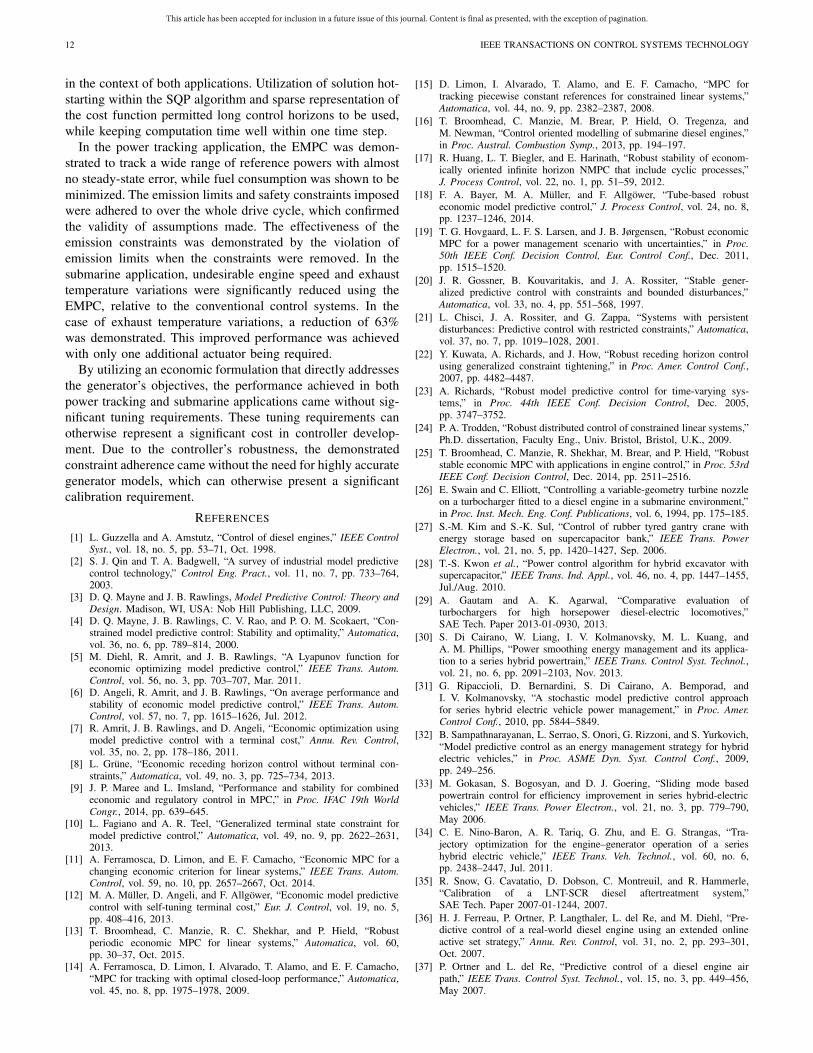
Fig. 10. Measured exhaust temperature (black), modeled exhaust temperature,Tcyl (light gray), linear modeled exhaust temperature, Tcyl (dark gray), andlinear modeled exhaust temperature at EMPC update events (black dots).
be achievable from the engine.The EMPC controller utilizes the injection duration input
very differently to the PI controller. As shown in Fig. 9,the peak in injection duration closely follows the peak inexhaust pressure for the PI controller; however, for the EMPCcontroller, the injection duration is minimized just followingthe peak in exhaust pressure. This behavior can be attributedto the second term in the cost function, where in orderto minimize exhaust temperatures during the peak in backpressure, the fuel rate must be reduced. It can also be noted thatthe break torque moves in phase with the injection durationin order to minimize resulting engine speed variation.
Of note from the experimental results is that despite havingfull access to the VGT input, the EMPC controller keeps theVGT at its maximum position. From steady-state analysis,it is known that the maximum VGT position corresponds toa maximization of airflow through the system, minimizingexhaust temperatures for a given fuel rate. As such, thisselection of VGT position allows a maximization of fuel flowthrough the system for a given exhaust temperature, whichtherefore maximizes the engine brake torque.
While the exhaust temperature variation is significantlyreduced using the EMPC, there is still some remaining varia-tion. Fig. 10 shows the exhaust temperature as measured witha thermocouple, along with the modeled exhaust temperatureand its linear approximation used in (15), highlighted at eachsample of the EMPC. Both linear and nonlinear models agreeclosely with each other, indicating that the source of erroris not due to the linearized approximation. The peak-to-peakvariation in the predicted exhaust temperature at each time stepis 21 K. This variation was 0 K in the optimal trajectory x∗indicating that this component of the variation is due todisturbance rejection. As shown in Fig. 10, the intersampleexhaust temperatures vary significantly. While some tempera-ture variation can be attributed to model error in the MVEM,it is proposed that this intersample behavior, when combinedwith the low-pass filter dynamics of the thermocouple, also hasa notable impact. In order to reduce this impact, intersamplepoints could be included in the cost function, or the samplerate could be increased. Increasing the sample rate wouldnecessitate increasing P .
VI. CONCLUSION
In this paper, a robust EMPC has been proposed and exper-imentally demonstrated as a control solution for two separatediesel generator applications. The validity of the assumptionsrequired to guarantee stability and robustness was discussed
This article has been accepted for inclusion in a future issue of this journal. Content is final as presented, with the exception of pagination.
12 IEEE TRANSACTIONS ON CONTROL SYSTEMS TECHNOLOGY
in the context of both applications. Utilization of solution hot-starting within the SQP algorithm and sparse representation ofthe cost function permitted long control horizons to be used,while keeping computation time well within one time step.
In the power tracking application, the EMPC was demon-strated to track a wide range of reference powers with almostno steady-state error, while fuel consumption was shown to beminimized. The emission limits and safety constraints imposedwere adhered to over the whole drive cycle, which confirmedthe validity of assumptions made. The effectiveness of theemission constraints was demonstrated by the violation ofemission limits when the constraints were removed. In thesubmarine application, undesirable engine speed and exhausttemperature variations were significantly reduced using theEMPC, relative to the conventional control systems. In thecase of exhaust temperature variations, a reduction of 63%was demonstrated. This improved performance was achievedwith only one additional actuator being required.
By utilizing an economic formulation that directly addressesthe generator’s objectives, the performance achieved in bothpower tracking and submarine applications came without sig-nificant tuning requirements. These tuning requirements canotherwise represent a significant cost in controller develop-ment. Due to the controller’s robustness, the demonstratedconstraint adherence came without the need for highly accurategenerator models, which can otherwise present a significantcalibration requirement.
REFERENCES
[1] L. Guzzella and A. Amstutz, “Control of diesel engines,” IEEE ControlSyst., vol. 18, no. 5, pp. 53–71, Oct. 1998.
[2] S. J. Qin and T. A. Badgwell, “A survey of industrial model predictivecontrol technology,” Control Eng. Pract., vol. 11, no. 7, pp. 733–764,2003.
[3] D. Q. Mayne and J. B. Rawlings, Model Predictive Control: Theory andDesign. Madison, WI, USA: Nob Hill Publishing, LLC, 2009.
[4] D. Q. Mayne, J. B. Rawlings, C. V. Rao, and P. O. M. Scokaert, “Con-strained model predictive control: Stability and optimality,” Automatica,vol. 36, no. 6, pp. 789–814, 2000.
[5] M. Diehl, R. Amrit, and J. B. Rawlings, “A Lyapunov function foreconomic optimizing model predictive control,” IEEE Trans. Autom.Control, vol. 56, no. 3, pp. 703–707, Mar. 2011.
[6] D. Angeli, R. Amrit, and J. B. Rawlings, “On average performance andstability of economic model predictive control,” IEEE Trans. Autom.Control, vol. 57, no. 7, pp. 1615–1626, Jul. 2012.
[7] R. Amrit, J. B. Rawlings, and D. Angeli, “Economic optimization usingmodel predictive control with a terminal cost,” Annu. Rev. Control,vol. 35, no. 2, pp. 178–186, 2011.
[8] L. Grüne, “Economic receding horizon control without terminal con-straints,” Automatica, vol. 49, no. 3, pp. 725–734, 2013.
[9] J. P. Maree and L. Imsland, “Performance and stability for combinedeconomic and regulatory control in MPC,” in Proc. IFAC 19th WorldCongr., 2014, pp. 639–645.
[10] L. Fagiano and A. R. Teel, “Generalized terminal state constraint formodel predictive control,” Automatica, vol. 49, no. 9, pp. 2622–2631,2013.
[11] A. Ferramosca, D. Limon, and E. F. Camacho, “Economic MPC for achanging economic criterion for linear systems,” IEEE Trans. Autom.Control, vol. 59, no. 10, pp. 2657–2667, Oct. 2014.
[12] M. A. Müller, D. Angeli, and F. Allgöwer, “Economic model predictivecontrol with self-tuning terminal cost,” Eur. J. Control, vol. 19, no. 5,pp. 408–416, 2013.
[13] T. Broomhead, C. Manzie, R. C. Shekhar, and P. Hield, “Robustperiodic economic MPC for linear systems,” Automatica, vol. 60,pp. 30–37, Oct. 2015.
[14] A. Ferramosca, D. Limon, I. Alvarado, T. Alamo, and E. F. Camacho,“MPC for tracking with optimal closed-loop performance,” Automatica,vol. 45, no. 8, pp. 1975–1978, 2009.
[15] D. Limon, I. Alvarado, T. Alamo, and E. F. Camacho, “MPC fortracking piecewise constant references for constrained linear systems,”Automatica, vol. 44, no. 9, pp. 2382–2387, 2008.
[16] T. Broomhead, C. Manzie, M. Brear, P. Hield, O. Tregenza, andM. Newman, “Control oriented modelling of submarine diesel engines,”in Proc. Austral. Combustion Symp., 2013, pp. 194–197.
[17] R. Huang, L. T. Biegler, and E. Harinath, “Robust stability of econom-ically oriented infinite horizon NMPC that include cyclic processes,”J. Process Control, vol. 22, no. 1, pp. 51–59, 2012.
[18] F. A. Bayer, M. A. Müller, and F. Allgöwer, “Tube-based robusteconomic model predictive control,” J. Process Control, vol. 24, no. 8,pp. 1237–1246, 2014.
[19] T. G. Hovgaard, L. F. S. Larsen, and J. B. Jørgensen, “Robust economicMPC for a power management scenario with uncertainties,” in Proc.50th IEEE Conf. Decision Control, Eur. Control Conf., Dec. 2011,pp. 1515–1520.
[20] J. R. Gossner, B. Kouvaritakis, and J. A. Rossiter, “Stable gener-alized predictive control with constraints and bounded disturbances,”Automatica, vol. 33, no. 4, pp. 551–568, 1997.
[21] L. Chisci, J. A. Rossiter, and G. Zappa, “Systems with persistentdisturbances: Predictive control with restricted constraints,” Automatica,vol. 37, no. 7, pp. 1019–1028, 2001.
[22] Y. Kuwata, A. Richards, and J. How, “Robust receding horizon controlusing generalized constraint tightening,” in Proc. Amer. Control Conf.,2007, pp. 4482–4487.
[23] A. Richards, “Robust model predictive control for time-varying sys-tems,” in Proc. 44th IEEE Conf. Decision Control, Dec. 2005,pp. 3747–3752.
[24] P. A. Trodden, “Robust distributed control of constrained linear systems,”Ph.D. dissertation, Faculty Eng., Univ. Bristol, Bristol, U.K., 2009.
[25] T. Broomhead, C. Manzie, R. Shekhar, M. Brear, and P. Hield, “Robuststable economic MPC with applications in engine control,” in Proc. 53rdIEEE Conf. Decision Control, Dec. 2014, pp. 2511–2516.
[26] E. Swain and C. Elliott, “Controlling a variable-geometry turbine nozzleon a turbocharger fitted to a diesel engine in a submarine environment,”in Proc. Inst. Mech. Eng. Conf. Publications, vol. 6, 1994, pp. 175–185.
[27] S.-M. Kim and S.-K. Sul, “Control of rubber tyred gantry crane withenergy storage based on supercapacitor bank,” IEEE Trans. PowerElectron., vol. 21, no. 5, pp. 1420–1427, Sep. 2006.
[28] T.-S. Kwon et al., “Power control algorithm for hybrid excavator withsupercapacitor,” IEEE Trans. Ind. Appl., vol. 46, no. 4, pp. 1447–1455,Jul./Aug. 2010.
[29] A. Gautam and A. K. Agarwal, “Comparative evaluation ofturbochargers for high horsepower diesel-electric locomotives,”SAE Tech. Paper 2013-01-0930, 2013.
[30] S. Di Cairano, W. Liang, I. V. Kolmanovsky, M. L. Kuang, andA. M. Phillips, “Power smoothing energy management and its applica-tion to a series hybrid powertrain,” IEEE Trans. Control Syst. Technol.,vol. 21, no. 6, pp. 2091–2103, Nov. 2013.
[31] G. Ripaccioli, D. Bernardini, S. Di Cairano, A. Bemporad, andI. V. Kolmanovsky, “A stochastic model predictive control approachfor series hybrid electric vehicle power management,” in Proc. Amer.Control Conf., 2010, pp. 5844–5849.
[32] B. Sampathnarayanan, L. Serrao, S. Onori, G. Rizzoni, and S. Yurkovich,“Model predictive control as an energy management strategy for hybridelectric vehicles,” in Proc. ASME Dyn. Syst. Control Conf., 2009,pp. 249–256.
[33] M. Gokasan, S. Bogosyan, and D. J. Goering, “Sliding mode basedpowertrain control for efficiency improvement in series hybrid-electricvehicles,” IEEE Trans. Power Electron., vol. 21, no. 3, pp. 779–790,May 2006.
[34] C. E. Nino-Baron, A. R. Tariq, G. Zhu, and E. G. Strangas, “Tra-jectory optimization for the engine–generator operation of a serieshybrid electric vehicle,” IEEE Trans. Veh. Technol., vol. 60, no. 6,pp. 2438–2447, Jul. 2011.
[35] R. Snow, G. Cavatatio, D. Dobson, C. Montreuil, and R. Hammerle,“Calibration of a LNT-SCR diesel aftertreatment system,”SAE Tech. Paper 2007-01-1244, 2007.
[36] H. J. Ferreau, P. Ortner, P. Langthaler, L. del Re, and M. Diehl, “Pre-dictive control of a real-world diesel engine using an extended onlineactive set strategy,” Annu. Rev. Control, vol. 31, no. 2, pp. 293–301,Oct. 2007.
[37] P. Ortner and L. del Re, “Predictive control of a diesel engine airpath,” IEEE Trans. Control Syst. Technol., vol. 15, no. 3, pp. 449–456,May 2007.
This article has been accepted for inclusion in a future issue of this journal. Content is final as presented, with the exception of pagination.
BROOMHEAD et al.: EMPC AND APPLICATIONS FOR DIESEL GENERATORS 13
[38] J. Wahlström and L. Eriksson, “Output selection and its implications forMPC of EGR and VGT in diesel engines,” IEEE Trans. Control Syst.Technol., vol. 21, no. 3, pp. 932–940, May 2013.
[39] S. Kim, H. Jin, and S. Choi, “Pressure and flow based control of aturbocharged diesel engine air-path system equipped with dual-loopEGR and VGT,” in Proc. Amer. Control Conf., 2014, pp. 1493–1498.
[40] A. G. Stefanopoulou, I. Kolmanovsky, and J. S. Freudenberg, “Control ofvariable geometry turbocharged diesel engines for reduced emissions,”IEEE Trans. Control Syst. Technol., vol. 8, no. 4, pp. 733–745, Jul. 2000.
[41] J. Halme and J. Suomela, “Optimal efficiency based gen-set control forseries hybrid work machine,” in Proc. IEEE Vehicle Power Propuls.Conf. (VPPC), Oct. 2012, pp. 836–839.
[42] M. Sivertsson and L. Eriksson, “Optimal transient control trajectoriesin diesel–electric systems—Part I: Modeling, problem formulation, andengine properties,” J. Eng. Gas Turbines Power, vol. 137, no. 2,p. 021601, 2014.
[43] B. He and M. Yang, “Robust LPV control of diesel auxiliary powerunit for series hybrid electric vehicles,” IEEE Trans. Power Electron.,vol. 21, no. 3, pp. 791–798, May 2006.
[44] J. Buckingham and J. Mann, “Multi-engine submarine power supplies:The operating case,” in Proc. Int. Maritime Conf., 2010, pp. 416–428.
[45] J. W. Mann, “Twin-turbocharged diesel performance under snorkellingconditions,” in Proc. Undersea Defence Technol., 2011, pp. 1–11.
[47] E. T. F. Kirkman and R. A. Hopper, “Turbocharging for submarines—A special case,” in Proc. Int. Conf. Turbochargers Turbocharging,IMechE, 1990, pp. 229–239.
[48] P. Hield, “The effect of back pressure on the operation of a dieselengine,” Defence Sci. Technol. group, Fishermans Bend, VIC, Australia,Tech. Rep. DSTO-TR-2531, 2011.
[49] V. M. W. Jost, “Exhaust gas turbocharged submarine engines,” in Proc.RINA Int. Symp. Naval Submarines, London, U.K., May 1983.
[50] E. van den Pol, “The simulation of the dynamic pressure variationsinside snorkeling submarines,” Schip en Werf, pp. 211–216, 1987.
[51] P. Hield and M. Newman, “Assessment of governor control parametersettings of a submarine diesel engine,” Defence Sci. Technol. group,Fishermans Bend, VIC, Australia, Tech. Rep. DSTO-RR-0386, 2013.
[52] C. V. Rao and J. B. Rawlings, “Linear programming and modelpredictive control,” J. Process Control, vol. 10, no. 2, pp. 283–289, 2000.
[53] A. G. Wills, G. Knagge, and B. Ninness, “Fast linear model predictivecontrol via custom integrated circuit architecture,” IEEE Trans. ControlSyst. Technol., vol. 20, no. 1, pp. 59–71, Jan. 2012.
[54] T. Broomhead, C. Manzie, M. Brear, and P. Hield, “Model reductionof diesel mean value engine models,” SAE Tech. Paper 2015-01-1248,2015.
[55] T. I. Laakso, V. Valimaki, M. Karjalainen, and U. K. Laine, “Splittingthe unit delay [FIR/all pass filters design],” IEEE Signal Process. Mag.,vol. 13, no. 1, pp. 30–60, Jan. 1996.
[56] Directive 2005/55/EC of the European Parliament and of the Council,Eur. Parliament Council Eur. Union, Official Journal of the EuropeanUnion, document no., 2005.
[57] M. A. Müller, D. Angeli, and F. Allgöwer, “Transient average constraintsin economic model predictive control,” Automatica, vol. 50, no. 11,pp. 2943–2950, 2014.
[58] E. C. Kerrigan, “Robust constraint satisfaction: Invariant sets andpredictive control,” Ph.D. dissertation, Dept. Eng., Univ. Cambridge,Cambridge, U.K., 2000.
Timothy Broomhead received the bachelor’sdegrees in mechatronic engineering and com-puter science from The University of Melbourne,Parkville, VIC, Australia, in 2011, where he hasbeen pursuing the Ph.D. degree since 2012. Histhesis investigates the development of robust modelbased control algorithms and their application todiesel engine generators.
He was a Visiting Student to Linköping University,Linköping, Sweden, and has been involved with theDefence Science and Technology Group, Melbourne,
VIC, Australia.Mr. Broomhead received the Elizabeth and Vernon Puzey Scholarship
in 2012. He was included in the Dean’s Honours List, The University ofMelbourne.
Chris Manzie was a Visiting Scholar with theUniversity of California at San Diego, La Jolla,CA, USA, in 2007, and a Visiteur Scientifique withIFP Energies Nouvelles, Rueil-Malmaison, France,in 2012. He is currently a Professor with the Depart-ment of Mechanical Engineering, The Universityof Melbourne, Parkville, VIC, Australia, and anAssistant Dean (Research Training) of the Schoolof Engineering with The University of Melbourne.He has been supported by strong industry collab-orations with a number of companies, including
Toyota Motor Corporation, BAE Systems, ANCA Motion, and DSTG. Hiscurrent research interests include model-based and model-free control andoptimization, with applications in a range of areas, including systems relatedto energy, transportation, and mechatronics.
Prof. Manzie received an Australian Research Council Future Fellowshipfrom 2011 to 2014. He is an Associate Editor of Control EngineeringPractice (Elsevier), the IEEE TRANSACTIONS ON MECHATRONICS/ASMETransactions on Mechatronics, and the IEEE TRANSACTIONS ON CONTROL
SYSTEMS TECHNOLOGY.
Peter Hield received the M.Eng. degree from Impe-rial College London, London, U.K., in 2002, andthe Ph.D. degree from The University of Melbourne,Parkville, VIC, Australia, titled an experimental andtheoretical investigation of thermoacoustic instabilityin a turbulent premixed laboratory combustor, in2008.
He has been involved in a variety of processindustry mechanical engineering positions, beforejoining the Defence Science and Technology Group,Melbourne, VIC, Australia, in 2010. He is currently
with the Power and Energy Systems Group, Maritime Division, specializingin submarine diesel engines.
Dr. Hield received the Dr. John Patterson Prize for the best thesis from theSchool of Engineering for this work.
Rohan Shekhar received the B.E. (Hons.) degreein mechatronic engineering from The University ofQueensland, Brisbane, QLD, Australia, in 2006, andthe Ph.D. degree from the University of Cambridge,Cambridge, U.K., in 2012.
He is currently a Post-Doctoral Research Fel-low with The University of Melbourne, Parkville,VIC, Australia. His current research interests includerobust model predictive control, with applicationsto automotive systems, autonomous vehicles, miningtechnology, and robotics.
Dr. Shekhar received the Sir Robert Menzies Memorial Scholarship inEngineering and an Honorary Poynton Cambridge Australia Fellowship forundertaking doctoral studies at the University of Cambridge in 2008.
Michael Brear was with Orica, and then undertookgraduate studies with the University of Cambridge,Cambridge, U.K., and post-doctoral researchwith the Massachusetts Institute of Technology,Cambridge, MA, USA. He is currently a Professorof Engineering with The University of Melbourne,Parkville, VIC, Australia, and a fellow of bothEngineers Australia and the Australian Instituteof Energy. He is involved in transport and powergeneration, examining the performance of lowemission technologies individually and when
integrated into systems. This involves close collaboration with FordMotor Company, Australian Energy Market Operator, Princeton University,Princeton, NJ, USA, and others. He also established and teaches into theUniversity’s Master of Energy Systems, which is a multidisciplinary degreethat integrates the technical, commercial, and policy aspects of energy.