IEEE TRANSACTIONS ON MICROWAVE THEORY AND TECHNIQUES, VOL. 52, NO. 5, MAY 2004 1523
On the Noise Properties ofInjection-Locked Oscillators
Evgeny Shumakher and Gadi Eisenstein, Fellow, IEEE
Abstract—This paper presents a detailed study of noise prop-erties of injection-locked oscillators. We describe an elaborate nu-merical model, which offers the accuracy of the best known ana-lytical models when analyzing a single oscillator. Those analyticalmodels do not use perturbation theory since the Wiener nature ofthe noise renders small-signal analysis inadequate. Our model canbe extended to any locked oscillators configuration while keepingthe same accuracy. This was not done to date with any of the rig-orous analytical models.
We analyze unidirectionally and bidirectionally coupled oscilla-tors operating in fundamental or harmonic-locking modes. Har-monic locking is analyzed in detail and the indirect locking processunderlying it is identified while the noise of all harmonics is ex-plored in detail.
The results of the model are confirmed in a series of experimentsemploying electrooptic implementations with a photo-HBT-basedoscillator. The various configurations we analyze and demonstrateexperimentally represent important applications such as spectralpurity enhancement, timing extraction, and low-jitter optical pulsegeneration.
Index Terms—Injection-locked amplifiers, injection-lockedoscillators, microwave oscillators, opto-electronic devices, phasenoise.
I. INTRODUCTION
THE operating characteristics of any autonomous oscil-lating system include a degree of uncertainty in its output
signal due to noise. The deviations from a predictable state area fundamental property and, as such, have been studied formany years. An accurate analysis of fluctuations in an isolatedautonomous system has been published as early as the 1930sby Bernstein [1] and numerous follow-up treatments withvarying degrees of rigor and accuracy have been presented eversince [2]–[5]. A recent important paper by Demir et al. [3] hasreemphasized the difficulty of treating this seemingly simpleproblem in an analytical rigorous manner. In particular, [3]proves that the phase variance of the oscillating signal increasesindefinitely (namely, in the presence of white Gaussian noise(WGN), the variance of the phase deviations grows linearlywith time) and, hence, classical small-signal noise analysis,used in numerous calculations [4], [5] is inadequate.
An additional step in complexity arises when forced oscilla-tions (widely known as injection locking [6]) are considered.In fundamental locking [7], the two interacting systems operate
Manuscript received November 30, 2003; revised February 4, 2004. Thiswork was supported in part by the Israeli Academy of Sciences.
The authors are with the Electrical Engineering Department,Technion—Israel Institute of Technology, Haifa 32000, Israel (e-mail: [email protected]).
Digital Object Identifier 10.1109/TMTT.2004.827035
at nominally the same frequency, while in the more intricateconcept of harmonic locking [8], the interaction is between sys-tems whose frequencies are harmonics of each other. The mostcomplicated coupled configurations involve fundamental or har-monic bidirectionally coupled systems. All known analyses ofthose nonlinear injection-locked systems rely on small-signalperturbation theory [9], [10] and, therefore, lack the accuracyof the exact single-oscillator noise model [3].
This paper addresses the noise properties of locked oscilla-tors. We present an elaborate numerical model, which is a de-tailed extension of an initial report [11] and whose results areconfirmed by a series of experiments employing electroopticoscillator implementations. The numerical model has been de-vised to analyze a generic oscillator, but it can be easily modifiedto model any specific structure. The resulting calculated phasenoise of a single oscillator is in excellent agreement with the rig-orous formalism of Demir et al. [3]. Moreover, the modularity ofthis model enables an analysis of any desired coupling topology,while maintaining the accuracy of the single-oscillator case.
We describe the phase noise of unidirectional, as wellas bidirectional locking schemes between two oscillatorswhose free-running frequencies are harmonics of each other.We present an in-depth explanation of harmonic-lockingphenomena and draw a conclusion concerning the mutuallylocked case. Finally, we substantiate our theoretical results by aseries of experiments spanning a wide range of opto-electronicapplications. These include multirate clock recovery [12] (as amanifest of unidirectional harmonic locking), mutual harmoniclocking between microwave and opto-electronic oscillators(OEOs), and self-starting low-jitter optical pulse generation[13].
This paper is organized as follows. Section II presents the nu-merical model. We highlight some of the numerical intricacieswe have implemented and go on to analyze the various systemsin steps. In Section III, we present modeling results and con-firmation by electrooptic experiments. Starting with the noiseof a single oscillator, we continue to describe the well-knowncases of unidirectionally injected oscillators and finally addressthe most general systems, which are bidirectionally coupled.Section IV presents our conclusion.
II. NUMERICAL MODEL
A. Overview
In order to devise a model that accurately describes the be-havior of interlocked autonomous sources, one must first de-velop a model that reproduces all the predictions of the most
rigorous single-oscillator model and that makes no assumptionsthat are not fully accounted for.
The numerical model we have developed is based on acommon layered structure.
The innermost part (the core) contains an algorithm that nu-merically reproduces the stream of events occurring in the phys-ical system preserving all the correlative constraints on thoseevents.
A close wrapper is the basic data gathering layer. It is inti-mately linked to the core layer and must, therefore, offer the bestpossible core operational environment, meaning that the compu-tational burden due to this wrapper layer must be minimized.
The final outmost layer is used for data processing and for theanalysis of computational routines that do not operate concur-rently with the core and wrapper layers. These routines can beperformed once the simulations are completed.
The layered structure enables several core algorithms to bewrapped in the same outer layers, thereby allowing quick tran-sitions from simple to complex oscillator topologies, and fromgeneric to design-specific structures.
B. Core Algorithm
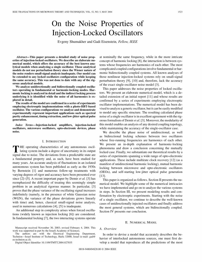
Fig. 1(a) describes the basic physical model.This is the well-known feedback model commonly used [2],
[8] to analyze different self-induced and interaction-imposedproperties of generic oscillators. This feedback structures hasbeen used to model numerous practical oscillators using of-the-shelf software packages [14].
The model we present is designed to self start from noise andmakes no assumptions on its final state or the evolutionary routereaching it. It includes all the nonlinear interaction mechanismspresent in real oscillators, which will be shown to be crucial foroscillator-coupling processes.
The topology of the model lends itself well to an anal-ysis based on the so-called transmission-line time-domaintreatment, extensively described in [15] and [16] and brieflyoutlined hereon.
The physical device to be analyzed is partitioned into sec-tions of equal group delay . Group delay is easily defined inthe linear regime and also be can treated in nonlinear phase el-ements [17].
Two voltage values are defined for each section (cell): in-cident voltages ( is the time-step number) andtheir respective scattered voltages . The scatteredand incident voltages of each cell are related to each other ac-cording to the physical process characterizing the cell. Time isadvanced by transforming the scattered voltage values of eachcell into the incident values of the next-in-order cell in the timestep .
The computational structure of the feedback oscillator withthe physical blocks partitioned into , equal group-delay seg-ments, is shown in Fig. 1(b). The duration of a single time stepis determined by the desired spectral bandwidth, whereas therepresentation of all electrical signals uses the baseband con-vention (real values). Hence, the time separation between twoconsecutive samples is , where stands for both thesampling frequency and signal bandwidth.
The required spectral bandwidth is dictated by the spectralcontent of the multiharmonic output signal. The number of sig-nificant harmonics depends on the nonlinearity of the gain el-ement, and the chosen bandwidth needs to be sufficiently wideso as to include all of them and avoid aliasing.
C. Noise Sources Modeling
The numerical model is self-starting from noise and, there-fore, requires a proper treatment of the random input signal.We consider only WGN sources, noting that the model can beeasily expanded to accommodate other noise contributions, in-cluding those that are cross-correlated between different portsof the model. Colored noise sources can significantly impactboth free-running and injection-locked oscillators, as has beenstudied using different formalisms and forms [18], [19]. How-ever, substantial qualitative understanding of the major factorsgoverning interlocked oscillator topologies is gained when onlyWGN is considered, as it typifies most autonomous systems [1].
To realize a WGN source, we start with uniformly distributedsamples generated by an algorithm called the “MersenneTwister” [20], which guarantees a large repetition cycle ofapproximately 2 1, good decorrelation between consec-utive bits, and relatively fast operation.
In order to achieve a Gaussian distribution of uniformrandom values, it is necessary to implement the correspondinginverse cumulative distribution function. As the Gaussiandistribution has no closed-form analytical-distribution function,this requires an intricate treatment, as outlined in [21].
The mean square value of noise samples ( ) was chosento equal the thermal noise voltage (Johnson noise), which isdefined as
(1)
SHUMAKHER AND EISENSTEIN: ON THE NOISE PROPERTIES OF INJECTION-LOCKED OSCILLATORS 1525
where is the bandwidth to be examined (equal to samplingfrequency ). Typical Johnson noise correlation at roomtemperature is on the picosecond time scale. Therefore, for theWGN to remain a valid mathematical model, we limit tothe range of tens of gigahertz. Higher sampling frequenciesrequire the implementation of a correlation mechanism for theacquired WGN samples. The present generic core structureimplemented one Johnson noise source with an value thatensures measurable perturbation levels in the oscillator output.
D. Detailed Description of the Core Blocks
The feedback loop is partitioned into segments, each playinga definite role and having a specific numeric implementation.
1) Gain Element: The most essential part of every regen-erative self-sustained system (which looses energy and, conse-quently, regains it by means of amplification) is a nonlinear gainelement. The intra-loop nonlinear gain is also responsible for theability to injection lock the oscillator to an incoming signal.
The mathematical realization of nonlinear gain in feedbackoscillator configurations is straightforward because of the timeseparation between the input and output signals stemming fromthe nonlinear function.
Gain saturation at high input signal powers, common to allamplifying media, is described by
(2)
The nonlinear function (2) yields only odd powers of . Eventerms must be introduced artificially so that the gain elementoutput voltage gets the form
(3)
To speedup calculations, the original value of is reused toproduce the final . Moreover, since in most real oscillators
, can be expanded into a polynomial form, whichalso contains highly reusable components.
2) Bandpass Filter (BPF) Implementation: The intra-cavityBPF is responsible for defining the fundamental frequency ofoscillations, it determines the quality of the generated signal,and dictates the ability to track injected perturbations. Allknown forms of BPFs are variations of an RLC combinationwhose Lorenzian transfer function is characterized by theresonance frequency and by an appropriate figure-of-meritto describe the resonance quality. A textbook definition of thequality is the ratio of its resonant frequency to its bandwidth,which is usually expressed in terms of energies ,with being the average stored energy stored and being theaverage dissipated power. However, the concept of an oscillator
is not suitable for use in analytical expressions [2] aimed at
calculations of power spectral densities (PSDs). An alternativefigure-of-merit is the group delay (i.e., the phase slope of theloop gain ) evaluated at resonance, which is related to
in simple RLC tanks [14]
(4)
This relation does not hold in more complex filtering schemes.The present numerical model does not concern itself with thenature of the figure-of-merit and the use of to qualify theresonance circuit is a pure notational issue.
The transfer function of an RLC tank
(5)
can be rewritten in the discrete time-domain form of the infi-nite impulse response (IIR) filter employing the bilinear trans-formation [22] shown in (6) at the bottom of this page, where
with and being the pre-wrapped qualityfactor and resonant frequency.
A new sample appears at the filter input in each time stepand an output sample is calculated, in real time, from the corre-sponding normalized ( ) difference equation
(7)
This technique, known as analog prototyping [22] is, of course,not limited to the exemplary RLC tank structure and can be usedfor any complex filtering scheme.
3) Implementation of the Feedback Chain: The feedbackchain models additional group delays within the oscillatingloop. Long intracavity transmission paths such as terminatedtransmission lines in microwave oscillators, long single-modefibers in OEOs [23], or any other source of linear phaseaccumulation actually define the oscillator quality, as shown innumerous works analyzing long group delays, as in an OEO.Long delays, while improving the spectral purity, reduce themode spacing, which may results in multimode behavior.
The simplest numerical realization of linear phase (constantgroup delay) is, of course, the first-in first-out (FIFO) structure,which delays an incoming sample at its front end by ,where is the number of FIFO cells and is the simulationtime step. A new input is placed in the front-end cell at the endof each time step and the output is delivered from the back-endcell. All the cells in between are advanced to their consecutiveneighbors.
Nonlinear phase (e.g., group velocity dispersion insingle-mode optical fibers) can be modeled using time-domaintechniques [17], which incorporate more complex individualcells based on IIR filter principles.
(6)
1526 IEEE TRANSACTIONS ON MICROWAVE THEORY AND TECHNIQUES, VOL. 52, NO. 5, MAY 2004
E. PSD Estimation and Data Storage
The objective of this model is to characterize an interlockedoscillator topology from the point-of-view of phase noise. Thestandard definition of phase noise is given in (8), shown at thebottom of this page [24], where is the phase spectraldensity in units of rad Hz.
Separating phase deviations from amplitude noise in an arbi-trary signal is a difficult, although possible, task [25]. Indeed,most laboratory instruments measure total PSD, which, in gen-eral, contains both phase and amplitude noise. For an oscillatoroutput signal, this issue is somewhat different in that amplitudefluctuations have a finite lifetime inside the oscillating loop and,hence, the frequency range close to the carrier does not containany amplitude noise. Therefore, PSDs in the spectral vicinity ofthe carrier comprises exclusively phase spectral densities.
The PSD of the numerically derived signals can be readilyestimated by the Periodogram method (basically a discreteFourier transform (DFT) on the sampled points), as explained in[26]. The desired frequency resolution determines the numberof points needed to be calculated in the time domain, where, inorder to support a spectral resolution of while sampling atthe frequency , one has to accumulate at leastpoints. A high spectral resolution is imperative from severalaspects, the two most important ones are as follows.
The requirement for a high spectral resolution originates firstfrom Demir’s analytical treatment of phase noise in a singleoscillator [3]. Considering only WGN sources, it is shown in[3] that the entire signal power spectrum can be characterizedby a single constant as follows:
(9)
The single harmonic PSD is, therefore, given by a Lorenzianfunction whose knee frequency is
(10)
Knowledge of a single-knee frequency completely characterizesthe signal spectrum since it reveals the constant. It is of out-most importance, therefore, to accurately deduce the knee fre-quency from the PSD, which requires, in turn, that the spectralresolution be higher than ( ). The constant isdetermined by the strength of the noise source and by the overallquality factor of the oscillator. In order to analyze high- sys-tems (whose is low) it is imperative to use a high spectralresolution.
Second, in order to derive a correct phase noise, one hasto normalize the PSD of each harmonic to the total power ofthat harmonic. In the expression for (9), the termmust be known exactly. In order for the numerical integra-tion to yield a correct result, one has to include a sufficient
Fig. 2. Low-resolution calculated spectrum of a 1.5-GHz Q = 5 oscillatorincluding several harmonics. The insert shows a 10-MHz span centered around1.5 GHz.
number of points, which are spectrally located below the kneefrequency. The reason is that ,but is unbounded. Hence, choosing only highfrequencies (above ) yields ( ), which resultsin —rendering ill-defined numericalintegration.
The previous paragraphs emphasize the need for both largebandwidth and high spectral resolution. In order to stress thedifficulty of meeting both, we consider the following example.Modeling a reasonably high-quality oscillator at 1 GHz requiresat least a 10-GHz sampling bandwidth. Even a moderate 10-Hzspectral resolution requires the accumulation of at least
samples. In order to perform frequency anal-ysis, the fast Fourier transform (FFT) operation requires to storeapproximately bytes Gb (for double-precision rep-resentation with 64 bit), which is impractical with conventionalRAM systems.
The only way to elevate this severe limitation is to performinitial data-processing routines in parallel with the simulationwithin the close wrapper layer.
1) Preliminary Data Processing: The storage limitation wasovercome in the present model using a time-domain decimationprocedure [22]. The entire sampled bandwidth is actually notneeded for the analysis since only a relatively narrow spectralwindow centered around the significant harmonics is used forthe calculation. Time-domain decimation selects only the rele-vant points, thereby dramatically reducing the storage needs.
An exemplary oscillator with a quality factor of op-erating at GHz has been analyzed and a low-reso-lution spectrum is shown Fig. 2. An insert describes a narrow10-MHz-wide spectral region around GHz, where thephase noise is analyzed. Returning to the example of the 10-GHzoscillator, operation within a 10-MHz band requires keeping
$Power density in one phase noise modulated sideband per hertz
Total signal power(8)
SHUMAKHER AND EISENSTEIN: ON THE NOISE PROPERTIES OF INJECTION-LOCKED OSCILLATORS 1527
track of only one sample in 1000 so that the required memoryvolume is reduced to a manageable level of several megabytes.
A simple reduction in the number of samples results in severesignal distortions due to aliasing. Therefore, data decimationmust be accompanied by filtering. If several bands are required,each must have an individual digital filter. Sharp filters call forhigh-order finite impulse response (FIR)/IIR chains, which usefrequent accessed RAM resulting in a vast increase in compu-tation time. The problem is overcome by converting the desiredspectral band into a complex envelope signal, and employingthe same filter for every required band.
The most efficient procedure is to calculate only those pointsneeded to support the desired resolution within the chosenspectral band—a technique known as polyphase filtering [22].Further improvements in terms of run-time minimization areachieved by the use of the efficient streaming single-instructionmultiple-data extensions [27], which significantly enhancecomputational parallelism.
By the end of the main simulation run, complex valuedsignals (streams of complex samples) are available for furtherprocessing.
2) PSD Calculation and Smoothing: This part is performedafter all the necessary data has been accumulated from the mainsimulation run. Since the total PSD of the oscillator is separatedinto harmonic bands, the DFT has to be performed separatelyfor each of the streams (harmonics). The DFT is realized usingRadix-2-based FFT available from [26]. The proposed code hasbeen rewritten to employ single-instruction multiple-data rou-tines for faster execution.
Finally, the issue of the model being self-starting from noisemust be addressed. The data accumulated in one pass representsbut one statistical route. In order to account for the numerousstatistical possibilities along which oscillations can evolve, it isnecessary to average the results from an ensemble of systems.This classifies the model as Monte Carlo type. As with all sim-ulations of this type, the larger the ensemble is, the smootherPSD will result.
III. NUMERICAL AND EXPERIMENTAL RESULTS
This section is devoted to numerical, as well as experimentalresults describing a large number of coupled oscillator config-urations. In the first step, we analyze a single generic oscil-lator using both our numerical model and the rigorous analyticalmodel [3]. We obtain identical results, thereby establishing theaccuracy of the simulation.
Next, we analyze a series of locked oscillator configurationsfor which no accurate analytical analysis is available. Themodular nature of the numerical model enables the analysis ofany locking topology while maintaining the accuracy of thesingle-oscillator case. The numerical predictions are confirmedby experiments employing electrooptical oscillator configu-rations based on InP bipolar heterojunction photo-transistors(photo-HBTs).
A. Single-Oscillator Analysis
The first results we present are for a single generic oscillatorwith GHz and . The noise injection level is ad-
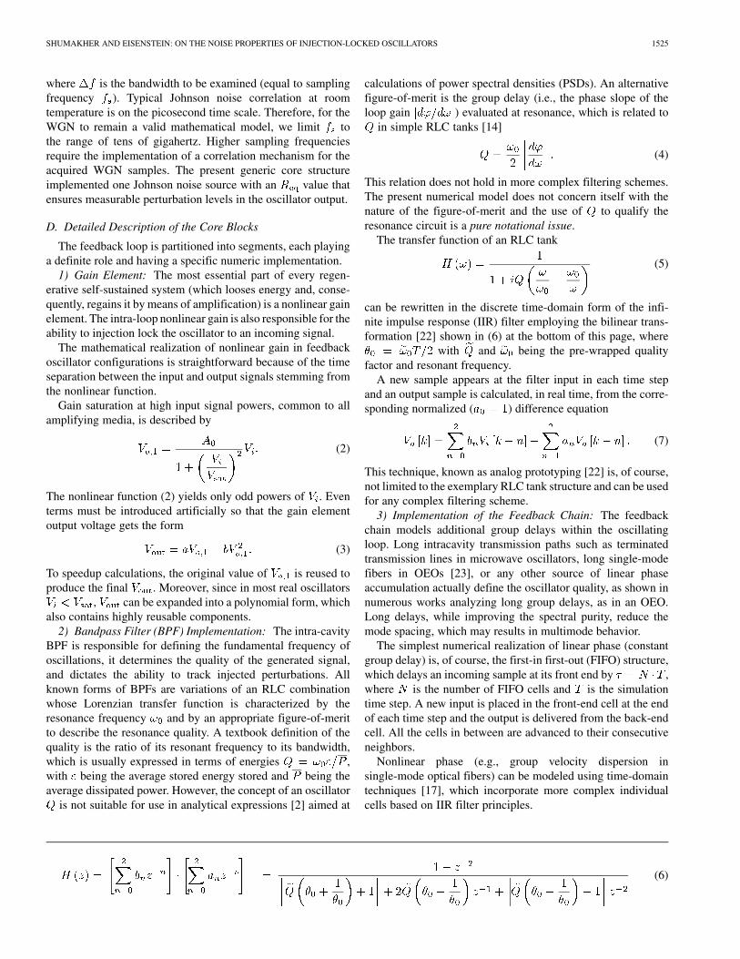
Fig. 3. Calculated jitter determination in a 1.5-GHz Q = 5 oscillator.(a) Threshold crossing time versus number of crossing. (b) Crossing-timevariance versus time; simulated results and a linear fit are shown.
justed to yield a reasonable amount of phase noise and ensuringthat the knee frequency is observable with the spectral resolu-tion we employed.
The final objective of the simulation is, of course, the PSDof the oscillator. The characterizing parameter [defined in (9)]has to be found first since it is needed for a proper comparisonbetween the simulation and analytically calculated PSD. Thereare several ways to obtain the -parameter, the most applicablehere is to directly track the crossing (transition) time variance[28]. This is achieved by recording, for an ensemble of oscilla-tors, the time at which the output signal crosses an arbitrarilychosen threshold and then calculating the variance of the distri-bution in crossing times.
Fig. 3(a) shows the evolution of crossing times calculatedby our numerical model. It is essentially a straight line, whichmeans that the transitions are, on average, equally separated intime (the average time period is constant). A linear fit of thegraph in Fig. 3(a) results in a time period corresponding to arepetition rate of 1.5 GHz.
The time evolution of the variance in the crossing-time dis-tribution is shown in Fig. 3(b), which is also a straight line. Theanalytical model [3], [28] predicts that the variance in crossingtimes increases linearly with time, as dictated by the Wiener
1528 IEEE TRANSACTIONS ON MICROWAVE THEORY AND TECHNIQUES, VOL. 52, NO. 5, MAY 2004
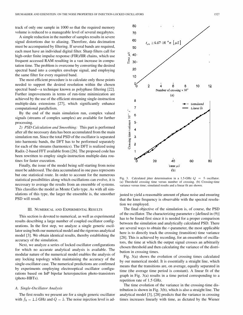
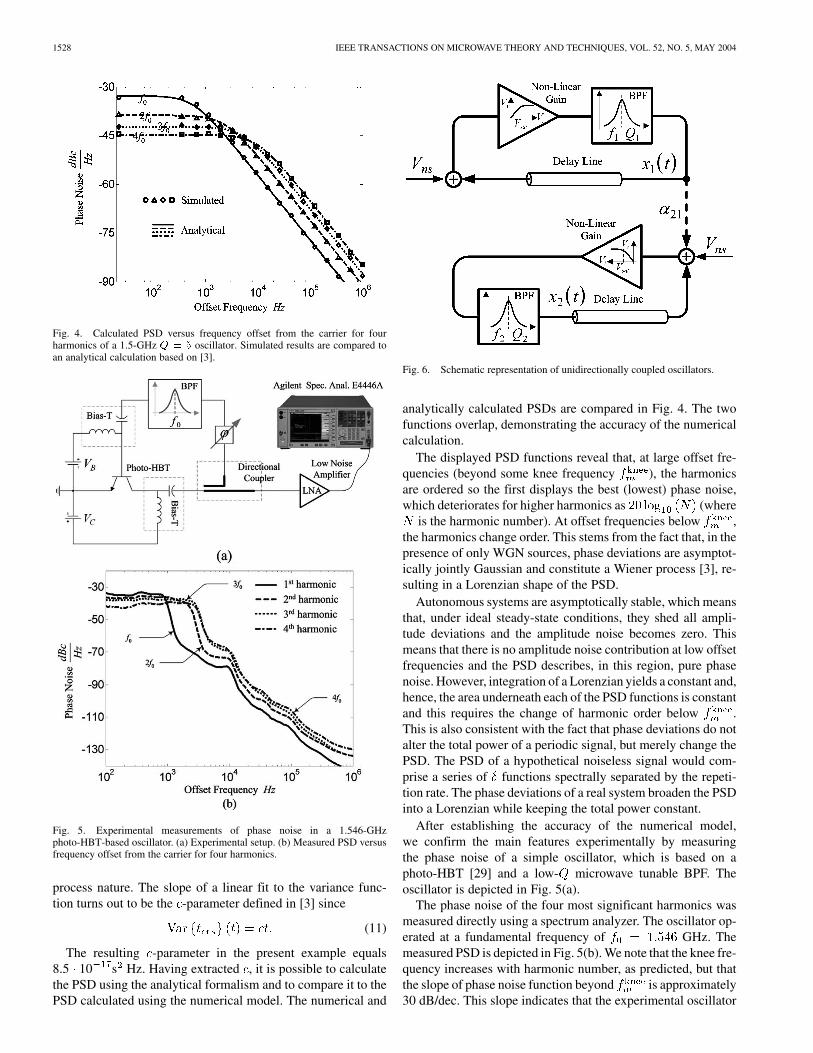
Fig. 4. Calculated PSD versus frequency offset from the carrier for fourharmonics of a 1.5-GHz Q = 5 oscillator. Simulated results are compared toan analytical calculation based on [3].
Fig. 5. Experimental measurements of phase noise in a 1.546-GHzphoto-HBT-based oscillator. (a) Experimental setup. (b) Measured PSD versusfrequency offset from the carrier for four harmonics.
process nature. The slope of a linear fit to the variance func-tion turns out to be the -parameter defined in [3] since
(11)
The resulting -parameter in the present example equals8.5 10 s Hz. Having extracted , it is possible to calculatethe PSD using the analytical formalism and to compare it to thePSD calculated using the numerical model. The numerical and
Fig. 6. Schematic representation of unidirectionally coupled oscillators.
analytically calculated PSDs are compared in Fig. 4. The twofunctions overlap, demonstrating the accuracy of the numericalcalculation.
The displayed PSD functions reveal that, at large offset fre-quencies (beyond some knee frequency ), the harmonicsare ordered so the first displays the best (lowest) phase noise,which deteriorates for higher harmonics as (where
is the harmonic number). At offset frequencies below ,the harmonics change order. This stems from the fact that, in thepresence of only WGN sources, phase deviations are asymptot-ically jointly Gaussian and constitute a Wiener process [3], re-sulting in a Lorenzian shape of the PSD.
Autonomous systems are asymptotically stable, which meansthat, under ideal steady-state conditions, they shed all ampli-tude deviations and the amplitude noise becomes zero. Thismeans that there is no amplitude noise contribution at low offsetfrequencies and the PSD describes, in this region, pure phasenoise. However, integration of a Lorenzian yields a constant and,hence, the area underneath each of the PSD functions is constantand this requires the change of harmonic order below .This is also consistent with the fact that phase deviations do notalter the total power of a periodic signal, but merely change thePSD. The PSD of a hypothetical noiseless signal would com-prise a series of functions spectrally separated by the repeti-tion rate. The phase deviations of a real system broaden the PSDinto a Lorenzian while keeping the total power constant.
After establishing the accuracy of the numerical model,we confirm the main features experimentally by measuringthe phase noise of a simple oscillator, which is based on aphoto-HBT [29] and a low- microwave tunable BPF. Theoscillator is depicted in Fig. 5(a).
The phase noise of the four most significant harmonics wasmeasured directly using a spectrum analyzer. The oscillator op-erated at a fundamental frequency of GHz. Themeasured PSD is depicted in Fig. 5(b). We note that the knee fre-quency increases with harmonic number, as predicted, but thatthe slope of phase noise function beyond is approximately30 dB/dec. This slope indicates that the experimental oscillator
SHUMAKHER AND EISENSTEIN: ON THE NOISE PROPERTIES OF INJECTION-LOCKED OSCILLATORS 1529
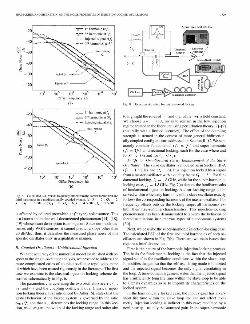
Fig. 7. Calculated PSD versus frequency offset from the carrier for the first andthird harmonics in a unidirectionally coupled system. (a) Q = 50, Q = 5,f = f = 1:5 GHz. (b) Q = 50, Q = 5, f = 4:5 GHz, f = 1:5 GHz.
is affected by colored (nonwhite type) noise source. Thisis a known and rather well-documented phenomenon [14], [18],[19] whose exact description is ambiguous. Since our model as-sumes only WGN sources, it cannot predict a slope other than20 dB/dec, thus, it describes the measured phase noise of thisspecific oscillator only in a qualitative manner.
B. Coupled Oscillators—Unidirectional Injection
With the accuracy of the numerical model established with re-spect to the single-oscillator analysis, we proceed to address themore complicated cases of coupled oscillator topologies, noneof which have been treated rigorously in the literature. The firstcase we examine is the classical injection-locking scheme de-scribed schematically in Fig. 6.
The parameters characterizing the two oscillators are , ,, and and the coupling coefficient . Classical injec-
tion locking theory, first introduced by Adler [6], states that theglobal behavior of the locked system is governed by the ratio
and that determines the locking range. In this sec-tion, we disregard the width of the locking range and rather aim
Fig. 8. Experimental setup for unidirectional locking.
to highlight the roles of and , while is held constant.We choose so as to remain in the low injectionregime treated in the literature using perturbation theory [7]–[9](naturally with a limited accuracy). The effect of the couplingstrength is treated in the context of more general bidirection-ally coupled configurations addressed in Section III-C. We sep-arately consider fundamental ( ) and super-harmonic( ) unidirectional locking, each for the case where andfor and for .
1) —Spectral Purity Enhancement of the SlaveOscillator: The slave oscillator is modeled as in Section III-A( GHz and ). It is injection locked by a signalfrom a master oscillator with a quality factor . For fun-damental locking, GHz, while for the super-harmonic-locking case, GHz. Fig. 7(a) depicts the familiar resultsof fundamental injection locking. A clear locking range is ob-served within which any harmonic of the slave oscillator exactlyfollows the corresponding harmonic of the master oscillator. Forfrequency offsets outside the locking range, all harmonics ex-hibit their free-running characteristics. This injection-lockingphenomenon has been demonstrated to govern the behavior offorced oscillations in numerous types of autonomous systems[30].
Next, we describe the super-harmonic injection-locking case.The calculated PSD of the first and third harmonics of both os-cillators are shown in Fig. 7(b). There are two main issues thatrequire a brief discussion.
First is the nature of the harmonic injection-locking process.The basis for fundamental locking is the fact that the injectedsignal satisfies the oscillation conditions within the slave loop.It modifies the gain so that the self-oscillating mode is inhibitedand the injected signal becomes the only signal circulating inthe loop. A time-domain argument states that the injected signalhas a sufficiently long life time within the slave loop to be ableto alter its dynamics so as to imprint its characteristics on thelocked system.
In the harmonically locked case, the input signal has a veryshort life time within the slave loop and can not affect it di-rectly. Injection locking is indirect in this case; mediated by anonlinearity—usually the saturated gain. In the super-harmonic
1530 IEEE TRANSACTIONS ON MICROWAVE THEORY AND TECHNIQUES, VOL. 52, NO. 5, MAY 2004
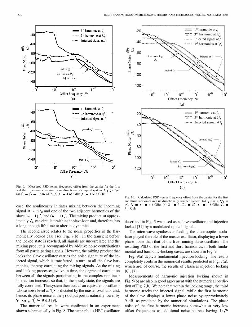
Fig. 9. Measured PSD versus frequency offset from the carrier for the firstand third harmonics locking in unidirectionally coupled system. Q > Q .(a) f = f = 1:546 GHz. (b) f = 4:64 GHz, f = 1:546GHz.
case, the nonlinearity initiates mixing between the incomingsignal at and one of the two adjacent harmonics of theslave and . The mixing product, at approx-imately , can circulate within the slave loop and, therefore, hasa long enough life time to alter its dynamics.
The second issue relates to the noise properties in the har-monically locked case [see Fig. 7(b)]. In the transient beforethe locked state is reached, all signals are uncorrelated and themixing product is accompanied by additive noise contributionsfrom all participating signals. However, the mixing product thatlocks the slave oscillator carries the noise signature of the in-jected signal, which is transferred, in turn, to all the slave har-monics, thereby correlating the mixing signals. As the mixingand locking processes evolve in time, the degree of correlationbetween all the signals participating in the complex nonlinearinteraction increases so that, in the steady state, the signals arefully correlated. The system then acts as an equivalent oscillatorwhose noise level at is dictated by the master oscillator and,hence, its phase noise at the output port is naturally lower by
dB [9].The numerical results were confirmed in an experiment
shown schematically in Fig. 8. The same photo-HBT oscillator
Fig. 10. Calculated PSD versus frequency offset from the carrier for the firstand third harmonics in a unidirectionally coupled system. (a) Q = 5, Q =
50, f = f = 1:5 GHz. (b) Q = 5, Q = 50, f = 4:5 GHz, f =
1:5 GHz.
described in Fig. 5 was used as a slave oscillator and injectionlocked [31] by a modulated optical signal.
The microwave synthesizer feeding the electrooptic modu-lator played the role of the master oscillator, displaying a lowerphase noise than that of the free-running slave oscillator. Theresulting PSD of the first and third harmonics, in both funda-mental and harmonic-locking cases, are shown in Fig. 9.
Fig. 9(a) depicts fundamental injection locking. The resultscompletely confirm the numerical results predicted in Fig. 7(a),which are, of course, the results of classical injection locking[6], [7].
Measurements of harmonic injection locking shown inFig. 9(b) are also in good agreement with the numerical predic-tion of Fig. 7(b). We note that within the locking range, the thirdharmonic tracks the injected signal, while the first harmonicof the slave displays a lower phase noise by approximately9 dB, as predicted by the numerical simulations. The phasenoise of the first harmonic increases somewhat at very lowoffset frequencies as additional noise sources having
SHUMAKHER AND EISENSTEIN: ON THE NOISE PROPERTIES OF INJECTION-LOCKED OSCILLATORS 1531
Fig. 11. Experimental setup for multirate timing extraction (taken from [12]).
characteristics and stemming from the photo-transistor maskthe basic oscillator noise behavior.
2) —Master Oscillator Tracking: The second uni-directional locking configuration deals with the cases where thespectral purity of the injected signal is lower than that of theslave oscillator . This situation is modeled with themaster oscillator having a quality factor and the slaveoscillator characterized by .
Fig. 10(a) portrays the results of fundamental locking.Within the locking range, corresponding harmonics coincide,which means that the spectral purity of the slave oscillatordeteriorates as it attains the properties of the input signal. Thevarious harmonics display their free-running characteristicsoutside the locking range. Similar results are obtained in theharmonic-locking case, as shown in Fig. 10(b). The third har-monics of the slave oscillator follows (within the locking range)the phase noise of the first incoming harmonic, while the phasenoise of the first slave harmonic is lower by approximately
dB.The numerical results of Fig. 10 describe tracking of an in-
coming noise-carrying signal, as in timing extraction of digitalreceivers [32]. An experimental demonstration of multibit-ratetiming extraction using these concepts was first reported byLasri et al. [12].
Fig. 11, taken from [12], shows the experimental set up withwhich the timing of return to zero (RZ) data streams at 10 and40 GBit/s was extracted by optical injection locking of a single10-GHz photo-HBT-based oscillator.
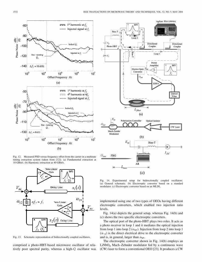
Fig. 12, also taken from [12], describes the timing extrac-tion results. Clock recovery for the 10-GBit/s data stream, isdescribed in Fig. 12(a). The PSD of the first oscillator harmonicis shown for free-running, as well as locked conditions, togetherwith the injected clock component. Within the locking range,the oscillator tracks the incoming data stream, hence, producinga synchronization reference for data sampling. Fig. 12(b) de-
scribes clock recovery of a 40-GBit/s stream using harmonicinjection locking of the 10-GHz oscillator. Within the lockingrange, the fourth harmonic tracks closely the injected signal with
GHz, thereby producing the required sampling clock.At the same time, the first harmonic (at GHz) displaysa lower phase noise by approximately 12 dB, as expected from
dB, consistent once more with the theoreticalpredictions.
C. Coupled Oscillator—Bidirectional Injection
The most general configuration of a two coupled oscillatorssystem comprises bidirectional mutual coupling. Some aspectsof the special case where nearly identical oscillators are mutu-ally coupled have been treated in the literature [33]–[35]. Weanalyze a generalized configuration whose topology is shownin Fig. 13.
A system of bidirectionally coupled oscillators is character-ized by , , , and the relative injection strength
, where and are once more chosen to besmall in order to ensure the low injection regime. Unlike in theunidirectional case, where quantifies the locking range, buthas no effect on the noise, dictates here the cumulative noiseproperties of the locked system.
A very large number of mutually coupled configurations arepossible because of the abundant degrees of freedom. We con-centrate here on two that represent an entire class of systems andthat complement the unidirectional configurations presented inSection III-B. Additional configurations can be easily analyzedusing the same numerical envelope.
We treat fundamental ( ) and harmonic ( ) locking,while fixing the quality factors to be and andletting to take on discrete values in the range from 0.01 to 100.
Several experiments were carried out to substantiate the con-clusions of the numerical simulations. The experimental setup
1532 IEEE TRANSACTIONS ON MICROWAVE THEORY AND TECHNIQUES, VOL. 52, NO. 5, MAY 2004
Fig. 12. Measured PSD versus frequency offset from the carrier in a multiratetiming extraction system (taken from [12]). (a) Fundamental extraction at10 GBit/s. (b) Harmonic extraction at 40 GBit/s.
Fig. 13. Schematic representation of bidirectionally coupled oscillators.
comprised a photo-HBT-based microwave oscillator of rela-tively poor spectral purity, whereas a high- oscillator was
Fig. 14. Experimental setup for bidirectionally coupled oscillators.(a) General schematic. (b) Electrooptic converter based on a standardmodulator. (c) Electrooptic converter based on an MLDL.
implemented using one of two types of OEOs having differentelectrooptic converters, which enabled two injection ratiolevels.
Fig. 14(a) depicts the general setup, whereas Fig. 14(b) and(c) shows the two specific electrooptic converters.
The optical port of the photo-HBT plays two roles. It acts asa photo receiver in loop 1 and it mediates the optical injectionfrom loop 1 into loop 2 ( ). Injection from loop 2 into loop 1( ) is the direct electrical drive to the electrooptic converterand is, in general, larger than .
The electrooptic converter shown in Fig. 14(b) employs anLiNbO Mach–Zehnder modulator fed by a continuous wave(CW) laser to form a conventional OEO [23]. It produces a CW
SHUMAKHER AND EISENSTEIN: ON THE NOISE PROPERTIES OF INJECTION-LOCKED OSCILLATORS 1533
Fig. 15. Calculated PSD versus frequency offset from the carrier for the first harmonic in fundamental bidirectionally locked oscillators.Q = 50,Q = 5, andf = f = 1:5 GHz. (a) � = 0:2. (b) � = 1. (c) � = 5. (d) Phase noise at 10-kHz offset as a function of �.
electrical signal at approximately . The second electroopticconverter uses a mode-locked diode laser (MLDL) instead ofthe modulator. This OEO generates short optical pulses withexcellent timing jitter at a repetition rate of together with ahigh purity electrical signal [13].
1) Fundamental Locking: Calculated PSDs for various in-jection ratios of fundamental ( ) bidirectional couplingare shown in Fig. 15. Fig. 15(a) describes the behavior of thefirst harmonics for , namely, when the injection fromthe high- oscillator dominates. behaves much as in itsfree-running state and within the locking range, the phase noiseof improves and coincides with . These results resemblethose of the unidirectional case depicted in Fig. 7(a).
We also calculated the third harmonic PSDs for the two os-cillators. The results [not shown in Fig. 15(a)] reveal the samebehavior as that of the first harmonics, except that in each case,the overall noise is higher by 9 dB.
As the injection ratio grows, the influence of increases andat , the phase noise of is larger than in its free-running
state. Fig. 15(b) shows that, within the locking range, follows, as expected. A similar behavior is found once more for the
corresponding third harmonics, whose noise level is higher by9 dB. For larger values, the effect of on the spectral qualityof the locked system increases further.
Fig. 15(c) shows that, for , the phase noise of the firstharmonic of reaches a level that is only slightly lower thanthat of the free-running . This means that dominates andthe higher quality oscillator has but a minor effect on theproperties of the locked system. As in the cases of and
, the corresponding third harmonics (not shown) behavesimilarly, except that their overall noise level is higher.
The dependence on of the locked system is described inFig. 15(d) by means of the calculated phase noise of the firstharmonic at 10-kHz offset from the carrier. For small values of
, the locked system attains the noise of the free-running oscil-lator , whereas for larger values, phase noise of the lockedsystem increases as the contribution of grows. In the limit,
1534 IEEE TRANSACTIONS ON MICROWAVE THEORY AND TECHNIQUES, VOL. 52, NO. 5, MAY 2004
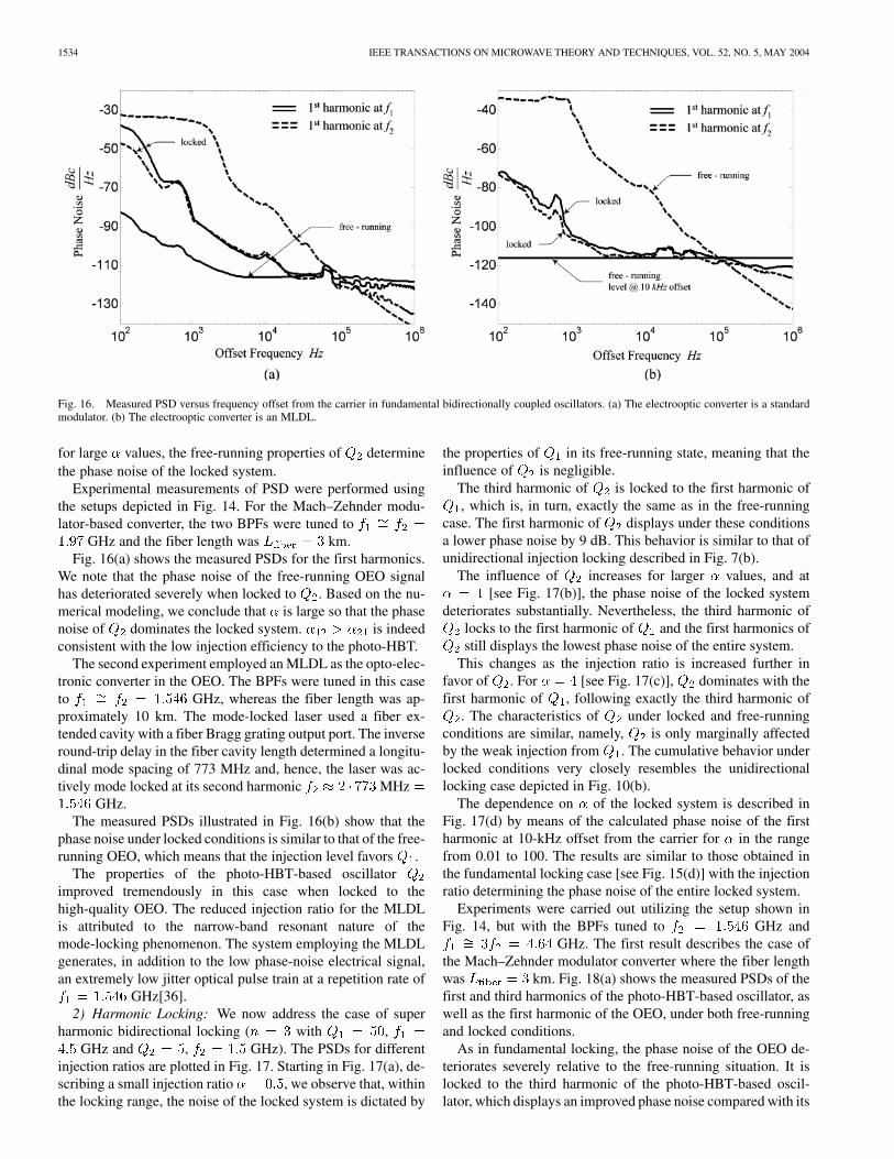
Fig. 16. Measured PSD versus frequency offset from the carrier in fundamental bidirectionally coupled oscillators. (a) The electrooptic converter is a standardmodulator. (b) The electrooptic converter is an MLDL.
for large values, the free-running properties of determinethe phase noise of the locked system.
Experimental measurements of PSD were performed usingthe setups depicted in Fig. 14. For the Mach–Zehnder modu-lator-based converter, the two BPFs were tuned to
GHz and the fiber length was km.Fig. 16(a) shows the measured PSDs for the first harmonics.
We note that the phase noise of the free-running OEO signalhas deteriorated severely when locked to . Based on the nu-merical modeling, we conclude that is large so that the phasenoise of dominates the locked system. is indeedconsistent with the low injection efficiency to the photo-HBT.
The second experiment employed an MLDL as the opto-elec-tronic converter in the OEO. The BPFs were tuned in this caseto GHz, whereas the fiber length was ap-proximately 10 km. The mode-locked laser used a fiber ex-tended cavity with a fiber Bragg grating output port. The inverseround-trip delay in the fiber cavity length determined a longitu-dinal mode spacing of 773 MHz and, hence, the laser was ac-tively mode locked at its second harmonic MHz
GHz.The measured PSDs illustrated in Fig. 16(b) show that the
phase noise under locked conditions is similar to that of the free-running OEO, which means that the injection level favors .
The properties of the photo-HBT-based oscillatorimproved tremendously in this case when locked to thehigh-quality OEO. The reduced injection ratio for the MLDLis attributed to the narrow-band resonant nature of themode-locking phenomenon. The system employing the MLDLgenerates, in addition to the low phase-noise electrical signal,an extremely low jitter optical pulse train at a repetition rate of
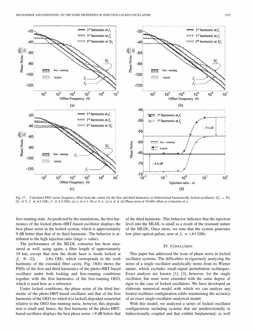
GHz[36].2) Harmonic Locking: We now address the case of super
harmonic bidirectional locking ( with ,GHz and , GHz). The PSDs for different
injection ratios are plotted in Fig. 17. Starting in Fig. 17(a), de-scribing a small injection ratio , we observe that, withinthe locking range, the noise of the locked system is dictated by
the properties of in its free-running state, meaning that theinfluence of is negligible.
The third harmonic of is locked to the first harmonic of, which is, in turn, exactly the same as in the free-running
case. The first harmonic of displays under these conditionsa lower phase noise by 9 dB. This behavior is similar to that ofunidirectional injection locking described in Fig. 7(b).
The influence of increases for larger values, and at[see Fig. 17(b)], the phase noise of the locked system
deteriorates substantially. Nevertheless, the third harmonic oflocks to the first harmonic of and the first harmonics ofstill displays the lowest phase noise of the entire system.
This changes as the injection ratio is increased further infavor of . For [see Fig. 17(c)], dominates with thefirst harmonic of , following exactly the third harmonic of
. The characteristics of under locked and free-runningconditions are similar, namely, is only marginally affectedby the weak injection from . The cumulative behavior underlocked conditions very closely resembles the unidirectionallocking case depicted in Fig. 10(b).
The dependence on of the locked system is described inFig. 17(d) by means of the calculated phase noise of the firstharmonic at 10-kHz offset from the carrier for in the rangefrom 0.01 to 100. The results are similar to those obtained inthe fundamental locking case [see Fig. 15(d)] with the injectionratio determining the phase noise of the entire locked system.
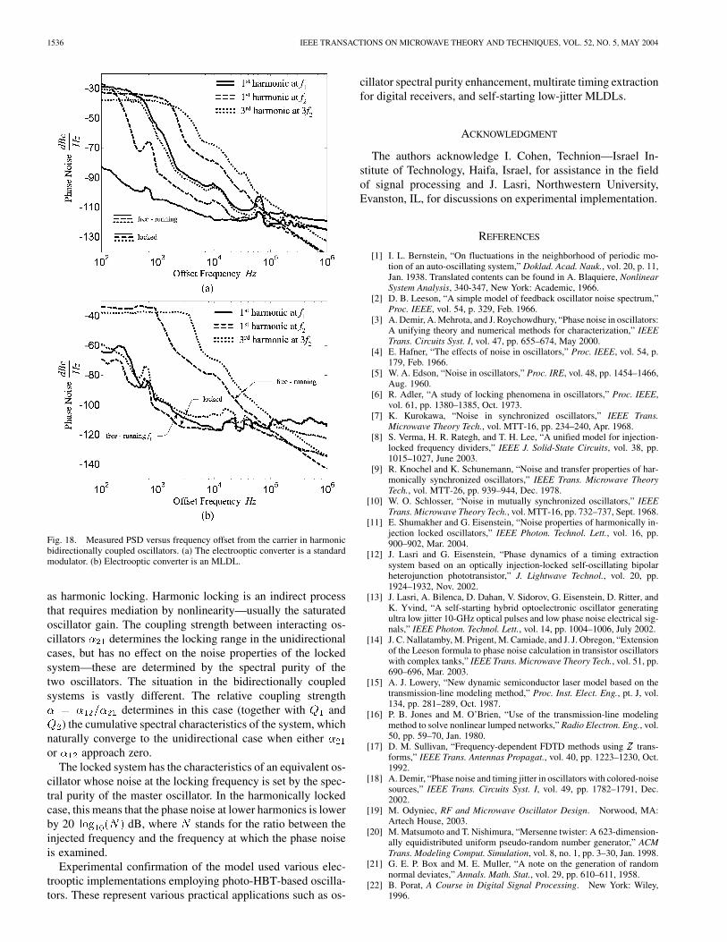
Experiments were carried out utilizing the setup shown inFig. 14, but with the BPFs tuned to GHz and
GHz. The first result describes the case ofthe Mach–Zehnder modulator converter where the fiber lengthwas km. Fig. 18(a) shows the measured PSDs of thefirst and third harmonics of the photo-HBT-based oscillator, aswell as the first harmonic of the OEO, under both free-runningand locked conditions.
As in fundamental locking, the phase noise of the OEO de-teriorates severely relative to the free-running situation. It islocked to the third harmonic of the photo-HBT-based oscil-lator, which displays an improved phase noise compared with its
SHUMAKHER AND EISENSTEIN: ON THE NOISE PROPERTIES OF INJECTION-LOCKED OSCILLATORS 1535
Fig. 17. Calculated PSD versus frequency offset from the carrier for the first and third harmonics in bidirectional harmonically locked oscillators. Q = 50,Q = 5, f = 4:5 GHz, f = 1:5 GHz. (a) � = 0:5. (b) � = 1. (c) � = 4. (d) Phase noise at 10-kHz offset as a function of �.
free-running state. As predicted by the simulations, the first har-monics of the locked photo-HBT-based oscillator displays thebest phase noise in the locked system, which is approximately9 dB better than that of its third harmonic. The behavior is at-tributed to the high injection ratio (large value).
The performance of the MLDL converter has been mea-sured as well, using again, a fiber length of approximately10 km, except that now the diode laser is mode locked at
GHz, which corresponds to the sixthharmonic of the extended fiber cavity. Fig. 18(b) shows thePSDs of the first and third harmonics of the photo-HBT-basedoscillator under both locking and free-running conditionstogether with the first harmonics of the free-running OEO,which is used here as a reference.
Under locked conditions, the phase noise of the third har-monic of the photo-HBT-based oscillator and that of the firstharmonic of the OEO (to which it is locked) degraded somewhatrelative to the OEO free-running noise, however, this degrada-tion is small and, hence, the first harmonic of the photo-HBT-based oscillator displays the best phase noise 9 dB below that
of the third harmonic. This behavior indicates that the injectionlevel into the MLDL is small as a result of the resonant natureof the MLDL. Once more, we note that the system generateslow-jitter optical pulses, now at GHz.
IV. CONCLUSION
This paper has addressed the issue of phase noise in lockedoscillator systems. The difficulties in rigorously analyzing thenoise of a single oscillator analytically stems from its Wienernature, which excludes small-signal perturbation techniques.Exact analysis are known [1], [3], however, for the singleoscillator, but none were extended with the same degree ofrigor to the case of locked oscillators. We have developed anelaborate numerical model with which we can analyze anylocked oscillator configuration while maintaining the accuracyof an exact single-oscillator analytical model.
With this model, we analyzed a series of locked oscillatorconfigurations including systems that are unidirectionally orbidirectionally coupled and that exhibit fundamental, as well
1536 IEEE TRANSACTIONS ON MICROWAVE THEORY AND TECHNIQUES, VOL. 52, NO. 5, MAY 2004
Fig. 18. Measured PSD versus frequency offset from the carrier in harmonicbidirectionally coupled oscillators. (a) The electrooptic converter is a standardmodulator. (b) Electrooptic converter is an MLDL.
as harmonic locking. Harmonic locking is an indirect processthat requires mediation by nonlinearity—usually the saturatedoscillator gain. The coupling strength between interacting os-cillators determines the locking range in the unidirectionalcases, but has no effect on the noise properties of the lockedsystem—these are determined by the spectral purity of thetwo oscillators. The situation in the bidirectionally coupledsystems is vastly different. The relative coupling strength
determines in this case (together with and) the cumulative spectral characteristics of the system, which
naturally converge to the unidirectional case when eitheror approach zero.
The locked system has the characteristics of an equivalent os-cillator whose noise at the locking frequency is set by the spec-tral purity of the master oscillator. In the harmonically lockedcase, this means that the phase noise at lower harmonics is lowerby 20 dB, where stands for the ratio between theinjected frequency and the frequency at which the phase noiseis examined.
Experimental confirmation of the model used various elec-trooptic implementations employing photo-HBT-based oscilla-tors. These represent various practical applications such as os-
cillator spectral purity enhancement, multirate timing extractionfor digital receivers, and self-starting low-jitter MLDLs.
ACKNOWLEDGMENT
The authors acknowledge I. Cohen, Technion—Israel In-stitute of Technology, Haifa, Israel, for assistance in the fieldof signal processing and J. Lasri, Northwestern University,Evanston, IL, for discussions on experimental implementation.
REFERENCES
[1] I. L. Bernstein, “On fluctuations in the neighborhood of periodic mo-tion of an auto-oscillating system,” Doklad. Acad. Nauk., vol. 20, p. 11,Jan. 1938. Translated contents can be found in A. Blaquiere, NonlinearSystem Analysis, 340-347, New York: Academic, 1966.
[2] D. B. Leeson, “A simple model of feedback oscillator noise spectrum,”Proc. IEEE, vol. 54, p. 329, Feb. 1966.
[3] A. Demir, A. Mehrota, and J. Roychowdhury, “Phase noise in oscillators:A unifying theory and numerical methods for characterization,” IEEETrans. Circuits Syst. I, vol. 47, pp. 655–674, May 2000.
[4] E. Hafner, “The effects of noise in oscillators,” Proc. IEEE, vol. 54, p.179, Feb. 1966.
[5] W. A. Edson, “Noise in oscillators,” Proc. IRE, vol. 48, pp. 1454–1466,Aug. 1960.
[6] R. Adler, “A study of locking phenomena in oscillators,” Proc. IEEE,vol. 61, pp. 1380–1385, Oct. 1973.
[7] K. Kurokawa, “Noise in synchronized oscillators,” IEEE Trans.Microwave Theory Tech., vol. MTT-16, pp. 234–240, Apr. 1968.
[8] S. Verma, H. R. Rategh, and T. H. Lee, “A unified model for injection-locked frequency dividers,” IEEE J. Solid-State Circuits, vol. 38, pp.1015–1027, June 2003.
[9] R. Knochel and K. Schunemann, “Noise and transfer properties of har-monically synchronized oscillators,” IEEE Trans. Microwave TheoryTech., vol. MTT-26, pp. 939–944, Dec. 1978.
[10] W. O. Schlosser, “Noise in mutually synchronized oscillators,” IEEETrans. Microwave Theory Tech., vol. MTT-16, pp. 732–737, Sept. 1968.
[11] E. Shumakher and G. Eisenstein, “Noise properties of harmonically in-jection locked oscillators,” IEEE Photon. Technol. Lett., vol. 16, pp.900–902, Mar. 2004.
[12] J. Lasri and G. Eisenstein, “Phase dynamics of a timing extractionsystem based on an optically injection-locked self-oscillating bipolarheterojunction phototransistor,” J. Lightwave Technol., vol. 20, pp.1924–1932, Nov. 2002.
[13] J. Lasri, A. Bilenca, D. Dahan, V. Sidorov, G. Eisenstein, D. Ritter, andK. Yvind, “A self-starting hybrid optoelectronic oscillator generatingultra low jitter 10-GHz optical pulses and low phase noise electrical sig-nals,” IEEE Photon. Technol. Lett., vol. 14, pp. 1004–1006, July 2002.
[14] J. C. Nallatamby, M. Prigent, M. Camiade, and J. J. Obregon, “Extensionof the Leeson formula to phase noise calculation in transistor oscillatorswith complex tanks,” IEEE Trans. Microwave Theory Tech., vol. 51, pp.690–696, Mar. 2003.
[15] A. J. Lowery, “New dynamic semiconductor laser model based on thetransmission-line modeling method,” Proc. Inst. Elect. Eng., pt. J, vol.134, pp. 281–289, Oct. 1987.
[16] P. B. Jones and M. O’Brien, “Use of the transmission-line modelingmethod to solve nonlinear lumped networks,” Radio Electron. Eng., vol.50, pp. 59–70, Jan. 1980.
[17] D. M. Sullivan, “Frequency-dependent FDTD methods using Z trans-forms,” IEEE Trans. Antennas Propagat., vol. 40, pp. 1223–1230, Oct.1992.
[18] A. Demir, “Phase noise and timing jitter in oscillators with colored-noisesources,” IEEE Trans. Circuits Syst. I, vol. 49, pp. 1782–1791, Dec.2002.
[19] M. Odyniec, RF and Microwave Oscillator Design. Norwood, MA:Artech House, 2003.
[20] M. Matsumoto and T. Nishimura, “Mersenne twister: A 623-dimension-ally equidistributed uniform pseudo-random number generator,” ACMTrans. Modeling Comput. Simulation, vol. 8, no. 1, pp. 3–30, Jan. 1998.
[21] G. E. P. Box and M. E. Muller, “A note on the generation of randomnormal deviates,” Annals. Math. Stat., vol. 29, pp. 610–611, 1958.
[22] B. Porat, A Course in Digital Signal Processing. New York: Wiley,1996.
SHUMAKHER AND EISENSTEIN: ON THE NOISE PROPERTIES OF INJECTION-LOCKED OSCILLATORS 1537
[23] X. S. Yao and L. Maleki, “Optoelectronic microwave oscillator,” J. Opt.Soc. Amer. B, Opt. Phys., vol. 13, no. 8, pp. 1725–1735, 1996.
[24] E. S. Ferre-Pikal et al., “Draft revision of IEEE STD 1139–1988 stan-dard definition of physical quantities for fundamental frequency andtime metrology random instabilities,” in Proc. Int. Freq. Control Symp.,May 1997, pp. 338–357.
[25] “Phase noise characterization of microwave oscillators: Frequency dis-crimination method,” Hewlett-Packard, Palo Alto, CA, Product Note11729C-2, Sept. 1985.
[26] W. H. Press et al., Numerical Recipes in C: The Art of Scientific Com-puting, 2nd ed. Cambridge, MA: Cambridge Univ. Press, 1992.
[27] IA-32 Intel® Architecture Optimization Reference Manual, IntelCorporation, Santa Clara, CA. [Online]. Available: http://www://devel-oper.intel.com.
[28] A. Demir and A. L. Sangiovanni-Vincentelli, “Simulation and modelingof phase noise in open loop oscillators,” in IEEE Custom Integrated Cir-cuits Conf., 1996, pp. 453–456.
[29] D. Ritter, B. Sheinman, V. Sidorov, S. Cohen, A. Gavrilov, Y. Vered, G.Zohar, and J. Lasri, “Optimization of InP/GaInAs heterojunction bipolartransistors and phototransistors,” in Proc. Microwave Photonics, Nov.2002, pp. 337–340.
[30] A. E. Siegman, Lasers. Herndon, VA: Univ. Sci. Books, 1986, pp.1129–1148.
[31] J. Lasri, A. Bilenca, G. Eisenstein, and D. Ritter, “Optoelectronicmixing, modulation and injection locking in millimeter-wave self-oscil-lating InP/InGaAs heterojunction bipolar photo transistors: Single anddual transistor configurations,” IEEE Trans. Microwave Theory Tech.,vol. 49, pp. 1934–1939, Oct. 2001.
[32] W. R. Benett, “Statistics of regenerative digital transmission,” Bell Syst.Tech. J., vol. 37, pp. 1501–1542, Nov. 1958.
[33] A. Bannai and F. Farzaneh, “Output power variations in two mutuallycoupled microwave oscillators and the effect of nonlinear reactance onthe locking bandwidth,” Proc. Inst. Elect. Eng., pt. H, vol. 150, no. 2,Apr. 2003.
[34] , “Locked and unlocked behavior of mutually coupled microwaveoscillators,” Proc. Inst. Elect. Eng., pt. H, vol. 147, no. 1, Feb. 2000.
[35] H. C. Chang, X. Cao, U. K. Mishra, and R. A. York, “Phase noise incoupled oscillators: Theory and experiment,” IEEE Trans. MicrowaveTheory Tech., vol. 45, pp. 604–615, Oct. 1997.
[36] E. Shumakher, B. Sheinman, G. Eisenstein, and D. Ritter, “Noise prop-erties of harmonically injection locked electronic and optoelectronic os-cillators,” in Proc. Microwave Photonics, Sept. 2003, pp. 201–204.
Evgeny Shumakher received the B.Sc. degree inelectrical engineering from the Technion—IsraelInstitute of Technology, Haifa, Israel, in 2002, andis currently working toward the M.Sc degree inopto-electronics at the Technion—Israel Institute ofTechnology.
His research involves various modeling and exper-imental aspects of autonomous systems interaction.
Gadi Eisenstein (S’80–M’80–SM’90–F’99)received the B.Sc. degree from the University ofSanta Clara, Santa Clara, CA, in 1975, and theM.Sc. and Ph.D. degrees from the University ofMinnesota at Minneapolis–St. Paul, in 1978 and1980, respectively.
In 1980, he joined AT&T Bell Laboratories,where he was a Member of the Technical Staffwith the Photonic Circuits Research Department.His research with AT&T Bell Laboratories wasin the fields of diode laser dynamics, high-speed
opto-electronic devices, optical amplification, optical communication systems,and thin-film technology. In 1989, he joined the faculty of the Technion–IsraelInstitute of Technology, Haifa, Israel, where he holds the Dianne and MarkSeiden Chair of Electro Optics in Electrical Engineering and serves as the Headof the Barbara and Norman Seiden Advanced Optoelectronics Center. His cur-rent activities are in the fields of quantum dot lasers and amplifiers, nonlinearoptical amplifiers, compact short pulse generators, bipolar heterojunctionphototransistors, wide-band fiber amplifiers, and broad-band fiber-opticssystems. He has authored and coauthored over 250 journal and conferencepapers.
Prof. Eisenstein is an associate editor of the IEEE JOURNAL OF QUANTUM
ELECTRONICS. He regularly lectures in all major fiber optics and diode laserconferences and serves on numerous Technical Program Committees.