IEEE TRANSACTIONS ON POWER DELIVERY, VOL. 20, NO. 2, APRIL 2005 1065
Review of Electromagnetic TransientModels for Non-VSC FACTS
IEEE Working Group on Dynamic Performance and Modelingof HVDC and Power Electronics for Transmission Systems
M. O. Faruque, Venkata Dinavahi, Member, IEEE, Surya Santoso, Senior Member, IEEE, and Ram Adapa
Abstract—This paper documents electromagnetic transient sim-ulation models for conventional flexible AC transmission systems(FACTS) that do not employ voltage-sourced converter (VSC)technology. The FACTS controllers included in this documentare classified into four categories: (1) shunt controllers (2) seriescontrollers (3) combined shunt and series controllers (4) auxiliarycontrollers. Modeling techniques of these controllers are reviewedand the key aspects of each model are summarized. A compre-hensive list of references is also included in this paper to providefurther detailed information to the readers.
Index Terms—Digital simulation, electromagnetic transientsprogram (EMTP), flexible AC transmission systems (FACTS),modeling.
I. INTRODUCTION
DUE TO THE availability of high power semiconductor de-vices, flexible AC transmission systems (FACTS) [1]–[3]
have become an essential and integral part of modern power sys-tems. Modeling and digital simulation plays an important rolein the analysis, design, testing and commissioning of such con-trollers. Based on their evolution, FACTS controllers can be dis-tinctly divided into two generations.
The first generation of FACTS such as thyristor controlledreactor (TCR), thyristor switched reactor (TSR), static VArcompensator (SVC), Thyristor Controlled Series Capacitor(TCSC), voltage regulating transformer (VRT), phase angleregulator (PAR) and “Sen” Transformer (ST) are those inwhich the basic unit of the controller is a power electronicdevice such as a thyristor or a gate turn-off thyristor (GTO).Whereas the second generation of FACTS, such as staticcompensator (STATCOM), static synchronous series com-pensator (SSSC), and unified power-flow controller (UPFC),contain a voltage-sourced converter (VSC) as the basic buildingblock. Over the years, several models [4]–[8] for both types ofFACTS controllers have been developed for transient simula-tion using the electromagnetic transient program (EMTP) andEMTP-type programs such as ATP, MICROTRAN, EPRI-DCG,
Manuscript received September 9, 2003; revised January 23, 2004. Thiswork was supported by the Natural Sciences and Engineering ResearchCouncil (NSERC) of Canada and the University of Alberta. Paper no.TPWRD-00456–2003.
M. O. Faruque and V. Dinavahi are with the University of Alberta, Edmonton,AB T6G 2V4, Canada (e-mail: [email protected]).
S. Santoso is with the University of Texas, Austin, TX 78712-1024 USA.R. Adapa is with the Electric Power Research Institute (EPRI), Palo Alto, CA
PSCAD/EMTDC, NETOMAC, and HYPERSIM. As part ofthe mandate of the IEEE Working Group 15.05.02, effortsare being made to consolidate currently available models ofFACTS into publications that can serve as reference materialfor both the industry and the academia.
This paper focuses on electromagnetic transient simulationmodels for conventional FACTS controllers not using VSCtechnology. Nearly all of these controllers employ either nat-urally commutated thyristors or forced commutated GTOsas switching elements. The most commonly used simulationprograms model the thyristor by adding a turn-on control on thediode model (an ideal voltage controlled switch with on-stateand off-state resistances). A GTO is represented by a simpli-fied switch with gate turn-on and turn-off controls. In manyapplications, a free wheeling diode is used in parallel with thecontrollable switching device to provide a continuous currentflowing path for an inductive load. Snubber circuits are usedeither for mitigating numerical oscillations or for protectingthe device. Detailed guidelines for modeling switching devices,power electronic system, system controls, power system andsnubber treatment can be found in [7].
The FACTS controllers reviewed in this paper are classifiedas follows:
• Static Series Controllers1) Thyristor Switched Series Capacitor (TSSC)2) Thyristor Controlled Series Capacitor (TCSC)3) GTO Thyristor Controlled Series Capacitor (GCSC)4) Advanced Series Compensator (ASC)
• Combined Shunt and Series Controllers1) Static Phase Shifter (SPS)2) Thyristor Controlled Phase Angle Regulator (TCPAR)3) Thyristor Controlled Voltage Magnitude Regulator
(TCVMR)4) “Sen” Transformer (ST)
• Auxiliary Controllers1) NGH-SSR Damper2) Thyristor Controlled Voltage Limiter (TCVL)3) Solid State Breaker (SSB) and Fault Current Limiter
1066 IEEE TRANSACTIONS ON POWER DELIVERY, VOL. 20, NO. 2, APRIL 2005
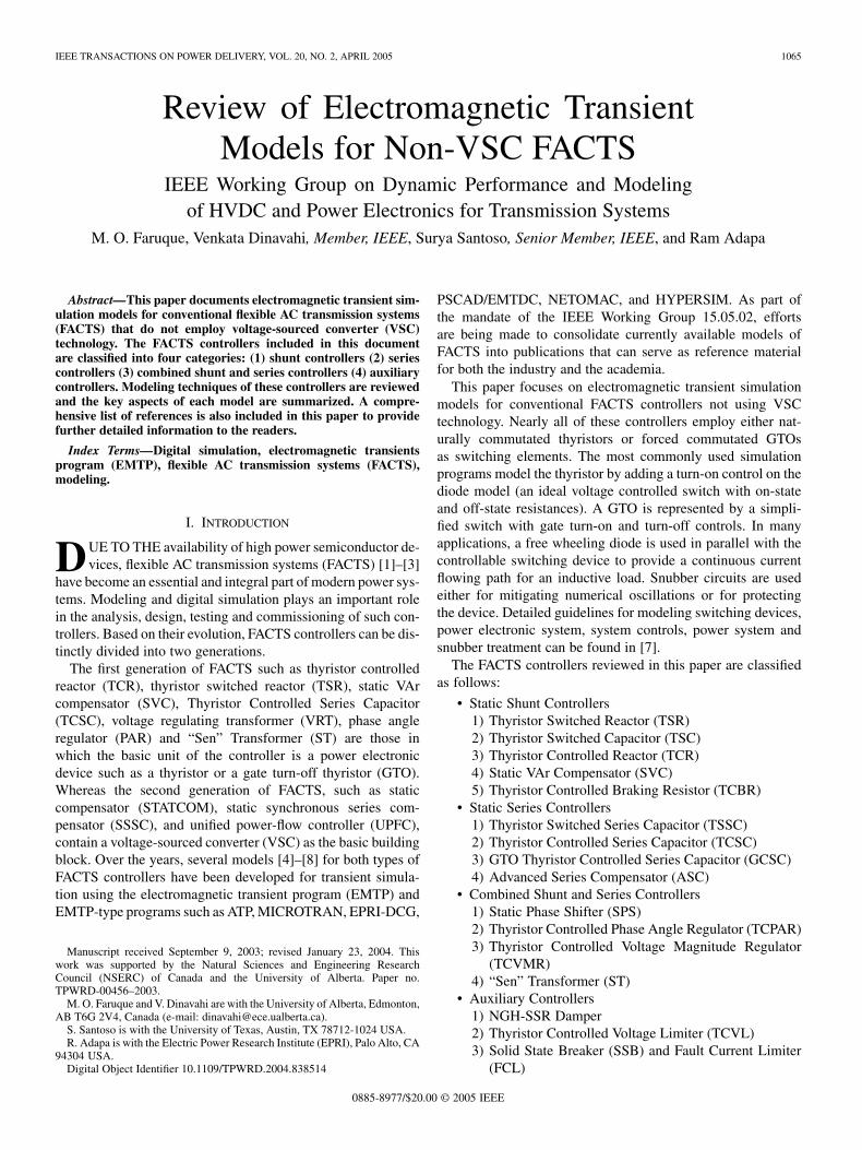
Fig. 1. Schematic diagram of (a) TSR (b) TSC.
The paper is organized as follows. For each of the above con-trollers a brief explanation of the structure, operating principleand typical application, precedes the EMTP modeling details.Section II deals with static shunt controllers. Section III ad-dresses static series controllers. Section IV deals with combinedshunt and series controllers and Section V presents the auxiliarycontrollers. Conclusions are presented in Section VI.
II. STATIC SHUNT CONTROLLERS
Shunt reactive power compensators are generally used tosupply or absorb reactive power at their point of connection.The earliest form of shunt compensation include saturablereactors (SR) and synchronous generators. The developmentof power electronics has made it possible to replace them withmodern shunt compensators such as TSR, TSC, TCR and SVC.
A. Thyristor Switched Reactor (TSR)
A TSR, shown in Fig. 1(a), is defined as a shunt connectedthyristor-switched inductor whose effective reactance is variedin a step-wise manner by full or zero conduction operation of thethyristor valve [1]. TSR is a subset of a static VAr compensator(SVC) which is made up of several shunt connected inductorsthat can be switched in and out by thyristor switches withoutany firing angle controls, providing the required step changesin the reactive power. Owing to its simple configuration and anabsence of stand-alone use (TSR appears as an integral part ofSVC in most applications), there has not been enough literaturemodeling TSR separately. However, an EMTP model of TSR, ingeneral, would include type-11 switches representing the anti-parallel thyristors working in series with an inductor.
B. Thyristor Switched Capacitor (TSC)
TSC (Fig. 1(b)) is another subset of SVC that can be definedas a shunt connected thyristor-switched capacitor whose effec-tive reactance is varied in a step-wise manner by full or zero
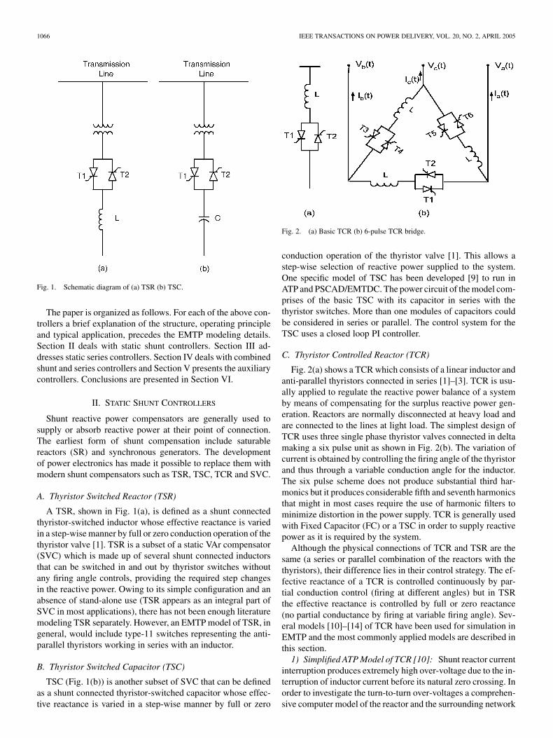
Fig. 2. (a) Basic TCR (b) 6-pulse TCR bridge.
conduction operation of the thyristor valve [1]. This allows astep-wise selection of reactive power supplied to the system.One specific model of TSC has been developed [9] to run inATP and PSCAD/EMTDC. The power circuit of the model com-prises of the basic TSC with its capacitor in series with thethyristor switches. More than one modules of capacitors couldbe considered in series or parallel. The control system for theTSC uses a closed loop PI controller.
C. Thyristor Controlled Reactor (TCR)
Fig. 2(a) shows a TCR which consists of a linear inductor andanti-parallel thyristors connected in series [1]–[3]. TCR is usu-ally applied to regulate the reactive power balance of a systemby means of compensating for the surplus reactive power gen-eration. Reactors are normally disconnected at heavy load andare connected to the lines at light load. The simplest design ofTCR uses three single phase thyristor valves connected in deltamaking a six pulse unit as shown in Fig. 2(b). The variation ofcurrent is obtained by controlling the firing angle of the thyristorand thus through a variable conduction angle for the inductor.The six pulse scheme does not produce substantial third har-monics but it produces considerable fifth and seventh harmonicsthat might in most cases require the use of harmonic filters tominimize distortion in the power supply. TCR is generally usedwith Fixed Capacitor (FC) or a TSC in order to supply reactivepower as it is required by the system.
Although the physical connections of TCR and TSR are thesame (a series or parallel combination of the reactors with thethyristors), their difference lies in their control strategy. The ef-fective reactance of a TCR is controlled continuously by par-tial conduction control (firing at different angles) but in TSRthe effective reactance is controlled by full or zero reactance(no partial conductance by firing at variable firing angle). Sev-eral models [10]–[14] of TCR have been used for simulation inEMTP and the most commonly applied models are described inthis section.
1) Simplified ATP Model of TCR [10]: Shunt reactor currentinterruption produces extremely high over-voltage due to the in-terruption of inductor current before its natural zero crossing. Inorder to investigate the turn-to-turn over-voltages a comprehen-sive computer model of the reactor and the surrounding network
FARUQUE et al.: REVIEW OF ELECTROMAGNETIC TRANSIENT MODELS FOR NON-VSC FACTS 1067
Fig. 3. (a) Simple TCR model: r = 20,R = 2M,L = 6H,C = 3nF,C = 0:6 nF, C = 2 nF, (b) detailed model of TCR.
needs to be considered. Fig. 3(a) represents the TCR modelwhere turn-to-turn stresses due to over-voltage has not been con-sidered, however, surrounding apparatus such as bus-bar capaci-tance, bushing capacitance, and resistance of the reactor are con-sidered. In its simplest form, a shunt reactor is modeled as a twoport equivalent of an inductor in parallel with a capacitor. Thelinear unsaturated inductance, and capacitance, are relatedby the equation
(1)
Where is the frequency of the free oscillation. The capacitanceis comprised of reactor capacitance , bushing capacitance
and the bus-bar capacitance
(2)
The copper losses, dielectric losses and core losses of thereactor have been represented by lumped serial/parallel resis-tances. Typical values of model parameters for a shunt reactorbank that consists of three 110 MVAr single phase units areshown in Fig. 3(a).
2) Detailed ATP Model of TCR [10]: The simplified modelfails to provide any information about the internal stresses ofthe reactor and it would not be able to predict the local over-voltages accurately. Therefore, a comprehensive EMTP modelis shown in Fig. 3(b) that is based on part inductively coupledelements. The homogeneous single-layer winding consists ofpieces of part-windings with self inductance andmutual inductances to the others. The shunt capacitors ,series capacitors and the resistors and representthe losses in part-windings. The mutual inductance between twocoupled coils is given as a function of the self inductances andthe coupling factor
(3)
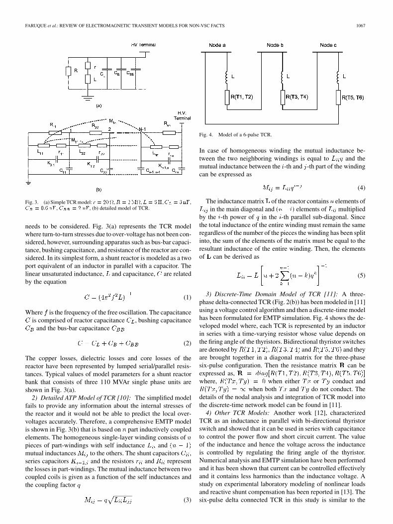
Fig. 4. Model of a 6-pulse TCR.
In case of homogeneous winding the mutual inductance be-tween the two neighboring windings is equal to and themutual inductance between the -th and -th part of the windingcan be expressed as
(4)
The inductance matrix of the reactor contains elements ofin the main diagonal and elements of multiplied
by the -th power of in the -th parallel sub-diagonal. Sincethe total inductance of the entire winding must remain the sameregardless of the number of the pieces the winding has been splitinto, the sum of the elements of the matrix must be equal to theresultant inductance of the entire winding. Then, the elementsof can be derived as
(5)
3) Discrete-Time Domain Model of TCR [11]: A three-phase delta-connected TCR (Fig. 2(b)) has been modeled in [11]using a voltage control algorithm and then a discrete-time modelhas been formulated for EMTP simulation. Fig. 4 shows the de-veloped model where, each TCR is represented by an inductorin series with a time-varying resistor whose value depends onthe firing angle of the thyristors. Bidirectional thyristor switchesare denoted by , and and theyare brought together in a diagonal matrix for the three-phasesix-pulse configuration. Then the resistance matrix can beexpressed as,where, when either or conduct and
when both and do not conduct. Thedetails of the nodal analysis and integration of TCR model intothe discrete-time network model can be found in [11].
4) Other TCR Models: Another work [12], characterizedTCR as an inductance in parallel with bi-directional thyristorswitch and showed that it can be used in series with capacitanceto control the power flow and short circuit current. The valueof the inductance and hence the voltage across the inductanceis controlled by regulating the firing angle of the thyristor.Numerical analysis and EMTP simulation have been performedand it has been shown that current can be controlled effectivelyand it contains less harmonics than the inductance voltage. Astudy on experimental laboratory modeling of nonlinear loadsand reactive shunt compensation has been reported in [13]. Thesix-pulse delta connected TCR in this study is similar to the
1068 IEEE TRANSACTIONS ON POWER DELIVERY, VOL. 20, NO. 2, APRIL 2005
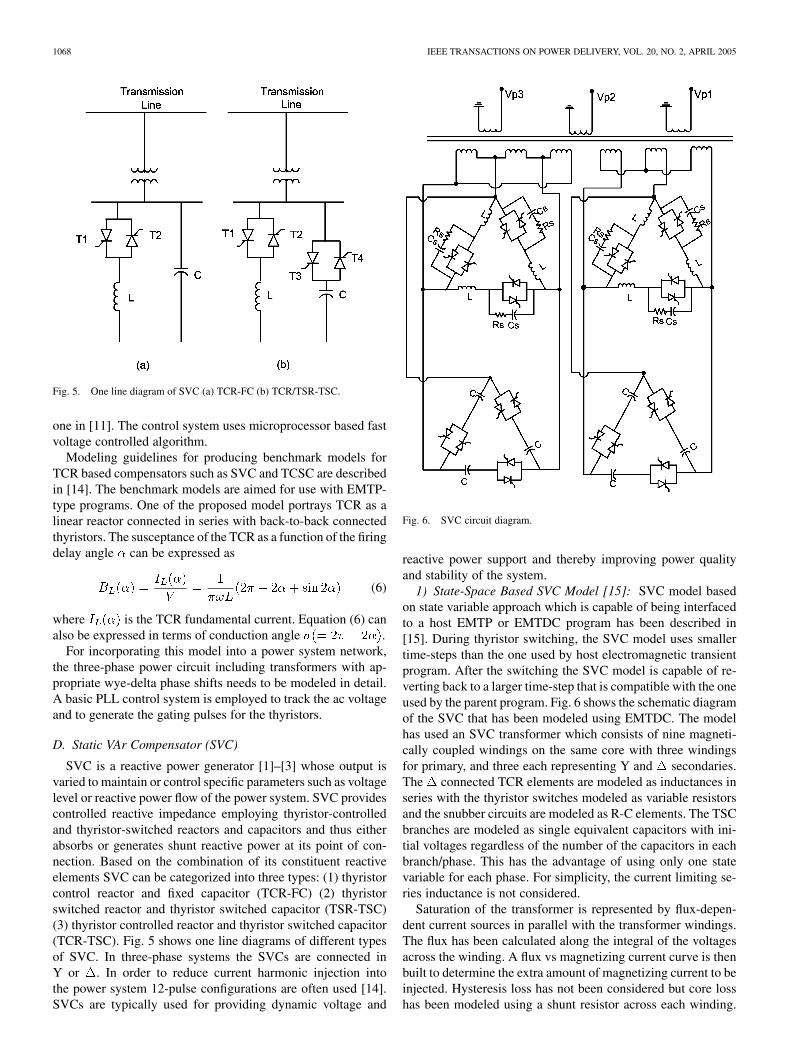
Fig. 5. One line diagram of SVC (a) TCR-FC (b) TCR/TSR-TSC.
one in [11]. The control system uses microprocessor based fastvoltage controlled algorithm.
Modeling guidelines for producing benchmark models forTCR based compensators such as SVC and TCSC are describedin [14]. The benchmark models are aimed for use with EMTP-type programs. One of the proposed model portrays TCR as alinear reactor connected in series with back-to-back connectedthyristors. The susceptance of the TCR as a function of the firingdelay angle can be expressed as
(6)
where is the TCR fundamental current. Equation (6) canalso be expressed in terms of conduction angle .
For incorporating this model into a power system network,the three-phase power circuit including transformers with ap-propriate wye-delta phase shifts needs to be modeled in detail.A basic PLL control system is employed to track the ac voltageand to generate the gating pulses for the thyristors.
D. Static VAr Compensator (SVC)
SVC is a reactive power generator [1]–[3] whose output isvaried to maintain or control specific parameters such as voltagelevel or reactive power flow of the power system. SVC providescontrolled reactive impedance employing thyristor-controlledand thyristor-switched reactors and capacitors and thus eitherabsorbs or generates shunt reactive power at its point of con-nection. Based on the combination of its constituent reactiveelements SVC can be categorized into three types: (1) thyristorcontrol reactor and fixed capacitor (TCR-FC) (2) thyristorswitched reactor and thyristor switched capacitor (TSR-TSC)(3) thyristor controlled reactor and thyristor switched capacitor(TCR-TSC). Fig. 5 shows one line diagrams of different typesof SVC. In three-phase systems the SVCs are connected inY or . In order to reduce current harmonic injection intothe power system 12-pulse configurations are often used [14].SVCs are typically used for providing dynamic voltage and
Fig. 6. SVC circuit diagram.
reactive power support and thereby improving power qualityand stability of the system.
1) State-Space Based SVC Model [15]: SVC model basedon state variable approach which is capable of being interfacedto a host EMTP or EMTDC program has been described in[15]. During thyristor switching, the SVC model uses smallertime-steps than the one used by host electromagnetic transientprogram. After the switching the SVC model is capable of re-verting back to a larger time-step that is compatible with the oneused by the parent program. Fig. 6 shows the schematic diagramof the SVC that has been modeled using EMTDC. The modelhas used an SVC transformer which consists of nine magneti-cally coupled windings on the same core with three windingsfor primary, and three each representing Y and secondaries.The connected TCR elements are modeled as inductances inseries with the thyristor switches modeled as variable resistorsand the snubber circuits are modeled as R-C elements. The TSCbranches are modeled as single equivalent capacitors with ini-tial voltages regardless of the number of the capacitors in eachbranch/phase. This has the advantage of using only one statevariable for each phase. For simplicity, the current limiting se-ries inductance is not considered.
Saturation of the transformer is represented by flux-depen-dent current sources in parallel with the transformer windings.The flux has been calculated along the integral of the voltagesacross the winding. A flux vs magnetizing current curve is thenbuilt to determine the extra amount of magnetizing current to beinjected. Hysteresis loss has not been considered but core losshas been modeled using a shunt resistor across each winding.
FARUQUE et al.: REVIEW OF ELECTROMAGNETIC TRANSIENT MODELS FOR NON-VSC FACTS 1069
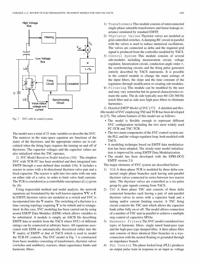
Fig. 7. SVC with its control system.
The model uses a total of 21 state variables to describe the SVC.The matrices in the state-space equation are functions of thestates of the thyristors, and the appropriate entries are re-cal-culated when the firing logic requires the turning on and off ofthyristors. The capacitor voltages and the capacitor values arealso initialized when the TSC operates.
2) SVC Model Based on Nodal Analysis [16]: The simplestSVC with TCR-FC has been modeled and then integrated intoEMTP through a user-defined data module [16]. It includes areactor in series with a bi-directional thyristor-valve pair and afixed capacitor. The reactor is split into two units with one uniton either side of a valve, in order to limit valve fault currents.The TCR is considered as a controllable susceptance givenby (6).
Using trapezoidal method and nodal analysis, the networkequations are formulated by the well known equation .In EMTP, thyristor valves are modeled as a switch and SVC isincorporated into the matrix. The switching of a thyristor is atime-varying topology requiring to be rebuilt and re-triangu-lated. In this case, SVC modeling has been carried out by usingnested EMTP Data Modules (EDM) which allows variables tobe substituted. A module is simply an ASCII file describingEMTP data or models from the TACS where SVCs of differentratings can be connected at arbitrary buses. All equations asso-ciated with EDM are automatically discretized either into the
matrix of EMTP or that of TACS which is used to modelthe TCR-FC controls. The SVC model in Fig. 7 is constructedfrom basic modules consisting of transformers, thyristor valves(switches and snubbers), reactors, shunt capacitance banks andharmonic filters.
1) Transformers This module consists of interconnectedsingle-phase saturable transformers and linear leakage re-actance simulated by standard EMTP.
2) Thyristor Valves Thyristor valves are modeled asgrid controlled switches. A damping RC circuit in parallelwith the valves is used to reduce numerical oscillations.The valves are connected as delta and the required gridsignal is produced from the controller modeled by TACS.
3) Control System This module consists of severalsub-modules including measurement circuit, voltageregulator, linearization circuit, conduction angle order ,the synchronizing circuits and the firing pulse generatorentirely described by TACS statements. It is possiblein the control module to change the main settings ofthe input filters, the slope and the time constant of theregulators through modification or creating sub-modules.
4) Filtering This module can be modified by the userand may vary somewhat but its general characteristics re-main the same. The dc side typically uses 60-120-360 Hznotch filter and ac side uses high-pass filters to eliminateharmonics.
3) Detailed EMTP Model of SVC [17]: A detailed and flex-ible model of SVC employing TSCand TCR has been developedin [17]. The salient features of this model are as follows:
• The model is flexible enough to represent differentSVC configuration including the two most widely usedFC-TCR and TSC-TCR.
• The two main components of the SVC control system are:the PLL and the voltage regulator loop, both modeled withTACS.
• A modeling technique based on EMTP data modulariza-tion has been adopted. The steady-state model initializa-tion is improved by using EMTP Data Modularization.
• The model has been developed with the EPRI-DCGEMTP version 2.0.
The major elements of SVC system are described below:
1) TCR A three-phase TCR is modeled by three delta-con-nected single phase branches each having anti-parallelthyristor valves connected in series between two reactorunits. The thyristor valves are controlled as a six-pulsegroup by gate signals coming from TACS.
2) TSC A three phase TSC unit consists of three deltaconnected branches each having a pair of anti-parallelthyristor valves in series with a capacitor bank and atuning and/or current limiting reactor. A TSC firingcircuit controls the TSC unit which allows the capacitorbank either fully on or off. The model allows connectionof a number of TSC unit in parallel to achieve a multiplestep control of capacitive MVAr.
3) Harmonic Filters The SVC model considered twotypes of harmonic filters: single tuned band-pass typeand the high-pass type damped filter. A three phase filterunit consists of three identical filter branches in a wye-connection with the neutral floating or grounded throughan impedance branch.
4) PLL Control The phase locked loop (PLL) producesan output pulse train in response to an input ac voltage
1070 IEEE TRANSACTIONS ON POWER DELIVERY, VOL. 20, NO. 2, APRIL 2005
signal, reducing the phase error between the signals bynegative feedback control. The phase locked loop con-sists of four functional blocks: a phase comparator, a PIregulator, a voltage controlled oscillator and a frequencydivider. The output signal of the phase locked loop isused as the reference for the firing angles of the TCRand TSC.
5) Voltage Regulator The voltage regulator per-forms the closed loop voltage control. The differencebetween the voltage reference and the network voltageresponse is fed as the control error signal to a PI regu-lator which changes the total SVC susceptance with theaid of higher level control blocks.
6) Allocator The allocator converts the susceptance ref-erence signal obtained from the voltage regulator to log-ical orders (On/Off) for the TSCs and arithmetic ordersfor the TCRs. The output of the module contains twoquantities: The number of TSC unit required to be in thecircuit and the susceptance order for the TCR.
7) Linearizer The linearizer converts the susceptanceorder from the allocator to a firing angle order whichis measured from the time of the last voltage peak.
8) TCR Firing CircuitThe TCR firing circuit gener-ates firing pulses to the three-phase TCR unit. The syn-chronizing signal from the PLL circuit and the firing an-gles determined by the linearizer are the inputs to theTCR firing circuit. The pulse is directed to one of theanti-parallel thyristor valves.
9) TSC Firing Circuit The TSC firing circuit gener-ates firing pulses to the three-phase TSC unit. Each TSCunit is assigned a priority number by the user and they areturned on sequentially from the lowest priority number tothe highest.
10) Measurement Circuit The purpose of measure-ment circuit is to provide the voltage regulator with thepower system voltage response. The model allows dif-ferent techniques for the representation of the measure-ment circuit.
In addition to the above elements, some typical SVC controlfunctions such as TCR over-current control, secondary over-voltage limiter, under-voltage strategy are also included in themodel. Further details can be found in [17]. A similar detailedEMTP-TACS model of an actual SVC was presented in [18] andthe transient simulations were verified using TNA studies. Maincomponents of the SVC such as power circuit, control system,measuring circuits and voltage regulators, synchronizing andfiring circuits, current limiter are discussed comprehensively. Inaddition, the Under-voltage Blocking Scheme (UBS) and theBOD Blocking Scheme (BBS) are the two special features de-scribed in this work.
4) SVC Model Using EMTP Data Modularization [19]: Adigitally controlled SVC used for optimal load compensationhas been studied in [19] using ATP. The major units of the SVCare the power circuit that consists of TCR and FC unit andthe control system. The power circuit is formed by three delta-connected single-phase branches each one having anti-parallelthyristors in series with a reactor unit and three delta connectedfixed capacitors. Surrounding power system components such
as the sources, lines, switches and the digital controller are mod-eled using EMTP Data Modularization technique described in[20]. Details of these rules can be found in [21]–[23].
5) Detailed Model of SVC Using PSCAD/EMTDC [24]:Transient performance of SVC has been studied using PSCAD[24] mainly during faults, switching, load rejection and en-ergizing of transformers and shunt reactors. The SVC modelincluding its control system has the following main components.
1) TCR and Phase Control The TCR reactor isconsidered as a continuously variable reactor and deltaconnected with each leg comprising air cored inductorsin series with anti-parallel line commutated thyristors. ATCR controller is implemented as standard model blockin PSCAD/EMTDC and for each independent phaseconsists of a phase locked oscillator, firing latch and atriggering pulse generator.
2) TSC and Harmonic Filters The SVC modelincludes shunt capacitor banks which allow it to supplyreactive power to the supply system and provide voltagesupport. Dynamically controlled capacitive support issupplied by TSCs and adjusted by control of relativelysmaller TCR. Each TSC comprises delta connectedlegs with a capacitor bank and air-cored inrush-limitinginductor in series with anti-parallel line commutatedthyristors. An iron-cored transformer together with resis-tors in each phase are used to reduce the voltage stresson the thyristors after turn-off. Surge arrestors acrossthe thyristor valves are used to protect against excessivetransient voltages. Two filter banks tuned at 5th and 7thharmonics frequencies are used to absorb the dominantharmonics produced by the TCR.
3) Other SVC Equipment The SVC step-down trans-former model in PSCAD includes representation of itsleakage reactance and magnetizing current which is de-pendent on the level of magnetic saturation in its ironcore. For fast transient analysis stray capacitances be-tween windings and to earth is also considered. The SVCbus-bar is represented by distributed transmission lines.
4) Other SVC Control Systems Other than themain SVC control, a supplementary control loop is intro-duced to allow co-ordination with other reactive powersources.
6) Other SVC Models: A model similar to [17] for dig-ital simulation of SVC using TCR-FC has been presented in[25]. The method describes simultaneous digital simulation ofthyristors, their Gate Pulse Generating (GPG) circuit and theinterface with the power system. The model consists of digitalrepresentations for the individual components found in thecircuit, the logic elements in the GPG which is simulated usingTACS. Linear elements such as TCR reactors are representedby lumped parameters. The coupling transformer is modeledas interconnected single-phase saturable transformers andlinear reactors. Thyristor valves are modeled as grid controlledswitches using TACS. Snubbers are used to prevent numericaloscillations.
A simple model of SVC (power circuit and control) is dis-cussed in [14]. In that model, TCR is paired with either a set of
FARUQUE et al.: REVIEW OF ELECTROMAGNETIC TRANSIENT MODELS FOR NON-VSC FACTS 1071
Fig. 8. Schematic diagram of TCBR.
TSR or TCR and TSC modules. Multiple levels of control areemployed and synchronization of TCR firing is done with re-spect to phase voltage. Protection circuits for over-current in thethyristors and over-voltage on the capacitors are also included.
A comparative analysis of the field tests and digital simu-lations using EMTP-TACS for the commissioning of a
MVAr SVC in Brazil has been reported in [26]. The SVCconsisted of TSC (60 MVAr), TCR (60 MVAr) and a fifth har-monic filter (10 MVAr). These units were connected to a 230 kVbus bar system.
E. Thyristor Controlled Braking Resistor (TCBR)
As shown in Fig. 8, TCBR is a shunt connected thyristorswitched resistor which is controlled to aid stabilization of apower system or to minimize power acceleration of a generatingunit during a disturbance [1]. It is used to damp low frequencyoscillations with or without firing control. It involves switchingof a resistor (usually linear) by a thyristor based ac switch. TheEMTP model of TCBR would mainly consists of anti-parallelswitches connected in series with a resistor. The application ofa dynamic brake at the generator terminal has been studied in[27]. Two types of dynamic brake configuration have been con-sidered: a three-phase, bi-directional, full-wave, Y-connectedphase-controlled ac/ac converter and a three-phase, full-wave,thyristor-controlled rectifier bridge. A simple rule-based on-offcontrol law based on the local measurements of generator outputpower and its derivative is proposed. The model and its controlsystem has been validated through detailed digital simulationstudies using PSCAD/EMTDC.
III. STATIC SERIES CONTROLLERS
Series controllers [1] are employed in transmission lines inorder to control the overall reactive voltage drop across the lineand hence to control the transmitted electric power. A seriescontroller could simply be a variable impedance such as capaci-tive reactance or a quadrature voltage injection obtained using aVSC with or without the aid of an external energy source. Exam-ples of the former category of series controllers include TSSC,TCSC, GTO-CSC and ASC.
Fig. 9. Schematic diagram of TSSC/TCSC.
A. Thyristor Switched Series Capacitor (TSSC)
TSSC is a capacitive reactance compensator which consistsof a series capacitor bank shunted by a thyristor-switched re-actor to provide a step-wise control of series capacitive reac-tance [1]–[3]. By switching the anti-parallel thyristors the ca-pacitor can be placed in and out of the transmission line. Owingto its simple configuration a TSSC can be modeled in EMTPusing lumped Cs, Ls and thyristor switches. Such a basic modelfor TSSC has been developed in [9] and implemented usingATP. Fig. 9 shows the schematic diagram of a TSSC and TCSCwhich are same in terms of physical connection but different inoperation and control.
B. Thyristor Controlled Series Capacitor (TCSC)
TCSC is defined [1] as a capacitive reactance compensatorwhich consists of a series capacitor bank shunted by a thyristorcontrolled reactor in order to provide a smoothly variable seriescapacitive reactance. TCSC normally employs line-commutatedthyristors but self-commutated GTOs are also used. A TCR isconnected across the capacitor to provide variable reactance.When the TCR firing angle is 180 the reactor does not conductand the impedance is capacitive, but for a firing angle of 90 thereactor is in full conduction and the total impedance is inductive.TCSC can be a single large unit or may consists of several smallunits connected in parallel to yield better control.
Most of the TCSCs applied in power systems work in threedifferent modes: Thyristor Switched Reactor (TSR) mode,Waiting Mode (WTM) and Thyristor Blocked Mode (TBM).In TSR mode the thyristors conduct fully effectively bypassingthe capacitor bank through the TCR, and the TCSC impedancechanges from a capacitive to an inductive value. This modeprovides the means of limiting the line current through theincrease of line impedance. In WTM, the TCSC waits for acertain time with a fixed firing angle until another mode ofoperation is set. In TBM, the control firing signals are blockedand the TCSC becomes a series capacitor.
1) Simplified TCSC Model [28]: Fig. 10 illustrates a sim-plified TCSC model developed using EMTP and MODELS forsimulating SSR in a 500 kV network of the N-W AmericanPower System with installed series compensation. The TCSCis modeled by a capacitor, in parallel with anti-parallel thyristorswitches and commutation inductor. The TCSC is also equippedwith a bypass circuit breaker. Multi-mass model has been usedfor the mechanical system for studying SSR. Transmission linesare modeled using distributed parameters.
1072 IEEE TRANSACTIONS ON POWER DELIVERY, VOL. 20, NO. 2, APRIL 2005
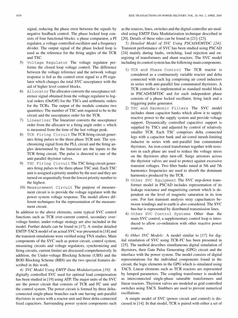
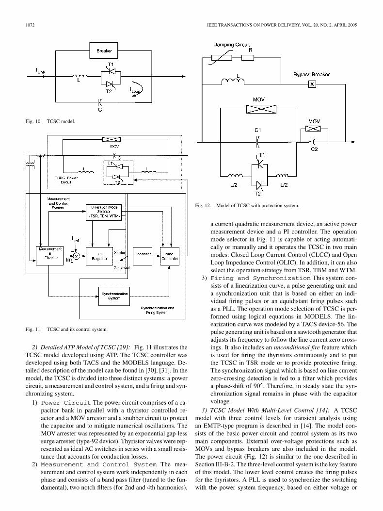
Fig. 10. TCSC model.
Fig. 11. TCSC and its control system.
2) Detailed ATP Model of TCSC [29]: Fig. 11 illustrates theTCSC model developed using ATP. The TCSC controller wasdeveloped using both TACS and the MODELS language. De-tailed description of the model can be found in [30], [31]. In themodel, the TCSC is divided into three distinct systems: a powercircuit, a measurement and control system, and a firing and syn-chronizing system.
1) Power Circuit The power circuit comprises of a ca-pacitor bank in parallel with a thyristor controlled re-actor and a MOV arrestor and a snubber circuit to protectthe capacitor and to mitigate numerical oscillations. TheMOV arrester was represented by an exponential gap-lesssurge arrester (type-92 device). Thyristor valves were rep-resented as ideal AC switches in series with a small resis-tance that accounts for conduction losses.
2) Measurement and Control System The mea-surement and control system work independently in eachphase and consists of a band pass filter (tuned to the fun-damental), two notch filters (for 2nd and 4th harmonics),
Fig. 12. Model of TCSC with protection system.
a current quadratic measurement device, an active powermeasurement device and a PI controller. The operationmode selector in Fig. 11 is capable of acting automati-cally or manually and it operates the TCSC in two mainmodes: Closed Loop Current Control (CLCC) and OpenLoop Impedance Control (OLIC). In addition, it can alsoselect the operation strategy from TSR, TBM and WTM.
3) Firing and Synchronization This system con-sists of a linearization curve, a pulse generating unit anda synchronization unit that is based on either an indi-vidual firing pulses or an equidistant firing pulses suchas a PLL. The operation mode selection of TCSC is per-formed using logical equations in MODELS. The lin-earization curve was modeled by a TACS device-56. Thepulse generating unit is based on a sawtooth generator thatadjusts its frequency to follow the line current zero cross-ings. It also includes an unconditional fire feature whichis used for firing the thyristors continuously and to putthe TCSC in TSR mode or to provide protective firing.The synchronization signal which is based on line currentzero-crossing detection is fed to a filter which providesa phase-shift of 90 . Therefore, in steady state the syn-chronization signal remains in phase with the capacitorvoltage.
3) TCSC Model With Multi-Level Control [14]: A TCSCmodel with three control levels for transient analysis usingan EMTP-type program is described in [14]. The model con-sists of the basic power circuit and control system as its twomain components. External over-voltage protections such asMOVs and bypass breakers are also included in the model.The power circuit (Fig. 12) is similar to the one described inSection III-B-2. The three-level control system is the key featureof this model. The lower level control creates the firing pulsesfor the thyristors. A PLL is used to synchronize the switchingwith the power system frequency, based on either voltage or
FARUQUE et al.: REVIEW OF ELECTROMAGNETIC TRANSIENT MODELS FOR NON-VSC FACTS 1073
current measurements. The lower level control also generatesthe gate pulses with the required phase delay as commandedby the intermediate level controller. One source of concernin obtaining an accurate model is the impact of the time-stepdiscretization on the gate pulses. Some EMTP-type programsare capable of adjusting this through interpolation duringswitching and then using larger time-steps for the remainderof the simulation. Others use smaller time-steps throughoutto avoid difficulties with switching between time-steps. Theintermediate level controller provides the control objective forthe converter. For example, the TCSC could be controlled toinsert a specific reactance or voltage in the line, or to providedamping of SSR. The control quantities would then be usedto produce the necessary firing delay angle. The outer controllevel represents the converter protection functions.
4) Analytical Models of TCSC [32]–[38]: Most of theanalytical models in the literature aim to predict the behaviorof TCSC and its interaction with the power system usingdifferential equations. However, nonlinear phenomena suchas thyristor switchings and passive damping make it difficultto model the system accurately. Linearization is then adoptedto express the system equations in a form amenable to digitalsimulation. Simulation results are then validated by usingEMTP-type programs. The analytical models have been mainlyused to study SSR phenomenon.
Details of TCSC dynamics for three operating modes basedon state-space analysis are reported in [32]. Transient char-acteristics as well as steady-state characteristics of the TCSCare studied using a system of one machine connected to aninfinite bus through a thyristor controlled series compensatedtransmission line. The switching of the thyristor is linearizedusing a switching function [33]. The TCSC transmission systemis modeled using nonhomogeneous differential equations withperiodic coefficients. State-space techniques are then used tosolve the analytical equations. Simulations are performed usingMATLAB and then validated using EMTP.
An accurate analytical model of the TCSC which is validin the frequency range from 0 Hz to twice the operating fre-quency is presented in [34]. The objective of the study wasto develop a continuous-time model of the main circuit of theTCSC which accounts for the effects of thyristor switchingson capacitor voltage. The model incorporates the thyristor trig-gering logic, the synchronization system and higher level con-trol loops such as power oscillation damping loop. The inputsto the model are the capacitor voltage, componentsof line current and the triggering time. The output of the modelis the capacitor voltage after one half cycle. This model is suit-able for linearized analysis of a power system using frequencydomain methods.
A linear TCSC dynamic model is obtained by linearizingthe half-period map associated with sampling the TCSC capac-itor voltage twice every cycle in [35]. It also includes passivedamping which varies with steady-state conduction angle of theTCSC. Dynamic phasor models [36], [37] have also been usedto study SSR in a TCSC compensated transmission line. Thesemodels are an alternative to sampled-data models and are basedon the representation of voltages and currents as time-varyingFourier series. A comparison based on digital simulation be-
tween the quasistatic model and dynamic model of TCSC canbe found in [38].
5) Other TCSC Models: Digital simulation of a TCSCbased EHV transmission system has been performed in [39]where a method for simultaneous modeling of thyristors,their control, firing circuits and protection equipment usingEMTP-TACS has been described. The power circuit for theseries compensation study includes TCR, fixed and controllablecapacitors, and other typical components such as generators,transmission lines, transformers, and breakers. The paperstudies a 500 kV system under both normal and faulted con-ditions. Tools for modeling TCSC along with other FACTScontrollers in large ac systems are reported in [40]. Modelingand interfacing techniques for combined transient/dynamicanalysis of HVDC and FACTS systems are described in [41].In this study EPRI-DCG EMTP is interfaced with a TransientStability Program (TSP) to simulate both HVDC and TCSCbased systems.
The application of TCSC as a fault current limiter in distri-bution systems is investigated using EMTP in [42]. A linearizeddiscrete-time model of a thyristor controlled series compensatedtransmission line is presented in [43] where a TCR is used asthe compensating device. The discretization is performed at thepeaks of the capacitor voltage of the series compensator. Dig-ital simulation is used to validate the robustness of a closed-loopcontroller designed using this model. Several other modelingand simulation studies of TCSC [44]–[55] have been found inthe literature. Most of these studies either simulate or validateTCSC models using EMTP.
C. GTO Controlled Series Capacitor (GTO-CSC)
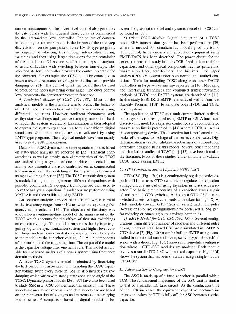
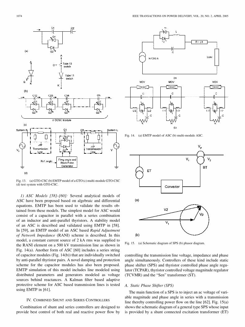
GTO-CSC (Fig. 13(a)) is a continuously regulated series ca-pacitor [1] that uses GTO switches to regulate the capacitorvoltage directly instead of using thyristors in series with a re-actor. The basic circuit consists of a capacitor across a pairof anti-parallel GTO switches. Although a GTO-CSC can beswitched at zero voltage, care needs to be taken for high .Multi-module (several GTO-CSCs in series) and multi-pulse(6-pulse or 12-pulse) configurations have been used in [56], [57]for reducing or canceling output voltage harmonics.
1) EMTP Model for GTO-CSC [56], [57]: Several config-urations using different number of modules and different pulsearrangements of GTO based CSC were simulated in EMTP. AGTO device [7] (Fig. 13(b)) can be built in EMTP using a con-trolled bi-directional current flowing switch (type-13 switch) inseries with a diode. Fig. 13(c) shows multi-module configura-tion where GTO-CSC modules are modeled. Each moduleinvolves a small GTO-CSC with a fixed capacitor. Fig. 13(d)shows the system that has been simulated using a single moduleGTO-CSC.
D. Advanced Series Compensator (ASC)
The ASC is made up of a fixed capacitor in parallel with aTCR. The fundamental impedance of the ASC unit is similarto that of a parallel LC tank circuit. As the conduction timeof the TCR increases, the equivalent capacitive reactance in-creases and when the TCR is fully off, the ASC becomes a seriescapacitor.
1074 IEEE TRANSACTIONS ON POWER DELIVERY, VOL. 20, NO. 2, APRIL 2005
Fig. 13. (a) GTO-CSC (b) EMTP model of a GTO (c) multi-module GTO-CSC(d) test system with GTO-CSC.
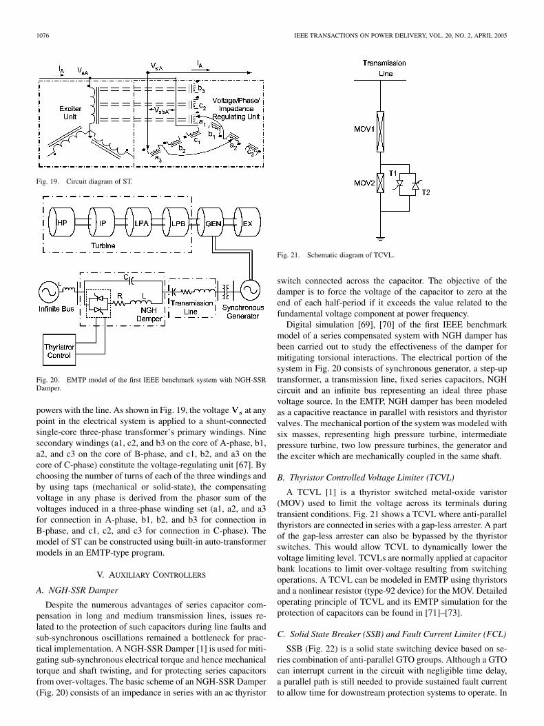
1) ASC Models [58]–[60]: Several analytical models ofASC have been proposed based on algebraic and differentialequations. EMTP has been used to validate the results ob-tained from these models. The simplest model for ASC wouldconsist of a capacitor in parallel with a series combinationof an inductor and anti-parallel thyristors. A stability modelof an ASC is described and validated using EMTP in [58].In [59], an EMTP model of an ASC based Rapid Adjustmentof Network Impedance (RANI) scheme is described. In thismodel, a constant current source of 2 kA rms was supplied tothe RANI element on a 500 kV transmission line as shown inFig. 14(a). Another form of ASC [60] includes a series stringof capacitor modules (Fig. 14(b)) that are individually switchedby anti-parallel thyristor pairs. A novel damping and protectionscheme for the capacitor modules has also been proposed.EMTP simulation of this model includes line modeled usingdistributed parameters and generators modeled as voltagesources behind reactances. A Kalman filter based adaptiveprotective scheme for ASC based transmission lines is testedusing EMTP in [61].
IV. COMBINED SHUNT AND SERIES CONTROLLERS
Combination of shunt and series controllers are designed toprovide best control of both real and reactive power flow by
Fig. 14. (a) EMTP model of ASC (b) multi-module ASC.
Fig. 15. (a) Schematic diagram of SPS (b) phasor diagram.
controlling the transmission line voltage, impedance and phaseangle simultaneously. Controllers of these kind include staticphase shifter (SPS) and thyristor controlled phase angle regu-lator (TCPAR), thyristor controlled voltage magnitude regulator(TCVMR) and the “Sen” transformer (ST).
A. Static Phase Shifter (SPS)
The main function of a SPS is to inject an ac voltage of vari-able magnitude and phase angle in series with a transmissionline thereby controlling power flow on the line [62]. Fig. 15(a)shows the schematic diagram of a general type SPS whose inputis provided by a shunt connected excitation transformer (ET)
FARUQUE et al.: REVIEW OF ELECTROMAGNETIC TRANSIENT MODELS FOR NON-VSC FACTS 1075
Fig. 16. TCPAR circuit.
and whose output voltage is injected in the system by the se-ries booster transformer (BT). The converter controls the mag-nitude and/or phase angle of the injected voltage . Typicalapplication of SPS include: (1) improving transient stability, (2)damping inter-area oscillation, (3) mitigating SSR and (4) con-trolling loop power flow.
Depending on the construction and circuit arrangements, SPShas been classified into several categories. A comprehensivereview of the various categories can be found in [63], [64].Of these schemes some use thyristor based converters whileothers employ VSCs with the capability of injecting real or re-active power as well as controlling the frequency of the injectedvoltage. The VSC based SPSs are beyond the scope of this paper.A typical thyristor based phase angle regulator and its EMTPmodel is described in the next section.
B. Thyristor Controlled Phase Angle Regulator (TCPAR)
Phase shifting in TCPAR is achieved by adding a quadraturevoltage vector in series with a phase. The voltage vector is de-rived from the other two phases via a shunt connected trans-former and it is made variable with the help of various thyristortopologies. Thus, a controllable voltage injection is obtainedwhere the phase-angle between the voltages at the two endscan be varied in the range of , withoutchanging the magnitude of the injected voltage [1], [2]. TCPARis also referred to as Thyristor Controlled Phase Shifting Trans-former (TCPST).
1) EMTP Model for TCPAR [65]: Fig. 16 shows the cir-cuit topology for a quasi bi-directional single core transformerTCPAR, that has the capability for a multi-step 0 to 30 or 0 to
phase-angle regulation. Fig. 17 shows the one-line rep-resentation of the EMTP model. All the anti-parallel thyristors( to ) are modeled as ideal switches and their closing andopening is specified at zero current. The transmission lines atthe two ends are represented as lumped T models consisting ofseries impedances and and shunt admittances . and
represent the impedance of two windings of the transformer.
Fig. 17. EMTP model of TCPAR.
Fig. 18. (a) TCVMR based on tap changer (b) TCVMR based on voltageinjection.
C. Thyristor Controlled Voltage Magnitude Regulator(TCVMR)
A TCVMR is either a regular transformer with thyristorcontrolled tap changer or with a thyristor controlled ac to acvoltage converter for injection of variable ac voltage of thesame phase in series with the line [1]. Fig. 18(a) shows a singlephase TCVMR based on tap changer. Fig. 18(b) shows anotherkind of TCVMR that is based on voltage injection in the samephase. EMTP model of a TCVMR includes a transformer withon-line tap changer (OLTC). A change in tap setting can bemodeled as a change in the turns-ratio of the transformer. Theper-unit leakage reactance and magnetizing currents, specifiedfor 100% tap, are used to calculate admittances for the newvoltage rating, corresponding to the selected tap setting by thethyristor switches [66].
D. “Sen” Transformer (ST)
The ST is mainly an autotransformer which connects acompensating voltage of line frequency but variable magnitudeand phase angle in series with the transmission line, in orderto regulate voltage magnitude, phase angle, impedance or anycombination of them on the transmission system [67], [68].The compensating voltage exchanges both real and reactive
1076 IEEE TRANSACTIONS ON POWER DELIVERY, VOL. 20, NO. 2, APRIL 2005
Fig. 19. Circuit diagram of ST.
Fig. 20. EMTP model of the first IEEE benchmark system with NGH-SSRDamper.
powers with the line. As shown in Fig. 19, the voltage at anypoint in the electrical system is applied to a shunt-connectedsingle-core three-phase transformer’s primary windings. Ninesecondary windings (a1, c2, and b3 on the core of A-phase, b1,a2, and c3 on the core of B-phase, and c1, b2, and a3 on thecore of C-phase) constitute the voltage-regulating unit [67]. Bychoosing the number of turns of each of the three windings andby using taps (mechanical or solid-state), the compensatingvoltage in any phase is derived from the phasor sum of thevoltages induced in a three-phase winding set (a1, a2, and a3for connection in A-phase, b1, b2, and b3 for connection inB-phase, and c1, c2, and c3 for connection in C-phase). Themodel of ST can be constructed using built-in auto-transformermodels in an EMTP-type program.
V. AUXILIARY CONTROLLERS
A. NGH-SSR Damper
Despite the numerous advantages of series capacitor com-pensation in long and medium transmission lines, issues re-lated to the protection of such capacitors during line faults andsub-synchronous oscillations remained a bottleneck for prac-tical implementation. A NGH-SSR Damper [1] is used for miti-gating sub-synchronous electrical torque and hence mechanicaltorque and shaft twisting, and for protecting series capacitorsfrom over-voltages. The basic scheme of an NGH-SSR Damper(Fig. 20) consists of an impedance in series with an ac thyristor
Fig. 21. Schematic diagram of TCVL.
switch connected across the capacitor. The objective of thedamper is to force the voltage of the capacitor to zero at theend of each half-period if it exceeds the value related to thefundamental voltage component at power frequency.
Digital simulation [69], [70] of the first IEEE benchmarkmodel of a series compensated system with NGH damper hasbeen carried out to study the effectiveness of the damper formitigating torsional interactions. The electrical portion of thesystem in Fig. 20 consists of synchronous generator, a step-uptransformer, a transmission line, fixed series capacitors, NGHcircuit and an infinite bus representing an ideal three phasevoltage source. In the EMTP, NGH damper has been modeledas a capacitive reactance in parallel with resistors and thyristorvalves. The mechanical portion of the system was modeled withsix masses, representing high pressure turbine, intermediatepressure turbine, two low pressure turbines, the generator andthe exciter which are mechanically coupled in the same shaft.
B. Thyristor Controlled Voltage Limiter (TCVL)
A TCVL [1] is a thyristor switched metal-oxide varistor(MOV) used to limit the voltage across its terminals duringtransient conditions. Fig. 21 shows a TCVL where anti-parallelthyristors are connected in series with a gap-less arrester. A partof the gap-less arrester can also be bypassed by the thyristorswitches. This would allow TCVL to dynamically lower thevoltage limiting level. TCVLs are normally applied at capacitorbank locations to limit over-voltage resulting from switchingoperations. A TCVL can be modeled in EMTP using thyristorsand a nonlinear resistor (type-92 device) for the MOV. Detailedoperating principle of TCVL and its EMTP simulation for theprotection of capacitors can be found in [71]–[73].
C. Solid State Breaker (SSB) and Fault Current Limiter (FCL)
SSB (Fig. 22) is a solid state switching device based on se-ries combination of anti-parallel GTO groups. Although a GTOcan interrupt current in the circuit with negligible time delay,a parallel path is still needed to provide sustained fault currentto allow time for downstream protection systems to operate. In
FARUQUE et al.: REVIEW OF ELECTROMAGNETIC TRANSIENT MODELS FOR NON-VSC FACTS 1077
Fig. 22. Schematic diagram of SSB/FCL.
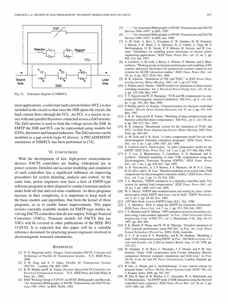
most applications, a solid state fault current limiter (FCL) is alsoincluded in the circuit so that once the SSB opens the circuit, thefault current flows through the FCL. An FCL is a reactor in se-ries with anti-parallel thyristors connected across a ZnO arrester.The ZnO arrester is used to limit the voltage across the SSB. InEMTP the SSB and FCL can be represented using models forGTOs, thyristors and lumped inductors. The ZnO arrester can bemodeled as a gap switch (type-92 device). A PSCAD/EMTDCsimulation of SSB/FCL has been performed in [74].
VI. CONCLUSIONS
With the development of fast, high-power semiconductordevices, FACTS controllers are finding widespread use inpower systems. Detailed and accurate modeling and simulationof such controllers has a significant influence on improvingprocedures for system planning, analysis and control. At thesame time, power engineers now have a host of EMTP-typesoftware programs at their disposal to conduct transient analysisunder both off-line and real-time conditions. As these programsincrease in their complexity, it is important to keep track ofthe basic models and algorithms, that form the kernel of theseprograms, so as to enable future improvements. This paperreviews currently available models for EMTP-type studies in-volving FACTS controllers that do not employ Voltage-SourcedConverters (VSCs). Transient models for FACTS that useVSCs will be covered in other publications of the IEEE WG15.05.02. It is expected that this paper will be a valuablereference document for practicing power engineers involved inelectromagnetic transient simulations.
REFERENCES
[1] N. G. Hingorani and L. Gyugyi, Understanding FACTS: Concepts andTechnology of Flexible AC Transmission Systems. N.Y.: IEEE Press,2000.
[2] Y. H. Song and A. T. Johns, Flexible AC Transmission Systems(FACTS). London, UK: IEE, 1999.
[3] R. M. Mathur and R. K. Varma, Thyristor-Based FACTS Controllers forElectrical Transmission Systems. N.Y.: IEEE Press and John Wiley &Sons, Inc., 2002.
[4] IEEE Working Group (15.05.07) on HVDC Bibliography and Records,“An Annotated Bibliography of HVDC Transmission and FACTS De-vices 1991–1993,” in BPA, WAPA, 1993.
[5] , “An Annotated Bibliography of HVDC Transmission and FACTSDevices 1994–1995,” in BPA, 1995.
[6] , “An Annotated Bibliography of HVDC Transmission and FACTSDevices 1996–1997,” in BPA, Jun. 1998.
[7] A. M. Gole, A. Keri, C. Kwankpa, E. W. Gunther, H. W. Dommel,I. Hassan, J. R. Marti, J. A. Martinez, K. G. Fehrle, L. Tang, M. F.McGranaghan, O. B. Nayak, P. F. Ribeiro, R. Iravani, and R. Las-seter, “Guidelines for modeling power electronics in electric powerengineering applications,” IEEE Trans. Power Del., vol. 12, no. 1, pp.505–514, Jan. 1997.
[8] S. Lefebvre, A. M. Gole, J. Reeve, L. Piliotto, N. Martins, and S. Bhat-tacharya, “Working group on dynamic performance and modeling of DCsystems and power electronics for transmission systems: report on testsystems for AC/DC interaction studies,” IEEE Trans. Power Del., vol.10, no. 4, pp. 2027–2034, Oct. 1995.
[9] B. K. Johnson, “Simulation of TSC and TSSC,” in IEEE Power Engi-neering Society, Winter Meeting, 2001, vol. 2, pp. 637–638.
[10] L. Prikler and G. Banfai, “EMTP models for simulation of shunt reactorswitching transients,” Int. J. Electrical Power Energy Syst., vol. 19, no.4, pp. 235–240, May 1997.
[11] T. T. Nguyen and W. D. Humpage, “TCR and SR compensators in com-posite electromagnetic transient simulation,” IEE Proc., pt. C, vol. 136,no. 3, pp. 195–205, May 1989.
[12] P. Parihar and G. G. Karady, “Characterization of a thyristor controlledreactor,” Electric Power Systems Research, vol. 41, no. 2, pp. 141–149,May 1997.
[13] C. K. K. Tang and D. R. Turner, “Modeling of large nonlinear loads andthyristor controlled shunt compensators,” IEE Proc., pt. C, vol. 138, no.6, pp. 505–517, Nov. 1991.
[14] B. K. Johnson, “Benchmark system for the simulation of TCSC andSVC,” in IEEE Power Engineering Society, Winter Meeting, 2002, NewYork, pp. 484–487.
[15] A. M. Gole and V. K. Sood, “A static compensator model for use withelectromagnetic transients simulation programs,” IEEE Trans. PowerDel., vol. 5, no. 3, pp. 1398–1407, Jul. 1990.
[16] S. Lefebvre and L. Gerin-Lajoie, “A static compensator model for theEMTP,” IEEE Trans. Power Syst., vol. 7, no. 2, pp. 477–486, May 1992.
[17] S. Y. Lee, S. Bhattacharya, T. Lejonberg, A. E. Hammad, and S.Lefebvre, “Detailed modeling of static VAR compensators using theElectromagnetic Transients Program (EMTP),” IEEE Trans. PowerDel., vol. 7, no. 2, pp. 836–847, Apr. 1992.
[18] A. N. Vasconcelos, A. J. P. Ramos, J. S. Monteiro, M. B. V. C. Lima,H. D. Silva, and L. R. Lins, “Detailed modeling of an actual static VARcompensator for electromagnetic transients studies,” IEEE Trans. PowerSyst., vol. 7, no. 1, pp. 11–19, Feb. 1992.
[19] J. A. Martinez, “EMTP simulation of a digitally-controlled static VArsystem for optimal load compensation,” IEEE Trans. Power Del., vol.10, no. 3, pp. 1408–1415, Jul. 1995.
[20] W. S. Meyer, “EMTP data modularization and sorting by class: a foun-dation upon which EMTP data bases can be built,” EMTP Newsletter,vol. 4, no. 2, pp. 28–40, Nov. 1983.
[21] ATP Rule Book, Leuven EMTP Center (Ed.) , Ed., 1990.[22] J. A. Martinez, “How to adopt the EMTP for classroom instruction,”
IEEE Trans. Power Syst., vol. 7, no. 1, pp. 351–358, Feb. 1992.[23] J. A. Martinez and N. Mohan, “ATP simulation of power electronics sys-
tems using a data-module approach,” in Proc. 32nd Universities PowerEngineering Conf. (UPEC’97), vol. 1, Manchester, U.K., Sep. 10–12,1997, pp. 495–498.
[24] P. K. Muttik, P. Wang, and M. W. H. Minchin, “Detailed simulation ofSVC transient performance using PSCAD,” in Proc. Int. Conf. PowerSystem Technology (PowerCon, 2000), Perth, Australia.
[25] A. C. S. de Lima, S. S. Wanderley, and R. M. Stephan, “Modeling astatic VAR compensator using EMTP,” in Proc. 38th Midwest Symp. Cir-cuits and Systems, vol. 2, Rio de Janeiro, Brazil, Aug. 13–16, 1996, pp.219–222.
[26] W. Geraldes, E. H. Rose, C. Machado, J. T. Honda, and P. M. Ven-dramini, “Static VAR compensator from Coxipo substation (Brazil),comparison between computer simulations and field tests,” in Proc.5th Int. Conf. AC and DC Power Transmission, London, England, pp.301–306.
[27] B. Das, A. Ghosh, and A. Sachchidanand, “A new control scheme fordynamic brake,” in Proc. 9th Nat. Power Systems Conf. (NPSC ’96), vol.2, Kanpur, India, 1996, pp. 501–507.
[28] W. Zhu, R. Spee, R. R. Mohler, G. C. Alexander, W. A. Mittelstadt, andD. Maratukulam, “An EMTP study of SSR mitigation using the thyristorcontrolled series capacitor,” IEEE Trans. Power Del., vol. 10, no. 3, pp.1479–1485, Jul. 1995.
1078 IEEE TRANSACTIONS ON POWER DELIVERY, VOL. 20, NO. 2, APRIL 2005
[29] C. Gama and R. Tenorio, “Improvements for power system perfor-mance: modeling, analysis and benefits of TCSCs,” in Proc. IEEEPower Engineering Society Winter Meeting , vol. 2, Singapore, 2000,pp. 1462–1467.
[30] A. R. M. Tenorio and N. Jenkins, “Use of EMTP-ATP MODELS lan-guage for modeling thyristor controlled series capacitors,” in Proc. Uni-versities Power Engineering Conf. (UPEC ’98), vol. 2, Edinburgh, UK,1998, pp. 679–682.
[31] A. R. M. Tenorio, J. B. Ekanayake, and N. Jenkins, “Modeling of FACTSdevices,” in Proc. IEE Conf. AC and DC Power Transmission, London,U.K., Apr./May 1996, pp. 340–345.
[32] H.-G. Han, J.-K. Park, and B.-H. Le, “Analysis of thyristor controlledseries compensator dynamics using the state variable approach of aperiodic system model,” IEEE Trans. Power Del., vol. 12, no. 4, pp.1744–1750, Oct. 1997.
[33] L. J. Bohmann and R. H. Lasseter, “Stability and harmonics in thyristorcontrolled reactors,” IEEE Trans. Power Del., vol. 5, no. 2, pp.1175–1181, Apr. 1990.
[34] H. A. Othman and L. Angquist, “Analytical modeling of thyristor con-trolled series capacitors for SSR studies,” IEEE Trans. Power Syst., vol.11, no. 1, pp. 119–127, Feb. 1996.
[35] B. K. Perkins and M. R. Iravani, “Dynamic modeling of a TCSC withapplication to SSR analysis,” IEEE Trans. Power Syst., vol. 12, no. 4,pp. 1619–1625, Nov. 1997.
[36] P. Mattavelli, G. C. Verghese, and A. M. Stankovic, “Phasor dynamics ofthyristor controlled series capacitor systems,” IEEE Trans. Power Syst.,vol. 12, no. 3, pp. 1259–1267, Aug. 1997.
[37] , “SSR analysis with dynamic phasor model of thyristor controlledseries capacitor,” IEEE Trans. Power Syst., vol. 14, no. 1, pp. 200–208,Feb. 1999.
[38] R. J. Davalos and J. M. Ramirez, “A review of a quasistatic and a dy-namic TCSC model,” IEEE Power Eng. Rev., vol. 20, no. 11, pp. 63–65,Nov. 2000.
[39] A. T. Johns and Q. Y. Xuan, “Digital study of thyristor controlled seriescapacitor compensated EHV transmission systems,” in IEEE Proc. 10thIEEE Regional Conf. Computer, Communication, Control and PowerEngineering (TENCON’93), pp. 263–265.
[40] M. R. Sultan, J. Reeve, and R. Adapa, “Transient Behavior of SystemsContaining FACTS Devices: Modeling of the Thyristor Controlled Se-ries Capacitor,”, EPRI Final Report TR-108191, 2149-15, Jul. 1997.
[41] M. Sultan, J. Reeve, and R. Adapa, “Combined transient and dynamicanalysis of HVDC and FACTS systems,” IEEE Trans. Power Del., vol.13, no. 4, pp. 1271–1277, Oct. 1998.
[42] T. F. Godart, A. F. Imece, J. C. McIver, and E. A. Chebli, “Feasibilityof thyristor controlled series capacitor for distribution substation en-hancements,” IEEE Trans. Power Del., vol. 10, no. 1, pp. 203–209,Jan. 1995.
[43] A. Ghosh and G. Ledwich, “Modeling and control of thyristor-controlledseries capacitors,” IEE Proc. Generation, Transmission, Distribution,vol. 142, no. 3, pp. 297–304, May 1995.
[44] S. Al-Senaidi, “An application of thyristor controlled series capacitor toselective pole switching,” Electric Power Components & Systems, vol.30, no. 8, pp. 14–20, Aug. 2002.
[45] O. M. Neto, P. C. A. Leao, and A. E. A. Araujo, “Controlled series com-pensation: dynamic performance under fault conditions,” in Proc. 32ndUniversities Power Engineering Conf. (UPEC’97), vol. 1, Manchester,U.K., Sep. 10–12, 1997, pp. 5–8.
[46] J. Ndayizamba, S. Lefebvre, and D. D. Xuan, “Torsional interaction inflexible AC transmission systems with a thyristor controlled series ca-pacitor,” in Proc. 5th Electrimacs, Modeling and Simulation of ElectricMachines, Converters & Systems, Saint Nazaire, France, Sep. 17–19,1996, pp. 1187–1192.
[47] E. A. Leonidaki, B. C. Papadias, N. D. Hatziargyriou, and S. Giorgas,“A physical laboratory model of a thyristor controlled series capacitor,”in Proc. 33rd Universities Power Engineering Conf., Edinburgh, U.K.,Sep. 8–10, 1997.
[48] O. M. Neto, R. A. Meneguim, F. D. Oliveira, and J. M. Oliveira, “Mod-eling of a thyristor controlled series capacitor in matlab environment,”in Proc. 32nd Univertsities Power Engineering Conf. (UPEC’97), vol.1, Manchester, UK, September 10–12, 1997, pp. 21–14.
[49] M. Sultan, J. Reeve, and R. Adapa, “Combined transient and dynamicanalysis of HVDC and FACTS systems,” in IEEE PES Winter Meeting,Tampa, Florida, Feb. 1–5, 1998.
[50] E. A. Leonidaki, N. D. Hatziargyriou, and G. J. Georgantzis, “Simulationof thyristor controlled series capacitors and subsynchronous studies,” inProc. 32nd Universities Power Engineering Conf. (UPEC’97), vol. 2,Manchester, U.K., Sep. 10–12, pp. 883–886.
[51] J. Ndayizamba, S. Lefebvre, and D. D. Xuan, “Efficient and flexiblethyristor controlled series capacitor simulation in EMTP-TACS,” in Pro-ceedings of 12th Power Systems Computation Conf, vol. 2, Dresden, Ger-many, Aug. 20–23, 1996, pp. 1122–1127.
[52] D. D. Xueqiang-Zhao, “Study of TCSC model and prospective appli-cation in the power systems of China,” in Proc. Int. Conf. Power Elec-tronics and Drive Systems, (PEDS’99), vol. 2, Kowloon, Hong Kong,1999, pp. 688–691.
[53] Y. Tanaka, H. Taniguchi, M. Egawa, H. Fujita, M. Watanabe, and H.Konishi, “Using a miniature model and EMTP simulations to evaluatenew methods to control and protect a thyristor controlled series com-pensator,” in Proc. 1999 Winter Meeting of IEEE Power EngineeringSociety, vol. 2, New York, pp. 1196–1201.
[54] H. Xueqiang-Zhao and H. Chen-Chen, “Circuit analysis of a thyristorcontrolled series compensation,” in Proc. 1999 Winter Meeting of IEEEPower Engineering Society, vol. 2, New York, pp. 1067–1072.
[55] M. Junya, I. Keiichi, T. Takeshi, and A. Minoru, “Dynamic performanceof a thyristor controlled series capacitor system,” in Proc. 31st Universi-ties Power Engineering Conf., vol. 3, Iraklio, Greece, 1996, pp. 961–964.
[56] L. F. W. De Souza, E. H. Watanabe, and M. Aredes, “GTO controlledseries capacitors: multi-module and multi-pulse arrangements,” IEEETrans. Power Del., vol. 15, no. 2, pp. 725–731, Apr. 2000.
[57] , “GTO controlled series capacitor,” in IEEE Power EngineeringSociety Winter Meeting, 2000, vol. 4, 2000, pp. 2520–2525.
[58] S. G. Jalali, R. A. Hedin, M. Pereira, and K. Sadek, “Stability modelfor the Advanced Series Compensator (ASC),” IEEE Trans. Power Del.,vol. 11, no. 2, pp. 1128–1137, Apr. 1996.
[59] S. G. Helbing and G. G. Karady, “Investigations of an advanced formof series compensation,” IEEE Trans. Power Del., vol. 9, no. 2, pp.939–947, Apr. 1994.
[60] B. Pilvelait, T. H. Ortmeyer, and D. Maratukulam, “Advanced seriescompensation for transmission system using a switched capacitormodule,” IEEE Trans. Power Del., vol. 8, no. 2, pp. 584–590, Apr.1993.
[61] A. A. Girgis, A. A. Sallam, and A. K. El-Din, “An adaptive protectionscheme for Advanced Series Compensated (ASC) transmission lines,”IEEE Trans. Power Del., vol. 13, no. 2, pp. 414–420, Apr. 1998.
[62] M. R. Iravani, P. L. Dandeno, K. H. Nguyen, D. Zhu, and D.Maratukulam, “Applications of static phase shifters in power sys-tems,” IEEE Trans. Power Del., vol. 9, no. 3, pp. 1600–1608, Jul. 1994.
[63] M. R. Iravani and D. J. Maratukulam, “Review of semiconductorcontrolled (static) phase shifters for power system application—part 1,”IEEE Trans. Power Syst., vol. 9, no. 4, pp. 1833–1839, Nov. 1995.
[64] , “Review of semiconductor controlled (static) phase shifters forpower system application—part 2,” IEEE Trans. Power Syst., vol. 9, no.4, Nov. 1994.
[65] D. J. Nyati, S. Eitzmann, M. Kappenman, J. VanHouse, D. Mohan, andA. N. Edris, “Design issues for a single core transformer thyristor con-trolled phase-angle regulator,” IEEE Trans. Power Del., vol. 10, no. 4,pp. 2013–2019, Oct. 1995.
[66] PSCAD/EMTDC Manual, Manitoba HVDC Research Centre, 2001.[67] K. K. Sen and M. L. Sen, “Introducing the family of Sen transformers:
a set of power flow controlling transformers,” IEEE Trans. Power Del.,vol. 18, no. 1, pp. 149–157, Jan. 2003.
[68] , “Comparison of the Sen transformer with the unified power flowcontroller,” IEEE Trans. Power Del., vol. 18, no. 3, pp. 1523–1533, Oct.2003.
[69] Z. Xu and C. Chen, “Damping subsynchronous resonance using animproved NGH SSR damping,” in IEEE Power Engineering SocietySummer Meeting, vol. 2, Edmonton, AB, Canada, 1999, pp. 780–785.
[70] L. Wang, “Simulations of prefiring NGH damping scheme on sup-pressing torsional oscillations using EMTP,” IEEE Trans. Power Syst.,vol. 12, no. 2, pp. 882–888, May 1997.
[71] G. E. Lee and D. L. Goldsworthy, “BPA’s Pacific AC inter-tie seriescapacitors: experience, equipment and protection,” IEEE Trans. PowerDel., vol. 11, no. 1, pp. 253–259, Jan. 1996.
[72] M. Kezunovic, M. Aganagic, S. McKenna, and D. Hamai, “Computingresponses of series compensation capacitors with MOV protection inreal-time,” IEEE Trans. Power Del., vol. 10, no. 1, pp. 244–251, Jan.1995.
[73] P. S. S. Holenarsipur, D. J. Christofersen, and N. Mohan, “Thyristorswitched arrester for improved protection of power system equipment,”in Proc. Winter Meeting of IEEE Power Engineering Society, vol. 2, NewYork, 1999, pp. 1009–1014.
[74] L. Palav and A. M. Gole, “On using the solid-state breaker in distri-bution systems,” in Proc. IEEE Canad. Conf. Electrical and ComputerEngineering, vol. 1, Waterloo, Ontario, May 1998, pp. 693–700.
FARUQUE et al.: REVIEW OF ELECTROMAGNETIC TRANSIENT MODELS FOR NON-VSC FACTS 1079
M. O. Faruque is a Ph.D. candidate in the Department of Electrical andComputer Engineering at the University of Alberta, Canada. He received theB.Sc.Engg. in 1992 from Chittagong University of Engineering and Technology(erstwhile BITC), Bangladesh and the M.Eng.Sc. degree in 1999 from theUniversity of Malaya, Malaysia in the area of power engineering.
His research interest includes FACTS, HVDC and Real-Time Digital simula-tion of Power Electronics and Power Systems.
Venkata Dinavahi (M’00) received the B.Eng. degree in 1993 from NagpurUniversity, India, and the M.Tech. degree in 1996 from the Indian Institute ofTechnology, Kanpur, India. He received the Ph.D. degree in 2000 in electricaland computer engineering from the University of Toronto, Canada.
Presently, he is an Assistant Professor at the University of Alberta, Edmonton,Alberta, Canada. His research interests include electromagnetic transient anal-ysis and real-time simulation and control. He is a Professional Engineer in theProvince of Alberta.
Surya Santoso (M’96–SM’02) earned the B.S. degree from Satya WacanaChristian University, Indonesia in 1992, and the MSE and Ph.D. degrees inelectrical and computer engineering from the University of Texas at Austin,Texas, in 1994 and 1996, respectively.
He re-joined the University of Texas at Austin as an Assistant Professor infall 2003. Prior to joining the University, he was a Consulting Engineer withElectrotek Concepts, Inc. in Knoxville, Tennessee for seven years. His primaryresearch interests include development of intelligent systems for analyzing rawpower quality measurement data, power system modeling and studies, and windpower. He co-authored Electric Power Systems Quality published by McGraw-Hill Professional Series in 2002.
Ram Adapa received the Ph.D. in electrical engineering from the University ofWaterloo, Ontario, Canada.
He joined the Electric Power Research Institute (EPRI), Palo Alto, Californiain June 1989. At EPRI, he is currently a Technical Manager, Increased PowerFlow, in the Transmission & Substations area of Power Delivery & MarketsSector. Prior to joining EPRI, he was a Staff Engineer in the Systems Engi-neering Department of McGraw-Edison Power Systems (presently known asCooper Power Systems), Franksville, Wisconsin. His areas of interest includeincreased power flow, dynamic thermal circuit ratings, FACTS, phasor measure-ments, grid operations, grid planning, and grid reliability.
Dr. Adapa is a Senior Member of the IEEE Power Engineering Society. Hereceived the 2001 IEEE Regional Outstanding Engineer award for Region 6 forhis outstanding contributions to the Power Engineering Profession and to theIEEE Power Engineering Activities in Region 6. He is a Registered ProfessionalEngineer in the State of Wisconsin.