This article has been accepted for inclusion in a future issue of this journal. Content is final as presented, with the exception of pagination.
IEEE TRANSACTIONS ON ROBOTICS 1
Decentralized Extended Information Filter forSingle-Beacon Cooperative Acoustic Navigation:
Theory and ExperimentsSarah E. Webster, Member, IEEE, Jeffrey M. Walls, Student Member, IEEE, Louis L. Whitcomb, Fellow, IEEE,
and Ryan M. Eustice, Senior Member, IEEE
Abstract—We report a decentralized extended information filter(DEIF) algorithm designed for single-beacon cooperative acousticnavigation of one or more client underwater vehicles. In single-beacon cooperative acoustic navigation, ranges and state informa-tion from a single reference source (the server) are used to improvelocalization and navigation of an underwater vehicle (the client).The ranges and state information are obtained using underwateracoustic modems and a synchronous-clock time-of-flight paradigm.Apart from the server’s acoustic data broadcasts, the client has noaccess to the server’s position or sensor measurements. We showthat at the instance of each range measurement update, the DEIFalgorithm yields identical results for the current vehicle state esti-mate as the corresponding centralized extended information filter(CEIF), which fully tracks the joint probability distribution be-tween the server and client. We compare the state estimation re-sults of the DEIF algorithm with that of a CEIF and three otherfilters reported in the literature. The evaluation is performed usingboth simulated data and an experimental dataset comprised of onesurface craft and two autonomous underwater vehicles.
Index Terms—Decentralized estimation, distributed robotsystems, information filters, marine robotics, networked robots.
I. INTRODUCTION
THIS paper reports the derivation, simulation, and experi-mental evaluation of a decentralized extended information
filter (DEIF) algorithm for single-beacon cooperative acousticnavigation. The DEIF is designed for use within an acousticunderwater navigation paradigm using synchronous clocks andone-way-travel-time (OWTT) measurements [1], [2], althoughthe DEIF’s formulation may have applicability in other low-
Manuscript received November 30, 2012; accepted March 7, 2013. This pa-per was recommended for publication by Associate Editor J. A. Castellanos andEditor W. K. Chung upon evaluation of the reviewers’ comments. This work wassupported in part by the National Science Foundation under Award IIS-0746455,Award ANT-1039951, Award ATM-0427220, and Award IIS-0812138.
S. E. Webster is with the Applied Physics Laboratory, University of Wash-ington, Seattle, WA 98105 USA (e-mail: [email protected]).
J. M. Walls is with the Department of Mechanical Engineering, University ofMichigan, Ann Arbor, MI 48109 USA (e-mail: [email protected]).
L. L. Whitcomb is with the Department of Mechanical Engineering, TheJohns Hopkins University, Baltimore, MD 21218 USA (e-mail: [email protected]).
R. M. Eustice is with the Department of Naval Architecture and MarineEngineering, University of Michigan, Ann Arbor, MI 48109 USA (e-mail:[email protected]).
Color versions of one or more of the figures in this paper are available onlineat http://ieeexplore.ieee.org.
Digital Object Identifier 10.1109/TRO.2013.2252857
Fig. 1. The minimum time between updates for each client using two-waytravel-time (TWTT) ranging (upper panel) is the cumulative sum of the TWTTfor each client. In contrast, the minimum time between updates for each clientusing OWTT ranging (lower panel) remains constant, regardless of the numberof clients.
throughput, distributed estimation applications outside of thisreported scenario.
In the subsea domain, our goal is to enable high-precisionabsolute navigation of underwater vehicles without expensivesensor suites, and for missions with length scales on the order of100 km. As the cost of underwater vehicles has decreased, it hasbecome tractable to deploy multiple vehicles to collect scientificdata in the world’s oceans. Deployments of multiple low-costvehicles enable the collection of datasets over length scales toolarge to be covered by a single vehicle or too dangerous to riskan expensively instrumented vehicle. However, the requirementto estimate the position of multiple vehicles simultaneously, es-pecially vehicles without expensive, state-of-the-art navigationsensors, provides a challenge for existing navigation systems.
Most underwater acoustic navigation systems are narrowbandand are based upon measuring two-way travel-time (TWTT)time-of-flight ranges [3], [4]. In these systems, each vehiclemust interrogate the acoustic network in order to obtain a time-of-flight measurement between it and all replying nodes. As aresult, as illustrated in Fig. 1, the rate at which multiple ve-hicles can receive navigation updates decreases linearly as thenumber of navigated vehicles in the water increases. In com-parison, OWTT ranging can be determined by knowing pre-cisely the transmit and receive times of an underwater acoustictelemetry packet. The result is a direct one-way time-of-flightmeasurement from source to receiver. Thus, when a server nodebroadcasts to the network, all receiving client nodes can pas-sively measure their one-way time-of-flight to the server node.The advantage over TWTT ranging is that OWTT ranging read-ily scales to a multi-vehicle environment within a server/clientarchitecture, because the overall update rate for each client
This article has been accepted for inclusion in a future issue of this journal. Content is final as presented, with the exception of pagination.
2 IEEE TRANSACTIONS ON ROBOTICS
remains constant. The disadvantage is increased complexity inthe hardware design because all nodes must carry synchronizedstable clock hardware.
In our work, we employ the Woods Hole Oceanographic In-stitution (WHOI) Micro-Modem, i.e., an underwater acousticmodem capable of synchronous-clock transmission [5], [6].This synchronous-clock feature allows the Micro-Modem todirectly and accurately measure time of arrival (TOA) betweena source and receiver when using a user-supplied external ref-erence clock. This common time base allows for a synchronousmodem communication/navigation system, whereby acoustictelemetry broadcasts can encode time of origin informationas well as local state information. Acoustic telemetry packetscan be broadcast to the vehicle network, allowing all receivingnodes to passively measure their OWTT to the source node.The OWTT-derived range knowledge, when used in conjunc-tion with the decoded acoustic telemetry data and other onboardvehicle navigation data, provides a mechanism to enable coop-erative acoustic navigation.
We have previously reported centralized algorithms forsynchronous-clock, OWTT, cooperative, acoustic navigationand evaluated their performance using experimental data fromboth shallow-water [2], [7] and deep-water field trials [8], [9]. Inthis paper, we present a novel decentralized algorithm, evaluateits performance with experimental data, and compare the re-sults with other commonly used estimation frameworks. Withinthe context of single-beacon navigation, the decentralized ap-proach provides a flexible, scalable solution for vehicle naviga-tion. Navigation algorithms that rely on a centralized observersuffer from the severely limited bandwidth and high latencyassociated with underwater acoustic communication in compar-ison with typical land-based radio frequency communicationnetworks [10]. Given the speed of sound in water (∼1500 m/s),transmitting acoustic data over ranges on the order of kilome-ters results in latency on the order of seconds. Although theuseful channel capacity of acoustic modem technology has in-creased dramatically in recent years, achieving throughput of upto 5000 bps [5], operationally the average throughput is on theorder of 10–50 bps due to the low duty cycle with which thesemessages are typically transmitted during deep-water at-sea op-eration [11]. The proposed DEIF is well suited to single-beaconnavigation over limited-capacity and high-latency underwateracoustic telemetry because this distributed approach only re-quires a small, fixed quantity of information to be transmittedfrom the server to the client.
The contributions of this study build primarily on our previouswork [12], [13] and include the following:
1) a detailed theoretical derivation and analysis of the DEIFalgorithm;
2) a comprehensive analysis of the DEIF algorithm based onsimulation and real-world experimental data;
3) a thorough comparison of the DEIF algorithm with otherOWTT navigation frameworks found in the literature andused throughout the community.
The DEIF algorithm reported herein consists of two parts.The first runs on the server, which is assumed to be a movingvehicle (a ship or another underwater vehicle, for example), but
the server could also be a fixed beacon. The second part is de-signed to run locally on a submerged vehicle, which is referred toas the client, with real-time access to the client’s own onboardnavigation sensors and infrequent, asynchronous reception ofacoustic broadcasts from the server vehicle. Notably, the clientdoes not have access to real-time measurements from the server,but only information that is contained in the server’s acousticbroadcasts. Note that we characterize this filter as “decentral-ized,” as opposed to “distributed” because we do not employ afusion center [14].
The rest of this paper is organized as follows: Section IIdescribes previous work in several relevant areas. Section IIIpresents the derivation of the DEIF and shows that it producesidentical results to that of a centralized extended information fil-ter (CEIF) (the dual equivalent of a centralized extended Kalmanfilter) immediately following each range measurement update.Sections IV and V present implementation details and resultsevaluating the performance of the DEIF and other reported ap-proaches, using both simulated data and real-world experimentaldata. This comparison is performed across several operationalscenarios, including when significant mutual correlation existsbetween the server and the client. Section VI discusses prac-tical considerations of the DEIF algorithm, and Section VIIconcludes this paper.
II. PREVIOUS WORK
The results in decentralized single-beacon cooperative navi-gation reported in this paper are informed by several areas of re-search, discussed below: single-beacon underwater navigation,decentralized multi-robot cooperative localization, decentral-ized estimation in the context of multiple underwater vehicles,and the use of the information filter for navigation in the generalfield of mobile robotics.
A. Single-Beacon Underwater Navigation
Single-beacon navigation relies on range measurements froma single beacon, which is referred to as the server, to provide aposition reference to one or multiple client vehicles. The server’sposition estimate is typically more accurate than that of theclients’ either through access to continuous or intermittent geo-referenced position information, e.g., from a global positioningsystem (GPS), or because the server has high fidelity sensors thatallow for more accurate dead-reckoning than the clients, e.g., ahigh-grade inertial measurement unit. The observability require-ments of such server–client networks are explored in [15]–[17].Any form of navigation that relies solely on range observationsfor localization is fundamentally limited by the geometry of thesource and receiver. However, the relative observability of thetwo vehicles can inform an intelligent server control strategy, asin [18], to drive down uncertainty in the client.
Navigation with a single, fixed beacon, whose position isknown a priori, has been reported using several different estima-tion techniques—a least-squares approach by Scherbatyuk [19]and Baccou and Jouvencel [20], and a vehicle-based extendedKalman filter (EKF) by Larsen [21] and Gadre and Stilwell [16].Navigation with respect to a moving reference beacon, whose
This article has been accepted for inclusion in a future issue of this journal. Content is final as presented, with the exception of pagination.
WEBSTER et al.: DECENTRALIZED EXTENDED INFORMATION FILTER FOR SINGLE-BEACON COOPERATIVE ACOUSTIC NAVIGATION 3
position is not known a priori, is reported by McPhail andPebody [22] using a nonlinear least-mean-squares method; byEustice et al. [2], [7] using a maximum likelihood estimationmethod; and by Webster et al. [8], [9] using a centralized ex-tended Kalman filter (CEKF). As reported, each of these meth-ods is only structurally tractable for post-processing, althoughthe authors of [2], [7], and [22] suggest improvements that wouldallow for real-time implementations. Morice and Veres [23] re-port geometric bounding techniques that are applicable in realtime, and simulation results for range-based underwater naviga-tion. See [8] for an extensive review of single-beacon navigation.
B. Cooperative Multi-robot Localization
As fielding teams of robots with complementary sensor char-acteristics has become more practical, research in decentralized,multi-robot cooperative localization has intensified. Roumelio-tis and Bekey [24] present a distributed EKF solution that tracksthe global state composed of all robot positions. Other dis-tributed approaches incorporating relative robot observationsinclude particle filters by Howard [25], and graph-based meth-ods by Kim et al. [26] and Indelman et al. [27]. These methodsrequire unconstrained bandwidth, a nonlossy communicationchannel, or both. These can be achieved in post-processing, butare impractical in real time for an underwater acoustic networkgiven the restrictions of the underwater acoustic channel [28].
Ribeiro et al. [29] and Nerurkar et al. [30] perform distributedcooperative localization only requiring the transmission of a sin-gle bit per measurement within their sign-of-innovation Kalmanfilter. This quantized method is able to construct an approxima-tion of the centralized filter onboard each platform, although isnot tolerant of a lossy channel.
A distributed information filter-based approach for multi-vehicle cooperative localization is proposed by Bailey et al. [31].Each vehicle in the network maintains a local pose-graph (agraph where edges are constraints and nodes are poses) thatfuses local measurements with observations of the relative-poseto other vehicles. A central fusion center then processes localpose-graphs and relative-pose observations to estimate the fulljoint distribution over all vehicle poses. To efficiently transmitlocal pose-graphs to the central server, the authors partition thelocal pose-graph into segments according to a “product-rule de-composition.” When the platform transmits new nodes within itspose-graph to a fusion center, this interplatform message compo-sition is equivalent to the delta information packets used hereinand first presented by Webster et al. [12]. The DEIF algorithmpresented herein is similar to the algorithm in [31] applied to thetwo-vehicle unidirectional communication topology. Our clientvehicle, however, runs a single filter, whereas [31] maintains aseparate client filter and fusion center.
Cooperative localization has also been addressed within thelarger framework of decentralized data fusion—see [32], forexample, and [14]. In the latter, the authors present a system thatemploys an information filter that uses a distributed Choleskymodification for delayed states. This enables individual clientsto share their local estimates within the network without theuse of a centralized fusion center. Another research area that
is related to multi-robot localization is the use of consensusalgorithms, for tasks such as cooperative multi-robot mapping[33].
C. Decentralized Underwater Multi-vehicle Navigation
Decentralized estimation in the context of underwater com-munication and navigation faces unique constraints in termsof low data rates and high latency, which renders many of thedecentralized estimation solutions from terrestrial applicationsunsuitable for use with underwater vehicles.
An approach to decentralized underwater navigation, whichis reported by Maczka et al. [34], treats each range measurementas originating from an independent source (to minimize acousticdata telemetry) and fuses them in a Kalman filter ignoring anycorrelation between the sender and receiver. The authors refer tothis method as the egocentric extended Kalman filter (EEKF),because it does not consider possible correlation between thenavigation estimates of each vehicle. This method has modestdata telemetry requirements, is robust to packet loss, and easilyscales to large networks; however, ignoring correlation amongthe vehicles can cause overconfidence and divergence, as isnoted [34], which states: “The complete system behavior whenthe cross covariance terms Pij are neglected is of great interest.These terms represent the information that is common betweenvehicles i and j. Neglecting them results in larger Kalman gainsfor each vehicle, overly optimistic covariance calculations, andcould result in the divergence of the Kalman filter. . ..”
Bahr et al. [35] address cooperative localization of multipleunderwater and surface vehicles using a bank of decentralizedvehicle-based filters. This study reports the use of multiple sur-face vehicles with access to GPS to provide range measurementsto the underwater vehicles. An acoustic broadcast from a sur-face vehicle encodes the mean and covariance estimate of thatvehicle, and multiple receiving vehicles use the acoustic broad-cast to perform a range measurement update. In order to avoidoverconfidence, the authors present a bookkeeping approach,which is referred to as the interleaved update (IU) algorithm,in which each vehicle runs multiple Bayes estimators that trackthe source of each range measurement.
In a separate work, Bahr et al. [36] present a multi-vehiclecooperative localization method that, as an expansion of themoving long baseline concept proposed by Vaganay et al. [37],encompasses multiple range sources and real-time operations.Fallon et al. [38] generalize [36] to consider navigation in thecontext of a single range source. Similar to our work, Fallonet al. [38] rely on a single, moving, georeferenced server to sup-port the localization of multiple vehicles through asynchronousacoustic broadcasts. The authors present a client-based EKF anda minimization strategy that uses current and historic server po-sitions, ranges between client and server positions (both currentand historic), and the distance traveled by the client betweenrange measurements. Like in the EEKF algorithm [34], theserver and clients are assumed to be uncorrelated, and rangemeasurement updates are performed using the absolute posi-tion and covariance of the server. One of the benefits of theformulation in [38] is that the algorithm is trivially robust to
This article has been accepted for inclusion in a future issue of this journal. Content is final as presented, with the exception of pagination.
4 IEEE TRANSACTIONS ON ROBOTICS
packet loss, although ignoring the correlation between clientsand server may lead to an overconfident estimate of the clientposition, as noted in [34].
In a separate work, Fallon et al. [39] present a measurementdistribution framework that allows multiple platforms to sharenavigation information (including intervehicle range measure-ments) to enable a fully consistent distributed solution. Theframework is based upon each node locally recreating the stateof the entire system using range measurements between nodesand knowledge of each node’s dead-reckoning between succes-sive range measurements. The method provides a bookkeepingmechanism that relies on acknowledgments between vehicles toeventually provide all of the requisite information to each node.Once a node has collected information for the entire system up toa certain time (range measurements and dead-reckoning infor-mation for all nodes), a fully consistent cooperative navigationsolution can be calculated. The convergence rate of this algo-rithm is sensitive to packet loss, as it requires the retransmissionof data packets that are not acknowledged.
D. Extended Information Filter for Navigation and SLAM
The Kalman filter in the inverse covariance form, which isknown as the information filter, has several properties that makeit a good candidate for navigation in multi-robot applications.Derived in detail by Mutambara [40], the extended informationfilter (EIF) has been employed in distributed form for terres-trial robot applications such as vehicle navigation by Bozorget al. [41], simultaneous localization and mapping (SLAM) byThrun and Liu [42] and Reece and Roberts [43], and multi-robot localization by Bailey et al. [31] (as described earlier).The EIF has also been used successfully within decentralizedestimation for linear systems with known network topologies byGrime et al. [44]. In the context of underwater vehicles, thereare examples of the EIF being employed in SLAM algorithmsby Eustice et al. [45] and in a distributed fashion by Diosdadoand Ruiz [46].
Nonlinear smoothing algorithms have become popular in theSLAM community due to advances in sparse linear-algebratechniques [47], [48]. A delayed-state filtering SLAM frame-work, such as [45] and the work reported herein, is also asmoothing framework over the delayed states. The key differ-ence being that nonlinear smoothing algorithms periodicallyrelinearize constraints, whereas a filter linearizes only once.Fallon et al. [49] present an underwater navigation algorithmfusing independent OWTT observations from a surface vehi-cle with side-scan in a nonlinear incremental smoothing andmapping framework (iSAM). In practice, the use of nonlinearfiltering frameworks that do not relinearize is widespread andknown to provide accurate estimates [50].
III. DECENTRALIZED EXTENDED INFORMATION FILTER
We consider the problem of estimating the pose of a clientvehicle given acoustic range observations from the server to theclient, as illustrated in Fig. 2. The CEKF [8], [9], which hasconcurrent access to sensor data from all vehicles, serves asthe “gold-standard” and is well suited to modeling this coop-erative localization problem for its ability to track correlation
Fig. 2. Server poses (circles) and client poses (triangles) are linked by therange measurement. As described later, at the time-of-arrival (TOA), the central-ized filter has access to the server’s measurements between the time-of-launch(TOL) and the TOA, whereas the DEIF does not.
between multiple vehicles. Although communicating the sen-sor measurements from each underwater vehicle in real timeto the CEKF is not (practically) feasible, many filtering opera-tions in the information form of the CEKF, i.e., the CEIF, haveproperties that lend themselves to distributed computation. TheDEIF algorithm provides a way to distribute the computation ofa CEIF for a server and client vehicle under a low bandwidthrequirement.
The implementation of the DEIF requires two separate fil-ters, each of which processes sensor data causally and asyn-chronously. The server-side filter has real-time access to its localsensor data only; it is independent of, and has no knowledge of,the client state, client sensor measurements, or range measure-ments. At the time-of-launch (TOL) of each acoustic broadcast,the server-side filter computes a compact fixed-size representa-tion of its state and uncertainty to transmit acoustically to theclient. As described by Webster et al. [51], the server-to-clientrange is measured using the OWTT of the acoustic broadcastassuming a known sound velocity profile. The client-side filterhas real-time access to the client’s sensor data and the asyn-chronous acoustic broadcasts from the server, but does not haveaccess to the server’s raw sensor measurements, except for theprocessed information contained in the server-to-client acousticbroadcasts. The DEIF algorithm allows the client filter to ex-actly reconstruct the CEIF/CEKF at the TOA of server acousticbroadcasts.
In the following, we present a review of the salient features ofthe CEIF that lead to its distributed operation within the DEIF.We then report the DEIF algorithm.
A. Extended Information Filter
The EIF is characterized by the information matrix Λ and theinformation vector η, which can be defined in terms of the meanμ and covariance Σ of the state vector x as
Λ = Σ−1 , η = Λμ (1)
where
Σ = E[(x − μ)(x − μ)�
], μ = E[x] (2)
and E[·] is the expectation operator [50].1) Process Prediction: For the general process prediction
equations, we consider a state vector with two terms in it: thecurrent state xk of a vehicle and a collection of delayed states(i.e., previous states) xp . The stacked vector xk represents the
This article has been accepted for inclusion in a future issue of this journal. Content is final as presented, with the exception of pagination.
WEBSTER et al.: DECENTRALIZED EXTENDED INFORMATION FILTER FOR SINGLE-BEACON COOPERATIVE ACOUSTIC NAVIGATION 5
combined state at time k given all data up through time k
xk =[x�
k , x�p
]�(3)
and has an associated information matrix and vector given by
Λk =[
Λkk Λkp
Λpk Λpp
], ηk =
[ηk
ηp
]. (4)
Here, Λii and ηi represent the blocks of the stacked informationmatrix Λk and vector ηk at time k, respectively, correspondingto state component xi∈{k,p}.
The process model predicting the state one time step ahead isgiven by
xk+1 = f(xk ,uk+1) + vk (5)
with distribution p(xk+1 ,xp |Z1:k ,U1:k+1), where
Λk+1 =[
Ψk Q−1k F kΩ−1
k Λkp
ΛpkΩ−1k F�
k Q−1k Λpp − ΛpkΩ−1
k Λkp
](6)
ηk+1 =[
Q−1k F kΩ−1
k ηk + Ψk
(f(μk ,uk+1) − F kμk
)
ηp − ΛpkΩ−1k η�
k
]
. (7)
Here, Z1:k is the set of sensor measurements up through time k,U1:k+1 is the set of control inputs up through time k + 1, f(·) isthe nonlinear process model with Jacobian F k (evaluated aboutμk ), Qk is the covariance of the zero-mean Gaussian processnoise vk , and, for notational convenience,
Ψk = (Qk + F kΛ−1kk F�
k )−1 (8)
Ωk = Λkk + F�k Q−1
k F k (9)
η�k = ηk − F�
k Q−1k
(f(μk ,uk+1) − F kμk
)(10)
as derived by Eustice et al. [45].The blocks of the information matrix and vector correspond-
ing to past states, Λpp and ηp , respectively, are only changed byan additive term when they are propagated forward in time. Fora linear process model, the additive term can be calculated with-out linearization or need for the current mean. Furthermore, allother blocks of the information matrix and vector are changedin a way that does not depend on the information of the paststates.
2) Process Prediction With Augmentation: In (6) and (7),the current state at time k is propagated to time k + 1 so that
xk+1 =[x�
k+1 , x�p
]�. (11)
If we augment the stacked state vector to include the state attime k + 1 in addition to the original states
xk+1 =[x�
k+1 , x�k , x�
p
]�(12)
then the process prediction equations, which represent the distri-bution p(xk+1 ,xk ,xp |Z1:k ,U1:k+1), have a different structuredescribed by
Λk+1 =
⎡
⎢⎣
Q−1k −Q−1
k F k 0
−F�k Q−1
k Ωk Λkp
0 Λpk Λpp
⎤
⎥⎦ (13)
ηk+1 =
⎡
⎢⎣
Q−1k
(f(μk ,uk+1) − F kμk
)
η�k
ηp
⎤
⎥⎦ (14)
where the above equations use the same variable definitions asin (6) and (7). Equations (13) and (14) can each be written asthe sum of two terms:
Λk+1 =
⎡
⎢⎣
Q−1k −Q−1
k F k 0
−F�k Q−1
k F�k Q−1
k F k 0
0 0 0
⎤
⎥⎦
+
⎡
⎢⎣
0 0 0
0 Λkk Λkp
0 Λpk Λpp
⎤
⎥⎦ (15)
ηk+1 =
⎡
⎢⎣
Q−1k
(f(μk ,uk+1) − F kμk
)
−F�k Q−1
k
(f(μk ,uk+1) − F kμk
)
0
⎤
⎥⎦
+
⎡
⎢⎣
0
ηk
ηp
⎤
⎥⎦ . (16)
The first term contains the process prediction information andthe second term contains the prior information (4) at time k,but padded with zeros corresponding to the state at time k + 1.These zeros reflect that at time k, prior to prediction, there isno information about the state at time k + 1. This operation ispurely additive and, in fact, only modifies the Λkk and ηk blocksof the original information matrix and vector.
As observed by Eustice et al. [45], prediction with augmenta-tion results in Λk+1 having a sparse, block-tridiagonal structure.The sparsity of Λk+1 is important in the context of acoustic nav-igation because it bounds the amount of information that mustbe acoustically transmitted from the server to the client in orderfor the client to fully reconstruct the server’s estimated state (seeSection III-C).
3) Measurement Update: The observation model is
zk = h(xk ) + wk (17)
which leads to an updated posterior, i.e., p(xk ,xp |Z1:k ,U1:k ),that is parametrized by
Λk = Λk + H�k R−1
k Hk (18)
ηk = ηk + H�k R−1
k
(zk − h(μk ) + Hk μk
)(19)
where zk is the measurement vector, Rk is the covariance matrixof the zero-mean Gaussian measurement noise wk , and h(·) isthe nonlinear measurement model with Jacobian Hk (evaluatedabout μk ) [45].
The information matrix is additively updated by the matrixouter product H�
k R−1k Hk . In general, the measurement Jaco-
bian Hk is sparse resulting in an update step that only affectsa few subblocks of the information matrix and vector. Onboardnavigation sensor observations at the server or client only mod-ify, respectively, the server state or client state. Range measure-
This article has been accepted for inclusion in a future issue of this journal. Content is final as presented, with the exception of pagination.
6 IEEE TRANSACTIONS ON ROBOTICS
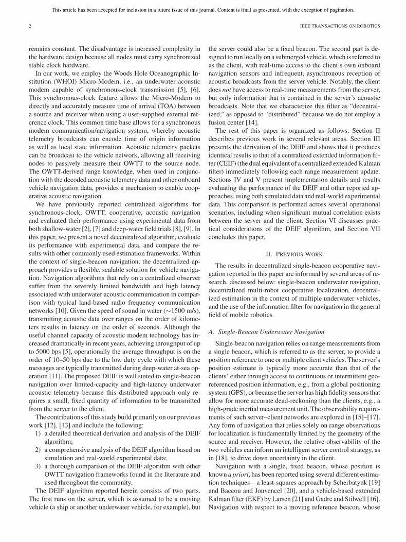
Fig. 3. Graphical comparison of the CEIF and the DEIF’s server and client filters. In each sequence, the “+” and “×” indicate additive and nonadditive operations,respectively. Red and black operators designate operations performed by the server and client vehicles, respectively. The gray areas in the first and last panels depictthe nonzero sparsity pattern of the information matrix. Both the server and client DEIF filters track a portion of the centralized state vector, with the client-sideDEIF achieving equality with the CEIF (for the states they share in common) immediately following the range measurement update.
ments between the server and the client change both the currentclient state and the delayed server state.
B. Centralized Extended Information Filter Operation
The CEIF is simply the information form dual [40] of theCEKF [8], [9]. It processes sensor data from all vehicles causallyand asynchronously in real time.
1) Centralized Extended Information Filter State Vector:Since range measurements are generally made between serverTOL states and client TOA states, the CEIF tracks a stackedstate vector containing the current server and client states, aswell as copies of the TOL server states. At each acoustic TOL, acopy of the server state is appended onto the state vector via theprediction with augmentation operation (14). After n acousticbroadcasts, the state vector consists of
xk =[x�
sk, x�
sTOLn, . . . , x�
sTOL2, x�
sTOL1, x�
ck
]�(20)
where we use the following notation: xk denotes the entirestacked state at time k; xsk
and xckare the current server and
client states, respectively; and xsTOLiis the server state at the ith
TOL. We note that this delayed-state framework is a smoothingalgorithm, as TOL delayed states benefit from new information.
Before the first server-to-client broadcast, the informationmatrix is block diagonal between the server and client, as thevehicles have shared no information. Since initially each vehi-cle state evolves independently of the other vehicle, the CEIFoperation mirrors the operation of two independent informationfilters, each tracking one vehicle.
2) Server-to-Client Broadcasts: At the TOA of server broad-cast, the client measures the OWTT-derived range to the server.The observation model for the range measurement is
zk =∥∥∥xcTOAx y z
− xsTOLx y z
∥∥∥ + wk (21)
where “xyz” indicates the position components of the client andserver state vectors, and wk ∼ N (0, Rk ) is the measurementnoise. Noise in the range measurement is a result of several
nonlinear error sources including multipath and timing impreci-sion. The error distribution, while strictly non-Gaussian, is com-monly modeled as Gaussian [18], [52], [53] following an outlierrejection step. As mentioned previously, the range measurementJacobian is sparse, as it only involves the client TOA positionand the server TOL delayed state. Therefore, only blocks of theinformation matrix and vector corresponding to these states aremodified during the measurement update.
Following the first range measurement update, the informa-tion matrix contains nonzero off-diagonal blocks between theserver TOL state (i.e., a delayed state) and the current clientstate. However, because of the structure of prediction in theinformation form, the current server state information evolvesin a way that does not depend on its delayed state given a lin-ear server process model [see (6) and (7)], and the block ofthe information matrix corresponding to the delayed state onlychanges additively. Moreover, measurement updates for the cur-rent server state do not depend on its delayed state given linearobservation models. This implies that the server accumulatesinformation (through prediction and measurement updates withlinear models) independent of the range measurement update.The CEIF operation is illustrated in Fig. 3.
The above understanding motivates the design of the DEIF al-gorithm, which distributes the CEIF server prediction and mea-surement updates to a filter running onboard the server, while aseparate filter running onboard the client processes client pre-diction and measurement updates, including range measurementupdates.
C. Server-Side DEIF Operation
The server-side filter has real-time access to sensor dataonly from server-based sensors; it is independent of the clientstate, client sensor measurements, and range measurements. Theserver-side implementation is described in Algorithm 1.
1) Server-Side Decentralized Extended Information FilterState Vector: The standalone server filter maintains an estimate
This article has been accepted for inclusion in a future issue of this journal. Content is final as presented, with the exception of pagination.
WEBSTER et al.: DECENTRALIZED EXTENDED INFORMATION FILTER FOR SINGLE-BEACON COOPERATIVE ACOUSTIC NAVIGATION 7
of the current server state as well as copies of TOL server states.Each time a new acoustic range packet is broadcast (i.e., at theTOL), a copy of the current server state is appended onto thestate vector. This results in a state vector, after n acoustic packetshave been transmitted, of the form
xsk=
[x�
sk, x�
sTOLn, . . . , x�
sTOL2, x�
sTOL1
]�(22)
where we have adopted the following notation convention: xsk
denotes the entire stacked server state at time k; xskis the
current server state; and xsTOLiis the server state when the
ith range packet was broadcast. The corresponding informa-tion matrix has a sparse, block tridiagonal structure. As in theCEIF, only the blocks of the information matrix correspondingto the current server state and the most recent TOL delayed stateare affected by predictions and measurement updates—changesin the information matrix and vector are constrained betweensuccessive TOLs.
In addition to the information matrix Λskand vector ηsk
thatcharacterize the current server state xsk
, a copy of the infor-mation matrix and vector at the last TOL are also stored (i.e.,ΛsTOLn −1
and ηsTOLn −1). This allows the server to compute the
difference in the information matrix and vector between TOLs,which is termed the “delta information.”
2) Delta Server Information for Acoustic Transmission: Toinitiate a range measurement, the server broadcasts a rangepacket containing delta information about the server state. Thisdelta information encapsulates all information gained via pre-dictions and measurement updates about the server state sincethe last TOL
ΔΛsTOLn −1 :n= ΛsTOLn
− Λ′sTOLn −1
(23)
ΔηsTOLn −1 :n= ηsTOLn
− η′sTOLn −1
(24)
where Λ′sTOLn −1
and η′sTOLn −1
represent the information at the lastTOL but padded with zeros to match the dimension of ΛsTOLn
and ηsTOLn. The zero padding represents the fact that at the last
TOL, the server had no information about its state at the nextTOL. These range packets are processed onboard the client-sideDEIF to reconstruct the CEIF, as described in Section III-D.
The calculation and transmission of delta server information,as described here, allows us to delegate the task of processing
server sensor data in the CEIF to an independent server-sideDEIF. The server-side DEIF operation is depicted in Fig. 3.
D. Client-Side DEIF Operation
The client-side DEIF has real-time access to the client’s on-board sensor data and the asynchronous range packets fromthe server but does not have access to the server’s raw sensormeasurements; the only server state information available to theclient is that which is encoded in the server-to-client acousticbroadcasts. The client-side DEIF reconstructs a local copy of theserver-state by sequentially incorporating information encapsu-lated in the acoustic broadcasts. The client-side implementationis described in Algorithm 2.
1) Client-Side State Vector: In addition to the current clientstate, the DEIF maintains a copy of historic server states recon-structed from the delta information broadcasts. As a result, theDEIF state vector consists of two parts: the current client stateand the TOL server delayed states
xck=
[x�
sTOLn −1, . . . , x�
sTOL2, x�
sTOL1, x�
ck
]�(25)
where we adopt the convention that xckdenotes the entire
stacked client state vector at time k; xckis the current client
state; and xsTOLiis the server TOL state when the ith acoustic
packet was broadcast. The client-side DEIF maintains the samestate vector as the CEIF with the exception that the client-sideDEIF does not track the current server state xsk
. We also notethat, unlike the server, the client is able to use nonlinear processand observations models, as in [12]. The client vehicle is alsofree to add delayed-state client poses in order to estimate itssmooth trajectory.
2) Incorporating Delta Server Information: At the TOA of arange packet onboard the client, the delta information includedin the packet is incorporated followed by the range measurementupdate. The delta information is incorporated into the client-sideDEIF by simple addition, in the analogous operation to (23) and(24):
ΛcTOAn= Λ′
cTOAn+ ΔΛsTOLn −1 :n
(26)
ηcTOAn= η′
cTOAn+ ΔηsTOLn −1 :n
(27)
where Λ′cTOAn
is the client information matrix at the currentTOA before the delta information is incorporated, and ΛcTOAn
is the client information matrix at the current TOA after thedelta information is incorporated. The client-side information is
This article has been accepted for inclusion in a future issue of this journal. Content is final as presented, with the exception of pagination.
8 IEEE TRANSACTIONS ON ROBOTICS
padded with zeros to reflect that, prior to incorporating the deltainformation packet, the client has no information regarding thenewest TOL server state.
3) Range Measurement Updates: At the TOA of the rangepacket, after the delta information is incorporated, the rangemeasurement update is performed. This operation is equiva-lent to the corresponding operation in the CEIF. As noted inSection III-C2, the delta information encapsulates all of the in-formation that the filter has gained about the server state sincethe last acoustic packet was broadcast. The simplicity of thiscomputation is one of the advantages of the information filter.The client-side DEIF operation is depicted in Fig. 3.
E. Equivalency of DEIF and Centralized Filter
Immediately after performing a range update, the client-sideDEIF is identical to the equivalent centralized filter (CEIF orCEKF) estimate for the states that they have in common. Thereare several subtleties in this observation that we address here forclarity.
1) Filter Distributions: A range measurement is an obser-vation between the server position at the TOL and the clientposition at the (later occurring) TOA, i.e., xsTOL
and xcTOA, re-
spectively. Comparing the probability distributions of the cen-tralized filter and DEIF immediately after the range measure-ment update, we find that they are not strictly identical:
DEIF :
p(xcTOA
,xsTOL
∣∣zrTOA
,Z1:TOAc ,U1:TOA
c , Z1:TOLs , U1:TOL
s
)
(28)
Centralized :
p(xcTOA
,xsTOL
∣∣zrTOA
,Z1:TOAc ,U1:TOA
c , Z1:TOAs , U1:TOA
s
)
(29)
where zrTOAis the most recent OWTT range measurement,
Z1:TOAc is the set of client sensor measurements up to the TOA,
U1:TOAc is the set of client control inputs up to the TOA, Z1:TOL
s
is the set of server sensor measurements up to the TOL, andU1:TOL
s is the set of server control inputs up to the TOL. Notethat the centralized filter has access to the server’s sensor mea-surements and control inputs between the TOL and the TOA ofwhich the DEIF has no knowledge (see Fig. 2).
The ramifications of this are that the DEIF performs a rangemeasurement between the current client state and the best esti-mate of the server’s state at the TOL given server sensor mea-surements and control inputs only up to the TOL. In contrast,the centralized filter performs a range measurement between thecurrent client state and the best estimate of the server’s state atthe TOL given server sensor measurement and control inputs upto the TOA. Thus, the centralized filter is performing a smooth-ing operation on the server’s state at the TOL, because it hasaccess to additional information from the server’s sensors afterthe data packet was broadcast.
2) Two-Step Delayed Update: To address this apparent dis-crepancy and to provide a fair comparison of the DEIF and the
CEIF in our experiments, we use a two-step delayed update inthe centralized filter. First, we perform an update for the rangemeasurement with only server measurements and control inputsup through the TOL:
p(xcTOA
,xsTOL
∣∣zrTOA
,Z1:TOAc ,U1:TOA
c ,Z1:TOLs ,U1:TOL
s
).
(30)Second, we perform another update for the server using mea-surements and control inputs occurring between the TOL andthe TOA (see Fig. 2):
p(xcTOA
,xsTOL
∣∣zrTOA
,Z1:TOAc ,U1:TOA
c ,Z1:TOLs ,U1:TOL
s ,
ZTOL:TOAs , UTOL:TOA
s
). (31)
This provides a fair comparison so that the DEIF distributionin (28) is identical to the centralized filter distribution in (30),without compromising the centralized filter’s final distribution,i.e., (31) is identical to (29).1
Between range measurements, the centralized filter and DEIFestimates of the client’s state will not be identical. Correlationthat develops between the client and server states causes newserver measurements to smooth the client state in the central-ized case. Since these server measurements are not immediatelyavailable to the client-side DEIF, no smoothing occurs untilafter a delta information packet is received. However, at theinstant immediately after each range measurement update, thefilter estimates will be identical (when using the two-step de-layed update) because the information contained in the deltainformation represents all previous server measurements.
F. Ramifications of Filter Design
A final note on this derivation, which is mentioned briefly inSection III-B, is that the server’s process and observation mod-els must be linear in order for the delta information calculatedonboard the server to match the delta information that would becalculated in the equivalent CEIF. Linear plant and observationmodels guarantee that the process prediction and measurementupdates are independent of the server’s current state. Thus, thecalculated delta information is independent of the actual valueof the state. This is essential because the standalone server filterwill have a different estimate of the server’s current state thanthe CEIF, a result of the CEIF’s server estimate being condi-tioned on previous range measurements. In contrast, there is nolinearity requirement for the client models, as shown in [12],which employs a six-degree-of-freedom (DOF) nonlinear pro-cess model for the client.
It is also worth noting that, in practice, it is undesirable, andunnecessary, for the state vector dimension to grow withoutbound, as per (22) and (25). Instead, we marginalize out theoldest historic server states on both the server and the clientin order to maintain a fixed-length state vector dimension [45].
1From an implementation perspective, we augment the centralized state vectorwith copies of the server state at every measurement event between the TOL andthe TOA to achieve a premarginalized equivalent of (29) and then retroactivelyapply the TOL to TOA server measurements, followed by marginalizing out theextra server states to arrive at (31).
This article has been accepted for inclusion in a future issue of this journal. Content is final as presented, with the exception of pagination.
WEBSTER et al.: DECENTRALIZED EXTENDED INFORMATION FILTER FOR SINGLE-BEACON COOPERATIVE ACOUSTIC NAVIGATION 9
Fig. 4. Algorithm performance is tested using two different two-node topolo-gies: Scenario A, where the server (shown as a ship) has continuous access toGPS, and Scenario B, where the server (shown as an AUV) has only intermittentaccess to GPS.
Minimally, the most recent TOL delayed state must be keptin the stacked state vector in order for the delta informationcomputation to be carried out correctly.
IV. IMPLEMENTATION DETAILS
The results described herein illustrate two points. First, wedemonstrate the numerical equivalence of the DEIF and theCEIF, which was established analytically in Section III. Second,we compare the performance of the DEIF with several alternatefiltering approaches reported in the literature. The comparison,which is similar to that presented by Walls and Eustice [13],is performed in post-processing between a pure dead-reckoned(DR) algorithm, a CEIF/CEKF, an EEKF, the IU algorithm, anda simple EKF that broadcasts the GPS position of the server ineach acoustic packet instead of filtering the server state. The statedescription and process model, as well as the implementationof these filters, are described below.
The different filter frameworks are compared using both sim-ulated and real-world experimental data for two operational sce-narios illustrated in Fig. 4: a server that has continuous access toGPS (e.g., a support ship or surface buoy), and a server that doesnot have continuous access to GPS (e.g., one autonomous un-derwater vehicle (AUV) surfacing intermittently to receive GPSupdates, while supporting a continuously submerged AUV).
A. Vehicle State Description
Since attitude and depth are easily instrumented with boundederror, we consider only x, y horizontal position estimation dur-ing our experiments. Range measurements can easily be pro-jected to the local-level plane with knowledge of relative ve-hicle depth. Furthermore, it is advantageous to represent thevehicle state with the smallest dimension possible to minimizebandwidth requirements for transmitting state information overthe acoustic channel. Results using a full 6-degree-of-freedom(DOF) nonlinear process model with the DEIF have been pre-viously reported by Webster et al. [12]. Further discussions onthe justification and ramifications of using this simplified statemodel for the server and client are covered in Section VI.
We employ a 2-DOF process model for both the server andthe client vehicles
x = [x, y, x, y]� (32)
where the platform position in the local-level plane is denotedby the x, y pair, and the corresponding world-frame velocitiesare x and y.
Each filter is implemented using a constant-velocity linearprocess model resulting in a one-step prediction of the form
xk+1 = F kxk + vk . (33)
Here, F k is the discrete-time linear state transition matrix:
F k =[
I IΔT
0 I
](34)
where ΔT is the period between time steps.
B. Filter Implementations
We have implemented four filters and a DR filter for compar-ison with the DEIF algorithm. Each is briefly described below.We employ the convention of using “s” and “c” subscripts todesignate the server and client states, respectively.
1) Centralized Extended Information Filter: The CEIFserves as our benchmark gold-standard solution. The CEIF is apost-processing formulation that has access to all sensor mea-surements from all vehicles and tracks the stacked state of theserver and client platforms:
x = [x�s ,x�
c ]�. (35)
Since the CEIF is the dual equivalent of the CEKF (each is theinverse of the other), for ease of comparison, we implement theCEKF algorithm, as reported in [8] and [9]. For cohesivenesswith the previous discussion, throughout our results, we referto this CEKF generated result as the CEIF. The estimated meanand covariance of the equivalent CEIF are
μ =[
μs
μc
], Σ =
[Σss Σsc
Σcs Σcc
]. (36)
The mean and covariance follow the standard Kalman predictionequations with a combined state transition matrix F k and noisecovariance matrix Qk given by
F k = blkdiag(F sk,F ck
) (37)
Qk = blkdiag(Qsk,Qck
). (38)
To correctly model range measurement updates, the CEIF aug-ments the global state to include the server state at TOL
x′ = [x�s ,x�
c ,x�sTOL
]�. (39)
This allows the filter to perform a standard nonlinear Kalmanupdate with the OWTT observation, as in (21). Once the mea-surement update has been completed, the augmented TOL statecan be marginalized out in order to maintain a bounded statevector dimension.
Initially, the navigation estimates of each vehicle are uncor-related so that the global covariance matrix is block diagonal.However, sharing intervehicle range measurements builds cor-relation between vehicle navigation estimates [13]. The CEIFtracks this correlation because it has access to all measurementsfrom all platforms.
2) Egocentric Extended Kalman Filter: The egocentric dis-tributed approach assumes that each range measurement origi-nates at an independent source. This is essentially equivalent to a
This article has been accepted for inclusion in a future issue of this journal. Content is final as presented, with the exception of pagination.
10 IEEE TRANSACTIONS ON ROBOTICS
CEKF with all of the off block-diagonal elements of the covari-ance matrix actively held to zero. Distributing this filter simplyrequires that the server transmit its local mean and covarianceμs and Σs , respectively. Acoustic data packets are constant size,as only local information is transmitted. Therefore, the EEKFcan trivially scale up to arbitrarily large networks and is robustto packet loss. However, because internode correlation is nottracked, this method can result in an overconfident estimate ofuncertainty [34].
In order to perform a range measurement update, the clientconstructs a combined state vector and covariance matrix byappending the transmitted statistics of the server
μ′c =
[μc
μs
]Σ′
c =[Σcc 0
0 Σss
]. (40)
The measurement update then proceeds with the standardKalman update with the measurement model given in (21).Following the update, the state elements corresponding to theserver are marginalized out. Note that this filter does not trackcorrelation; the next range update will follow the same updateprocedure assuming no correlation, resulting in a double count-ing of information because the client’s state has already beeninformed by the server’s state.
3) Interleaved Update Algorithm: Bahr et al. [35] proposethe IU algorithm as a solution to the problem of inconsistencyseen in the EEKF. To avoid overconfidence, the IU algorithmmaintains a set of different vehicle navigation estimates and onlyperforms range measurement updates between estimates that areknown to be uncorrelated. The IU algorithm is a bookkeepingapproach that can be employed with any filtering modality (e.g.,EKF, particle filter, unscented Kalman filter). For comparisonwith the other acoustic navigation frameworks considered inthis paper, we present the IU as applied to an EKF.
Under the IU framework, each platform maintains a bank ofEKFs. At time k, the set of state vectors and covariance matricestracked by the ith vehicle, which are denoted Ui(k) and Σi(k),respectively, are defined as
Ui(k) ={μ1
i (k), . . . ,μ2v −1
i (k)}
(41)
Σi(k) ={Σ1
i (k), . . . ,Σ2v −1
i (k)}
(42)
where v is the total number of vehicles in the network. Eachplatform also stores the origin of every acoustic broadcast ina transmission matrix T , where each row represents a filterwithin its local set and each column corresponds to a vehicle inthe network. Entries T ij represent the last time that the ith filterused the jth vehicle to update its navigation estimate. During anacoustic broadcast, each source node transmits its transmissionmatrix, as well as its entire bank of filters. A receiving node up-dates each of its filters by searching for a filter in the transmittedset that does not contain an update that could be correlated.This ensures that double counting of information will not occurwhere correlation could exist. The full mechanics of this updatestep are described in [35].
In a two-vehicle network with unidirectional communication,range measurement updates are performed using the server’stransmitted state estimate and a client state estimate that has
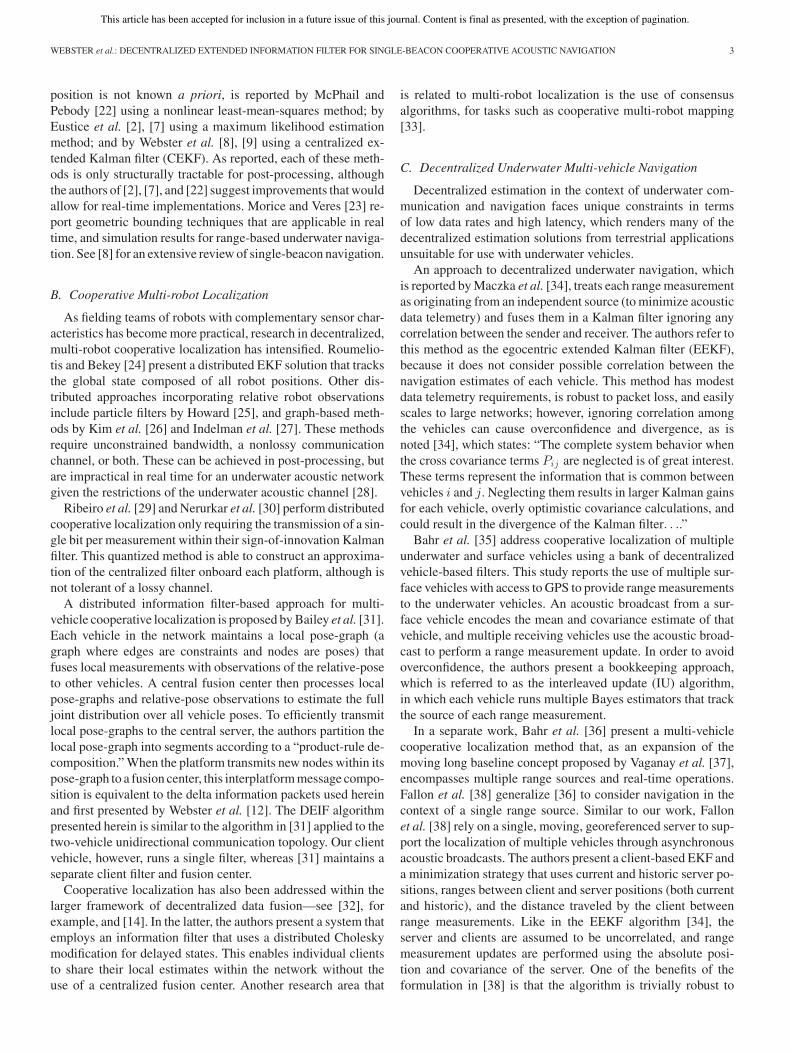
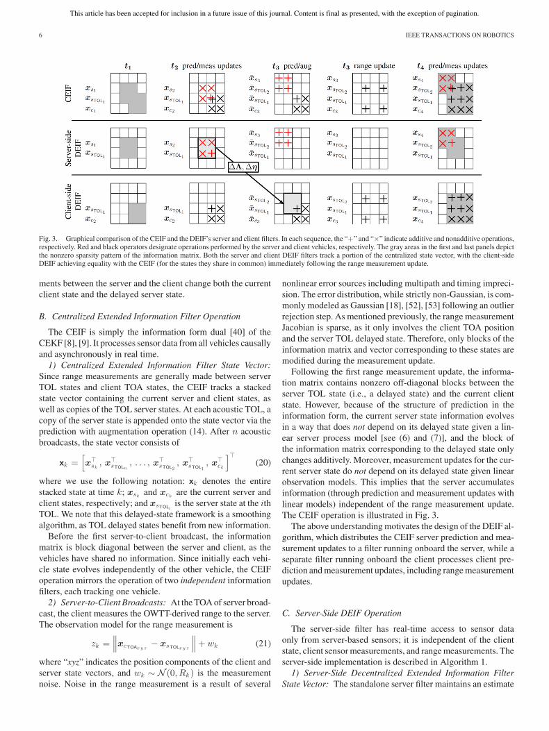
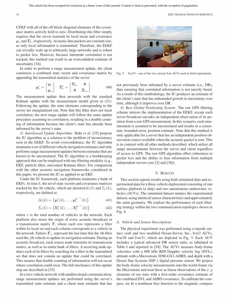
Fig. 5. Iver31—one of the two custom Iver AUVs used in field experiments.
not previously been informed by a server estimate (i.e., DR),thus ensuring that correlated information is not naively fused.As a result of this methodology, the IU produces an estimate ofthe client’s state that has unbounded growth in uncertainty overtime, although it improves over DR.
4) Raw Global Positioning System: The raw GPS filteringscheme mirrors the implementation of the EEKF, except eachserver broadcast encodes an independent observation of its po-sition from a raw GPS measurement. In this scenario, each mea-surement is assumed to be uncorrelated and results in a consis-tent, bounded-error, position estimate. Note that this method isonly applicable for a server that has an independent position ob-servation source available when the acoustic packet is sent. Thisis in contrast with all other methods described, which utilize allrange measurements between the server and client regardlessof access to GPS. The raw GPS algorithm offers robustness topacket loss and the ability to fuse information from multipleindependent servers (see [2] and [36]).
V. RESULTS
This section reports results using both simulated data and ex-perimental data for a three-vehicle deployment consisting of onesurface platform (a ship) and two autonomous underwater ve-hicles (AUVs). The simulated dataset mimics the experimentaldataset, using identical sensor characteristics and approximatelythe same geometry. We explore the performance of each filter-ing strategy within the two communication topologies shown inFig. 4.
A. Vehicle and Sensor Descriptions
The physical experiment was performed using a topside sur-face craft and two modified Ocean-Server, Inc., Iver2 AUVs,Iver28 and Iver31, which are depicted in Fig. 5. Each AUVincludes a typical advanced DR sensor suite, as tabulated inTable I and reported in [54]. The AUVs measure body-framevelocities with a 600 kHz RDI Doppler velocity log (DVL),attitude with a Microstrain 3DM-GX1-AHRS, and depth with aDesert Star Systems SSP-1 digital pressure sensor. We projectthe body-frame velocity measurements into the world-frame viathe Microstrain and treat these as linear observations of the x, yelements of our state with a first-order covariance estimate ofthe combined DVL and AHRS covariance. To calibrate the com-pass, we fit a nonlinear bias function to the magnetic compass
This article has been accepted for inclusion in a future issue of this journal. Content is final as presented, with the exception of pagination.
WEBSTER et al.: DECENTRALIZED EXTENDED INFORMATION FILTER FOR SINGLE-BEACON COOPERATIVE ACOUSTIC NAVIGATION 11
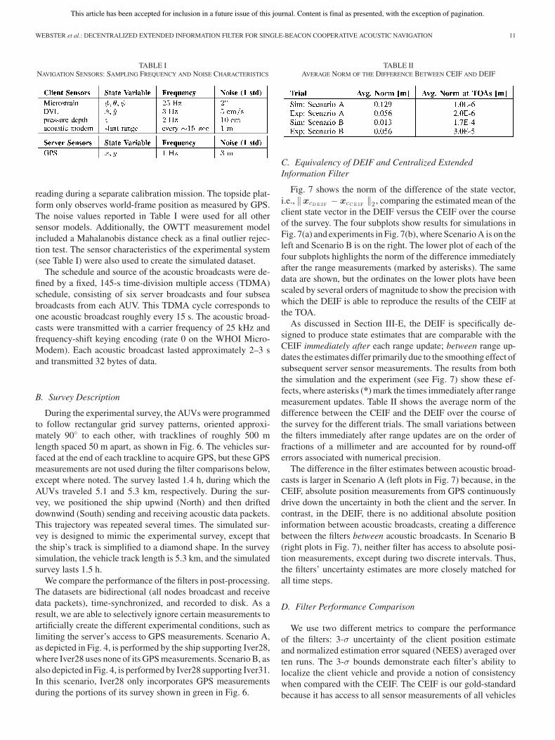
TABLE INAVIGATION SENSORS: SAMPLING FREQUENCY AND NOISE CHARACTERISTICS
reading during a separate calibration mission. The topside plat-form only observes world-frame position as measured by GPS.The noise values reported in Table I were used for all othersensor models. Additionally, the OWTT measurement modelincluded a Mahalanobis distance check as a final outlier rejec-tion test. The sensor characteristics of the experimental system(see Table I) were also used to create the simulated dataset.
The schedule and source of the acoustic broadcasts were de-fined by a fixed, 145-s time-division multiple access (TDMA)schedule, consisting of six server broadcasts and four subseabroadcasts from each AUV. This TDMA cycle corresponds toone acoustic broadcast roughly every 15 s. The acoustic broad-casts were transmitted with a carrier frequency of 25 kHz andfrequency-shift keying encoding (rate 0 on the WHOI Micro-Modem). Each acoustic broadcast lasted approximately 2–3 sand transmitted 32 bytes of data.
B. Survey Description
During the experimental survey, the AUVs were programmedto follow rectangular grid survey patterns, oriented approxi-mately 90◦ to each other, with tracklines of roughly 500 mlength spaced 50 m apart, as shown in Fig. 6. The vehicles sur-faced at the end of each trackline to acquire GPS, but these GPSmeasurements are not used during the filter comparisons below,except where noted. The survey lasted 1.4 h, during which theAUVs traveled 5.1 and 5.3 km, respectively. During the sur-vey, we positioned the ship upwind (North) and then drifteddownwind (South) sending and receiving acoustic data packets.This trajectory was repeated several times. The simulated sur-vey is designed to mimic the experimental survey, except thatthe ship’s track is simplified to a diamond shape. In the surveysimulation, the vehicle track length is 5.3 km, and the simulatedsurvey lasts 1.5 h.
We compare the performance of the filters in post-processing.The datasets are bidirectional (all nodes broadcast and receivedata packets), time-synchronized, and recorded to disk. As aresult, we are able to selectively ignore certain measurements toartificially create the different experimental conditions, such aslimiting the server’s access to GPS measurements. Scenario A,as depicted in Fig. 4, is performed by the ship supporting Iver28,where Iver28 uses none of its GPS measurements. Scenario B, asalso depicted in Fig. 4, is performed by Iver28 supporting Iver31.In this scenario, Iver28 only incorporates GPS measurementsduring the portions of its survey shown in green in Fig. 6.
TABLE IIAVERAGE NORM OF THE DIFFERENCE BETWEEN CEIF AND DEIF
C. Equivalency of DEIF and Centralized ExtendedInformation Filter
Fig. 7 shows the norm of the difference of the state vector,i.e., ‖xcD E IF − xcC E IF ‖2 , comparing the estimated mean of theclient state vector in the DEIF versus the CEIF over the courseof the survey. The four subplots show results for simulations inFig. 7(a) and experiments in Fig. 7(b), where Scenario A is on theleft and Scenario B is on the right. The lower plot of each of thefour subplots highlights the norm of the difference immediatelyafter the range measurements (marked by asterisks). The samedata are shown, but the ordinates on the lower plots have beenscaled by several orders of magnitude to show the precision withwhich the DEIF is able to reproduce the results of the CEIF atthe TOA.
As discussed in Section III-E, the DEIF is specifically de-signed to produce state estimates that are comparable with theCEIF immediately after each range update; between range up-dates the estimates differ primarily due to the smoothing effect ofsubsequent server sensor measurements. The results from boththe simulation and the experiment (see Fig. 7) show these ef-fects, where asterisks (*) mark the times immediately after rangemeasurement updates. Table II shows the average norm of thedifference between the CEIF and the DEIF over the course ofthe survey for the different trials. The small variations betweenthe filters immediately after range updates are on the order offractions of a millimeter and are accounted for by round-offerrors associated with numerical precision.
The difference in the filter estimates between acoustic broad-casts is larger in Scenario A (left plots in Fig. 7) because, in theCEIF, absolute position measurements from GPS continuouslydrive down the uncertainty in both the client and the server. Incontrast, in the DEIF, there is no additional absolute positioninformation between acoustic broadcasts, creating a differencebetween the filters between acoustic broadcasts. In Scenario B(right plots in Fig. 7), neither filter has access to absolute posi-tion measurements, except during two discrete intervals. Thus,the filters’ uncertainty estimates are more closely matched forall time steps.
D. Filter Performance Comparison
We use two different metrics to compare the performanceof the filters: 3-σ uncertainty of the client position estimateand normalized estimation error squared (NEES) averaged overten runs. The 3-σ bounds demonstrate each filter’s ability tolocalize the client vehicle and provide a notion of consistencywhen compared with the CEIF. The CEIF is our gold-standardbecause it has access to all sensor measurements of all vehicles
This article has been accepted for inclusion in a future issue of this journal. Content is final as presented, with the exception of pagination.
12 IEEE TRANSACTIONS ON ROBOTICS
Fig. 6. Trajectories of the topside platform (a ship) and two AUVs during our field experiment (a) and in the simulated dataset (b). Sections of Iver28’s trajectoryshown in green indicate where its GPS measurements were incorporated into the filters during operational Scenario B (Iver28 supporting Iver31).
Fig. 7. Norm of the difference in client state between DEIF and CEIF for simulations (a) and experiments (b). The left column in each subfigure representsScenario A (ship with continuous access to GPS supporting Iver28); the right column represents Scenario B (Iver28 with intermittent access to GPS supportingIver31). The lower plots in all subfigures provide a scaled view of the ordinate axis for visual clarity. Note that in all cases, the CEIF and DEIF are numericallyequivalent at the TOA.
This article has been accepted for inclusion in a future issue of this journal. Content is final as presented, with the exception of pagination.
WEBSTER et al.: DECENTRALIZED EXTENDED INFORMATION FILTER FOR SINGLE-BEACON COOPERATIVE ACOUSTIC NAVIGATION 13
Fig. 8. Simulation results for Scenario A (ship supporting Iver28) and Scenario B (Iver28 supporting Iver31) on the left and right, respectively. (a) Filterestimated uncertainty. The inset in Scenario B shows where the DEIF uncertainty estimate differs briefly from the CEIF during the time when GPS was available.(b) Correlation coefficient (absolute value) between the server and the client, as calculated by the CEIF. The development of significant correlation between theserver and the client is evident in Scenario B. (c) Ten-run average NEES. The horizontal black line indicates the one-sided χ2 95% confidence bound. Note thatthe displayed NEES are smoothed with a 1-min moving average filter for ease of visibility and comparison. The percentages in the legend represent the amount oftime the (nonsmoothed) NEES for each filter exceeds the 95% confidence bound.
and, therefore, should have the lowest valid uncertainty estimate.The NEES provides a true measure of filter consistency based onwhether the estimation errors of the filter are zero mean and havemagnitudes commensurate with the covariance of the filter [50].Because the NEES can only be calculated when the true state ofthe system is known, we calculate it for the simulated data only.The performance of the filters is summarized here and discussedin detail below for each filter.
Figs. 8 and 9 illustrate the results for all of the filters evaluated,using simulated and experimental data, respectively. Both casesshow similar trends. Subfigures (a) in both Figs. 8 and 9 showthe 3-σ uncertainty estimate for each of the filters evaluated.The DEIF has the lowest consistent uncertainty estimate andmost closely matches the CEIF in both scenarios. The EEKFshows the next smallest uncertainty estimate in Scenario A butproduces an overly optimistic uncertainty estimate in ScenarioB that is not consistent with the CEIF. The raw GPS method
produces an uncertainty estimate that is larger than the EEKFin Scenario A, and only a marginal improvement over DR inScenario B, because range measurements are only incorporatedwhen the server AUV has access to GPS measurements at thesurface. The IU algorithm produces an uncertainty estimate thatis the largest of the filters evaluated for Scenario A. The IU’suncertainty estimate shows an improvement over DR but isunbounded in time.
Subfigures (b) in both Figs. 8 and 9 show the absolute corre-lation coefficient between the server and the client in the CEIFover the course of the survey (Scenario A). The development ofsignificant correlation between the server and client is evidentin Scenario B. The EEKF’s inconsistent estimate results fromignoring this correlation (discussed below).
Fig. 8(c) compares the NEES for all filters against the 95%confidence bound. Note that the NEES for each filter has beensmoothed over a 1-min window for readability. None of the
This article has been accepted for inclusion in a future issue of this journal. Content is final as presented, with the exception of pagination.
14 IEEE TRANSACTIONS ON ROBOTICS
Fig. 9. Experimental results for Scenario A (ship supporting Iver28) and Scenario B (Iver28 supporting Iver31) on the left and right, respectively. (a) Filterestimated uncertainty. The inset in Scenario B shows where the DEIF uncertainty estimate differs briefly from the CEIF during the time when GPS was available.(b) Correlation coefficient (absolute value) between the server and the client, as calculated by the CEIF. The development of significant correlation between theserver and the client is evident in Scenario B.
filters deviate far from the 95% chi-squared bounds, except forthe EEKF, which clearly produces an inconsistent estimate inScenario B when significant correlation between the server andthe client exists. Spikes in the NEES are clearly visible in the IU,CEIF, and DEIF during vehicle turns at the end of the tracklines.These are caused by the constant-velocity, linear process modelnot accurately modeling turn dynamics. This, coupled with thereceipt of OWTTs measurements during turns (which drivesuncertainty down during the uncertain turn event), leads the filterto temporarily be more confident in its position than is accurate.
1) Decentralized Extended Information Filter Results: TheDEIF navigation estimate onboard the client vehicle matchesthe CEIF estimate within numerical precision at the TOA, asseen in Fig. 7, for both simulated and experimental scenarios. InScenario B, Iver31’s uncertainty estimate differs briefly from theCEIF during the time when GPS was available, as shown in theinsets of Figs. 8 and 9. Once surfaced, Iver28 receives severalGPS measurements, which immediately drive the uncertaintydown for both vehicles in the CEIF; however, it is not until thenext acoustic broadcast from the server vehicle (Iver28) that theclient platform’s DEIF (Iver31) is able to incorporate the deltainformation with GPS and fully match the CEIF. The CEIF andDEIF are identical immediately after each range measurementsbut differ between broadcasts for as long as Iver28 is receiv-ing GPS measurements. Note that in the simulated survey [seeFig. 8(a)], the difference between the DEIF and the CEIF occursacross multiple acoustic broadcasts; this is because the simula-tion does not prevent acoustic broadcasts during the receipt ofGPS measurements.
2) Egocentric Extended Kalman Filter Results: The EEKFuncertainty estimate closely matches the CEIF in Scenario A
when the correlation between the server and the client is small.However, in Scenario B, both the simulation and experimentclearly show that the EEKF fails to produce an estimate consis-tent with the CEIF. This is a result of the large correlation thatpersists between each vehicle’s position estimate causing theclient vehicle’s EEKF to double-count successive range mea-surements, as described in Section IV-B. Relative range mea-surements create large correlation between vehicles. Conversely,absolute position observations tend to destroy correlation be-tween previously correlated vehicles, which is why the EEKFuncertainty estimate more closely matches the CEIF in Sce-nario A. (See [13, App.] for a simplified example illustratingthis effect due to GPS.) The NEES computed in simulationfrom Scenario B clearly demonstrates the inconsistency of thisfilter in situations where vehicle estimates are highly correlated.
3) Raw Global Positioning System Results: The raw GPSmethod in Scenario A results in a bounded-error positionestimate, with 3-σ uncertainty closer to the CEIF than the IUalgorithm, in both the simulation and the experiment. InScenario B, this method is an improvement over DR, butnot significantly because the server vehicle only sends rangepackets during two short intervals when GPS is available. Notethat results from this method are not shown for the experimentaltrial of Scenario B in Fig. 4 because the transducer on theAUV is above the waterline when the vehicle is at the surfacereceiving GPS, and is, therefore, unable to transmit rangepackets. The drawbacks to this method are that it cannotachieve the lowest uncertainty estimate without filtering topsidemeasurements (as with the CEIF) and that the server musthave had recent access to a GPS fix in order to execute a rangemeasurement. However, this algorithm is trivially robust to
This article has been accepted for inclusion in a future issue of this journal. Content is final as presented, with the exception of pagination.
WEBSTER et al.: DECENTRALIZED EXTENDED INFORMATION FILTER FOR SINGLE-BEACON COOPERATIVE ACOUSTIC NAVIGATION 15
TABLE IIIOPERATIONAL PACKET LOSS STATISTICS
packet loss or failure of the server node, and the client is ableto incorporate measurements from several independent serverswithout modification and arrive at a consistent estimate.
4) Interleaved Update Algorithm Results: The IU algorithmshows improvement over dead-reckoning with an uncertaintyestimate that is guaranteed to be consistent, as shown by itsNEES. However, the filter’s estimate exhibits unbounded growthin uncertainty over time. As mentioned in Section IV-B3, thisis expected for a two-vehicle topology with unidirectional com-munication.
VI. DISCUSSION
In this section, we discuss several topics related to the opera-tional implementation of the DEIF: packet loss, filter telemetryrequirements, and when linear process models are required. Wealso discuss possible (nonoptimal) extensions of the DEIF ap-proach described herein to multi-vehicle topologies.
A. Packet Loss
The DEIF approach described herein relies on the sequentialbroadcast and receipt of delta information packets. In prac-tice, the nonlossy communication assumption cannot be met,as packets are routinely lost to an often faulty acoustic com-munication channel, making packet loss an operational concernfor real-time implementation. In the experimental dataset usedin this study, only successful acoustic broadcasts were used inpost-processing to run the filter. Table III tabulates the packetloss statistics for each of the different communication paths.The two entries in bold represent the communication paths usedto run the DEIF experiments reported here.
A number of possible solutions exist to address the issueof packet loss when implementing the DEIF in real time foruse in the field. We describe several proposed methods below:1) sending redundant information, 2) utilizing acknowledgmentsfrom the client platform, and 3) an alternative formulation of thedelta information packet. In practice, we expect these and othersolutions to be developed and refined over time as this algorithmmatures and is used in the field.
1) Redundant Information Packets: Our first safeguardagainst dropped acoustic packets is to broadcast redundant infor-mation. A delta information message describes a transition of theserver state between consecutive TOLs, in particular, the deltainformation at the nth TOL relates the server state from timeTOLn−1 to time TOLn , abbreviated ΔsTOLn −1 :n
. Since we cannotrely on the client receiving every packet, we require the serverto broadcast delta packets corresponding to transitions from thelast k TOLs to the current TOL: ΔsTOLn −1 :n
, . . . ,ΔsTOLn −k :n.
In this case, the server easily computes the delta packets, asin (23) and (24), for each delta relation by marginalizing outintermediate states. For example, the server vehicle tracks state
xsk=
[x�
sk, x�
sTOLn, . . . , x�
sTOLn −k
]�.
To compute the delta packet corresponding to the transitionΔsTOLn −k :n
, we simply marginalize out states corresponding toTOLn−1 , . . . ,TOLn−k+1 and calculate the delta information asper usual.
2) Client Acknowledgment: In practice, subsea vehicles typ-ically send some minimal acoustic state data to report generalmission health. We propose to encode the last server TOL statereceived, which is denoted TOL� , into each client state packetsent to the server. Under this scheme, in addition to the standardone-step delta information packet, i.e., ΔsTOLn −1 :n
, the serverwould also broadcast the delta information relative to the lastknown good TOL, i.e., ΔsTOL� :n
. This approach allows for theclient vehicle to resume normal usage should it ever miss aregular one-step packet.
3) Alternate Packet Composition: Recently, Walls andEustice [55] proposed an alternate packet formulation, dubbedthe origin-state method, which allows the client vehicle toreconstruct the server information matrix in a way that is robustto packet loss. While this approach solves a different problemthan the DEIF, the authors of [55] have applied their algorithmto a modified DEIF implementation and have shown it to berobust to a lossy acoustic channel, subject to certain operationalrestrictions.
B. Filter Telemetry Requirements
Because of the severe constraints imposed on data packetsize by the limited capacity of the acoustic channel, we includea brief discussion of the telemetry requirements for the differentalgorithms compared in this paper. The amount of data that canbe transmitted in an acoustic data packet depend on the car-rier frequency, bandwidth, and encoding method of the signal,as well as the characteristics of the local sound channel [11].Currently, the WHOI Micro-Modem supports data rates rangingfrom a single 32-byte frame per packet (rate 0, encoded withfrequency shift keying) to eight 256-byte frames per packet (rate5, encoded with phase-shift keying) [5]. Assuming one broad-cast every 15 s, the resulting maximum throughput varies from128 bytes/min to 8 kb/min. The experiments, as described inSection V-A, used rate 0.
The relative data packet size demanded by each filter is sum-marized in Table IV for a server–client network topology. Weplace a small overhead on each broadcast by including depthinformation because we project range measurements into thelocal-level plane. Both the EEKF and IU only require that lo-cal state and covariance corresponding to x, y position be en-coded, since each measurement is considered independent, andthe client filter only needs access to elements of the state in-volved in the measurement update. Therefore, taking advantageof symmetry, the EEKF and IU require transmitting two floatsfor mean and three for covariance in the acoustic broadcast.Note that the telemetry requirements for IU implemented in
This article has been accepted for inclusion in a future issue of this journal. Content is final as presented, with the exception of pagination.
16 IEEE TRANSACTIONS ON ROBOTICS
TABLE IVTELEMETRY PAYLOAD REQUIREMENTS FOR A SERVER–CLIENT TOPOLOGY
an n-vehicle network with bidirectional communication growswithO(n2). If the uncertainty of the GPS measurement is knownby the vehicle beforehand (a reasonable assumption), only twofloats for the x, y GPS position must be transmitted by the acous-tic broadcast in the raw GPS method. Delta state in the DEIF iscomputed between the last TOL augmented state and the currentstate; therefore, the DEIF requires eight floats (2 × 4 for statedimension four) for the delta information vector and 36 for thedelta information matrix in each data packet.
The DEIF∗ in the table refers to a DEIF in which the serverstate contains only world-frame x, y position, further reduc-ing the state model. In this case, the process model follows anodometry-driven control input (e.g., integrated velocity mea-surements) and white-noise. This implementation is the subjectof current research, and preliminary results, which are currentlyunder review, show that it achieves a far lower telemetry payloadat the cost of a less confident estimate.
C. Linear Process Models
As noted in Section III-F, the client process model is not re-quired to be linear, but the server process model and observationmodels must be linear for the DEIF to identically reproduce theresults of the CEIF. For the implementation of the DEIF de-scribed herein, we employ a linear process model for the clientas well as the server for several reasons. For DOFs that arewell instrumented, compared with the actual system dynamics,a common simplification of the process model is to excludethose well-instrumented states from the set of estimated states.For the AUVs used in this experiment, and many AUVs on themarket, attitude and depth are well instrumented compared withthe dynamics of the vehicle [56]. In addition, Webster et al. [12]verified that the majority of the uncertainty resides in x, y po-sition elements of the client state vector. Therefore, the use oflinear models for the client is a reasonable assumption.
A simplified process model for the server, in the case wherethe server is a ship, is justified by the server’s continuous accessto GPS measurements. In addition, the simplified server processmodel reduces the amount of data required to broadcast state in-formation from the server to the client, an important operationalconcern given the limited capacity of the underwater acousticchannel [28]. Extending the DEIF framework to accommodatea nonlinear server, while continuing to ensure identical resultsbetween the CEIF and DEIF, would require that the client trans-mit a new linearization point to the server following a rangemeasurement update.
Fig. 10. Two multi-vehicle topologies that are simple (suboptimal) extensionsof the DEIF: (a) the multi-client topology where a single server supports multipleclients and (b) the cascaded network topology where clients also perform asservers.
D. Multi-vehicle Topologies
Two suboptimal multi-vehicle estimation topologies that aresimple extensions of the DEIF are shown in Fig. 10. The first is amulti-client topology, in which a single server supports multipleclients. The second is a cascaded topology, in which the server–client model described in this paper is extended such that theclient supports one or more additional subsea clients.
Extending the two-vehicle DEIF presented in this paper toeither multi-vehicle topology is trivial. In the multi-client topol-ogy shown in Fig. 10(a), the server performs a single acousticbroadcast, and each client runs its own independent DEIF withno knowledge of the other clients. This is scalable to as many ve-hicles as can operate within acoustic range of the server. Note,however, that in this case, the DEIF does not reproduce thedistribution produced by a single global CEIF that tracks cor-relation between all vehicles. Instead, each DEIF is equivalentto a corresponding two-vehicle CEIF that tracks only the serverand an individual client.
In the serially connected network topology shown inFig. 10(b), unidirectional communication of position informa-tion is a simple, cascaded implementation of two DEIFs. Notethat clients at the end of a serially connected network will haveaccess to all range information in the system and will be ableto exactly reproduce the results of the CEIF. However, interme-diate clients will not, and, therefore, will not be able to exactlyreproduce the results of the CEIF.
The performance of the DEIF compared with other algorithmspresented in the literature has been investigated by Walls andEustice [13] for these topologies using experimental data froma three-node network. Packet loss, as noted in Section VI-A,remains an operational concern for both of these extensions.
VII. CONCLUSION AND FUTURE WORK
This paper has presented a detailed derivation of the DEIF al-gorithm for the synchronous-clock acoustic navigation of a sin-gle subsea client vehicle. We showed analytically that the DEIFexactly reproduces the estimate of the corresponding server–client CEIF at the TOA. Simulation and experimental trials val-idated the effectiveness of the DEIF at consistently localizingthe client vehicle, as well as reproducing the CEIF. A compar-ative analysis demonstrated the performance of the DEIF andseveral previously reported approaches to cooperative acousticnavigation. Additionally, we showed that the DEIF performs fa-vorably when compared with previously reported decentralizedacoustic cooperative localization algorithms.
This article has been accepted for inclusion in a future issue of this journal. Content is final as presented, with the exception of pagination.
WEBSTER et al.: DECENTRALIZED EXTENDED INFORMATION FILTER FOR SINGLE-BEACON COOPERATIVE ACOUSTIC NAVIGATION 17
While the DEIF achieves excellent theoretical results, a real-time implementation requires additional overhead to addresspacket loss, as described in Section VI. Current on-going workcontinues to investigate more robust information descriptionsthat can handle dropped acoustic transmissions, such as thepreliminary work reported in [55]. Furthermore, we seek analgorithm that can scale to larger networks and share informa-tion bidirectionally to accommodate many AUVs operating oververy large operational areas.
REFERENCES
[1] R. M. Eustice, L. L. Whitcomb, H. Singh, and M. Grund, “Recent ad-vances in synchronous-clock one-way-travel-time acoustic navigation,”in Proc. IEEE/MTS OCEANS Conf. Exhib., Boston, MA, USA, Sep. 2006,pp. 1–6.
[2] R. M. Eustice, H. Singh, and L. L. Whitcomb, “Synchronous-clock one-way-travel-time acoustic navigation for underwater vehicles,” J. FieldRobot., vol. 28, no. 1, pp. 121–136, 2011.
[3] M. Hunt, W. Marquet, D. Moller, K. Peal, W. Smith, and R. Spindel, “Anacoustic navigation system,” Woods Hole Ocean. Inst., Woods Hole, MA,USA, Tech. Rep. WHOI-74-6, Dec. 1974.
[5] L. Freitag, M. Grund, S. Singh, J. Partan, P. Koski, and K. Ball, “TheWHOI micro-modem: An acoustic communications and navigation sys-tem for multiple platforms,” in Proc. IEEE/MTS OCEANS Conf. Exhib.,Washington, DC, USA, Sep. 2005, pp. 1086–1092.
[6] L. Freitag, M. Grund, J. Partan, K. Ball, S. Singh, and P. Koski, “Multi-band acoustic modem for the communications and navigation aid AUV,”in Proc. IEEE/MTS OCEANS Conf. Exhib., Washington, DC, USA, Sep.2005, pp. 1080–1085.
[7] R. M. Eustice, L. L. Whitcomb, H. Singh, and M. Grund, “Experimentalresults in synchronous-clock one-way-travel-time acoustic navigation forautonomous underwater vehicles,” in Proc. IEEE Int. Conf. Robot. Autom.,Rome, Italy, Apr. 2007, pp. 4257–4264.
[8] S. E. Webster, R. M. Eustice, H. Singh, and L. L. Whitcomb, “Advancesin single-beacon one-way-travel-time acoustic navigation for underwatervehicles,” Int. J. Robot. Res., no. 8, pp. 935–950, Jul. 2012.
[9] S. E. Webster, R. M. Eustice, H. Singh, and L. L. Whitcomb, “Preliminarydeep water results in single-beacon one-way-travel-time acoustic naviga-tion for underwater vehicles,” in Proc. IEEE/RSJ Int. Conf. Intell. Robot.Syst., St. Louis, MO, USA, Oct. 2009, pp. 2053–2060.
[10] D. Kilfoyle and A. Baggeroer, “The state of the art in underwater acoustictelemetry,” IEEE J. Ocean. Eng., vol. 25, no. 1, pp. 4–27, Jan. 2000.
[11] S. Singh, S. E. Webster, L. Freitag, L. L. Whitcomb, K. Ball, J. Bailey, andC. Taylor, “Acoustic communication performance of the WHOI Micro-Modem in sea trials of the Nereus vehicle to 11,000 m depth,” in Proc.IEEE/MTS OCEANS Conf. Exhib., Biloxi, MS, USA, Oct. 2009, pp. 1–6.
[12] S. E. Webster, L. L. Whitcomb, and R. M. Eustice, “Preliminary resultsin decentralized estimation for single-beacon acoustic underwater naviga-tion,” in Proc. Robot. Sci. Syst. Conf., Zaragoza, Spain, Jun. 2010.
[13] J. M. Walls and R. M. Eustice, “Experimental comparison of synchronous-clock cooperative acoustic navigation algorithms,” in Proc. IEEE/MTSOCEANS Conf. Exhib., Kona, HI, USA, Sep. 2011, pp. 1–7.
[14] H. Mu, T. Bailey, P. Thompson, and H. Durrant-Whyte, “Decentralisedsolutions to the cooperative multi-platform navigation problem,” IEEETrans. Aerosp. Electron. Syst., vol. 47, no. 2, pp. 1433–1449, Apr. 2011.
[15] T. Song, “Observability of target tracking with range-only measurements,”IEEE J. Ocean. Eng., vol. 24, no. 24, pp. 383–387, Jul. 1999.
[16] A. Gadre and D. Stilwell, “A complete solution to underwater naviga-tion in the presence of unknown currents based on range measurementsfrom a single location,” in Proc. IEEE/RSJ Int. Conf. Intell. Robot. Syst.,Edmonton, AB, Canada, Aug. 2005, pp. 1420–1425.
[17] X. Zhou and S. Roumeliotis, “Robot-to-robot relative pose estimation fromrange measurements,” IEEE Trans. Robot., vol. 24, no. 6, pp. 1379–1393,Dec. 2008.
[18] M. F. Fallon, G. Papadopoulos, J. J. Leonard, and N. M. Patrikalakis, “Co-operative AUV navigation using a single maneuvering surface craft,” Int.J. Robot. Res., vol. 29, no. 12, pp. 1461–1474, Oct. 2010.
[19] A. Scherbatyuk, “The AUV positioning using ranges from one transponderLBL,” in Proc. IEEE/MTS OCEANS Conf. Exhib., San Diego, CA, USA,Oct. 1995, vol. 4, pp. 1620–1623.
[20] P. Baccou and B. Jouvencel, “Homing and navigation using one transpon-der for AUV, postprocessing comparisons results with long base-line nav-igation,” in Proc. IEEE Int. Conf. Robot. Autom., Washington, DC, USA,May 2002, vol. 4, pp. 4004–4009.
[21] M. B. Larsen, “Autonomous navigation of underwater vehicles,” Ph.D.dissertation, Tech. Univ. Denmark, Kongens Lyngby, Denmark, Feb. 2001.
[22] S. McPhail and M. Pebody, “Range-only positioning of a deep-divingautonomous underwater vehicle from a surface ship,” IEEE J. Ocean.Eng., vol. 34, no. 4, pp. 669–677, Oct. 2009.
[23] C. P. Morice and S. M. Veres, “Geometric bounding techniques for under-water localization using range-only sensors,” Proc. Inst. Mech. Eng. PartI: J. Syst. Contr. Eng., vol. 225, no. 1, pp. 74–84, 2011.
[24] S. Roumeliotis and G. Bekey, “Distributed multirobot localization,” IEEETrans. Robot. Autom., vol. 18, no. 5, pp. 781–795, Oct. 2002.
[25] A. Howard, “Multi-robot simultaneous localization and mapping usingparticle filters,” Int. J. Robot. Res., vol. 25, no. 12, pp. 1243–1256,2006.
[26] B. Kim, M. Kaess, L. Fletcher, J. Leonard, A. Bachrach, N. Roy, andS. Teller, “Multiple relative pose graphs for robust cooperative mapping,”in Proc. IEEE Int. Conf. Robot. Autom., May 2010, pp. 3185–3192.
[27] V. Indelman, P. Gurfil, E. Rivlin, and H. Rotstein, “Graph-based distributedcooperative navigation,” in Proc. IEEE Int. Conf. Robot. Autom., May2011, pp. 4786–4791.
[28] J. Partan, J. Kurose, and B. N. Levine, “A survey of practical issues in un-derwater networks,” SIGMOBILE Mob. Comput. Commun. Rev., vol. 11,pp. 23–33, Oct. 2007.
[29] A. Ribeiro, G. B. Giannakis, and S. I. Roumeliotis, “SOI-KF: DistributedKalman filtering with low-cost communications using the sign of innova-tions,” IEEE Trans. Signal Process., vol. 54, no. 12, pp. 4782–4795, Dec.2006.
[30] E. D. Nerurkar, K. X. Zhou, and S. I. Roumeliotis, “Hybrid estimationframework for multi-robot cooperative localization using quantized mea-surements,” Res. Note, Dept. Comput. Sci. Eng., Univ. Minnesota, Min-neapolis, MN, USA, 2011.
[31] T. Bailey, M. Bryson, H. Mu, J. Vial, L. McCalman, and H. Durrant-Whyte, “Decentralised cooperative localisation for heterogeneous teamsof mobile robots,” in Proc. IEEE Int. Conf. Robot. Autom., May 2011,pp. 2859–2865.
[32] T. Bailey and H. Durrant-Whyte, “Decentralised data fusion with delayedstates for consistent inference in mobile ad hoc networks,” AustralianCentre for Field Robotics, Univ. Sydney, Sydney, N.S.W., Australia,Tech. Rep., 2007. (see http://www-personal.acfr.usyd.edu.au/tbailey/techreports/index.html)
[33] R. Aragues, J. Cortes, and C. Sagues, “Distributed consensus on robot net-works for dynamically merging feature-based maps,” IEEE Trans. Robot.,vol. 28, no. 4, pp. 840–854, Aug. 2012.
[34] D. Maczka, A. Gadre, and D. Stilwell, “Implementation of a cooperativenavigation algorithm on a platoon of autonomous underwater vehicles,”in Proc. IEEE/MTS OCEANS Conf. Exhib., Vancouver, BC, Canada, Oct.2007, pp. 1–6.
[35] A. Bahr, M. Walter, and J. Leonard, “Consistent cooperative localization,”in Proc. IEEE Int. Conf. Robot. Autom., Kobe, Japan, May 2009, pp. 3415–3422.
[36] A. Bahr, J. J. Leonard, and M. F. Fallon, “Cooperative localization forautonomous underwater vehicles,” Int. J. Robot. Res., vol. 28, no. 6,pp. 714–728, Jun. 2009.
[37] J. Vaganay, J. Leonard, J. Curcio, and J. Willcox, “Experimental validationof the moving long base-line navigation concept,” in Proc. IEEE/OESAutonom. Underwater Veh., Jun. 2004, pp. 59–65.
[38] M. F. Fallon, G. Papadopoulos, and J. J. Leonard, “Cooperative AUVnavigation using a single surface craft,” in Proc. Field Service Robot.,Cambridge, MA, USA, Jul. 2009, pp. 1–10.
[39] M. Fallon, G. Papadopoulos, and J. Leonard, “A measurement distributionframework for cooperative navigation using multiple AUVs,” in Proc.IEEE Int. Conf. Robot. Autom., May 2010, pp. 4256–4263.
[40] A. G. O. Mutambara, Decentralized Estimation and Control for Multisen-sor Systems. Boca Raton, FL, USA: CRC, 1998.
[41] M. Bozorg, E. Nebot, and H. Durrant-Whyte, “A decentralised navigationarchitecture,” in Proc. IEEE Int. Conf. Robot. Autom., May 1998, vol. 4,pp. 3413–3418.
[42] S. Thrun and Y. Liu, “Multi-robot SLAM with sparse extended infor-mation filers,” in Robotics Research, (ser. Springer Tracts in Advanced
This article has been accepted for inclusion in a future issue of this journal. Content is final as presented, with the exception of pagination.
18 IEEE TRANSACTIONS ON ROBOTICS
Robotics), P. Dario and R. Chatila, Eds. Berlin, Heidelberg, Germany:Springer-Verlag, 2005, vol. 15, pp. 254–266.
[43] S. Reece and S. Roberts, “Robust, low-bandwidth, multi-vehicle map-ping,” in Proc. Int. Conf. Inf. Fusion, Jul. 2005, vol. 2, pp. 1319–1326.
[44] S. Grime, H. F. Durrant-Whyte, and P. Ho, “Communication in decen-tralized data-fusion systems,” in Proc. Amer. Control Conf., Jun. 1992,pp. 3299–3303.
[45] R. M. Eustice, H. Singh, and J. J. Leonard, “Exactly sparse delayed-state filters for view-based SLAM,” IEEE Trans. Robot., vol. 22, no. 6,pp. 1100–1114, Dec. 2006.
[46] J. Diosdado and I. Ruiz, “Decentralised simultaneous localisation andmapping for AUVs,” in Proc. IEEE OCEANS Eur. Conf. Exhib., Jun.2007, pp. 1–6.
[47] F. Dellaert and M. Kaess, “Square root SAM: Simultaneous localizationand mapping via square root information smoothing,” Int. J. Robot. Res.,vol. 25, no. 12, pp. 1181–1204, Dec. 2006.
[48] M. Kaess, A. Ranganathan, and F. Dellaert, “iSAM: Incremental smooth-ing and mapping,” IEEE Trans. Robot., vol. 24, no. 6, pp. 1365–1378,Dec. 2008.
[49] M. Fallon, M. Kaess, H. Johannsson, and J. Leonard, “Efficient AUVnavigation fusing acoustic ranging and side-scan sonar,” in Proc. IEEEInt. Conf. Robot. Autom., Shanghai, China, May 2011, pp. 2398–2405.
[50] Y. Bar-Shalom, X. R. Li, and T. Kirubarajan, Estimation With Applicationsto Tracking and Navigation. New York, NY, USA: Wiley, 2001.
[51] S. E. Webster, R. M. Eustice, C. Murphy, H. Singh, and L. L. Whitcomb,“Toward a platform-independent acoustic communications and navigationsystem for underwater vehicles,” in Proc. IEEE/MTS OCEANS Conf.Exhib., Biloxi, MS, USA, Oct. 2009, pp. 1–7.
[52] D. A. Smallwood and L. L. Whitcomb, “Model-based dynamic position-ing of underwater robotic vehicles: Theory and experiment,” IEEE J.Ocean. Eng., vol. 29, no. 1, pp. 169–186, Jan. 2004.
[53] L. L. Whitcomb, D. R. Yoerger, H. Singh, and J. Howland, “Advancesin underwater robot vehicles for deep ocean exploration: navigation, con-trol, and survey operations,” in Robotics Research: The Ninth Interna-tional Symposium, J. Hollerbach and D. Koditschek, Eds. London, U.K.:Springer-Verlag, 1999, ch. 13, pp. 439–448.
[54] H. Brown, A. Kim, and R. Eustice, “Development of a multi-AUV SLAMtestbed at the University of Michigan,” in Proc. IEEE/MTS OCEANS Conf.Exhib., Quebec City, QC, Canada, Sep. 2008, pp. 1–6.
[55] J. M. Walls and R. M. Eustice, “An origin state method for lossysynchronous-clock acoustic navigation,” in Proc. IFAC Workshop Nav-igat. Guidance Control Underwater Veh., Porto, Portugal, Apr. 2012.
[56] J. C. Kinsey, R. M. Eustice, and L. L. Whitcomb, “A survey of underwatervehicle navigation: Recent advances and new challenges,” in Proc. IFACConf. Manoeuvr. Control Marine Craft, Lisbon, Portugal, Sep. 2006.
Sarah E. Webster (S’08–M’12) received the B.S.degree in mechanical engineering from the Mas-sachusetts Institute of Technology, Cambridge, MA,USA, in 2000 and the Ph.D. degree in mechanicalengineering from the Johns Hopkins University, Bal-timore, MD, USA, in 2010.
She is currently a postdoctoral scholar with theOcean Physics Department, Applied Physics Labo-ratory, University of Washington, Seattle, WA, USA.Her research interests include navigation for au-tonomous underwater vehicles, decentralized estima-
tion, and long-term autonomy.
Jeffrey M. Walls (S’11) received the B.S. degree inmechanical engineering from the University of Vir-ginia, Charlottesville, VA, USA, in 2009 and the M.S.degree in mechanical engineering from the Univer-sity of Michigan, Ann Arbor, MI, USA, in 2011.Currently, he is pursuing the Ph.D. degree with theDepartment of Mechanical Engineering, Universityof Michigan.
His research interest are in the areas of cooperativenavigation and coordinated planning for autonomousunderwater vehicles.
Louis L. Whitcomb (S’86–M’95–SM’02–F’11) re-ceived the Ph.D. degree in electrical engineering fromYale University, New Haven, CT, USA, in 1992.
He is currently a Professor with the Departmentof Mechanical Engineering, with secondary appoint-ment in the Department of Computer Science, theJohns Hopkins University, Baltimore, MD, USA,where he is the Director of the Laboratory for Compu-tational Sensing and Robotics. His research interestsinclude the design, dynamics, and control of roboticsystems.
Dr. Whitcomb is the Louis R. Sardella Faculty Scholar with the G.W.C.Whiting School of Engineering, The Johns Hopkins University.
Ryan M. Eustice (S’00–M’05–SM’10) received theB.S. degree in mechanical engineering from Michi-gan State University, East Lansing, MI, USA, in 1998and the Ph.D. degree in ocean engineering from theMassachusetts Institute of Technology/Woods HoleOceanographic Institution Joint Program, WoodsHole, MA, USA, in 2005.
Currently, he is an Assistant Professor with theDepartment of Naval Architecture and Marine En-gineering, University of Michigan, Ann Arbor, MI,USA, with joint appointments in the Department of
Electrical Engineering and Computer Science and in the Department of Me-chanical Engineering. His research interests include autonomous navigationand mapping, computer vision and image processing, mobile robotics, and au-tonomous underwater vehicles.