IEEE TRANSACTIONS ON ROBOTICS, VOL. XX, NO. Y, MONTH 2005 1 A Fingerprint Pointing Device Utilizing the Deformation of the Fingertip during the Incipient Slip Yuichi Kurita, Atsutoshi Ikeda, Jun Ueda, and Tsukasa Ogasawara, Member, IEEE Abstract—In this paper, a novel pointing device is proposed that utilizes the deformation of the fingertip. When a fingertip is pressed and slightly slid on a rigid plate, a partial slip, called an “incipient slip”, occurs on the contact surface. While the deformation around the center of the contact area is small during the incipient slip, the boundary region moves to the sliding direction of the fingertip. The deformation changes depending on the sliding distance of the fingertip and the exerted force on the contact surface. The velocity of the pointer can be determined by the estimated distance and force based on the measurement of the deformation. In this study, the correlation between the sliding distance of the fingertip and the deformation, and between the exerted force and the deformation are investigated. The degree of the deformation due to the sliding motion can be estimated based on the detected fingerprint center. The Group Delay Spectrum (GDS) tracking method is proposed for the detection of the fingerprint center. A prototype pointing device is developed to evaluate the operationality of the proposed device. Comparative experiments with conventional pointing devices are conducted. The validity of the proposed device is confirmed by the experiments. Index Terms— Pointing device, fingerprint deformation, incip- ient slip, group delay spectrum I. I NTRODUCTION I MPROVEMENT in hardware technology allows the con- tinued miniaturization of computer hardwares. Likewise, the performance of PDAs (Personal Digital Assistants) and mobile phones have also improved year by year. To operate these compact information devices, input devices should be small and easy to use. Conventional pointing devices, however, such as computer mice, slide pads, and track points, have dis- advantages in operationality because of their size for portable devices. On the one hand, a number of man-machine interface systems have been proposed using human’s eye motions[1], [2], gesture recognition of an operator’s hands and fingers[3], Manuscript received January 20, 2002; revised November 18, 2002. This work was supported in part by 21st Century COE Program “Ubiquitous Networked Media Computing” and in part by a Grant-in-Aid for Scientific Research B(2) (No. 13450104), MEXT, Japan. Yuichi Kurita is with the Graduate School of Engineering, Hiroshima University, 1-4-1 Kagamiyama, Higashi-Hiroshima, Hiroshima, 739-0045, Japan (E-mail: kurita@hfl.hiroshima-u.ac.jp). Atsutoshi Ikeda is with Yamaha Motor Co., Ltd., 2500 Shingai, Iwata, Shizuoka, Japan. Jun Ueda and Tsukasa Ogasawara are with the Graduate School of Infor- mation Science, Nara Institute of Science and Technology (NAIST), 8916- 5 Takayama, Ikoma, Nara, 630-0192, Japan (E-mail: [email protected], [email protected]). [4], and other features[5], [6], [7]. These vision-based in- terfaces have advantages in that the operator’s motions can be measured without any attachments to his/her body. On the other hand, wearable measuring systems have also been proposed such as wearable gloves[8], [9], rings[10], or special devices attached on the arm[11] and nails[12]. However, these complex systems are not suitable for portable devices. In order to develop a novel pointing device that has good operationality, occupies a small space, and is low in cost, we propose to use the deformation of the fingertip during the incipient slip. An operator presses the fingertip and slightly slides it over the surface of the fingerprint-capturing device. During such motion, a partial slip occurs on the contact surface before the finger completely slips relative to the sur- face. This phenomenon, called “incipient slip” occurs because the pressure is smaller around the boundary of the contact region than around the center[13], [14]. By measuring and analyzing the incipient slip, the movement of the fingertip can be estimated even in the slight sliding motion of the fingertip. Since the gross slip is unnecessary for the operation of the pointer, operators can control the pointing device with a minimum fingertip motion. In addition, a click action can also be detected by measuring the area of the contact region, which expands as the strength of the pressure increases. Fingerprint images can be used for a fingerprint verification. Therefore, the fingerprint capturing device can be shared with the proposed pointing device. The proposed pointing device can be miniaturized since very small and thin fingerprint capturing devices have been developed. In this paper, the characteristics of the fingertip deformation is quantitatively investigated. Based on the investigation, a novel operational method for pointing devices that use the deformation of the fingertip is proposed. Additionally, a pro- totype device is developed to evaluate the operationality of the proposed method. II. FINGERTIP DEFORMATION DURING I NCIPIENT SLIP A. Incipient Slip A human’s fingertip roughly consists of a bone, subcuta- neous tissue, and skin. When a fingertip is pressed and slid on a rigid plate, the deformation of the fingertip can be assumed as the deformation of an elastic sphere. Since the pressure around the boundary of the contact region is smaller than the pressure of the center, the slip between the sphere and the plate occurs in the boundary region. If the entire contact
Transcript
IEEE TRANSACTIONS ON ROBOTICS, VOL. XX, NO. Y, MONTH 2005 1
A Fingerprint Pointing DeviceUtilizing the Deformation of the Fingertip
during the Incipient SlipYuichi Kurita, Atsutoshi Ikeda, Jun Ueda, and Tsukasa Ogasawara, Member, IEEE
Abstract— In this paper, a novel pointing device is proposedthat utilizes the deformation of the fingertip. When a fingertipis pressed and slightly slid on a rigid plate, a partial slip, calledan “incipient slip”, occurs on the contact surface. While thedeformation around the center of the contact area is small duringthe incipient slip, the boundary region moves to the slidingdirection of the fingertip. The deformation changes dependingon the sliding distance of the fingertip and the exerted force onthe contact surface. The velocity of the pointer can be determinedby the estimated distance and force based on the measurementof the deformation.
In this study, the correlation between the sliding distance of thefingertip and the deformation, and between the exerted force andthe deformation are investigated. The degree of the deformationdue to the sliding motion can be estimated based on thedetected fingerprint center. The Group Delay Spectrum (GDS)tracking method is proposed for the detection of the fingerprintcenter. A prototype pointing device is developed to evaluate theoperationality of the proposed device. Comparative experimentswith conventional pointing devices are conducted. The validityof the proposed device is confirmed by the experiments.
Index Terms— Pointing device, fingerprint deformation, incip-ient slip, group delay spectrum
I. INTRODUCTION
IMPROVEMENT in hardware technology allows the con-tinued miniaturization of computer hardwares. Likewise,
the performance of PDAs (Personal Digital Assistants) andmobile phones have also improved year by year. To operatethese compact information devices, input devices should besmall and easy to use. Conventional pointing devices, however,such as computer mice, slide pads, and track points, have dis-advantages in operationality because of their size for portabledevices.
On the one hand, a number of man-machine interfacesystems have been proposed using human’s eye motions[1],[2], gesture recognition of an operator’s hands and fingers[3],
Manuscript received January 20, 2002; revised November 18, 2002. Thiswork was supported in part by 21st Century COE Program “UbiquitousNetworked Media Computing” and in part by a Grant-in-Aid for ScientificResearch B(2) (No. 13450104), MEXT, Japan.
Yuichi Kurita is with the Graduate School of Engineering, HiroshimaUniversity, 1-4-1 Kagamiyama, Higashi-Hiroshima, Hiroshima, 739-0045,Japan (E-mail: [email protected]).
Atsutoshi Ikeda is with Yamaha Motor Co., Ltd., 2500 Shingai, Iwata,Shizuoka, Japan.
Jun Ueda and Tsukasa Ogasawara are with the Graduate School of Infor-mation Science, Nara Institute of Science and Technology (NAIST), 8916-5 Takayama, Ikoma, Nara, 630-0192, Japan (E-mail: [email protected],[email protected]).
[4], and other features[5], [6], [7]. These vision-based in-terfaces have advantages in that the operator’s motions canbe measured without any attachments to his/her body. Onthe other hand, wearable measuring systems have also beenproposed such as wearable gloves[8], [9], rings[10], or specialdevices attached on the arm[11] and nails[12]. However, thesecomplex systems are not suitable for portable devices.
In order to develop a novel pointing device that has goodoperationality, occupies a small space, and is low in cost, wepropose to use the deformation of the fingertip during theincipient slip. An operator presses the fingertip and slightlyslides it over the surface of the fingerprint-capturing device.During such motion, a partial slip occurs on the contactsurface before the finger completely slips relative to the sur-face. This phenomenon, called “incipient slip” occurs becausethe pressure is smaller around the boundary of the contactregion than around the center[13], [14]. By measuring andanalyzing the incipient slip, the movement of the fingertipcan be estimated even in the slight sliding motion of thefingertip. Since the gross slip is unnecessary for the operationof the pointer, operators can control the pointing device witha minimum fingertip motion. In addition, a click action canalso be detected by measuring the area of the contact region,which expands as the strength of the pressure increases.
Fingerprint images can be used for a fingerprint verification.Therefore, the fingerprint capturing device can be shared withthe proposed pointing device. The proposed pointing devicecan be miniaturized since very small and thin fingerprintcapturing devices have been developed.
In this paper, the characteristics of the fingertip deformationis quantitatively investigated. Based on the investigation, anovel operational method for pointing devices that use thedeformation of the fingertip is proposed. Additionally, a pro-totype device is developed to evaluate the operationality of theproposed method.
II. FINGERTIP DEFORMATION DURING INCIPIENT SLIP
A. Incipient Slip
A human’s fingertip roughly consists of a bone, subcuta-neous tissue, and skin. When a fingertip is pressed and slid ona rigid plate, the deformation of the fingertip can be assumedas the deformation of an elastic sphere. Since the pressurearound the boundary of the contact region is smaller thanthe pressure of the center, the slip between the sphere andthe plate occurs in the boundary region. If the entire contact
IEEE TRANSACTIONS ON ROBOTICS, VOL. XX, NO. Y, MONTH 2005 2
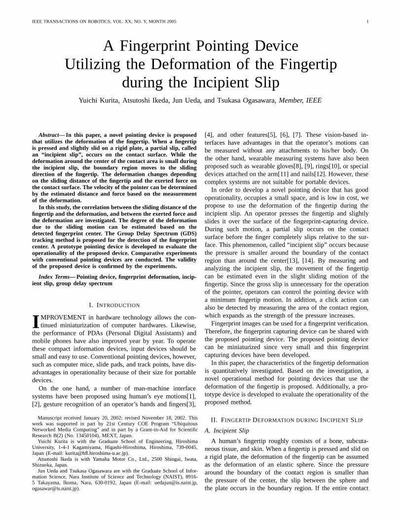
region slips, the sphere begins to slip relative to the plate.The partial slip of an elastic object, which occurs before thegross slip, is called an “incipient slip”. This phenomenoncan be approximately expressed in Fig.1. Johansson et al.have shown that perceiving the incipient slip is important forhuman’s sophisticated grasp[15]. In recent years, a numberof tactile sensors have been proposed, e.g., for detecting thecontact position[16], [17], the slippage[18], [19], [20], andfor distinguishing the difference of the friction coefficient[21],[22]. In order to examine the stick/slip state of the human’sfingertip during the incipient slip, a fingerprint measurementsystem is developed. The overview is shown in Fig.2(a). Asubject puts the hand on the table of the system and pressesthe index finger on the fingerprint capturing device (BMFCorporation, EZF-650, a pressure reaction type). The subject’shand is fixed on the table by a rubber belt and the index fingeris pinched on both sides. The fingerprint capturing device isfixed on a 3-axes stage so that the position of the sensor surfacecan be adjusted. Hereafter, the coordinate axes are defined asshown in Fig.2(b).
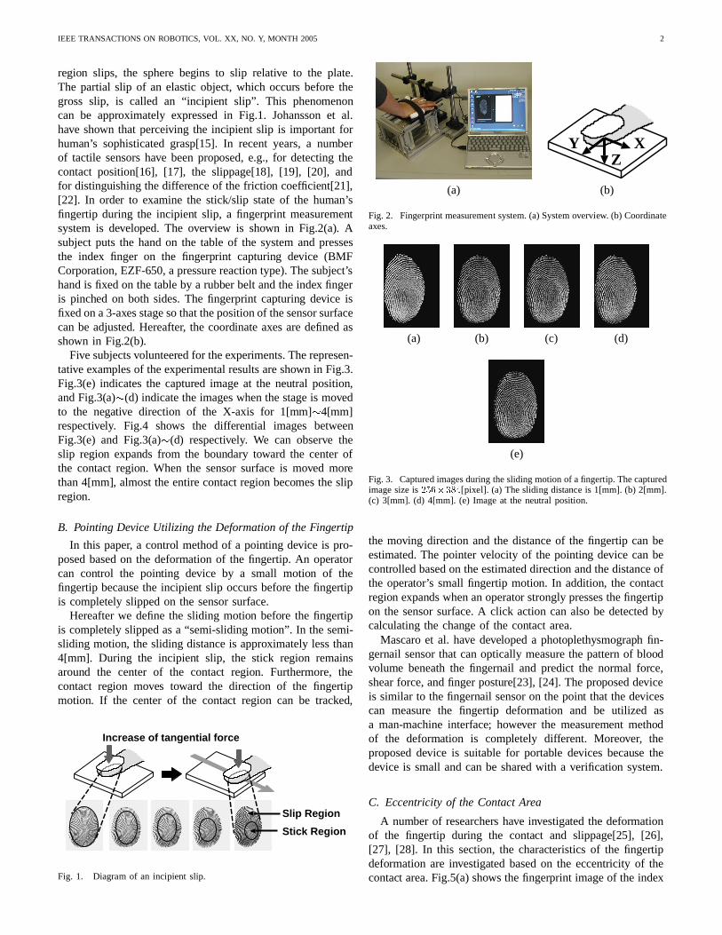
Five subjects volunteered for the experiments. The represen-tative examples of the experimental results are shown in Fig.3.Fig.3(e) indicates the captured image at the neutral position,and Fig.3(a)�(d) indicate the images when the stage is movedto the negative direction of the X-axis for 1[mm]�4[mm]respectively. Fig.4 shows the differential images betweenFig.3(e) and Fig.3(a)�(d) respectively. We can observe theslip region expands from the boundary toward the center ofthe contact region. When the sensor surface is moved morethan 4[mm], almost the entire contact region becomes the slipregion.
B. Pointing Device Utilizing the Deformation of the Fingertip
In this paper, a control method of a pointing device is pro-posed based on the deformation of the fingertip. An operatorcan control the pointing device by a small motion of thefingertip because the incipient slip occurs before the fingertipis completely slipped on the sensor surface.
Hereafter we define the sliding motion before the fingertipis completely slipped as a “semi-sliding motion”. In the semi-sliding motion, the sliding distance is approximately less than4[mm]. During the incipient slip, the stick region remainsaround the center of the contact region. Furthermore, thecontact region moves toward the direction of the fingertipmotion. If the center of the contact region can be tracked,
Increase of tangential force
Stick Region
Slip Region
Fig. 1. Diagram of an incipient slip.
XYZ
(a) (b)
Fig. 2. Fingerprint measurement system. (a) System overview. (b) Coordinateaxes.
(a) (b) (c) (d)
(e)
Fig. 3. Captured images during the sliding motion of a fingertip. The capturedimage size is �������[pixel]. (a) The sliding distance is 1[mm]. (b) 2[mm].(c) 3[mm]. (d) 4[mm]. (e) Image at the neutral position.
the moving direction and the distance of the fingertip can beestimated. The pointer velocity of the pointing device can becontrolled based on the estimated direction and the distance ofthe operator’s small fingertip motion. In addition, the contactregion expands when an operator strongly presses the fingertipon the sensor surface. A click action can also be detected bycalculating the change of the contact area.
Mascaro et al. have developed a photoplethysmograph fin-gernail sensor that can optically measure the pattern of bloodvolume beneath the fingernail and predict the normal force,shear force, and finger posture[23], [24]. The proposed deviceis similar to the fingernail sensor on the point that the devicescan measure the fingertip deformation and be utilized asa man-machine interface; however the measurement methodof the deformation is completely different. Moreover, theproposed device is suitable for portable devices because thedevice is small and can be shared with a verification system.
C. Eccentricity of the Contact Area
A number of researchers have investigated the deformationof the fingertip during the contact and slippage[25], [26],[27], [28]. In this section, the characteristics of the fingertipdeformation are investigated based on the eccentricity of thecontact area. Fig.5(a) shows the fingerprint image of the index
IEEE TRANSACTIONS ON ROBOTICS, VOL. XX, NO. Y, MONTH 2005 3
(a) (b) (c) (d)
Fig. 4. Differential between the image during the sliding motion and theimage at the neutral position. (a) The sliding distance is 1[mm]. (b) 2[mm].(c) 3[mm]. (d) 4[mm].
SS2 SS1
SS3 SS4
(a) (b)
Fig. 5. Segmentation of the contact area. (a) Original image. (b) Binarizedimage.
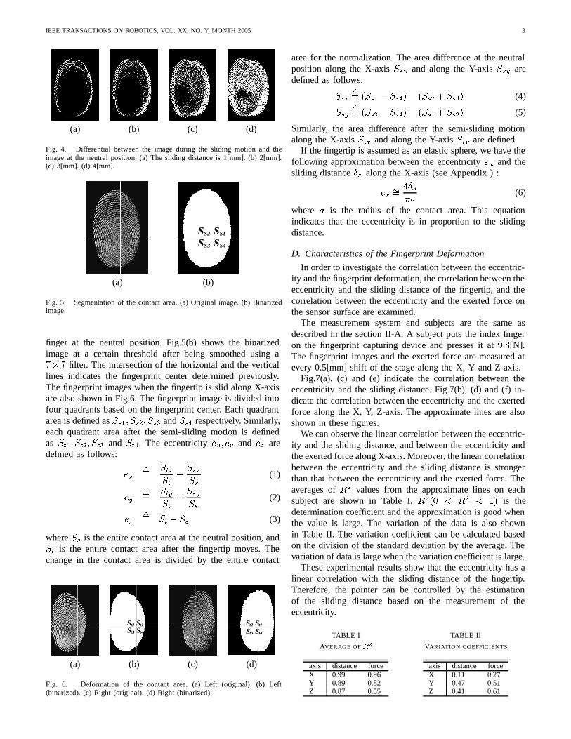
finger at the neutral position. Fig.5(b) shows the binarizedimage at a certain threshold after being smoothed using a�� � filter. The intersection of the horizontal and the verticallines indicates the fingerprint center determined previously.The fingerprint images when the fingertip is slid along X-axisare also shown in Fig.6. The fingerprint image is divided intofour quadrants based on the fingerprint center. Each quadrantarea is defined as ���� ���� ��� and ��� respectively. Similarly,each quadrant area after the semi-sliding motion is definedas ���� ���� ��� and ���. The eccentricity ��� �� and �� aredefined as follows:
����
�����
������
(1)
����
�����
������
(2)
���� �� � �� (3)
where �� is the entire contact area at the neutral position, and�� is the entire contact area after the fingertip moves. Thechange in the contact area is divided by the entire contact
t4St1St2S
t3S t4St1St2S
t3S
(a) (b) (c) (d)
Fig. 6. Deformation of the contact area. (a) Left (original). (b) Left(binarized). (c) Right (original). (d) Right (binarized).
area for the normalization. The area difference at the neutralposition along the X-axis ��� and along the Y-axis ��� aredefined as follows:
����� ���� � ����� ���� � ���� (4)
����� ���� � ����� ���� � ���� (5)
Similarly, the area difference after the semi-sliding motionalong the X-axis ��� and along the Y-axis ��� are defined.
If the fingertip is assumed as an elastic sphere, we have thefollowing approximation between the eccentricity �� and thesliding distance � along the X-axis (see Appendix ) :
�� ������
(6)
where � is the radius of the contact area. This equationindicates that the eccentricity is in proportion to the slidingdistance.
D. Characteristics of the Fingerprint Deformation
In order to investigate the correlation between the eccentric-ity and the fingerprint deformation, the correlation between theeccentricity and the sliding distance of the fingertip, and thecorrelation between the eccentricity and the exerted force onthe sensor surface are examined.
The measurement system and subjects are the same asdescribed in the section II-A. A subject puts the index fingeron the fingerprint capturing device and presses it at ���[N].The fingerprint images and the exerted force are measured atevery 0.5[mm] shift of the stage along the X, Y and Z-axis.
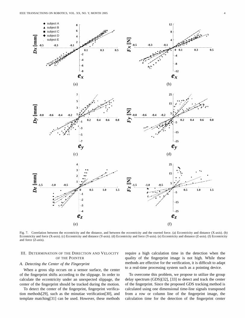
Fig.7(a), (c) and (e) indicate the correlation between theeccentricity and the sliding distance. Fig.7(b), (d) and (f) in-dicate the correlation between the eccentricity and the exertedforce along the X, Y, Z-axis. The approximate lines are alsoshown in these figures.
We can observe the linear correlation between the eccentric-ity and the sliding distance, and between the eccentricity andthe exerted force along X-axis. Moreover, the linear correlationbetween the eccentricity and the sliding distance is strongerthan that between the eccentricity and the exerted force. Theaverages of �� values from the approximate lines on eachsubject are shown in Table I. ���� � �� � � is thedetermination coefficient and the approximation is good whenthe value is large. The variation of the data is also shownin Table II. The variation coefficient can be calculated basedon the division of the standard deviation by the average. Thevariation of data is large when the variation coefficient is large.
These experimental results show that the eccentricity has alinear correlation with the sliding distance of the fingertip.Therefore, the pointer can be controlled by the estimationof the sliding distance based on the measurement of theeccentricity.
IEEE TRANSACTIONS ON ROBOTICS, VOL. XX, NO. Y, MONTH 2005 4
subject Asubject Bsubject Csubject Dsubject E*
8
6
4
2
-8
-6
-4
-2
-0.5 -0.3 -0.1
0.1 0.3 0.5Dx
[mm
]
xe
12
8
4
Fx
[N]
xe-12
-8
-4
0 0.50.30.1
-0.5 -0.3 -0.1
(a) (b)
7
5
3
1
-3
-5
0.2 0.4 0.6 0.8
-0.8 -0.6 -0.4 -0.2
Dy
[mm
]
ye-7
-1 Fy
[N]
ye
25
15
5
-25
-15
-50.60.40.2 0.8
-0.4-0.6-0.8 -0.2
(c) (d)
Dz
[mm
]
ze
4
3
2
1-1.5 -1.0 -0.5
1.51.00.5
-4
-3
-2
-10
ze
25
15
5
-25
-15
-5Fz
[N]
-0.5
0.5 1.0 1.5
-1.0-1.5
(e) (f)
Fig. 7. Correlation between the eccentricity and the distance, and between the eccentricity and the exerted force. (a) Eccentricity and distance (X-axis). (b)Eccentricity and force (X-axis). (c) Eccentricity and distance (Y-axis). (d) Eccentricity and force (Y-axis). (e) Eccentricity and distance (Z-axis). (f) Eccentricityand force (Z-axis).
III. DETERMINATION OF THE DIRECTION AND VELOCITY
OF THE POINTER
A. Detecting the Center of the Fingerprint
When a gross slip occurs on a sensor surface, the centerof the fingerprint shifts according to the slippage. In order tocalculate the eccentricity under an unexpected slippage, thecenter of the fingerprint should be tracked during the motion.
To detect the center of the fingerprint, fingerprint verifica-tion methods[29], such as the minutiae verification[30], andtemplate matching[31] can be used. However, these methods
require a high calculation time in the detection when thequality of the fingerprint image is not high. While thesemethods are effective for the verification, it is difficult to adaptto a real-time processing system such as a pointing device.
To overcome this problem, we propose to utilize the groupdelay spectrum (GDS)[32], [33] to detect and track the centerof the fingerprint. Since the proposed GDS tracking method iscalculated using one dimensional time-line signals transposedfrom a row or column line of the fingerprint image, thecalculation time for the detection of the fingerprint center
IEEE TRANSACTIONS ON ROBOTICS, VOL. XX, NO. Y, MONTH 2005 5
XY
0 2550
383
(a)
-50
0
50
100
150
200
0 50 100 150 200 250
Val
ue
X [pixel]
(b)
-3
-2
-1
0
1
2
3
4
0 5 10 15 20 25 30
Gd
Channels
(c)
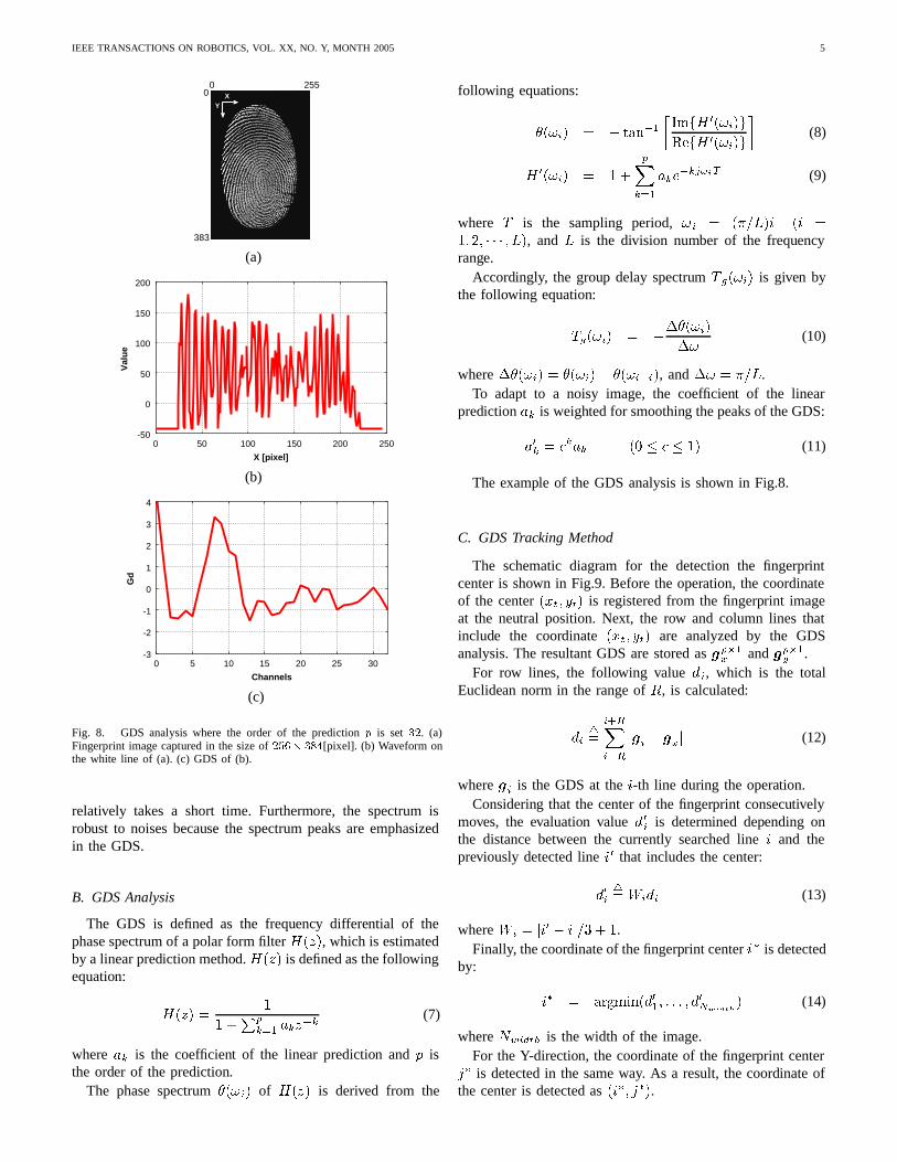
Fig. 8. GDS analysis where the order of the prediction � is set ��. (a)Fingerprint image captured in the size of ���� ���[pixel]. (b) Waveform onthe white line of (a). (c) GDS of (b).
relatively takes a short time. Furthermore, the spectrum isrobust to noises because the spectrum peaks are emphasizedin the GDS.
B. GDS Analysis
The GDS is defined as the frequency differential of thephase spectrum of a polar form filter ���, which is estimatedby a linear prediction method. ��� is defined as the followingequation:
��� �
���
��� ����
(7)
where �� is the coefficient of the linear prediction and isthe order of the prediction.
The phase spectrum ����� of ��� is derived from the
following equations:
����� � � ����� ��� ������
���� ������
�(8)
� ����� � �
�����
������� (9)
where is the sampling period, �� � ������ �� �� �� � � � � ��, and � is the division number of the frequencyrange.
Accordingly, the group delay spectrum ����� is given bythe following equation:
����� � �������
��(10)
where ������ � ������ �������, and �� � ���.To adapt to a noisy image, the coefficient of the linear
prediction �� is weighted for smoothing the peaks of the GDS:
��� � ���� �� � � � � (11)
The example of the GDS analysis is shown in Fig.8.
C. GDS Tracking Method
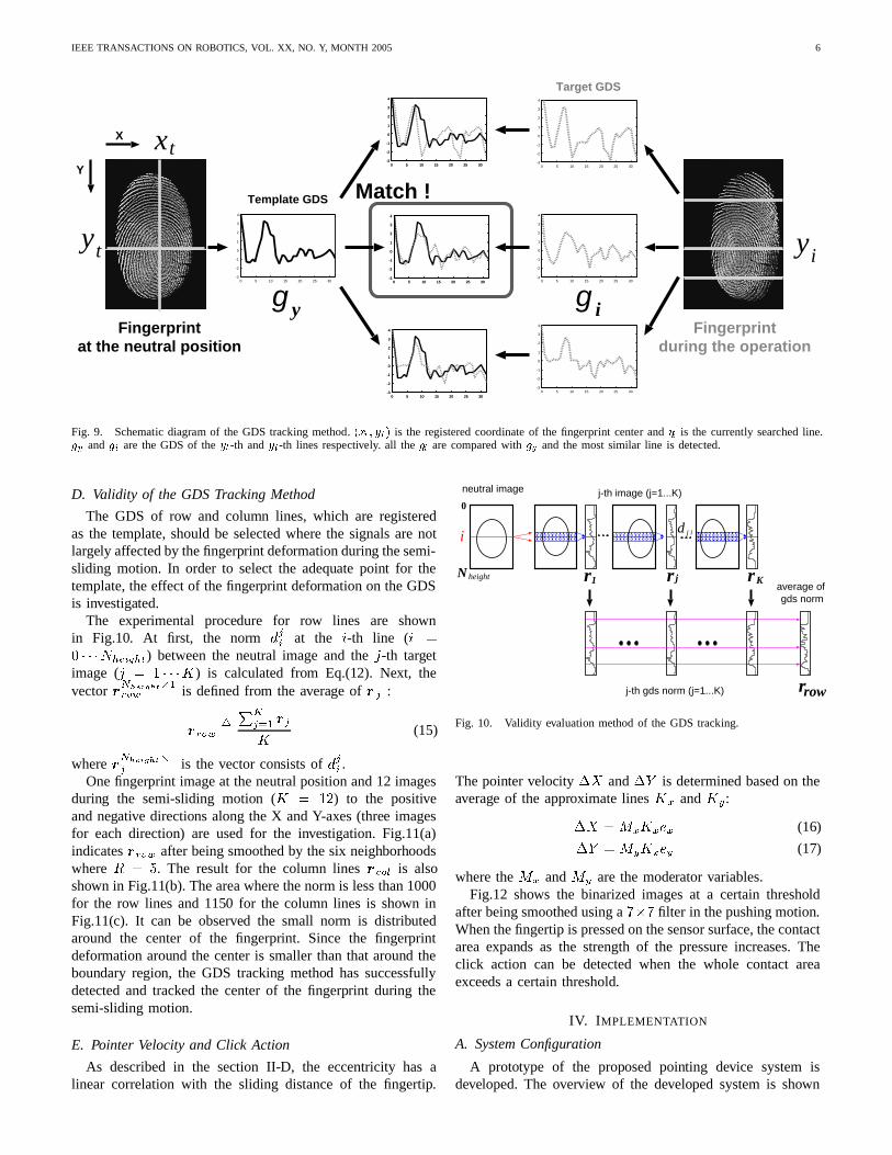
The schematic diagram for the detection the fingerprintcenter is shown in Fig.9. Before the operation, the coordinateof the center ���� ��� is registered from the fingerprint imageat the neutral position. Next, the row and column lines thatinclude the coordinate ���� ��� are analyzed by the GDSanalysis. The resultant GDS are stored as �
���� and �
���� .
For row lines, the following value ��, which is the totalEuclidean norm in the range of �, is calculated:
����
�������
��� � ��� (12)
where �� is the GDS at the �-th line during the operation.Considering that the center of the fingerprint consecutively
moves, the evaluation value ��� is determined depending onthe distance between the currently searched line � and thepreviously detected line �� that includes the center:
����� ���� (13)
where �� � ��� � ���� � .Finally, the coordinate of the fingerprint center �� is detected
by:
�� � ����������� � � � � ��
������ (14)
where ������ is the width of the image.For the Y-direction, the coordinate of the fingerprint center
�� is detected in the same way. As a result, the coordinate ofthe center is detected as ���� ���.
IEEE TRANSACTIONS ON ROBOTICS, VOL. XX, NO. Y, MONTH 2005 6
Fingerprintat the neutral position
-3
-2
-1
0
1
2
3
4
0 5 10 15 20 25 30-3
-2
-1
0
1
2
3
4
0 5 10 15 20 25 30
-3
-2
-1
0
1
2
3
4
0 5 10 15 20 25 30-3
-2
-1
0
1
2
3
4
0 5 10 15 20 25 30
-3
-2
-1
0
1
2
3
4
0 5 10 15 20 25 30
Match !
-3
-2
-1
0
1
2
3
4
0 5 10 15 20 25 30-3
-2
-1
0
1
2
3
4
0 5 10 15 20 25 30
-3
-2
-1
0
1
2
3
4
0 5 10 15 20 25 30
-3
-2
-1
0
1
2
3
4
0 5 10 15 20 25 30
-3
-2
-1
0
1
2
3
4
0 5 10 15 20 25 30
Template GDS
Target GDS
X
Y
Fingerprintduring the operation
yt
xt
g y g i
yi
Fig. 9. Schematic diagram of the GDS tracking method. ���� ��� is the registered coordinate of the fingerprint center and �� is the currently searched line.�� and �� are the GDS of the ��-th and ��-th lines respectively. all the �� are compared with �� and the most similar line is detected.
D. Validity of the GDS Tracking Method
The GDS of row and column lines, which are registeredas the template, should be selected where the signals are notlargely affected by the fingerprint deformation during the semi-sliding motion. In order to select the adequate point for thetemplate, the effect of the fingerprint deformation on the GDSis investigated.
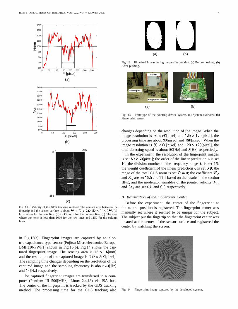
The experimental procedure for row lines are shownin Fig.10. At first, the norm ��� at the �-th line (� �� � � ��������) between the neutral image and the �-th targetimage (� � � � ��) is calculated from Eq.(12). Next, thevector � ��������
��� is defined from the average of � � :
������
����� ��
�(15)
where � ��������
� is the vector consists of ��� .One fingerprint image at the neutral position and 12 images
during the semi-sliding motion (� � �) to the positiveand negative directions along the X and Y-axes (three imagesfor each direction) are used for the investigation. Fig.11(a)indicates ���� after being smoothed by the six neighborhoodswhere � � �. The result for the column lines ���� is alsoshown in Fig.11(b). The area where the norm is less than 1000for the row lines and 1150 for the column lines is shown inFig.11(c). It can be observed the small norm is distributedaround the center of the fingerprint. Since the fingerprintdeformation around the center is smaller than that around theboundary region, the GDS tracking method has successfullydetected and tracked the center of the fingerprint during thesemi-sliding motion.
E. Pointer Velocity and Click Action
As described in the section II-D, the eccentricity has alinear correlation with the sliding distance of the fingertip.
i
neutral image j-th image (j=1...K)
average of gds norm
0
d j i
j-th gds norm (j=1...K)
r1 rj rKN height
rrow
Fig. 10. Validity evaluation method of the GDS tracking.
The pointer velocity �� and �� is determined based on theaverage of the approximate lines �� and ��:
�� � ������ (16)
�� � ������ (17)
where the �� and �� are the moderator variables.Fig.12 shows the binarized images at a certain threshold
after being smoothed using a ��� filter in the pushing motion.When the fingertip is pressed on the sensor surface, the contactarea expands as the strength of the pressure increases. Theclick action can be detected when the whole contact areaexceeds a certain threshold.
IV. IMPLEMENTATION
A. System Configuration
A prototype of the proposed pointing device system isdeveloped. The overview of the developed system is shown
IEEE TRANSACTIONS ON ROBOTICS, VOL. XX, NO. Y, MONTH 2005 7
Y [pixel]
Nor
m
1400
1300
1200
1100
1000
900
800
700
6000 50 100 150 200 250 300 350
(a)
Nor
m
1400
1350
1300
1250
1200
1150
1100
1050
1000
950
900
X [pixel]50 100 150 200 2500
(b)
0 2550
383
(c)
Fig. 11. Validity of the GDS tracking method. The contact area between thefingertip and the sensor surface is about �� � � � ���, �� � � � ���. (a)GDS norm for the row line. (b) GDS norm for the column line. (c) The areawhere the norm is less than 1000 for the row lines and 1150 for the columnlines.
in Fig.13(a). Fingerprint images are captured by an elec-tric capacitance-type sensor (Fujitsu Microelectronics Europe,BMF110-PWF1) shown in Fig.13(b). Fig.14 shows the cap-tured fingerprint image. The sensing area is � � �[mm]and the resolution of the captured image is ���� ���[pixel].The sampling time changes depending on the resolution of thecaptured image and the sampling frequency is about ��[Hz]and �[Hz] respectively.
The captured fingerprint images are transferred to a com-puter (Pentium III 500[MHz], Linux 2.4.18) via ISA bus.The center of the fingerprint is tracked by the GDS trackingmethod. The processing time for the GDS tracking also
(a) (b)
Fig. 12. Binarized image during the pushing motion. (a) Before pushing. (b)After pushing.
Desktop PC
Screen
Fingerprint sensor
(a) (b)
Fig. 13. Prototype of the pointing device system. (a) System overview. (b)Fingerprint sensor.
changes depending on the resolution of the image. When theimage resolution is �� � ��[pixel] and ��� ��[pixel], theprocessing time are about ��[msec] and ��[msec]. When theimage resolution is �� � ��[pixel] and ��� ��[pixel], thetotal detecting speed is about ��[Hz] and �[Hz] respectively.
In the experiment, the resolution of the fingerprint imagesis set �����[pixel]; the order of the linear prediction is set�; the division number of the frequency range � is set �;the weight coefficient of the linear prediction � is set ���; therange of the total GDS norm is set � � �; the coefficient ��
and �� are set ��� and � based on the results in the sectionIII-E, and the moderator variables of the pointer velocity � �
and �� are set ��� and ��� respectively.
B. Registration of the Fingerprint Center
Before the experiment, the center of the fingerprint atthe neutral position is registered. The fingerprint center wasmanually set where it seemed to be unique for the subject.The subject put the fingertip so that the fingerprint center waslocated at the center of the sensor surface and registered thecenter by watching the screen.
Fig. 14. Fingerprint image captured by the developed system.
IEEE TRANSACTIONS ON ROBOTICS, VOL. XX, NO. Y, MONTH 2005 8
Each subject is required to register the fingerprint centeronce before the operation. In this experiment, the subjectsmanually registered the center, but an automatic registrationtool has been developed that can register the fingerprint centerwhen the subject puts the fingertip on the sensor surface.
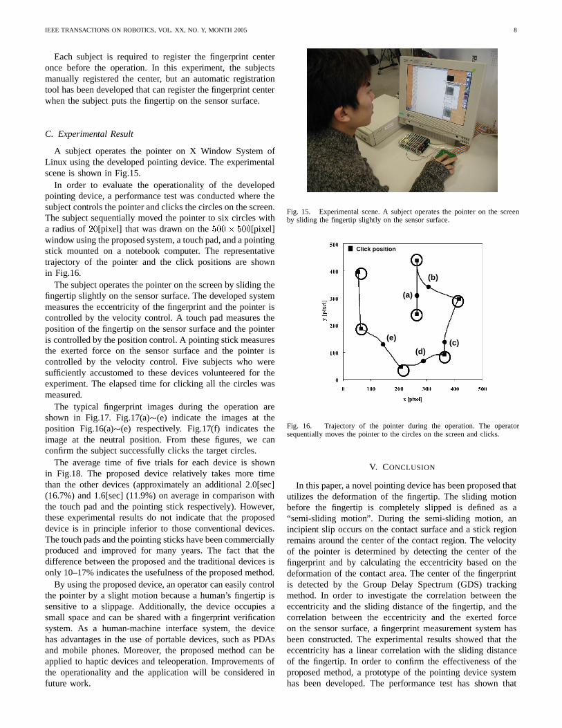
C. Experimental Result
A subject operates the pointer on X Window System ofLinux using the developed pointing device. The experimentalscene is shown in Fig.15.
In order to evaluate the operationality of the developedpointing device, a performance test was conducted where thesubject controls the pointer and clicks the circles on the screen.The subject sequentially moved the pointer to six circles witha radius of ��[pixel] that was drawn on the ���� ���[pixel]window using the proposed system, a touch pad, and a pointingstick mounted on a notebook computer. The representativetrajectory of the pointer and the click positions are shownin Fig.16.
The subject operates the pointer on the screen by sliding thefingertip slightly on the sensor surface. The developed systemmeasures the eccentricity of the fingerprint and the pointer iscontrolled by the velocity control. A touch pad measures theposition of the fingertip on the sensor surface and the pointeris controlled by the position control. A pointing stick measuresthe exerted force on the sensor surface and the pointer iscontrolled by the velocity control. Five subjects who weresufficiently accustomed to these devices volunteered for theexperiment. The elapsed time for clicking all the circles wasmeasured.
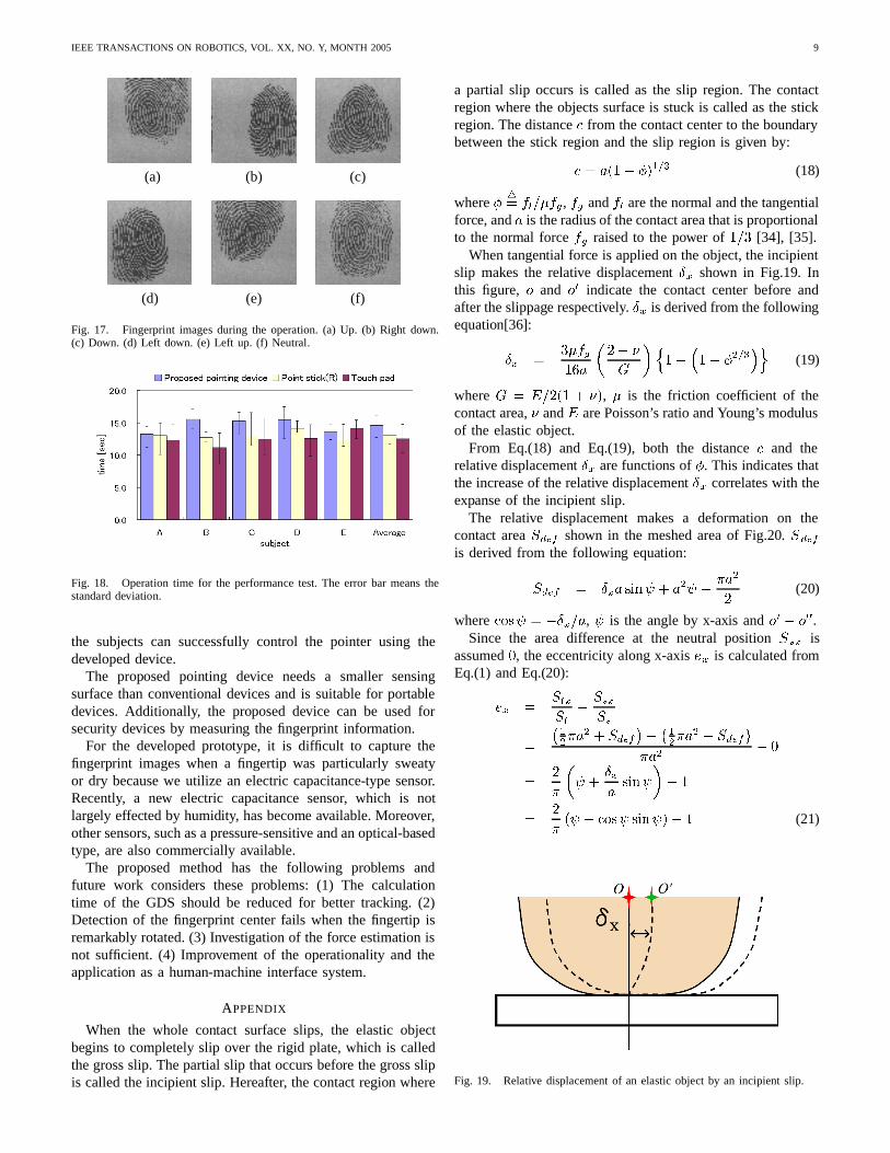
The typical fingerprint images during the operation areshown in Fig.17. Fig.17(a)�(e) indicate the images at theposition Fig.16(a)�(e) respectively. Fig.17(f) indicates theimage at the neutral position. From these figures, we canconfirm the subject successfully clicks the target circles.
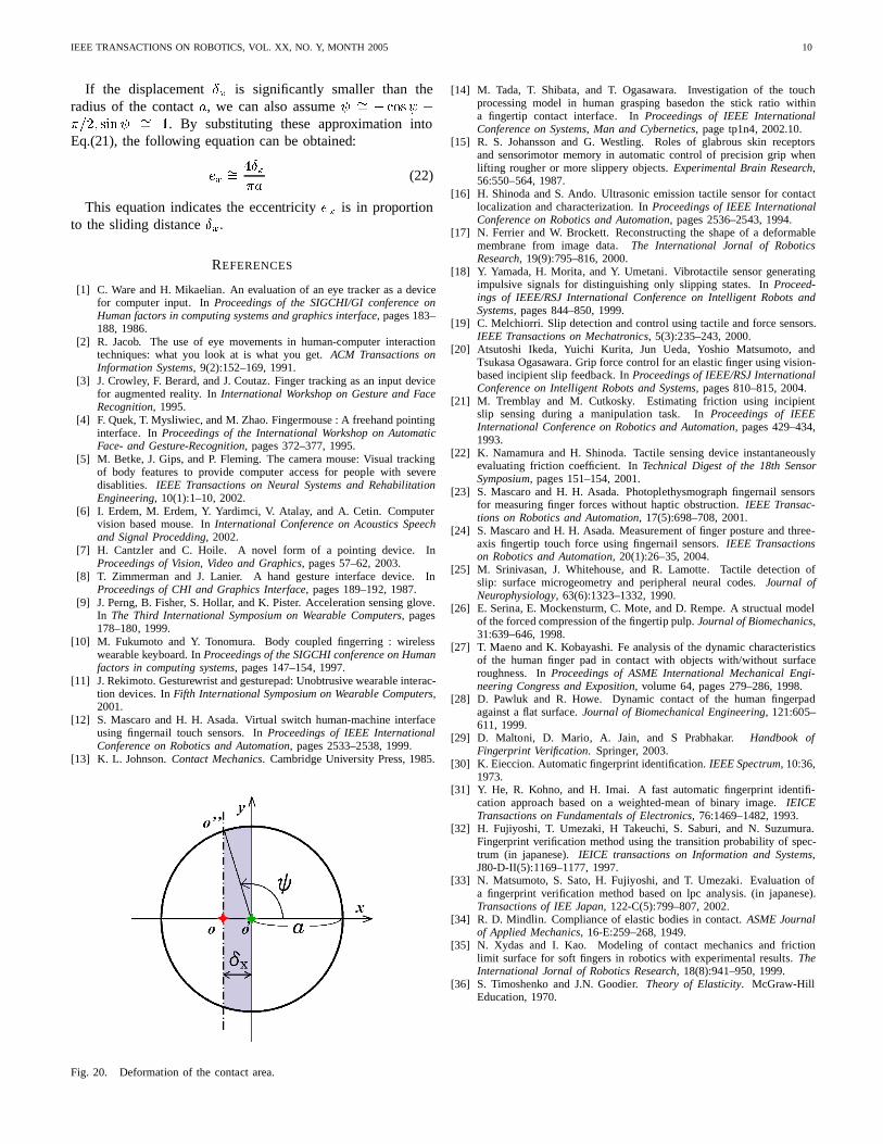
The average time of five trials for each device is shownin Fig.18. The proposed device relatively takes more timethan the other devices (approximately an additional 2.0[sec](16.7%) and 1.6[sec] (11.9%) on average in comparison withthe touch pad and the pointing stick respectively). However,these experimental results do not indicate that the proposeddevice is in principle inferior to those conventional devices.The touch pads and the pointing sticks have been commerciallyproduced and improved for many years. The fact that thedifference between the proposed and the traditional devices isonly 10–17% indicates the usefulness of the proposed method.
By using the proposed device, an operator can easily controlthe pointer by a slight motion because a human’s fingertip issensitive to a slippage. Additionally, the device occupies asmall space and can be shared with a fingerprint verificationsystem. As a human-machine interface system, the devicehas advantages in the use of portable devices, such as PDAsand mobile phones. Moreover, the proposed method can beapplied to haptic devices and teleoperation. Improvements ofthe operationality and the application will be considered infuture work.
Fig. 15. Experimental scene. A subject operates the pointer on the screenby sliding the fingertip slightly on the sensor surface.
(a)
(b)
(c)(d)
(e)
Click position
Fig. 16. Trajectory of the pointer during the operation. The operatorsequentially moves the pointer to the circles on the screen and clicks.
V. CONCLUSION
In this paper, a novel pointing device has been proposed thatutilizes the deformation of the fingertip. The sliding motionbefore the fingertip is completely slipped is defined as a“semi-sliding motion”. During the semi-sliding motion, anincipient slip occurs on the contact surface and a stick regionremains around the center of the contact region. The velocityof the pointer is determined by detecting the center of thefingerprint and by calculating the eccentricity based on thedeformation of the contact area. The center of the fingerprintis detected by the Group Delay Spectrum (GDS) trackingmethod. In order to investigate the correlation between theeccentricity and the sliding distance of the fingertip, and thecorrelation between the eccentricity and the exerted forceon the sensor surface, a fingerprint measurement system hasbeen constructed. The experimental results showed that theeccentricity has a linear correlation with the sliding distanceof the fingertip. In order to confirm the effectiveness of theproposed method, a prototype of the pointing device systemhas been developed. The performance test has shown that
IEEE TRANSACTIONS ON ROBOTICS, VOL. XX, NO. Y, MONTH 2005 9
(a) (b) (c)
(d) (e) (f)
Fig. 17. Fingerprint images during the operation. (a) Up. (b) Right down.(c) Down. (d) Left down. (e) Left up. (f) Neutral.
Fig. 18. Operation time for the performance test. The error bar means thestandard deviation.
the subjects can successfully control the pointer using thedeveloped device.
The proposed pointing device needs a smaller sensingsurface than conventional devices and is suitable for portabledevices. Additionally, the proposed device can be used forsecurity devices by measuring the fingerprint information.
For the developed prototype, it is difficult to capture thefingerprint images when a fingertip was particularly sweatyor dry because we utilize an electric capacitance-type sensor.Recently, a new electric capacitance sensor, which is notlargely effected by humidity, has become available. Moreover,other sensors, such as a pressure-sensitive and an optical-basedtype, are also commercially available.
The proposed method has the following problems andfuture work considers these problems: (1) The calculationtime of the GDS should be reduced for better tracking. (2)Detection of the fingerprint center fails when the fingertip isremarkably rotated. (3) Investigation of the force estimation isnot sufficient. (4) Improvement of the operationality and theapplication as a human-machine interface system.
APPENDIX
When the whole contact surface slips, the elastic objectbegins to completely slip over the rigid plate, which is calledthe gross slip. The partial slip that occurs before the gross slipis called the incipient slip. Hereafter, the contact region where
a partial slip occurs is called as the slip region. The contactregion where the objects surface is stuck is called as the stickregion. The distance � from the contact center to the boundarybetween the stick region and the slip region is given by:
� � ��� ����� (18)
where ��� ������, �� and �� are the normal and the tangential
force, and � is the radius of the contact area that is proportionalto the normal force �� raised to the power of �� [34], [35].
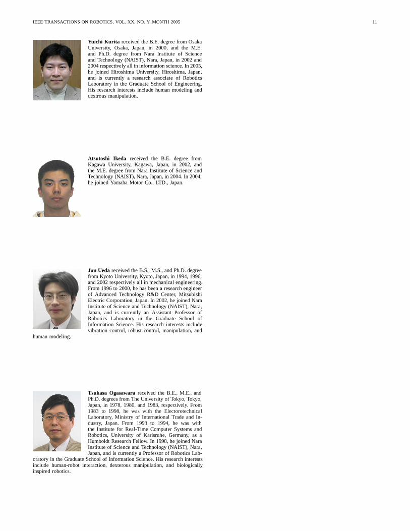
When tangential force is applied on the object, the incipientslip makes the relative displacement � shown in Fig.19. Inthis figure, � and �� indicate the contact center before andafter the slippage respectively. � is derived from the followingequation[36]:
� �������
���
!
���
�� ����
�(19)
where ! � "��� � �, � is the friction coefficient of thecontact area, and " are Poisson’s ratio and Young’s modulusof the elastic object.
From Eq.(18) and Eq.(19), both the distance � and therelative displacement � are functions of �. This indicates thatthe increase of the relative displacement � correlates with theexpanse of the incipient slip.
The relative displacement makes a deformation on thecontact area ���� shown in the meshed area of Fig.20. ����
is derived from the following equation:
���� � �� ���# � ��# ����
�(20)
where ���# � ����, # is the angle by x-axis and �� � ���.Since the area difference at the neutral position ��� is
assumed �, the eccentricity along x-axis �� is calculated fromEq.(1) and Eq.(20):
�� ������
������
�
�
���� � ����
���
���� � ����
����
� �
��
�
�# �
�����#
��
��
��# � ���# ���#�� (21)
Fig. 19. Relative displacement of an elastic object by an incipient slip.
IEEE TRANSACTIONS ON ROBOTICS, VOL. XX, NO. Y, MONTH 2005 10
If the displacement � is significantly smaller than theradius of the contact �, we can also assume # �� � ���# ����� ���# �� . By substituting these approximation intoEq.(21), the following equation can be obtained:
�� ������
(22)
This equation indicates the eccentricity �� is in proportionto the sliding distance �.
REFERENCES
[1] C. Ware and H. Mikaelian. An evaluation of an eye tracker as a devicefor computer input. In Proceedings of the SIGCHI/GI conference onHuman factors in computing systems and graphics interface, pages 183–188, 1986.
[2] R. Jacob. The use of eye movements in human-computer interactiontechniques: what you look at is what you get. ACM Transactions onInformation Systems, 9(2):152–169, 1991.
[3] J. Crowley, F. Berard, and J. Coutaz. Finger tracking as an input devicefor augmented reality. In International Workshop on Gesture and FaceRecognition, 1995.
[4] F. Quek, T. Mysliwiec, and M. Zhao. Fingermouse : A freehand pointinginterface. In Proceedings of the International Workshop on AutomaticFace- and Gesture-Recognition, pages 372–377, 1995.
[5] M. Betke, J. Gips, and P. Fleming. The camera mouse: Visual trackingof body features to provide computer access for people with severedisablities. IEEE Transactions on Neural Systems and RehabilitationEngineering, 10(1):1–10, 2002.
[6] I. Erdem, M. Erdem, Y. Yardimci, V. Atalay, and A. Cetin. Computervision based mouse. In International Conference on Acoustics Speechand Signal Procedding, 2002.
[7] H. Cantzler and C. Hoile. A novel form of a pointing device. InProceedings of Vision, Video and Graphics, pages 57–62, 2003.
[8] T. Zimmerman and J. Lanier. A hand gesture interface device. InProceedings of CHI and Graphics Interface, pages 189–192, 1987.
[9] J. Perng, B. Fisher, S. Hollar, and K. Pister. Acceleration sensing glove.In The Third International Symposium on Wearable Computers, pages178–180, 1999.
[10] M. Fukumoto and Y. Tonomura. Body coupled fingerring : wirelesswearable keyboard. In Proceedings of the SIGCHI conference on Humanfactors in computing systems, pages 147–154, 1997.
[11] J. Rekimoto. Gesturewrist and gesturepad: Unobtrusive wearable interac-tion devices. In Fifth International Symposium on Wearable Computers,2001.
[12] S. Mascaro and H. H. Asada. Virtual switch human-machine interfaceusing fingernail touch sensors. In Proceedings of IEEE InternationalConference on Robotics and Automation, pages 2533–2538, 1999.
[13] K. L. Johnson. Contact Mechanics. Cambridge University Press, 1985.
Fig. 20. Deformation of the contact area.
[14] M. Tada, T. Shibata, and T. Ogasawara. Investigation of the touchprocessing model in human grasping basedon the stick ratio withina fingertip contact interface. In Proceedings of IEEE InternationalConference on Systems, Man and Cybernetics, page tp1n4, 2002.10.
[15] R. S. Johansson and G. Westling. Roles of glabrous skin receptorsand sensorimotor memory in automatic control of precision grip whenlifting rougher or more slippery objects. Experimental Brain Research,56:550–564, 1987.
[16] H. Shinoda and S. Ando. Ultrasonic emission tactile sensor for contactlocalization and characterization. In Proceedings of IEEE InternationalConference on Robotics and Automation, pages 2536–2543, 1994.
[17] N. Ferrier and W. Brockett. Reconstructing the shape of a deformablemembrane from image data. The International Jornal of RoboticsResearch, 19(9):795–816, 2000.
[18] Y. Yamada, H. Morita, and Y. Umetani. Vibrotactile sensor generatingimpulsive signals for distinguishing only slipping states. In Proceed-ings of IEEE/RSJ International Conference on Intelligent Robots andSystems, pages 844–850, 1999.
[19] C. Melchiorri. Slip detection and control using tactile and force sensors.IEEE Transactions on Mechatronics, 5(3):235–243, 2000.
[20] Atsutoshi Ikeda, Yuichi Kurita, Jun Ueda, Yoshio Matsumoto, andTsukasa Ogasawara. Grip force control for an elastic finger using vision-based incipient slip feedback. In Proceedings of IEEE/RSJ InternationalConference on Intelligent Robots and Systems, pages 810–815, 2004.
[21] M. Tremblay and M. Cutkosky. Estimating friction using incipientslip sensing during a manipulation task. In Proceedings of IEEEInternational Conference on Robotics and Automation, pages 429–434,1993.
[22] K. Namamura and H. Shinoda. Tactile sensing device instantaneouslyevaluating friction coefficient. In Technical Digest of the 18th SensorSymposium, pages 151–154, 2001.
[23] S. Mascaro and H. H. Asada. Photoplethysmograph fingernail sensorsfor measuring finger forces without haptic obstruction. IEEE Transac-tions on Robotics and Automation, 17(5):698–708, 2001.
[24] S. Mascaro and H. H. Asada. Measurement of finger posture and three-axis fingertip touch force using fingernail sensors. IEEE Transactionson Robotics and Automation, 20(1):26–35, 2004.
[25] M. Srinivasan, J. Whitehouse, and R. Lamotte. Tactile detection ofslip: surface microgeometry and peripheral neural codes. Journal ofNeurophysiology, 63(6):1323–1332, 1990.
[26] E. Serina, E. Mockensturm, C. Mote, and D. Rempe. A structual modelof the forced compression of the fingertip pulp. Journal of Biomechanics,31:639–646, 1998.
[27] T. Maeno and K. Kobayashi. Fe analysis of the dynamic characteristicsof the human finger pad in contact with objects with/without surfaceroughness. In Proceedings of ASME International Mechanical Engi-neering Congress and Exposition, volume 64, pages 279–286, 1998.
[28] D. Pawluk and R. Howe. Dynamic contact of the human fingerpadagainst a flat surface. Journal of Biomechanical Engineering, 121:605–611, 1999.
[29] D. Maltoni, D. Mario, A. Jain, and S Prabhakar. Handbook ofFingerprint Verification. Springer, 2003.
[30] K. Eieccion. Automatic fingerprint identification. IEEE Spectrum, 10:36,1973.
[31] Y. He, R. Kohno, and H. Imai. A fast automatic fingerprint identifi-cation approach based on a weighted-mean of binary image. IEICETransactions on Fundamentals of Electronics, 76:1469–1482, 1993.
[32] H. Fujiyoshi, T. Umezaki, H Takeuchi, S. Saburi, and N. Suzumura.Fingerprint verification method using the transition probability of spec-trum (in japanese). IEICE transactions on Information and Systems,J80-D-II(5):1169–1177, 1997.
[33] N. Matsumoto, S. Sato, H. Fujiyoshi, and T. Umezaki. Evaluation ofa fingerprint verification method based on lpc analysis. (in japanese).Transactions of IEE Japan, 122-C(5):799–807, 2002.
[34] R. D. Mindlin. Compliance of elastic bodies in contact. ASME Journalof Applied Mechanics, 16-E:259–268, 1949.
[35] N. Xydas and I. Kao. Modeling of contact mechanics and frictionlimit surface for soft fingers in robotics with experimental results. TheInternational Jornal of Robotics Research, 18(8):941–950, 1999.
[36] S. Timoshenko and J.N. Goodier. Theory of Elasticity. McGraw-HillEducation, 1970.
IEEE TRANSACTIONS ON ROBOTICS, VOL. XX, NO. Y, MONTH 2005 11
Yuichi Kurita received the B.E. degree from OsakaUniversity, Osaka, Japan, in 2000, and the M.E.and Ph.D. degree from Nara Institute of Scienceand Technology (NAIST), Nara, Japan, in 2002 and2004 respectively all in information science. In 2005,he joined Hiroshima University, Hiroshima, Japan,and is currently a research associate of RoboticsLaboratory in the Graduate School of Engineering.His research interests include human modeling anddextrous manipulation.
Atsutoshi Ikeda received the B.E. degree fromKagawa University, Kagawa, Japan, in 2002, andthe M.E. degree from Nara Institute of Science andTechnology (NAIST), Nara, Japan, in 2004. In 2004,he joined Yamaha Motor Co., LTD., Japan.
Jun Ueda received the B.S., M.S., and Ph.D. degreefrom Kyoto University, Kyoto, Japan, in 1994, 1996,and 2002 respectively all in mechanical engineering.From 1996 to 2000, he has been a research engineerof Advanced Technology R&D Center, MitsubishiElectric Corporation, Japan. In 2002, he joined NaraInstitute of Science and Technology (NAIST), Nara,Japan, and is currently an Assistant Professor ofRobotics Laboratory in the Graduate School ofInformation Science. His research interests includevibration control, robust control, manipulation, and
human modeling.
Tsukasa Ogasawara received the B.E., M.E., andPh.D. degrees from The University of Tokyo, Tokyo,Japan, in 1978, 1980, and 1983, respectively. From1983 to 1998, he was with the ElectorotechnicalLaboratory, Ministry of International Trade and In-dustry, Japan. From 1993 to 1994, he was withthe Institute for Real-Time Computer Systems andRobotics, University of Karlsruhe, Germany, as aHumboldt Research Fellow. In 1998, he joined NaraInstitute of Science and Technology (NAIST), Nara,Japan, and is currently a Professor of Robotics Lab-
oratory in the Graduate School of Information Science. His research interestsinclude human-robot interaction, dexterous manipulation, and biologicallyinspired robotics.