1083-4435 (c) 2015 IEEE. Personal use is permitted, but republication/redistribution requires IEEE permission. See http://www.ieee.org/publications_standards/publications/rights/index.html for more information. This article has been accepted for publication in a future issue of this journal, but has not been fully edited. Content may change prior to final publication. Citation information: DOI 10.1109/TMECH.2015.2478658, IEEE/ASME Transactions on Mechatronics IEEE/ASME TRANSACTIONS ON MECHATRONICS, VOL. XX, NO. X, XXX 2015 1 Comparison and Classification of High-precision Actuators Based on Stiffness Influencing Vibration Isolation Shingo Ito and Georg Schitter, Senior Member, IEEE, Abstract—Positioning performance of high-precision systems is influenced by vibrations transmitting from floors and types of the precision actuators. To construct a compact actuator with high vibration isolation for these systems, this paper investigates and categorizes precision actuators based on their stiffness for providing design rules. The effectiveness of the analysis and the design rules is confirmed by experiments comparing two types of compact precision actuators: piezoelectric and electromagnetic (Lorentz, or voice coil) actuators. The positioning system with these actuators is validated experimentally by applying step- like disturbances of approximately 160 nm to the base of the actuators. While the position error of the piezo-actuated system swings by about ± 200 nm, the Lorentz-actuated system that satisfies the design rules is able to suppress the error within a range of ± 10 nm. Index Terms—Motion control, actuators, vibrations. I. I NTRODUCTION M OTION control with nanometer resolution is indis- pensable for high-precision manufacturing machines, measurement instruments and data storage devices, such as wafer scanners [1], atomic force microscopes (AFMs) [2] and hard disk drives [3], [4]. For these systems, one of the common disturbances is vibrations transmitting from the environment. These vibrations can be reduced by using a vibration isolator as a platform [5], [6]. By selecting appropriate precision actuators, the high performance systems themselves can have high immunity against the floor vibrations, where the vibration immunity of precision actuators is related with their stiffness between the base and the moving part. They can be catego- rized into three groups: zero-stiffness, low-stiffness and high- stiffness actuators [7], [8]. Zero-stiffness actuators include Lorentz actuators [7], [9], where their bases (i.e. stators) and moving parts are physically decoupled by design. Since there is no mechanical connection to transmit vibrations, the moving part is not influenced by the disturbances from the base. As a result, a system with zero-stiffness actuators can achieve a position error of the nanometer level even during motion at a constant speed [1], [10]. However, in order to suspend the moving part, for example by air feet or magnetic levitation, zero-stiffness actuated systems are usually larger and heavier, limiting their achievable acceleration and positioning bandwidth [7]. (Note This work has been supported in part by the Austrian Research Promotion Agency (FFG) under project number 836489. S. Ito and G. Schitter are with the Automation and Control Institute (ACIN), the Vienna University of Technology, A-1040 Vienna, Austria, e-mail: {ito, schitter}@acin.tuwien.ac.at). that Lorentz actuators consist of coils and magnets for the Lorentz force and include voice coil actuators.) In contrast to zero-stiffness actuators, low-stiffness actuators can be compact by design to support their moving part by mechanical components with lowered stiffness [8], where typically the Lorentz force is used for the actuation [11]. While the low stiffness reduces transmitting forces due to the vibrations from the base, the residual vibrations are rejected by feedback control [8]. The control bandwidth is usually limited not by the suspension resonance, but by the internal modes of the moving part [12]. Since it can be light and rigid due to the compact design, the resonant frequencies of internal modes can be high enough. Consequently, sufficiently high control bandwidth can be achieved with feedback control for good disturbance rejection. For example, a low-stiffness system with carefully designed feedback control can position with nanometer resolution even without an additional vibration isolation [8]. These actuators are typically found in applica- tions with low load capacity, for example optical disk drives [13], [14]. This might be to some extent because the supports with lowered stiffness have difficulties to hold a heavy mass under gravity. High-stiffness actuators include piezoelectric actuators, which have a high intrinsic stiffness between the base and the moving part (i.e. fixed and moving end pieces) [7]. Piezo actuators can be easily miniaturized and are used for applications with extremely high control bandwidth [15], [16]. The control bandwidth of these piezo systems with feedback control is typically limited by their first or second mechanical resonance [17], [18]. Since the resonant frequency can be increased by a high stiffness of the systems, the stiffness of the piezo material itself contributes to the high resonance [19]. However, the high stiffness strongly transmits the disturbances from the base, deteriorating the positioning precision [7]. The advantages and disadvantages of each actuator category are summarized in Table I. In this actuator classification, zero- stiffness actuators are defined as ones having no mechanical stiffness between the base and the moving part [7]. In contrast, the border between low- and high-stiffness actuators is not well-defined, and thus it is unclear what stiffness is ideal to design a compact actuator with good vibration isolation capabilities. To find this border, this paper analytically inves- tigates high-precision actuators and experimentally compares Lorentz and piezo actuated systems, resulting in a design rule to develop low-stiffness actuators that have good vibration isolation properties. In addition, the rule is related to a design Post-print version (generated on 19.03.2020) This and other publications are available at: http://www.acin.tuwien.ac.at/publikationen/ams/ Post-print version of the article: S. Ito and G. Schitter, “Comparison and Classification of High-Precision Actuators Based on Stiffness Influencing Vibration Isolation,” IEEE/ASME Transactions on Mechatronics, vol. 21(2), pp. 1169-1178, 2016. DOI: 10.1109/TMECH.2015.2478658 c 2016 IEEE. Personal use of this material is permitted. Permission from IEEE must be obtained for all other uses, in any current or future media, including reprinting/republishing this material for advertising or promotional purposes, creating new collective works, for resale or redistribution to servers or lists, or reuse of any copyrighted component of this work in other works.
Transcript
1083-4435 (c) 2015 IEEE. Personal use is permitted, but republication/redistribution requires IEEE permission. Seehttp://www.ieee.org/publications_standards/publications/rights/index.html for more information.
This article has been accepted for publication in a future issue of this journal, but has not been fully edited. Content may change prior to final publication. Citation information: DOI10.1109/TMECH.2015.2478658, IEEE/ASME Transactions on Mechatronics
Comparison and Classification of High-precisionActuators Based on Stiffness
Influencing Vibration IsolationShingo Ito and Georg Schitter, Senior Member, IEEE,
Abstract—Positioning performance of high-precision systemsis influenced by vibrations transmitting from floors and types ofthe precision actuators. To construct a compact actuator withhigh vibration isolation for these systems, this paper investigatesand categorizes precision actuators based on their stiffness forproviding design rules. The effectiveness of the analysis and thedesign rules is confirmed by experiments comparing two typesof compact precision actuators: piezoelectric and electromagnetic(Lorentz, or voice coil) actuators. The positioning system withthese actuators is validated experimentally by applying step-like disturbances of approximately 160 nm to the base of theactuators. While the position error of the piezo-actuated systemswings by about ± 200 nm, the Lorentz-actuated system thatsatisfies the design rules is able to suppress the error withina range of ± 10 nm.
Index Terms—Motion control, actuators, vibrations.
I. INTRODUCTION
MOTION control with nanometer resolution is indis-pensable for high-precision manufacturing machines,
measurement instruments and data storage devices, such aswafer scanners [1], atomic force microscopes (AFMs) [2] andhard disk drives [3], [4]. For these systems, one of the commondisturbances is vibrations transmitting from the environment.These vibrations can be reduced by using a vibration isolatoras a platform [5], [6]. By selecting appropriate precisionactuators, the high performance systems themselves can havehigh immunity against the floor vibrations, where the vibrationimmunity of precision actuators is related with their stiffnessbetween the base and the moving part. They can be catego-rized into three groups: zero-stiffness, low-stiffness and high-stiffness actuators [7], [8].
Zero-stiffness actuators include Lorentz actuators [7], [9],where their bases (i.e. stators) and moving parts are physicallydecoupled by design. Since there is no mechanical connectionto transmit vibrations, the moving part is not influenced bythe disturbances from the base. As a result, a system withzero-stiffness actuators can achieve a position error of thenanometer level even during motion at a constant speed[1], [10]. However, in order to suspend the moving part,for example by air feet or magnetic levitation, zero-stiffnessactuated systems are usually larger and heavier, limiting theirachievable acceleration and positioning bandwidth [7]. (Note
This work has been supported in part by the Austrian Research PromotionAgency (FFG) under project number 836489.
S. Ito and G. Schitter are with the Automation and Control Institute (ACIN),the Vienna University of Technology, A-1040 Vienna, Austria, e-mail: ito,[email protected]).
that Lorentz actuators consist of coils and magnets for theLorentz force and include voice coil actuators.)
In contrast to zero-stiffness actuators, low-stiffness actuatorscan be compact by design to support their moving part bymechanical components with lowered stiffness [8], wheretypically the Lorentz force is used for the actuation [11].While the low stiffness reduces transmitting forces due to thevibrations from the base, the residual vibrations are rejectedby feedback control [8]. The control bandwidth is usuallylimited not by the suspension resonance, but by the internalmodes of the moving part [12]. Since it can be light andrigid due to the compact design, the resonant frequencies ofinternal modes can be high enough. Consequently, sufficientlyhigh control bandwidth can be achieved with feedback controlfor good disturbance rejection. For example, a low-stiffnesssystem with carefully designed feedback control can positionwith nanometer resolution even without an additional vibrationisolation [8]. These actuators are typically found in applica-tions with low load capacity, for example optical disk drives[13], [14]. This might be to some extent because the supportswith lowered stiffness have difficulties to hold a heavy massunder gravity.
High-stiffness actuators include piezoelectric actuators,which have a high intrinsic stiffness between the base andthe moving part (i.e. fixed and moving end pieces) [7].Piezo actuators can be easily miniaturized and are used forapplications with extremely high control bandwidth [15], [16].The control bandwidth of these piezo systems with feedbackcontrol is typically limited by their first or second mechanicalresonance [17], [18]. Since the resonant frequency can beincreased by a high stiffness of the systems, the stiffness ofthe piezo material itself contributes to the high resonance [19].However, the high stiffness strongly transmits the disturbancesfrom the base, deteriorating the positioning precision [7].
The advantages and disadvantages of each actuator categoryare summarized in Table I. In this actuator classification, zero-stiffness actuators are defined as ones having no mechanicalstiffness between the base and the moving part [7]. In contrast,the border between low- and high-stiffness actuators is notwell-defined, and thus it is unclear what stiffness is idealto design a compact actuator with good vibration isolationcapabilities. To find this border, this paper analytically inves-tigates high-precision actuators and experimentally comparesLorentz and piezo actuated systems, resulting in a design ruleto develop low-stiffness actuators that have good vibrationisolation properties. In addition, the rule is related to a design
Post-print version (generated on 19.03.2020)This and other publications are available at:http://www.acin.tuwien.ac.at/publikationen/ams/
current or future media, including reprinting/republishing this material for advertising or promotional purposes, creatingnew collective works, for resale or redistribution to servers or lists, or reuse of any copyrighted component of this work inother works.
1083-4435 (c) 2015 IEEE. Personal use is permitted, but republication/redistribution requires IEEE permission. Seehttp://www.ieee.org/publications_standards/publications/rights/index.html for more information.
This article has been accepted for publication in a future issue of this journal, but has not been fully edited. Content may change prior to final publication. Citation information: DOI10.1109/TMECH.2015.2478658, IEEE/ASME Transactions on Mechatronics
Zero-stiffness No vibration transmission Large and heavy
Low-stiffness High vibration isolation Typically for low load
High-stiffness High control bandwidth High vibrationtransmission
criteria at both the mechanical and the control design phasesin the mechatronic system development.
This paper is organized as follows. Section II introducesthe Lorentz and piezo actuators together with a setup fortheir evaluation, followed by their modeling in Section III.Section IV discusses the definition of the low- and high-stiffness actuators, as well as design requirements. Section Vpresents feedback control design for experimental validationin Section VI. Section VII discusses the achieved vibrationisolation properties, and Section VIII concludes the paper.
II. SYSTEM DESCRIPTION
Fig. 1 shows two high-precision actuators to be compared.As the first actuator, a Lorentz actuator of a CD/DVD laserpickup (SF-HD65, Sanyo, Osaka, Japan) is selected for thehigh positioning performance required in a CD/DVD playerand for the small size comparable with piezo actuators. Itsmoving part is loosely suspended by four wires, the stiffnessof which is approximately 42 N/m [8]. To measure the movingpart’s position, an Aluminum block is placed on the objectivelens as a sensor target (Fig. 1, right). The Lorentz actuator’scoil has the resistance and inductance of approximately 5 Ωand 70 µH, respectively, and the voltage over the coil isproportional to the current up to about 11 kHz. Because thisfrequency is higher than the bandwidth of interest in theactuator comparison, a voltage amplifier is implemented todrive the Lorentz actuator, although the Lorentz force isproportional to the coil current [7].
The Lorentz actuator is compared with a ring bending piezo-electric actuator (CMBR07, Noliac, Kvistgaard, Denmark),which is capable of high-precision positioning and has asymmetrical shape with a nominal stiffness of 70 kN/m. Forthe position measurement, an Aluminum block is mounted onthe piezo actuator (Fig. 1, left), which is driven by a highvoltage amplifier (WMA-300, Falco systems, Amsterdam,Netherlands).
For the evaluation of these two actuators, a testing platformis developed as shown in Fig. 2. The platform has a fiber-opticdisplacement sensor (ATW-01, Unipulse, Tokyo, Japan) witha bandwidth of 100 kHz and a sensitivity of 0.341 mV/nm.This sensor is installed, such that it measures the distance tothe respective Aluminum block on the actuator under testing.To generate arbitrary ground vibrations, the platform uses ashaker that moves the actuator base. The shaker consists ofthree 10 mm piezoelectric stack actuators (SCMAP07, Noliac,Kvistgaard, Denmark). Stack actuators in general have a highbandwidth, and thus they are suitable for generating high-frequency vibrations. The piezo stack actuators are installed
without a preload to move an Aluminum plate, on whichthe two actuators for testing are mounted to receive com-mon vibrations. To prevent the excitation of the rotationalmodes, the three stack actuators are symmetrically alignedapproximately around the center of gravity of the Aluminumplate. The plate is relatively thick (10 mm) to have its internalmodes at high frequencies. These stack actuators are connectedelectrically in parallel to a high voltage amplifier (WMA-300,Falco systems, Amsterdam, Netherlands), such that they canbe actuated without exciting the undesired rotational modes ofthe plate.
The displacement sensor and the amplifiers are connected toa rapid prototyping control system (DS1005, dSpace GmbH,Paderborn, Germany), where feedback controllers are imple-mented at a sampling frequency of fs = 40 kHz. Fig. 3 showsa block diagram of the overall setup. One of the inputs tothe system is the amplifier reference for the shaker ub togenerate vibrations xb at the actuator base as disturbances.The other input is the amplifier reference for the actuator undertesting ua to generate the actuator force F for regulating theactuator position xm with nanometer resolution by feedbackcontrol. The signal y is the output voltage of the sensor withsensitivity Ks. The transfer function Pa(s) and Pt(s) representthe dynamics of the mechanical system, and G(s) is for thedynamics due to the electronics and the electrical system.
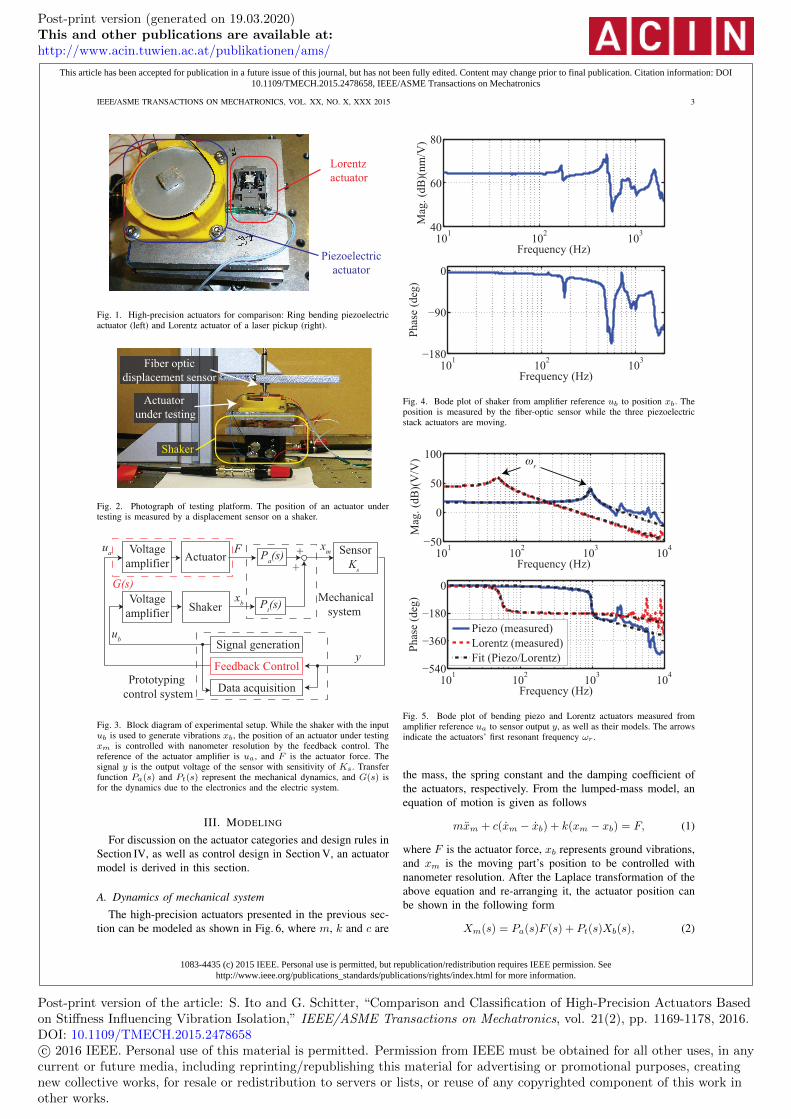
For calibration and analysis of the shaker, the frequencyresponse of the shaker is determined. For this analysis, thesensor position is temporary adjusted to measure xb, and aBode plot is measured from ub to xb. Since the piezoelectricstack actuators of the shaker are mounted without a preload,the frequency of the sine sweep is limited to 2 kHz to avoidpulling forces that may damage the actuators. Fig. 4 shows aBode plot measured by a network analyzer (3562A, HewlettPackard, Palo Alto, USA). From the flat gain below 100 Hz,the sensitivity of the shaker is calculated as 1621 nm/V,which is used to correct measured data as calibration inSection VI. Above 100Hz, the shaker has parasitic dynamics.This dynamics is not mathematically modeled as the shaker isonly used to generate the same disturbances for both actuators,which can be regarded as a coloring of the noise as it mayhappen under real conditions.
The respective frequency responses of the bending piezo andLorentz actuators are also measured by the network analyzer.Fig. 5 shows the measured Bode plot from ua to y for bothactuators. The blue solid line is the response of the bendingpiezo, and its first resonance can be seen at a relatively highfrequency of approximately 990 Hz. In contrast, the Lorentzactuator’s response, represented by the red dashed line, showsits first resonance at a low frequency of 54 Hz. In both cases,the actuators do not obviously excite the parasitic dynamics ofthe shaker (e.g. the resonance at 500 Hz as seen in Fig. 4). Thisis because the actuator base including the 10 mm Aluminumplate is much heavier than the moving part, and the basemovement resulting from the actuator’s counterforce can beignored. The black dash-dot lines in Fig. 5 represent the fittedmodels to be discussed in the next section.
Post-print version (generated on 19.03.2020)This and other publications are available at:http://www.acin.tuwien.ac.at/publikationen/ams/
current or future media, including reprinting/republishing this material for advertising or promotional purposes, creatingnew collective works, for resale or redistribution to servers or lists, or reuse of any copyrighted component of this work inother works.
1083-4435 (c) 2015 IEEE. Personal use is permitted, but republication/redistribution requires IEEE permission. Seehttp://www.ieee.org/publications_standards/publications/rights/index.html for more information.
This article has been accepted for publication in a future issue of this journal, but has not been fully edited. Content may change prior to final publication. Citation information: DOI10.1109/TMECH.2015.2478658, IEEE/ASME Transactions on Mechatronics
Fig. 1. High-precision actuators for comparison: Ring bending piezoelectricactuator (left) and Lorentz actuator of a laser pickup (right).
Fiber optic
displacement sensor
Shaker
Actuator
under testing
Fig. 2. Photograph of testing platform. The position of an actuator undertesting is measured by a displacement sensor on a shaker.
Prototyping
control system
Voltage
amplifierActuator
ShakerMechanical
system
Sensor
Ks
Data acquisition
xm
xb
Fua
Voltage
amplifierP
t(s)
Pa(s)
Feedback Control
Signal generation
+
+
G(s)
ub
y
Fig. 3. Block diagram of experimental setup. While the shaker with the inputub is used to generate vibrations xb, the position of an actuator under testingxm is controlled with nanometer resolution by the feedback control. Thereference of the actuator amplifier is ua, and F is the actuator force. Thesignal y is the output voltage of the sensor with sensitivity of Ks. Transferfunction Pa(s) and Pt(s) represent the mechanical dynamics, and G(s) isfor the dynamics due to the electronics and the electric system.
III. MODELING
For discussion on the actuator categories and design rules inSection IV, as well as control design in Section V, an actuatormodel is derived in this section.
A. Dynamics of mechanical system
The high-precision actuators presented in the previous sec-tion can be modeled as shown in Fig. 6, where m, k and c are
101
102
103
40
60
80
Frequency (Hz)
Mag
. (d
B)(
nm
/V)
101
102
103
−180
−90
0
Frequency (Hz)
Ph
ase
(deg
)Fig. 4. Bode plot of shaker from amplifier reference ub to position xb. Theposition is measured by the fiber-optic sensor while the three piezoelectricstack actuators are moving.
101
102
103
104
−50
0
50
100
Frequency (Hz)
Mag
. (d
B)(
V/V
) ωr
101
102
103
104
−540
−360
−180
0
Frequency (Hz)
Ph
ase
(deg
)
Piezo (measured)
Lorentz (measured)
Fit (Piezo/Lorentz)
Fig. 5. Bode plot of bending piezo and Lorentz actuators measured fromamplifier reference ua to sensor output y, as well as their models. The arrowsindicate the actuators’ first resonant frequency ωr .
the mass, the spring constant and the damping coefficient ofthe actuators, respectively. From the lumped-mass model, anequation of motion is given as follows
mxm + c(xm − xb) + k(xm − xb) = F, (1)
where F is the actuator force, xb represents ground vibrations,and xm is the moving part’s position to be controlled withnanometer resolution. After the Laplace transformation of theabove equation and re-arranging it, the actuator position canbe shown in the following form
Xm(s) = Pa(s)F (s) + Pt(s)Xb(s), (2)
Post-print version (generated on 19.03.2020)This and other publications are available at:http://www.acin.tuwien.ac.at/publikationen/ams/
current or future media, including reprinting/republishing this material for advertising or promotional purposes, creatingnew collective works, for resale or redistribution to servers or lists, or reuse of any copyrighted component of this work inother works.
1083-4435 (c) 2015 IEEE. Personal use is permitted, but republication/redistribution requires IEEE permission. Seehttp://www.ieee.org/publications_standards/publications/rights/index.html for more information.
This article has been accepted for publication in a future issue of this journal, but has not been fully edited. Content may change prior to final publication. Citation information: DOI10.1109/TMECH.2015.2478658, IEEE/ASME Transactions on Mechatronics
Fig. 6. Lumped mass model of precision actuator on testing platform.
using
Pa(s) =Xm(s)
F (s)=
1
ms2 + cs + k, (3)
Pt(s) =Xm(s)
Xb(s)=
cs + k
ms2 + cs + k, (4)
where Xm(s), Xb(s) and F (s) are the Laplace transformationof xm, xb and F , respectively. The transfer function Pt(s) isfrom the actuator base to the moving part position and is thetransmissibility of the system [7].
B. Dynamics of electronics and electrical system
The derived mechanical model (3) is a minimum phasesystem and does not model any delay. Nevertheless, themeasured Bode plot in Fig. 5 shows a delay of approximately20 µs for the Lorentz and 100 µs for the piezo actuator. Sincethe delay is different for each actuator despite the use of thesame sensor, it can be assumed that the actuator amplifierscause the majority of this delay. In order to capture it, thetransfer function to relate the amplifier reference ua withthe actuator force F is given by using the first-order Padeapproximation [3]
G(s) =F (s)
Ua(s)=
1 − τ2 s
1 + τ2 s
KaKf , (5)
where Ua(s) is the Laplace transformation of ua and τ isthe delay, as well as the gain of the respective amplifier Ka.The constant Kf is the force-to-voltage ratio of the respectiveactuator. For the bending piezo, it is approximated by the ratioof the blocking force and the maximum operational voltage,while for the Lorentz actuator it is by the ratio of the motorconstant and the coil resistance.
Nonlinearity of piezos (e.g. hysteresis or creep) [7] can bea problem when they are used in an open-loop control orwhen their control input is utilized (e.g. AFMs). However,when these actuators are used in a closed loop with a positionsensor, such nonlinearity is typically well-compensated by thefeedback controller (cf. [20]). Since the actuators in this paperare compared in a closed loop for vibration isolation, thenonlinearity is not modeled.
The fiber-optic displacement sensor has a bandwidth of100 kHz, which is 10 times higher than the frequency band of
TABLE IIESTIMATED PARAMETERS OF ACTUATOR MODEL
Parameters Piezo Lorentz
g 6.68 158
ζ 0.025 0.083
ωn 2π·995 2π·54.7
τ 100 µs 20 µs
Fig. 5. Even if the sensor may cause a phase lag, it is incorpo-rated into (5). Therefore, the sensor dynamics is treated as aconstant, which is the sensor sensitivity Ks = 0.341 mV/nm.
C. Parameter estimation
Using the introduced models (3) and (5), the transferfunction from ua to y is given as G(s)Pa(s)Ks and can bere-arranged as follows
G(s)Pa(s)Ks =
(g
s2
ω2n
+ 2ζ sωn
+ 1
)(1 − τ
2 s
1 + τ2 s
), (6)
where g is the gain, ζ is the damping ratio, and ωn is theundamped natural frequency [7] given as
g =KsKaKf
k, ζ =
c
2√
km, ωn =
√k
m. (7)
For feedback control design, these parameters are estimated,such that the magnitude and the phase of (6) accord withthose of the measured frequency responses as shown in Fig. 5.The estimated parameters are listed in Table II. Fig. 5 clearlyshows that the model captures the first resonance at 54 Hz and990 Hz of the Lorentz and piezo actuators, respectively. Sincethe delay is also captured well, the model shows a good fit atleast up to 1.5 kHz. Above the frequency, parasitic dynamicscan be seen for both actuators.
IV. ACTUATOR DEFINITION & MODEL-BASED ANALYSIS
After the influence of feedback control on the transmis-sibility is discussed, low-stiffness actuators are defined andanalyzed to derive design rules to construct them in thissection.
A. Transmissibility with feedback control
For the improvement of motion control performance, feed-back control can be used to reject disturbances includingvibrations [8] and to compensate for actuator non-linearity(e.g. creep or hysteresis) [20]. For discussion on the actuatorcategories, a feedback controller C(s) is introduced as shownin Fig. 7, where r and e are position reference and error,respectively. Feedback control influences the transmissibility,and the transmissibility with feedback control can be derivedby substituting F (s) by −G(s)C(s)KsXm(s) in (2) as fol-lows
Xm(s)
Xb(s)=
Pt(s)
1 + Pa(s)G(s)C(s)Ks= Pt(s)S(s), (8)
Post-print version (generated on 19.03.2020)This and other publications are available at:http://www.acin.tuwien.ac.at/publikationen/ams/
current or future media, including reprinting/republishing this material for advertising or promotional purposes, creatingnew collective works, for resale or redistribution to servers or lists, or reuse of any copyrighted component of this work inother works.
1083-4435 (c) 2015 IEEE. Personal use is permitted, but republication/redistribution requires IEEE permission. Seehttp://www.ieee.org/publications_standards/publications/rights/index.html for more information.
This article has been accepted for publication in a future issue of this journal, but has not been fully edited. Content may change prior to final publication. Citation information: DOI10.1109/TMECH.2015.2478658, IEEE/ASME Transactions on Mechatronics
Fig. 7. Control block diagram of high-precision actuator and sensorG(s)Pa(s)Ks with feedback control C(s), where r and e are positionreference and error, respectively.
where S(s) is the sensitivity function of the feedback loop,which is equivalent to the transfer function from r to e.In order to eliminate a steady-state position error, typicallyS(s) has high-pass characteristics with a low gain at lowfrequencies.
B. Actuator definition and analysisAn actuator with good vibration isolation must decouple
the actuator position xm from the vibrations xb within arequired frequency band. Furthermore, as the floor vibrationsmay contain shocks with low and high frequency components,it is desirable that the actuator does not amplify the vibrationstransmitting to xm at any frequencies for high-precision mo-tion control. Since vibration transmission is quantized by thetransmissibility, characterized by high vibration isolation (cf.Table I), a low-stiffness actuator is defined as the ones witha transmissibility that is less than 0 dB for all frequencies.Consequently, high-stiffness actuators are ones that are neitherzero- nor low-stiffness. Therefore, high-stiffness actuators aredefined as ones with a transmissibility that reaches or evenexceeds 0 dB at some parts of the spectrum.
The definition of the low-stiffness actuators can be describedby replacing s by jω in (8) as
∣∣∣∣Xm(jω)
Xb(jω)
∣∣∣∣ = |Pt(jω)S(jω)| < 1, ∀ω. (9)
The sensitivity function S(jω) in positioning systems typicallyhas a magnitude less than 0 dB at low frequencies to track thereference r. At high frequencies, the magnitude is larger than0 dB due to the waterbed effect [7]. In-between |S(jω)| crossesthe 0 dB line at a frequency, which is defined as the unit-gain cross-over frequency of the sensitivity function ωs (i.e.|S(jωs)| = 1). Since |S(jω)| can be 1 or larger for ω ≥ ωs,the magnitude of the transmissibility without control |Pt(jω)|needs to be at least smaller than 1 in the frequency range tosatisfy (9), as formulated in the following necessary condition
|Pt(jω)| < 1, for ω ≥ ωs. (10)
For the passive vibration isolation behavior of Pt(jω), itsmagnitude is less than one for all frequencies larger than
√2ωn
as follows
|Pt(jω)| < 1, for ω >√
2ωn, (11)
where ωn is the undamped natural frequency. The frequency√2ωn is derived by solving |Pt(jω)| = 1. From (11), the
condition of (10) is satisfied only in the frequency range largerthan
√2ωn, resulting in the following requirement to design
a low-stiffness actuator√
2ωn < ωs. (12)
Since ωn is given by√
k/m, the above equation can berewritten as
k < mω2s/2. (13)
Although the discussion above holds with any dampingcoefficient c, it is typically far less than the critical dampingfor high-precision actuators (i.e. ζ ≪ 1). For vibration isola-tion, this characteristics is often favorable because a damperintroduces dynamic coupling at high frequencies due to thezero in the transmissibility (4) [7]. With such a low dampingcoefficient, ωn can be approximated by the resonant frequencyωr, and the following design rule is also applicable in practice
√2ωr < ωs. (14)
The left hand side of this equation is the lowest frequencyof the passive vibration isolation. Similarly, the right can beregarded as the highest frequency of the disturbance rejec-tion by the feedback control (i.e. active vibration isolation).Therefore, (14) can be interpreted that low-stiffness actuatorsare realized by a combination of active and passive vibrationisolation in the frequency domain, as illustrated in Fig. 8(a). Inother words, low-stiffness actuators achieve smooth transitionfrom the active to the passive vibration isolation. In contrast,high-stiffness actuators can have a gap between the passive andactive vibration isolation in the frequency domain as shown inFig. 8(b). Thus, the vibrations from the base are even amplifiedon the moving part in a certain frequency band.
Required control bandwidth of actuators can also be dis-cussed with (14). Since it is typically higher than ωs [21], thecontrol bandwidth of low-stiffness actuators has to be higherthan the resonant frequency ωr. This requirement implies thatsome feedback controllers are not suitable for low-stiffnessactuators, particularly I, PI and PII controllers, because ωr
restricts the control bandwidth with these controllers forstability [18], [22]. In contrast, there is no requirement on thecontrol bandwidth to construct high stiffness actuators, and itcan be less than ωr dependent on the control design.
Note that the discussion in this section is applicable to anyfeedback control described by C(s), since its structure hasnot been specified. For the experiments in this paper, C(s) isdesigned by using H∞ control synthesis in the next section.
V. CONTROL DESIGN
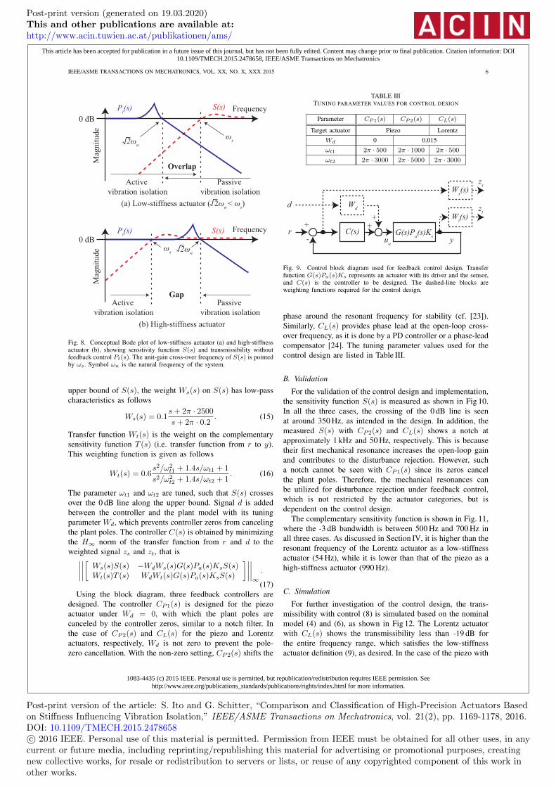
For a fair comparison of the actuators presented in Sec-tion II, feedback controllers are individually designed, suchthat their cross-over frequency ωs is about 350 Hz. Withthis frequency, the Lorentz and piezo actuators become low-stiffness and high-stiffness actuators, respectively according to(14) because of the difference in the first resonant frequency(cf. Fig. 5). Because the upper bound of the sensitivity functionS(s) can be shaped with proper weights, H∞ control synthesis[21] is selected for the feedback control design.
A. H∞ control synthesis
Fig. 9 shows a control block diagram with weighting func-tions for the control synthesis. Because its inverse is the
Post-print version (generated on 19.03.2020)This and other publications are available at:http://www.acin.tuwien.ac.at/publikationen/ams/
current or future media, including reprinting/republishing this material for advertising or promotional purposes, creatingnew collective works, for resale or redistribution to servers or lists, or reuse of any copyrighted component of this work inother works.
1083-4435 (c) 2015 IEEE. Personal use is permitted, but republication/redistribution requires IEEE permission. Seehttp://www.ieee.org/publications_standards/publications/rights/index.html for more information.
This article has been accepted for publication in a future issue of this journal, but has not been fully edited. Content may change prior to final publication. Citation information: DOI10.1109/TMECH.2015.2478658, IEEE/ASME Transactions on Mechatronics
Fig. 8. Conceptual Bode plot of low-stiffness actuator (a) and high-stiffnessactuator (b), showing sensitivity function S(s) and transmissibility withoutfeedback control Pt(s). The unit-gain cross-over frequency of S(s) is pointedby ωs. Symbol ωn is the natural frequency of the system.
upper bound of S(s), the weight Ws(s) on S(s) has low-passcharacteristics as follows
Ws(s) = 0.1s + 2π · 2500
s + 2π · 0.2. (15)
Transfer function Wt(s) is the weight on the complementarysensitivity function T (s) (i.e. transfer function from r to y).This weighting function is given as follows
Wt(s) = 0.6s2/ω2
t1 + 1.4s/ωt1 + 1
s2/ω2t2 + 1.4s/ωt2 + 1
. (16)
The parameter ωt1 and ωt2 are tuned, such that S(s) crossesover the 0 dB line along the upper bound. Signal d is addedbetween the controller and the plant model with its tuningparameter Wd, which prevents controller zeros from cancelingthe plant poles. The controller C(s) is obtained by minimizingthe H∞ norm of the transfer function from r and d to theweighted signal zs and zt, that is∣∣∣∣∣∣∣∣[
Ws(s)S(s) −WdWs(s)G(s)Pa(s)KsS(s)Wt(s)T (s) WdWt(s)G(s)Pa(s)KsS(s)
]∣∣∣∣∣∣∣∣∞
.
(17)Using the block diagram, three feedback controllers are
designed. The controller CP1(s) is designed for the piezoactuator under Wd = 0, with which the plant poles arecanceled by the controller zeros, similar to a notch filter. Inthe case of CP2(s) and CL(s) for the piezo and Lorentzactuators, respectively, Wd is not zero to prevent the pole-zero cancellation. With the non-zero setting, CP2(s) shifts the
TABLE IIITUNING PARAMETER VALUES FOR CONTROL DESIGN
Parameter CP1(s) CP2(s) CL(s)
Target actuator Piezo Lorentz
Wd 0 0.015
ωt1 2π · 500 2π · 1000 2π · 500
ωt2 2π · 3000 2π · 5000 2π · 3000
d
+
-r C(s)
++
Wt(s)
yG(s)P
a(s)K
su
a
Ws(s)
Wd
zs
zt
Fig. 9. Control block diagram used for feedback control design. Transferfunction G(s)Pa(s)Ks represents an actuator with its driver and the sensor,and C(s) is the controller to be designed. The dashed-line blocks areweighting functions required for the control design.
phase around the resonant frequency for stability (cf. [23]).Similarly, CL(s) provides phase lead at the open-loop cross-over frequency, as it is done by a PD controller or a phase-leadcompensator [24]. The tuning parameter values used for thecontrol design are listed in Table III.
B. Validation
For the validation of the control design and implementation,the sensitivity function S(s) is measured as shown in Fig 10.In all the three cases, the crossing of the 0 dB line is seenat around 350 Hz, as intended in the design. In addition, themeasured S(s) with CP2(s) and CL(s) shows a notch atapproximately 1 kHz and 50 Hz, respectively. This is becausetheir first mechanical resonance increases the open-loop gainand contributes to the disturbance rejection. However, sucha notch cannot be seen with CP1(s) since its zeros cancelthe plant poles. Therefore, the mechanical resonances canbe utilized for disturbance rejection under feedback control,which is not restricted by the actuator categories, but isdependent on the control design.
The complementary sensitivity function is shown in Fig. 11,where the -3 dB bandwidth is between 500 Hz and 700 Hz inall three cases. As discussed in Section IV, it is higher than theresonant frequency of the Lorentz actuator as a low-stiffnessactuator (54 Hz), while it is lower than that of the piezo as ahigh-stiffness actuator (990 Hz).
C. Simulation
For further investigation of the control design, the trans-missibility with control (8) is simulated based on the nominalmodel (4) and (6), as shown in Fig 12. The Lorentz actuatorwith CL(s) shows the transmissibility less than -19 dB forthe entire frequency range, which satisfies the low-stiffnessactuator definition (9), as desired. In the case of the piezo with
Post-print version (generated on 19.03.2020)This and other publications are available at:http://www.acin.tuwien.ac.at/publikationen/ams/
current or future media, including reprinting/republishing this material for advertising or promotional purposes, creatingnew collective works, for resale or redistribution to servers or lists, or reuse of any copyrighted component of this work inother works.
1083-4435 (c) 2015 IEEE. Personal use is permitted, but republication/redistribution requires IEEE permission. Seehttp://www.ieee.org/publications_standards/publications/rights/index.html for more information.
This article has been accepted for publication in a future issue of this journal, but has not been fully edited. Content may change prior to final publication. Citation information: DOI10.1109/TMECH.2015.2478658, IEEE/ASME Transactions on Mechatronics
Fig. 10. Sensitivity function S(s) measured for validation of control designand implementation with inverse of weighting function Ws(s). ControllerCP1(s) and CP2(s) are implemented for the piezo actuator, while CL(s)is for the Lorentz actuator. Symbol ωs indicates the corresponding unit-gaincross-over frequencies.
101
102
103
104
−40
−20
0
Frequency (Hz)
Mag
nit
ude
(dB
)
101
102
103
104
−900
−720
−540
−360
−180
0
Frequency (Hz)
Ph
ase
(deg
)
CP1
CP2
CL
Fig. 11. Complementary sensitivity function T (s) measured for validationof control design and implementation. Controller CP1(s) and CP2(s) areimplemented for the piezo actuator, while CL(s) is for the Lorentz actuator.
CP1(s) and CP2(s), it behaves as a high-stiffness actuator,showing the transmissibility larger than 0 dB approximatelybetween 300 Hz and 1.5 kHz.
For investigation in the time domain, response to a stepin the actuator base position xb is simulated, since stepscontain high frequency components. The step height is setat 160 nm, which is almost the same stimulus as the experi-ments in Section VI. Fig 13(a)(b) shows the simulated actuatorposition xm. The maximum value of xm is 245 nm and216 nm at approximately 0.4 ms for the piezo with CP1(s)and CP2(s), respectively, and particularly the response withCP1(s) shows a long lasting oscillation due to the excitedmechanical resonance at about 1 kHz. In the case of theLorentz actuator with CL(s), the maximum value of xm isonly 9.07 nm, demonstrating good vibration isolation of a low-stiffness actuator. For the step input, the control input ua (i.e.reference to the actuator amplifier) is also simulated as shownin Fig 13(c)(d). For this simulation, a transfer function from
100
101
102
103
104
−60
−40
−20
0
20
40
Frequency (Hz)
Mag
nit
ude
(dB
)
CP1
CP2
CL
Fig. 12. Simulated transmissibility of bending piezo with designed feedbackcontroller CP1(s) and CP2(s), as well as Lorentz actuator with CL(s).
xb to ua is derived from Fig. 7 and (2) as follows
Ua(s)
Xb(s)= −KsC(s)Pt(s)S(s). (18)
To compensate for the step of xb, the simulated control inputconverges to a certain value, which is different for eachactuator, due to the difference in the actuator gain g of Table II.
VI. EXPERIMENTS
In order to validate the design rule, experiments in thefrequency and time domain are presented. The measured datain this section is corrected with the sensor sensitivity Ks andthe shaker sensitivity of 1621 nm/V as a part of the calibration.However, the shaker dynamics shown in Fig. 4 is not removedfrom the data, resembling an actual case how it may occurin a real system and demonstrating that the design rule (14)is applicable to practical high-precision mechatronic systems,where such unwanted parasitic dynamics are often inevitablyoccur.
A. Frequency response
The transmissibility of the actuators without feedbackcontrol is shown in Fig 14. The magnitude of the Lorentzactuator crosses the 0 dB line at 72 Hz, which is close to√
2ωn(≈76 Hz) as discussed with (11). In the case of thepiezo, however, such clear trend cannot be seen due to theparasitic dynamics of the actuator and the shaker. Among theshaker resonances in Fig. 4, the largest at 500 Hz can be clearlyobserved with both actuators.
Fig. 15 shows the transmissibility of the actuators withthe designed controllers, where the 2 kHz bandwidth limitdue to the shaker determines the maximum frequency. TheLorentz actuator achieves the transmissibility of -40 dB at alow frequency of 10 Hz for good vibration isolation. Whilethe experimental results show trends similar to the simula-tion in Fig. 12 at low frequencies, the magnitude in Fig. 15increases at 546 Hz and 834 Hz due to the parasitic dynamics.Nevertheless, the Lorentz actuator achieves the transmissibilityof less than -10 dB for the entire frequency range, satisfyingthe definition of the low-stiffness actuators (9). The trendchange of the transmissibility at approximately 70 Hz is due tothe smooth transition from the active to the passive vibrationisolation, as discussed with Fig. 8(a).
Post-print version (generated on 19.03.2020)This and other publications are available at:http://www.acin.tuwien.ac.at/publikationen/ams/
current or future media, including reprinting/republishing this material for advertising or promotional purposes, creatingnew collective works, for resale or redistribution to servers or lists, or reuse of any copyrighted component of this work inother works.
1083-4435 (c) 2015 IEEE. Personal use is permitted, but republication/redistribution requires IEEE permission. Seehttp://www.ieee.org/publications_standards/publications/rights/index.html for more information.
This article has been accepted for publication in a future issue of this journal, but has not been fully edited. Content may change prior to final publication. Citation information: DOI10.1109/TMECH.2015.2478658, IEEE/ASME Transactions on Mechatronics
Fig. 13. Simulated response to a 160 nm step in actuator base position xb:(a) position xm of piezo actuator with CP1(s) and CP2(s), (b) positionxm of Lorentz actuator with CL(s), (c) control input ua from CP1(s) andCP2(s), and (d) control input ua from CL(s).
The bending piezo in Fig. 15 also shows good vibrationisolation at a low frequency of 10 Hz, where the transmis-sibility is about -33 dB. However, it amplifies the vibrationsdue to the transmissibility larger than 0 dB approximatelybetween 300 Hz and 1.6 kHz, because neither the active northe passive vibration isolation is effective in the band (cf.Fig 8(b)). Although the controller CP2(s) trims the peak atthe resonant frequency of 990 Hz, the magnitude still exceeds0 dB.
B. Step response
As a demonstration in the time domain, since it con-tains high frequency components, a step of 100 mV, whichcorresponds to 162 nm, is given to the shaker amplifier tomove the shaker in the direction of −xb (i.e. expandingthe piezoelectric stack actuators). During the experiment, the
101
102
103
−60
−40
−20
0
20
40
Frequency (Hz)
Mag
nit
ud
e (d
B)
101
102
103
−1080
−900
−720
−540
−360
−180
0
Frequency (Hz)
Ph
ase
(deg
)
Piezo
Lorentz
Fig. 14. Measured transmissibility of the bending piezo and the Lorentzactuator without feedback control.
101
102
103
−60
−40
−20
0
20
40
Frequency (Hz)
Mag
nit
ud
e (d
B)
CP1
CP2
CL
Fig. 15. Measured transmissibility of bending piezo with designed feedbackcontroller CP1(s) and CP2(s), as well as Lorentz actuator with CL(s).
feedback control is active to keep the respective actuatorposition xm at a static position, and the position error e isrecorded as shown in Fig. 16. The error of the bending piezoswings between ± 200 nm, because the step input excites themechanical resonances, as it can also be seen in the powerspectral density shown in Fig. 16(d). In the case of the Lorentzactuator, however, the error is suppressed within a range of± 10 nm, since the vibration isolation is effective for the entirefrequency range as a low-stiffness actuator (cf. Fig. 15). Incomparison with the simulation in Fig. 13, Fig. 16(d) showsthat the step input excites unmodeled dynamics, such as theshaker’s resonance at 500 Hz. Nevertheless, Fig. 16(c) showsa small position error of the Lorentz actuator, demonstratinggood vibration isolation as a low-stiffness actuator.
VII. DISCUSSION
In Section IV low-stiffness actuators have been defined asones that reject disturbances from the base for the entire fre-quency range, and high-stiffness actuators are neither zero- norlow-stiffness actuators. From the definition, the spring constantrequired to construct low-stiffness actuators have been derivedin (13) as a design rule. Since its upper bound can be regarded
Post-print version (generated on 19.03.2020)This and other publications are available at:http://www.acin.tuwien.ac.at/publikationen/ams/
current or future media, including reprinting/republishing this material for advertising or promotional purposes, creatingnew collective works, for resale or redistribution to servers or lists, or reuse of any copyrighted component of this work inother works.
1083-4435 (c) 2015 IEEE. Personal use is permitted, but republication/redistribution requires IEEE permission. Seehttp://www.ieee.org/publications_standards/publications/rights/index.html for more information.
This article has been accepted for publication in a future issue of this journal, but has not been fully edited. Content may change prior to final publication. Citation information: DOI10.1109/TMECH.2015.2478658, IEEE/ASME Transactions on Mechatronics
Fig. 16. Measured position error e during positioning at a static point. Step-like disturbances of approximately 160 nm are applied to the actuator basexb at 0.01 s by using the shaker. Plot (a) and (b) show the response of thebending piezo controlled by CP1(s) and CP2(s), respectively, and (c) showsthe response of the Lorentz actuator controlled by CL(s). The last plot (d)is the power spectral density of the position error.
as the border between low- and high- stiffness actuators, thespring constant is related to the actuator categories as shownin Table IV.
The stiffness requirement for low-stiffness actuators canbe rephrased in the frequency domain as: ”the cross-overfrequency of the sensitivity function of the feedback-controlledsystem must be larger than the product of
√2 and the resonant
frequency ωr of the uncontrolled system (cf. (14))”. Whereasthe resonant frequency ωr can be a target value in themechanical design (e.g. by using finite element analysis), thesensitivity function is utilized in the control design, specifyingrequirements on the electronics for control implementationas well as on power electronics for driving the actuator.Therefore, the design rule to construct low-stiffness actuators
TABLE IVRELATION OF SPRING CONSTANT AND ACTUATOR CATEGORIES USING
TRANSMISSIBILITY WITH FEEDBACK CONTROL Tr(jω) AND CROSS-OVERFREQUENCY OF SENSITIVITY FUNCTION ωs
Categories Definition Spring constant
Zero-stiffness No mechanical connection k = 0
Low-stiffness |Tr(jω)| <1 0 < k < mω2s/2
for all frequencies ω
High-stiffness |Tr(jω)| ≥1 mω2s/2 ≤ k
at certain frequencies ω
can be regarded as a link between the mechanical design andthe control design in the development of mechatronic systems.In each design phase sufficient margins need to be added tothe design rule, since it is derived as a necessary condition.
Although the proposed design rule (14) does not specify theactuation principle of a low-stiffness actuator, satisfying it isdifficult with piezos for vibration isolation in practice. This istypically because their first resonant frequency ωr is too closeto other resonant frequencies to ensure closed-loop stabilityfor (14) (cf. Fig. 5). In contrast, the frequency band betweenthe first and the other resonances of Lorentz actuators can bebroad by design (cf. Fig. 5), making them more suitable toconstruct a low-stiffness actuator.
The proposed design rule (14) can be used in high-precisionapplications. An example is AFMs, where the probe is movedby a Lorentz or piezo actuator [2], [25]. For imaging, AFMsare typically mounted on an external vibration isolator, such asan optical table requiring an air compressor. By using a low-stiffness actuator satisfying (14) to move the probe, vibrationisolation can be integrated in an AFM, instead of using a bulkyexternal vibration isolator. Very first results of an AFM usinglow-stiffness actuators for vibration isolation can be found in[26]. In such a practical system, an application system (e.g.an AFM probe) is mounted as a part of the low-stiffnessactuator’s moving part. To prevent its internal modes fromlimiting the control bandwidth, the application system needsto be sufficiently rigid.
Unlike the ideal damped-mass-spring model used in thederivation of the rule, model uncertainty exits, such as the par-asitic dynamics of the shaker. Nevertheless, as experimentallyvalidated in Section VI, a precision actuator can be compactand have good vibration isolation properties for the entirefrequency range by satisfying the proposed design rule.
VIII. CONCLUSION
This paper compares the vibration isolation properties oflow-stiffness and high-stiffness actuated positioning systems.A Lorentz actuated and piezoelectrically actuated vibrationisolation systems are compared by using the same controlobjectives for designing and implementing H∞ feedbackcontrollers for both systems. These systems are eventuallyexperimentally validated. From the system analysis, a classifi-cation and design guidelines are derived for selecting the firstresonance of the actuator (i.e. stiffness) and the correspondingdisturbance-rejection bandwidth.
Post-print version (generated on 19.03.2020)This and other publications are available at:http://www.acin.tuwien.ac.at/publikationen/ams/
current or future media, including reprinting/republishing this material for advertising or promotional purposes, creatingnew collective works, for resale or redistribution to servers or lists, or reuse of any copyrighted component of this work inother works.
1083-4435 (c) 2015 IEEE. Personal use is permitted, but republication/redistribution requires IEEE permission. Seehttp://www.ieee.org/publications_standards/publications/rights/index.html for more information.
This article has been accepted for publication in a future issue of this journal, but has not been fully edited. Content may change prior to final publication. Citation information: DOI10.1109/TMECH.2015.2478658, IEEE/ASME Transactions on Mechatronics
Low-stiffness actuators are defined as a closed-loop systemwith an actively controlled transmissibility less than 0 dBfor the entire frequency range. Forming a clear border withhigh-stiffness actuators, the definition leads to a design ruleof low-stiffness actuators that the cross-over frequency ofthe closed-loop sensitivity function must be larger than
√2
times the first resonant frequency of the uncontrolled system.Under this condition, an actuator is able to achieve smoothtransition from the active to the passive vibration isolation inthe frequency domain. In contrast, systems with high-stiffnessactuators, defined as neither zero- nor low-stiffness actuators,even amplify the vibrations in the gap between the active andpassive vibration isolation.
REFERENCES
[1] H. Butler, “Position control in lithographic equipment,” IEEE ControlSystems Magazine, vol. 31, no. 5, pp. 28 –47, 2011.
[2] P. Eaton and P. West, Atomic Force Microscopy. Oxford UniversityPress, 2010.
[3] T. Yamaguchi, M. Hirata, and C. Pang, High-Speed Precision MotionControl. Taylor & Francis, 2011.
[4] T. Atsumi and W. C. Messner, “Compensating for ZOH-induced residualvibrations in head-positioning control of hard disk drives,” IEEE/ASMETransactions on Mechatronics, vol. 19, no. 1, pp. 258–268, 2014.
[5] J.-H. Lee and K.-J. Kim, “A method of transmissibility design for dual-chamber pneumatic vibration isolator,” Journal of Sound and Vibration,vol. 323, no. 12, pp. 67 – 92, 2009.
[6] K.-S. Park, S. Lim, Y.-P. Park, Y.-B. Chang, and N.-C. Park, “Shockand vibration isolation of laptop hard disk drive using rubber mount,”Microsystem Technologies, vol. 18, pp. 1559–1566, 2012.
[7] R. Munnig Schmidt, G. Schitter, A. Rankers, and J. van Eijk, The Designof High Performance Mechatronics, 2nd ed. Delft University Press,2014.
[8] S. Ito, J. Steininger, and G. Schitter, “Low-stiffness dual stage actuatorfor long rage positioning with nanometer resolution (In press),” Mecha-tronics, 2015.
[9] Y.-M. Choi and D.-G. Gweon, “A high-precision dual-servo stage usinghalbach linear active magnetic bearings,” IEEE/ASME Transactions onMechatronics, vol. 16, no. 5, pp. 925–931, Oct 2011.
[10] B. Hou, J. Gao, and Y. Zhou, “The development of an ultra-precisiondual-stage based on a master-slave control system,” in International Con-ference on Computer Distributed Control and Intelligent EnvironmentalMonitoring, March 2012, pp. 727 –730.
[11] M.-G. Song, Y.-K. Kim, N.-C. Park, J. Yoo, Y.-P. Park, N. Onagi, andG. Akanuma, “Design of moving magnet type pickup actuator usinginserted coil,” Microsystem Technologies, vol. 15, pp. 1719–1728, 2009.
[12] D.-J. Lee, M.-G. Song, C. Kim, N.-C. Park, Y.-P. Park, N. Onagi, andG. Akanuma, “Improvement of dynamic characteristics for symmetric-type slim optical pickup actuator by changing coil shape,” IEEE Trans-actions on Magnetics, vol. 43, no. 2, pp. 808–810, Feb 2007.
[13] A. H. Chaghajerdi, “Sensing and control in optical drives,” IEEE ControlSystems Magazine, vol. 28, no. 3, pp. 23 –29, 2008.
[14] M. Heertjes and G. Leenknegt, “Switching control in blu-ray diskdrives,” Mechatronics, vol. 20, no. 4, pp. 453 – 463, 2010.
[15] Y. K. Yong, S. O. R. Moheimani, B. J. Kenton, and K. K. Leang, “Invitedreview article: High-speed flexure-guided nanopositioning: Mechanicaldesign and control issues,” Review of Scientific Instruments, vol. 83,no. 12, p. 121101, 2012.
[16] Y. K. Yong, B. Bhikkaji, and S. O. R. Moheimani, “Design, modeling,and FPAA-based control of a high-speed atomic force microscopenanopositioner,” IEEE/ASME Transactions on Mechatronics, vol. 18,no. 3, pp. 1060–1071, June 2013.
[17] G. Schitter, K. J. Astrom, B. E. DeMartini, P. J. Thurner, K. L. Turner,and P. K. Hansma, “Design and modeling of a high-speed afm-scanner,”IEEE Transactions on Control Systems Technology, vol. 15, no. 5, pp.906 –915, 2007.
[18] A. J. Fleming, “Nanopositioning system with force feedback for high-performance tracking and vibration control,” IEEE/ASME Transactionson Mechatronics, vol. 15, no. 3, pp. 433–447, June 2010.
[19] G. Schitter, P. J. Thurner, and P. K. Hansma, “Design and input-shapingcontrol of a novel scanner for high-speed atomic force microscopy,”Mechatronics, vol. 18, no. 56, pp. 282 – 288, 2008.
[20] Y. Shan, J. E. Speich, and K. K. Leang, “Low-cost IR reflective sen-sors for submicrolevel position measurement and control,” IEEE/ASMETransactions on Mechatronics, vol. 13, no. 6, pp. 700–709, 2008.
[21] S. Skogestad and I. Postlethwaite, Multivariable Feedback Control.John Wiley, 2005.
[22] D. Y. Abramovitch, S. B. Andersson, L. Y. Pao, and G. Schitter, “Atutorial on the mechanisms, dynamics, and control of atomic forcemicroscopes,” in American Control Conference, July 2007, pp. 3488–3502.
[23] M. Kobayashi, S. Nakagawa, and S. Nakamura, “A phase-stabilizedservo controller for dual-stage actuators in hard disk drives,” IEEETransactions on Magnetics, vol. 39, no. 2, pp. 844–850, Mar 2003.
[24] W. C. Messner, M. D. Bedillion, L. Xia, and D. C. Karns, “Lead andlag compensators with complex poles and zeros,” IEEE Control SystemsMagazine, vol. 27, no. 1, pp. 44–54, Feb 2007.
[25] H. Barnard, C. Randall, D. Bridges, and P. K. Hansma, “The long rangevoice coil atomic force microscope,” Review of Scientific Instruments,vol. 83, no. 2, pp. –, 2012.
[26] S. Ito, D. Neyer, S. Pirker, J. Steininger, and G. Schitter, “Atomicforce microscopy using voice coil actuators for vibration isolation,” inIEEE/ASME International Conference on Advanced Intelligent Mecha-tronics, July 2015, pp. 470–475.
Shingo Ito received his M.A.Sc. degree in mechan-ical and industrial engineering from the Universityof Toronto, ON, Canada, in 2007. From 2007 to2010, he worked as an engineer in the field ofmotion control at Yaskawa Electric Corporation,Iruma, Japan.
Currently he works toward his Ph.D. degree at theAutomation and Control Institute (ACIN), the Vi-enna University of Technology, Austria. His researchinterest includes design and control of mechatronicsystems and high-precision motion control.
Georg Schitter (SM’11) is Professor at the Au-tomation and Control Institute (ACIN) of the ViennaUniversity of Technology. He received an MSc. inElectrical Engineering from TU Graz, Austria (2000)and his PhD degree from ETH Zurich, Switzerland(2004).
His primary research interests are on high-performance mechatronic systems and multidisci-plinary systems integration, particularly for precisionengineering applications in the high-tech industry,scientific instrumentation, and mechatronic imaging
systems, such as scanning probe microscopy, adaptive optics, and lithographysystems for semiconductor industry.
He serves as Associate Editor for the IEEE/ASME Transactions on Mecha-tronics (2010-2014) as well as for the IFAC Journals Control EngineeringPractice and IFAC Mechatronics.
Post-print version (generated on 19.03.2020)This and other publications are available at:http://www.acin.tuwien.ac.at/publikationen/ams/
current or future media, including reprinting/republishing this material for advertising or promotional purposes, creatingnew collective works, for resale or redistribution to servers or lists, or reuse of any copyrighted component of this work inother works.