60
N0C902A Rev. 2 Sept. 14, 2010 IER 560 COMBO PRINTER User Guide N0C902A

N0C902A Rev. 2 Sept. 14, 2010
IER 560 COMBO PRINTER
User Guide N0C902A

IER 560 COMBO PRINTER User Guide
Page 2 N0C902A Rev. 2 Sept. 14, 2010
Ce document est la propriété d’IER et ne doit pas être reproduit ou communiqué sans autorisation écrite. This document is the property of IER and may not be reproduced or communicated
without prior written authorization
IER SIEGE - HEADQUARTERS
IER S.A. 3, rue Salomon de Rothschild 92156 SURESNES CEDEX France Tel. +33 (0)1 41 38 60 00 Fax +33 (0)1 41 38 62 75
IER DANS LE MONDE - IER WORLDWIDE
CHINA
IER Shanghai Kuen Yang Plaza #1101 798 Zhao Jia Bang Road SHANGHAI 200030 P.R.C. Phone: +86 (21) 6473 6792 Fax: +86 (21) 6473 6806
UNITED ARAB EMIRATES
IER Dubai PO Box 37585 DUBAI Phone: +971 4 347 67 20 Fax: +971 4 347 67 03
GERMANY
IER GmbH Wilhelm-Heinichen-Ring 4 29227 Celle Phone: +49 (0) 5141/980 89 14 Fax: +49 (0) 5141/980 89 20
UNITED KINGDOM
IER Ltd Unit 4 & 5, Lakeside Industrial Estate Colnbrook-by-Pass Colnbrook, Berkshire, SL3 0EE Phone: +44 (0)175356 1400 Fax: +44 (0)175356 1410
SINGAPORE
IER PTE Ltd 120 Lower Delta Road #14-13/16 Cendex Centre SINGAPORE 169208 Phone: +65 6276 6966 Fax: +65 6271 5563
UNITED STATES
IER Inc. Addison 16415 Addison Road Suite 160 ADDISON, TEXAS, TX 75001 Phone: +1 (972) 991 2292 Fax: +1 (972) 991 1044 Toll free: 1-800 624 8538
IER Inc. Belton
1000 Industrial Park Road BELTON, TX 76513 Phone: +1 (254) 933 5000 Fax: +1 (254) 933 5050
SPAIN
IER Impresoras Especializadas, S.L. C/ Torre de Don Miguel, 23 E-28031 – MADRID Phone: +34 91 535 89 75 Fax: +34 91 535 89 76

IER 560 COMBO PRINTER User Guide
Page 3 N0C902A Rev. 2
Sept. 14, 2010
Ce document est la propriété d’IER et ne doit pas être reproduit ou communiqué sans autorisation écrite. This document is the property of IER and may not be reproduced or communicated
without prior written authorization
NOTICE
WARNING
THIS PRODUCT COMES WITH A LITHIUM BATTERY. BATTERY REPLACEMENT MUST IMPERATIVELY BE PERFORMED BY QUALIFIED MAINTENANCE PERSONNEL. MOREOVER, ONLY IER APPROVED MODELS MAY BE USED.
WARNING
DANGER OF EXPLOSION IF BATTERY IS INCORRECTLY REPLACED.
REPLACE ONLY WITH THE SAME OR EQUIVALENT TYPE RECOMMENDED BY THE MANUFACTURER.
DISPOSE OF USED BATTERIES ACCORDING TO THE MANUFACTURER’S INSTRUCTIONS.
The United States Federal Communications Commission (in 47 CFR 15.105) has specified that the following notice be brought to the attention of users of this product.
NOTE: This equipment has been tested and found to comply with the limits for a Class B digital device, pursuant to Part 15 of the FCC Rules. These limits are designed to provide reasonable protection against harmful interference in a residential installation. This equipment generates, uses and can radiate radio frequency energy and, if not installed and used in accordance with the instructions, may cause harmful interference to radio communications. However, there is no guarantee that interference will not occur in a particular installation.
If this equipment does cause harmful interference to radio or television reception, which can be determined by turning the equipment off and on, the user is encouraged to try to correct the interference by one or more of the following measures:
Reorient or relocate the receiving antenna
Increase the separation between the equipment and receiver
Connect the equipment into an outlet on a circuit different from that to which the receiver is connected
Consult the dealer or an experienced radio/TV technician for help.
In accordance with FCC requirements, changes or modifications not expressly approved by IER could void the user's authority to operate this product.
Use of a shielded cable is required to comply within Class B limits of Part 15 of FCC Rules.

IER 560 COMBO PRINTER User Guide
Page 4 N0C902A Rev. 2 Sept. 14, 2010
Ce document est la propriété d’IER et ne doit pas être reproduit ou communiqué sans autorisation écrite. This document is the property of IER and may not be reproduced or communicated
without prior written authorization
NORWAY: This product is also designed for IT power distribution system with phase-to-phase voltage 230V.
NORWAY – SWEDEN – FINLAND: Apparaten skall anslutas till jordat uttag när den ansluts till ett nätverk.
WARNING
THIS APPLIANCE MUST BE GROUNDED.
THIS PRODUCT MUST EXCLUSIVELY BE CONNECTED TO AN ELECTRICAL CIRCUIT THAT IS:
PROVIDED WITH A GROUND FAULT CIRCUIT INTERRUPTER (GFCI) COMPLYING WITH IEC 364 AND NFC15-100 REGULATIONS, AND
CONFORMING WITH THE VOLTAGE CHARACTERISTICS SPECIFIED BY THE NF EN 50160 STANDARD.
The cover(s), door(s) and/or drawer(s) of this product is (are) intended for occasional use and must be normally closed.
The information and specifications contained in this document are subject to change without prior notice.
Translated from French - IER Documentation Department
This document contains proprietary information of IER. It may not be reproduced or communicated without prior written authorization of IER. It is intended solely for the use
of the product described herein, to the exclusion of any other usage.
It is provided as is, for information purposes only, without any warranty of any kind, including any warranty of fitness or a particular purpose, and may be modified by IER at
any time.
The warranty shall be null and void in case of use of any spare part, special tool or consumable not expressly approved in writing by IER and in the event of attempted repair or servicing of the
machines by persons lacking the requisite technical qualifications.

IER 560 COMBO PRINTER User Guide
Page 5 N0C902A Rev. 2
Sept. 14, 2010
Ce document est la propriété d’IER et ne doit pas être reproduit ou communiqué sans autorisation écrite. This document is the property of IER and may not be reproduced or communicated
without prior written authorization
In compliance with the European Directive 2002/96/CE relative to the management of Waste Electrical and Electronic Equipment (WEEE) implemented as of August 13, 2005, this product may not be disposed of with regular household waste. All products concerned by this directive are marked with the above symbol.
The end owner of this product is responsible for either:
Transferring the product to an authorized treatment facility where the product components, recognized to present a hazard to the environment and/or public health, will be recycled and recovered properly, or
Consulting with the manufacturer for appropriate product waste management according to the terms of the manufacturer.

IER 560 COMBO PRINTER User Guide
Page 6 N0C902A Rev. 2 Sept. 14, 2010
Ce document est la propriété d’IER et ne doit pas être reproduit ou communiqué sans autorisation écrite. This document is the property of IER and may not be reproduced or communicated
without prior written authorization
Table of Contents
1 OVERVIEW..................................................................................................... 8
1.1. PACKAGE CONTENTS ........................................................................... 8 1.2. INTRODUCTION TO THE PRINTER ...................................................... 9 1.3. PRINTER DIMENSIONS ....................................................................... 11 1.4. OPENING AND CLOSING THE PRINTER COVER .............................. 14
1.4.1. Preliminary Information .................................................................. 14 1.5. OPENING AND CLOSING THE CUTTER/BURSTER MODULE .......... 16
1.5.1. Preliminary Information .................................................................. 16 1.6. PRINTER DESCRIPTION ..................................................................... 18
1.6.1. Exterior Front View ......................................................................... 18 1.6.2. Exterior Rear View ......................................................................... 22 1.6.3. Interior View of the Printer .............................................................. 24
2 CONNECTING THE PRINTER AND POWER-UP ....................................... 26
2.1. CONNECTING THE PRINTER .............................................................. 26 2.1.1. Procedure for Connecting the Printer ............................................. 26
2.2. POWERING UP THE PRINTER ............................................................ 30 2.2.1. Powering Up the Printer ................................................................. 30 2.2.2. Powering Down the Printer ............................................................ 31
3 INSTALLING AND LOADING THE MEDIA ................................................. 32
3.1. ATB MEDIA ........................................................................................... 32 3.1.1. Installation of Blank Media ............................................................. 32 3.1.2. Loading of Blank ATB Media into the Printer ................................. 36
3.2. BAG TAG MEDIA .................................................................................... 38 3.2.1. Installation of Blank Media ............................................................. 38 3.2.2. Loading of Blank Bag Tag Media into the Printer .......................... 40
3.3. MEDIA REMOVAL ................................................................................. 42 3.3.1. Procedure ....................................................................................... 42

IER 560 COMBO PRINTER User Guide
Page 7 N0C902A Rev. 2
Sept. 14, 2010
Ce document est la propriété d’IER et ne doit pas être reproduit ou communiqué sans autorisation écrite. This document is the property of IER and may not be reproduced or communicated
without prior written authorization
4 PRINTER OPERATION ............................................................................... 43
4.1. INDICATOR AND KEY FUNCTIONS .................................................... 43 4.1.1. Meaning of the Indicator Behavior ................................................. 43 4.1.2. Control Panel Key Functions ......................................................... 45
4.2. DOCUMENT PRINTING ........................................................................ 46 4.2.1. Procedure for Printing Documents ................................................. 46
5 USER LEVEL TROUBLESHOOTING ......................................................... 48
5.1. OPERATING FAULTS ............................................................................. 48 5.1.1. When Powering Up, the Printer does not Start Up ........................ 48 5.1.2. The Printer does not Receive Print Data ....................................... 49 5.1.3. The Paper is not Feeding ............................................................... 49 5.1.4. Poor Print Quality ........................................................................... 50 5.1.5. Frequent Error Signals ................................................................... 50
5.2. CLEARING A DOCUMENT JAM ........................................................... 53 5.2.1. Procedure for Clearing a Document Jam ....................................... 53
6 PRINTER MAINTENANCE .......................................................................... 54
6.1. PERIODIC MAINTENANCE RECOMMENDATIONS ............................ 54 6.1.1. Maintenance Schedule ................................................................... 54
6.2. PROCEDURES PRIOR TO PERIODIC MAINTENANCE...................... 55 6.2.1. General Dusting ............................................................................. 55 6.2.2. Cleaning the Printhead and the Platen .......................................... 58
6.3. RETURNING THE PRINTER TO OPERATING CONDITION AFTER
PERIODIC MAINTENANCE ............................................................................. 60 6.3.1. Procedure to Follow Prior to Operating the Printer ........................ 60

IER 560 COMBO PRINTER User Guide
Page 8 N0C902A Rev. 2 Sept. 14, 2010
Ce document est la propriété d’IER et ne doit pas être reproduit ou communiqué sans autorisation écrite. This document is the property of IER and may not be reproduced or communicated
without prior written authorization
1 OVERVIEW
1.1. PACKAGE CONTENTS
The printer packaging carton contains:
IER 560 COMBO Printer
User safety guide
Power cable (option)
Set of test coupons, including 1 initial configuration coupon for the machine.
IMPORTANT: Keep the packaging carton and the foam protection for the entire warranty period of the printer. The User Safety Guide and the machine configuration coupon should remain near the printer.
The User Guide for the printer can be accessed in PDF format on our Web site www.ier.fr.
Figure 1.1 Printer Package Contents

IER 560 COMBO PRINTER User Guide
Page 9 N0C902A Rev. 2
Sept. 14, 2010
Ce document est la propriété d’IER et ne doit pas être reproduit ou communiqué sans autorisation écrite. This document is the property of IER and may not be reproduced or communicated
without prior written authorization
1.2. INTRODUCTION TO THE PRINTER
The IER 560 COMBO Printer is designed to print ATB1 size coupons, bag tags, credit card size tickets, as well as receipts.
The IER 560 COMBO Printer uses the Direct Thermal printing technology in order to produce high quality print results. This technology requires the use of heat-sensitive or thermal print media, i.e. media that reacts to heat. With its 203 dpi print resolution, the IER 560 COMBO Printer is able to print text, logos, and barcodes.
Continuous feeding of blank boarding pass (ATB1) or bag tag media takes place through the rear of the printer, triggered by simple detection of the media.
The form of media stock can either be fanfold (packed in boxes) or rolls.
Due to the four configurable paper-feeding channels, printing a document of one size (ATB) and then a different one (bag tag) is accomplished automatically without requiring any user adjustments.
The IER 560 COMBO Printer automatically verifies the document size. Each document size is associated with the corresponding cutting or bursting feature of the separation device. Depending on the detected document size, the cutting and bursting device acts differently:
For perforated media, the bursting feature is activated
for continuous media, cutting is performed
The printer is also equipped with a document ejection/document holder system. Long documents, such as bag tags, are held back in the output slot until removed by the user.

IER 560 COMBO PRINTER User Guide
Page 10 N0C902A Rev. 2 Sept. 14, 2010
Ce document est la propriété d’IER et ne doit pas être reproduit ou communiqué sans autorisation écrite. This document is the property of IER and may not be reproduced or communicated
without prior written authorization
The printer may be equipped with optional accessories to increase the capacity:
IER roll media dispenser for media rolls
IER trolley that can feed all four channels, designed to accommodate both fanfold and roll media
Motorized or non-motorized stacker placed under the printer to produce sets of ATB documents or bag tags (only for these document sizes).
IMPORTANT: Use of the motorized stacker does not allow processing of ATB wallets as they might cause document jams.
Moreover, control and/or read options may be added to the printer:
for applications that allow baggage tracking from check-in to final delivery, the IER 560 COMBO Printer, if equipped with the RFID (Radio Frequency Identification) option, can also print and encode bag tags provided with radiofrequency chips.
for an application that provides for barcoded documents to be scanned and revalidated, the IER 560 COMBO Printer is equipped with the front insertion barcode scanner.

IER 560 COMBO PRINTER User Guide
Page 11 N0C902A Rev. 2
Sept. 14, 2010
Ce document est la propriété d’IER et ne doit pas être reproduit ou communiqué sans autorisation écrite. This document is the property of IER and may not be reproduced or communicated
without prior written authorization
1.3. PRINTER DIMENSIONS
Figure 1.2 General Dimensions (in mm)
IER 560 COMBO PRINTER User Guide
Page 12 N0C902A Rev. 2 Sept. 14, 2010
Ce document est la propriété d’IER et ne doit pas être reproduit ou communiqué sans autorisation écrite. This document is the property of IER and may not be reproduced or communicated
without prior written authorization
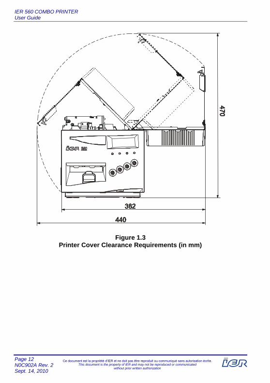
Figure 1.3 Printer Cover Clearance Requirements (in mm)

IER 560 COMBO PRINTER User Guide
Page 13 N0C902A Rev. 2
Sept. 14, 2010
Ce document est la propriété d’IER et ne doit pas être reproduit ou communiqué sans autorisation écrite. This document is the property of IER and may not be reproduced or communicated
without prior written authorization
Note: In the event of a problem (paper jam), or printer maintenance, ensure that there is enough space to rotate the cutter/burster module (see figure below).
Figure 1.4 Rotating the Cutter/Burster Module – Clearance Requirements (in mm)
IER 560 COMBO PRINTER User Guide
Page 14 N0C902A Rev. 2 Sept. 14, 2010
Ce document est la propriété d’IER et ne doit pas être reproduit ou communiqué sans autorisation écrite. This document is the property of IER and may not be reproduced or communicated
without prior written authorization
1.4. OPENING AND CLOSING THE PRINTER COVER
1.4.1. PRELIMINARY INFORMATION
!ATTENTION
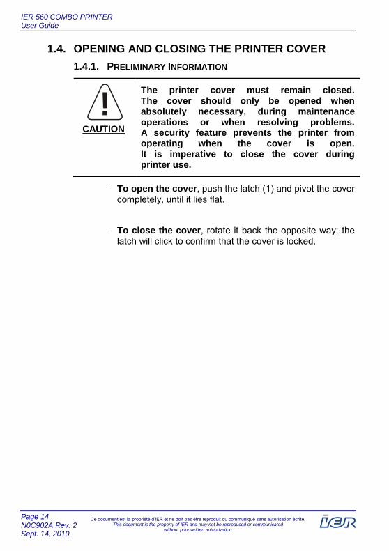
The printer cover must remain closed. The cover should only be opened when absolutely necessary, during maintenance operations or when resolving problems. A security feature prevents the printer from operating when the cover is open. It is imperative to close the cover during printer use.
To open the cover, push the latch (1) and pivot the cover completely, until it lies flat.
To close the cover, rotate it back the opposite way; the latch will click to confirm that the cover is locked.
CAUTION

IER 560 COMBO PRINTER User Guide
Page 15 N0C902A Rev. 2
Sept. 14, 2010
Ce document est la propriété d’IER et ne doit pas être reproduit ou communiqué sans autorisation écrite. This document is the property of IER and may not be reproduced or communicated
without prior written authorization
1
1 – Cover Latch
Figure 1.5 Opening the Cover
IER 560 COMBO PRINTER User Guide
Page 16 N0C902A Rev. 2 Sept. 14, 2010
Ce document est la propriété d’IER et ne doit pas être reproduit ou communiqué sans autorisation écrite. This document is the property of IER and may not be reproduced or communicated
without prior written authorization
1.5. OPENING AND CLOSING THE CUTTER/BURSTER MODULE
1.5.1. PRELIMINARY INFORMATION
!ATTENTION
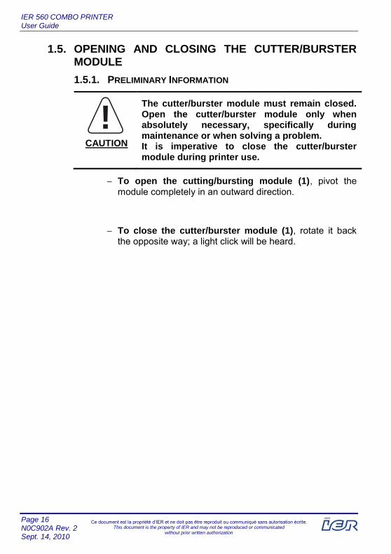
The cutter/burster module must remain closed. Open the cutter/burster module only when absolutely necessary, specifically during maintenance or when solving a problem. It is imperative to close the cutter/burster module during printer use.
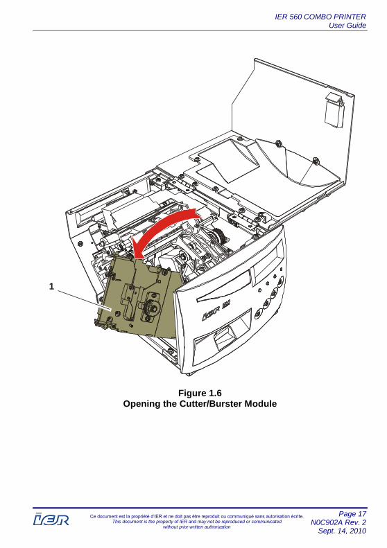
To open the cutting/bursting module (1), pivot the module completely in an outward direction.
To close the cutter/burster module (1), rotate it back the opposite way; a light click will be heard.
CAUTION
IER 560 COMBO PRINTER User Guide
Page 17 N0C902A Rev. 2
Sept. 14, 2010
Ce document est la propriété d’IER et ne doit pas être reproduit ou communiqué sans autorisation écrite. This document is the property of IER and may not be reproduced or communicated
without prior written authorization
1
Figure 1.6 Opening the Cutter/Burster Module

IER 560 COMBO PRINTER User Guide
Page 18 N0C902A Rev. 2 Sept. 14, 2010
Ce document est la propriété d’IER et ne doit pas être reproduit ou communiqué sans autorisation écrite. This document is the property of IER and may not be reproduced or communicated
without prior written authorization
1.6. PRINTER DESCRIPTION
1.6.1. EXTERIOR FRONT VIEW
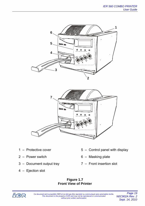
The IER 560 COMBO Printer includes:
A front panel equipped with:
▪ Document ejection slot (4),
▪ Retractable document output tray (3)
▪ Control panel with display (5).
▪ Masking plate to mask the front insertion slot (6)
▪ Front insertion slot
Power switch (2).
Protective cover (1).
IER 560 COMBO PRINTER User Guide
Page 19 N0C902A Rev. 2
Sept. 14, 2010
Ce document est la propriété d’IER et ne doit pas être reproduit ou communiqué sans autorisation écrite. This document is the property of IER and may not be reproduced or communicated
without prior written authorization
ON OFF
ALARM CHECK DISPLAY RECEPTION
RESET
EJECT
MENUTEST
ON LINE
EXIT
ENTER
+-
7
ON OFF
ALARM CHECK DISPLAY RECEPTION
RESET
EJECT
MENUTEST
ON LINE
EXIT
ENTER
+-
1
3
2
6
5
4
1 – Protective cover 5 – Control panel with display
2 – Power switch 6 – Masking plate
3 – Document output tray 7 – Front insertion slot
4 – Ejection slot
Figure 1.7 Front View of Printer
IER 560 COMBO PRINTER User Guide
Page 20 N0C902A Rev. 2 Sept. 14, 2010
Ce document est la propriété d’IER et ne doit pas être reproduit ou communiqué sans autorisation écrite. This document is the property of IER and may not be reproduced or communicated
without prior written authorization
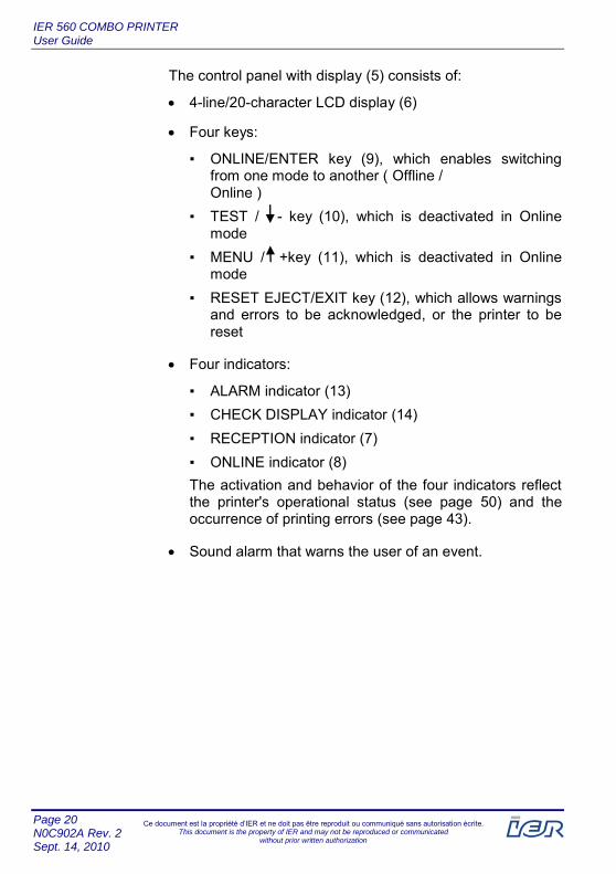
The control panel with display (5) consists of:
4-line/20-character LCD display (6)
Four keys:
▪ ONLINE/ENTER key (9), which enables switching from one mode to another ( Offline / Online )
▪ TEST / - key (10), which is deactivated in Online mode
▪ MENU / +key (11), which is deactivated in Online mode
▪ RESET EJECT/EXIT key (12), which allows warnings and errors to be acknowledged, or the printer to be reset
Four indicators:
▪ ALARM indicator (13)
▪ CHECK DISPLAY indicator (14)
▪ RECEPTION indicator (7)
▪ ONLINE indicator (8)
The activation and behavior of the four indicators reflect the printer's operational status (see page 50) and the occurrence of printing errors (see page 43).
Sound alarm that warns the user of an event.

IER 560 COMBO PRINTER User Guide
Page 21 N0C902A Rev. 2
Sept. 14, 2010
Ce document est la propriété d’IER et ne doit pas être reproduit ou communiqué sans autorisation écrite. This document is the property of IER and may not be reproduced or communicated
without prior written authorization
12
11 10
9
14
13
5
7
8
6
5 – Control panel with display
6 – Display
7 – RECEPTION indicator
8 – ONLINE indicator
9 – Mode key
10 – TEST key
11 – MENU key
12 – RESET key
13 – ALARM indicator
14 – CHECK DISPLAY indicator
Figure 1.8 Control Panel

IER 560 COMBO PRINTER User Guide
Page 22 N0C902A Rev. 2 Sept. 14, 2010
Ce document est la propriété d’IER et ne doit pas être reproduit ou communiqué sans autorisation écrite. This document is the property of IER and may not be reproduced or communicated
without prior written authorization
1.6.2. EXTERIOR REAR VIEW
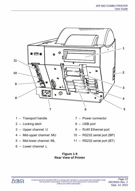
The rear of the IER 560 COMBO Printer includes:
Connector panel including:
▪ RS232 serial port (10), (BT: bag tag label printing applications)
▪ RS232 serial port (11), (BP: boarding pass printing applications)
▪ USB host port (8), (host system)
▪ RJ45 Ethernet port (9)
Transport handle (1).
Cover locking latch (2).
Paper channel selector with a basic configuration that offers:
▪ Upper channel: U (3), (BT: Loading of bag tag media)
▪ Mid-upper channel: MU (4), (BT: Loading of bag tag media)
▪ Mid-lower channel: ML (5), (BP: Loading of boarding pass media)
▪ Lower channel: L (6), (BP: Loading of boarding pass media)
Power connector (7).
IER 560 COMBO PRINTER User Guide
Page 23 N0C902A Rev. 2
Sept. 14, 2010
Ce document est la propriété d’IER et ne doit pas être reproduit ou communiqué sans autorisation écrite. This document is the property of IER and may not be reproduced or communicated
without prior written authorization
4
5
3
6
11
10
9
8
7
1
2
1 – Transport handle
2 – Locking latch
3 – Upper channel: U
4 – Mid-upper channel: MU
5 – Mid-lower channel: ML
6 – Lower channel: L
7 – Power connector
8 – USB port
9 – RJ45 Ethernet port
10 – RS232 serial port (BP)
11 – RS232 serial port (BT)
Figure 1.9 Rear View of Printer

IER 560 COMBO PRINTER User Guide
Page 24 N0C902A Rev. 2 Sept. 14, 2010
Ce document est la propriété d’IER et ne doit pas être reproduit ou communiqué sans autorisation écrite. This document is the property of IER and may not be reproduced or communicated
without prior written authorization
1.6.3. INTERIOR VIEW OF THE PRINTER
Opening the cover provides access to the following components:
Paper path, which is mainly comprised of:
▪ Ejector/document holder module (1)
▪ Separator (cutter/burster) module (2)
▪ Printing module (6) with printhead (7)
▪ Channel selector (5), (four channels), with a media sensor for each channel (4)
Power supply unit (3)

IER 560 COMBO PRINTER User Guide
Page 25 N0C902A Rev. 2
Sept. 14, 2010
Ce document est la propriété d’IER et ne doit pas être reproduit ou communiqué sans autorisation écrite. This document is the property of IER and may not be reproduced or communicated
without prior written authorization
46
1
5
2
3
4
7
Figure 1.10 Interior View of the Printer

IER 560 COMBO PRINTER User Guide
Page 26 N0C902A Rev. 2 Sept. 14, 2010
Ce document est la propriété d’IER et ne doit pas être reproduit ou communiqué sans autorisation écrite. This document is the property of IER and may not be reproduced or communicated
without prior written authorization
2 CONNECTING THE PRINTER AND POWER-UP
2.1. CONNECTING THE PRINTER
!DANGER
▪ This appliance must be grounded.
▪ This product must exclusively be connected to an electrical circuit that:
- includes a Ground Fault Circuit Interrupter (GFCI) and is compliant with IEC 364 and NFC15-100 regulations, and
- conforms to the voltage characteristics specified by the NF EN 50160 standard.
2.1.1. PROCEDURE FOR CONNECTING THE PRINTER
To connect the printer, simply proceed as follows:
Connect it to the power source
Connect it to the data communications system (PC, network)
WARNING
IER 560 COMBO PRINTER User Guide
Page 27 N0C902A Rev. 2
Sept. 14, 2010
Ce document est la propriété d’IER et ne doit pas être reproduit ou communiqué sans autorisation écrite. This document is the property of IER and may not be reproduced or communicated
without prior written authorization
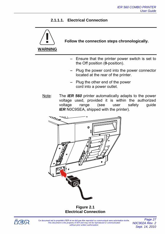
2.1.1.1. Electrical Connection
Follow the connection steps chronologically.
Ensure that the printer power switch is set to the Off position (0-position).
Plug the power cord into the power connector located at the rear of the printer.
Plug the other end of the power cord into a power outlet.
Note: The IER 560 printer automatically adapts to the power voltage used, provided it is within the authorized voltage range (see user safety guide IER N0C9SEA, shipped with the printer).
Figure 2.1 Electrical Connection
!DANGER
WARNING

IER 560 COMBO PRINTER User Guide
Page 28 N0C902A Rev. 2 Sept. 14, 2010
Ce document est la propriété d’IER et ne doit pas être reproduit ou communiqué sans autorisation écrite. This document is the property of IER and may not be reproduced or communicated
without prior written authorization
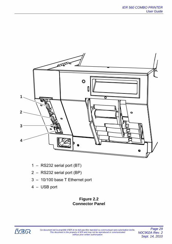
2.1.1.2. Data Connection
!ATTENTION
▪ The use of a data cable provided with a shielded braid is required to comply with the Class B requirements of FCC Regulations.
▪ Use a shielded RS232 cable fitted with metal-plated connector hoods. The cable shield must be connected to the connector hoods. The length of the cable must not exceed 15 m (49.2 ft.).
▪ If a USB cable connection is used, its length must not exceed 5 m (16.4 ft.).
To connect the printer to the host system, use one of the connection interfaces located at the rear of the printer:
RS232 serial port (1) intended for bag tag (BT) printing applications
RS232 serial port (2) intended for boarding pass (BP) printing applications
USB port (3) enabling connection with the Host system
10/100 base T Ethernet port (4)
CAUTION
IER 560 COMBO PRINTER User Guide
Page 29 N0C902A Rev. 2
Sept. 14, 2010
Ce document est la propriété d’IER et ne doit pas être reproduit ou communiqué sans autorisation écrite. This document is the property of IER and may not be reproduced or communicated
without prior written authorization
1
2
3
4
1 – RS232 serial port (BT)
2 – RS232 serial port (BP)
3 – 10/100 base T Ethernet port
4 – USB port
Figure 2.2 Connector Panel

IER 560 COMBO PRINTER User Guide
Page 30 N0C902A Rev. 2 Sept. 14, 2010
Ce document est la propriété d’IER et ne doit pas être reproduit ou communiqué sans autorisation écrite. This document is the property of IER and may not be reproduced or communicated
without prior written authorization
2.2. POWERING UP THE PRINTER
2.2.1. POWERING UP THE PRINTER
At the front of the printer, set the power switch to the I-position.
When powering up, the printer begins initialization. The length of initialization may vary according to its operational status and the type of application:
If the media has not been loaded, the printer displays a message and produces a beeping sound indicating that the media needs to be loaded.
If the media is already loaded, the printer is ready (READY) for printing.
ALARM CHECK DISPLAY RECEPTION
RESET
EJECTMENU
TESTON LINE
ON OFF
EXIT
ENTER
+
-
/
Figure 2.3 Powering Up the Printer

IER 560 COMBO PRINTER User Guide
Page 31 N0C902A Rev. 2
Sept. 14, 2010
Ce document est la propriété d’IER et ne doit pas être reproduit ou communiqué sans autorisation écrite. This document is the property of IER and may not be reproduced or communicated
without prior written authorization
2.2.2. POWERING DOWN THE PRINTER
To power down the printer, set the power switch located at the front of the printer to the 0-position.
ALARM CHECK DISPLAY RECEPTION
RESET
EJECTMENU
TESTON LINE
ON OFF
EXIT
ENTER
+
-
/
Figure 2.4 Powering Down the Printer

IER 560 COMBO PRINTER User Guide
Page 32 N0C902A Rev. 2 Sept. 14, 2010
Ce document est la propriété d’IER et ne doit pas être reproduit ou communiqué sans autorisation écrite. This document is the property of IER and may not be reproduced or communicated
without prior written authorization
3 INSTALLING AND LOADING THE MEDIA
3.1. ATB MEDIA
Note: The installation and loading of blank fanfold or roll type ATB media is performed in the lower channel (L channel) and the mid-lower channel (ML channel) of the printer (see page 22).
IMPORTANT: Use of the motorized stacker does not allow processing of ATB wallets as they might cause document jams.
3.1.1. INSTALLATION OF BLANK MEDIA
3.1.1.1. Media Installation Procedure
Power up the printer. The ONLINE indicator located on the printer's front panel lights up (see page 30).
Install the box(es) of blank media by following the instructions below:
IMPORTANT: Install the box(es):
▪ parallel to the printer
▪ centered in relation to the insertion slot
▪ with the heat-sensitive side of the media facing up

IER 560 COMBO PRINTER User Guide
Page 33 N0C902A Rev. 2
Sept. 14, 2010
Ce document est la propriété d’IER et ne doit pas être reproduit ou communiqué sans autorisation écrite. This document is the property of IER and may not be reproduced or communicated
without prior written authorization
Note: When loading ATB stock, always begin with the lowest channel. Refer to the channel identification on the printer's rear panel to locate the channels (see figure below).
1
2
3
4
1 – Lower channel: L
2 – Mid-lower channel: ML
3 – Mid-upper channel: MU
4 – Upper channel: U
Figure 3.1 Channel Identification (Rear View of Printer)

IER 560 COMBO PRINTER User Guide
Page 34 N0C902A Rev. 2 Sept. 14, 2010
Ce document est la propriété d’IER et ne doit pas être reproduit ou communiqué sans autorisation écrite. This document is the property of IER and may not be reproduced or communicated
without prior written authorization
3.1.1.2. Examples of Installation of Blank ATB Media
1
2
1 – Stock 1 ATB media (L channel)
2 – Stock 2 ATB media (ML channel)
Figure 3.2 Example 1: Installation of Fanfold ATB Media

IER 560 COMBO PRINTER User Guide
Page 35 N0C902A Rev. 2
Sept. 14, 2010
Ce document est la propriété d’IER et ne doit pas être reproduit ou communiqué sans autorisation écrite. This document is the property of IER and may not be reproduced or communicated
without prior written authorization
3
4
3 – Stock 1 ATB media (L channel)
4 – Stock 2 ATB media (ML channel)
Figure 3.3 Example 2: Installation of Fanfold and Roll Type ATB Media

IER 560 COMBO PRINTER User Guide
Page 36 N0C902A Rev. 2 Sept. 14, 2010
Ce document est la propriété d’IER et ne doit pas être reproduit ou communiqué sans autorisation écrite. This document is the property of IER and may not be reproduced or communicated
without prior written authorization
3.1.2. LOADING OF BLANK ATB MEDIA INTO THE PRINTER
Load the leading document from stock 1 (1) into the lower channel (L channel).
1
1
1 – Leading document from stock 1
Figure 3.4 Loading of Stock 1 Media into the Lower Channel (L Channel)
Note: Upon its insertion into the channel, the coupon is pulled in and automatically positioned in the printer, according to the program parameters and the type of separation mark present on the media.

IER 560 COMBO PRINTER User Guide
Page 37 N0C902A Rev. 2
Sept. 14, 2010
Ce document est la propriété d’IER et ne doit pas être reproduit ou communiqué sans autorisation écrite. This document is the property of IER and may not be reproduced or communicated
without prior written authorization
Next, load the leading document from stock 2 (2) into the mid-lower channel (ML channel).
2
2
2 – Leading Document from Stock 2 ( Fanfold or Roll Media)
Figure 3.5 Loading of Stock 2 Media into the Mid-Lower Channel (ML CHANNEL)

IER 560 COMBO PRINTER User Guide
Page 38 N0C902A Rev. 2 Sept. 14, 2010
Ce document est la propriété d’IER et ne doit pas être reproduit ou communiqué sans autorisation écrite. This document is the property of IER and may not be reproduced or communicated
without prior written authorization
3.2. BAG TAG MEDIA
Note: The installation and loading of blank roll type bag tag media is performed in the mid-upper channel (MU channel) and the upper channel (U channel) of the printer (see page 22).
3.2.1. INSTALLATION OF BLANK MEDIA
3.2.1.1. Media Installation Procedure
Follow the instructions below to install and position the blank media roll(s):
IMPORTANT: Install the roll(s):
▪ parallel to the printer
▪ centered in relation to the insertion slot
▪ with the heat-sensitive side of the media facing up
IER 560 COMBO PRINTER User Guide
Page 39 N0C902A Rev. 2
Sept. 14, 2010
Ce document est la propriété d’IER et ne doit pas être reproduit ou communiqué sans autorisation écrite. This document is the property of IER and may not be reproduced or communicated
without prior written authorization
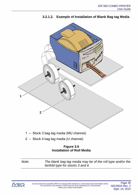
3.2.1.2. Example of Installation of Blank Bag tag Media
2
1
1 – Stock 3 bag tag media (MU channel)
2 – Stock 4 bag tag media (U channel)
Figure 3.6 Installation of Roll Media
Note: The blank bag tag media may be of the roll type and/or the fanfold type for stocks 3 and 4.

IER 560 COMBO PRINTER User Guide
Page 40 N0C902A Rev. 2 Sept. 14, 2010
Ce document est la propriété d’IER et ne doit pas être reproduit ou communiqué sans autorisation écrite. This document is the property of IER and may not be reproduced or communicated
without prior written authorization
3.2.2. LOADING OF BLANK BAG TAG MEDIA INTO THE PRINTER
Load the leading document of the stock 3 (1) roll or fanfold media into the mid-lower channel (ML channel).
3
1
1 – Leading document of stock 3 roll media
Figure 3.7 Loading of Stock 3 Media into the Mid-Upper Channel (MU Channel)
Note: Upon its insertion into the channel, the media is pulled in and automatically positioned in the printer, according to the program parameters and the type of separation mark present on the media.

IER 560 COMBO PRINTER User Guide
Page 41 N0C902A Rev. 2
Sept. 14, 2010
Ce document est la propriété d’IER et ne doit pas être reproduit ou communiqué sans autorisation écrite. This document is the property of IER and may not be reproduced or communicated
without prior written authorization
Load the leading document of the stock 4 (2) roll or fanfold media into the upper channel (U channel).
4
2
2 – Leading document from stock 4 media
Figure 3.8 Loading of Stock 4 Media into the Upper Channel (U Channel)

IER 560 COMBO PRINTER User Guide
Page 42 N0C902A Rev. 2 Sept. 14, 2010
Ce document est la propriété d’IER et ne doit pas être reproduit ou communiqué sans autorisation écrite. This document is the property of IER and may not be reproduced or communicated
without prior written authorization
3.3. MEDIA REMOVAL
3.3.1. PROCEDURE
To remove the media from the printer, grasp the media strip and simply pull it towards the rear of the printer.
IMPORTANT: To do this, you do not have to open the cover, nor perform any action inside the printer.
Figure 3.9 Media Removal
IER 560 COMBO PRINTER User Guide
Page 43 N0C902A Rev. 2
Sept. 14, 2010
Ce document est la propriété d’IER et ne doit pas être reproduit ou communiqué sans autorisation écrite. This document is the property of IER and may not be reproduced or communicated
without prior written authorization
4 PRINTER OPERATION
4.1. INDICATOR AND KEY FUNCTIONS
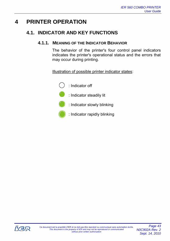
4.1.1. MEANING OF THE INDICATOR BEHAVIOR
The behavior of the printer's four control panel indicators indicates the printer's operational status and the errors that may occur during printing.
Illustration of possible printer indicator states:
: Indicator off
: Indicator steadily lit
: Indicator slowly blinking
: Indicator rapidly blinking

IER 560 COMBO PRINTER User Guide
Page 44 N0C902A Rev. 2 Sept. 14, 2010
Ce document est la propriété d’IER et ne doit pas être reproduit ou communiqué sans autorisation écrite. This document is the property of IER and may not be reproduced or communicated
without prior written authorization
Assigned Meaning of Indicator Behavior:
Indicator State Cause Remedy
Alarm Check Display
Reception Online
Printer powered down
-
Printer initialization following power-up
(Alarm + Reception indicators and Check Display + Online indicators blinking alternately)
-
Printer powered up, online (READY)
-
Printer powered up, transaction in progress
-
Note: In addition to the indicator light signals, the sound alarm is activated whenever an error or warning situation occurs on the printer. There are two types of sound signals:
A short (5 seconds) beeping sound signal indicates that a minor error has occurred (e.g. printer out of paper).
A continuous beeping sound signal warns the user of a technical error (e.g. paper jam).
IER 560 COMBO PRINTER User Guide
Page 45 N0C902A Rev. 2
Sept. 14, 2010
Ce document est la propriété d’IER et ne doit pas être reproduit ou communiqué sans autorisation écrite. This document is the property of IER and may not be reproduced or communicated
without prior written authorization
4.1.2. CONTROL PANEL KEY FUNCTIONS
▪ When in Online mode, only the following two keys are active and can be used to respond to the indicator signals:
Allows switching from online to offline mode (and vice versa).
Allows the user to acknowledge an error or warning situation, indicated by a sound alarm (pressing the key stops the alarm). In the event of a technical error, pressing the key causes the built-in automatic error compensation feature to be activated.
▪ When in Offline mode, only the TEST key can be used to:
Initiate a test document selection.
ONLINE Key
RESET/ EJECT Key
TEST Key

IER 560 COMBO PRINTER User Guide
Page 46 N0C902A Rev. 2 Sept. 14, 2010
Ce document est la propriété d’IER et ne doit pas être reproduit ou communiqué sans autorisation écrite. This document is the property of IER and may not be reproduced or communicated
without prior written authorization
4.2. DOCUMENT PRINTING
Preliminary Steps: Before using the printer, perform the following checks:
Printer connected to the power source and the host system, see page 26.
Printer powered up, see page 30.
Consumables loaded into the printer, see page 32.
If necessary, refer to the paragraph describing printer functions, see page 43.
4.2.1. PROCEDURE FOR PRINTING DOCUMENTS
Set the printer to Online mode by pressing the ONLINE key; the Online indicator will be steadily lit and a message will appear on the display:
560 READY R e v i s i o n 8 x x x x – 1 . x x
S / N: X X X X X X X
Send a print command from the host system to the printer. The Reception indicator blinks slowly until the document is printed; then, only the Online indicator remains lit.
At the end of printing, the document is automatically separated (cutting or bursting method - depending on the size and type of media used) and is then presented to the user.
Note: Only previously cut long documents (bag tags) are held back in the output slot until they are removed. To retrieve such a document from the holder, simply pull it towards you.
IER 560 COMBO PRINTER User Guide
Page 47 N0C902A Rev. 2
Sept. 14, 2010
Ce document est la propriété d’IER et ne doit pas être reproduit ou communiqué sans autorisation écrite. This document is the property of IER and may not be reproduced or communicated
without prior written authorization
3
1
2
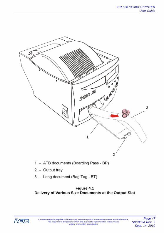
1 – ATB documents (Boarding Pass - BP)
2 – Output tray
3 – Long document (Bag Tag - BT)
Figure 4.1 Delivery of Various Size Documents at the Output Slot

IER 560 COMBO PRINTER User Guide
Page 48 N0C902A Rev. 2 Sept. 14, 2010
Ce document est la propriété d’IER et ne doit pas être reproduit ou communiqué sans autorisation écrite. This document is the property of IER and may not be reproduced or communicated
without prior written authorization
5 USER LEVEL TROUBLESHOOTING
5.1. OPERATING FAULTS
An operating fault occurring in the printer generates, in most cases, the activation of indicators and of a sound signal.
NOTE: A beeping sound alarm lasting 5 seconds indicates a minor error, whereas a continuous beeping sound (or one that lasts 10 seconds) indicates a technical error.
5.1.1. WHEN POWERING UP, THE PRINTER DOES NOT START UP
Note: If necessary, to facilitate access to the rear of the printer, unload the paper, see page 42.
Power down the printer (set the power switch to the 0-position).
Check the presence of power at the power source with another electrical appliance.
Check the connection of the power cable to the printer connector and to the power source.
Restart the printer (set the power switch to the I-position).
Wait for the printer to initialize and then ensure that the Online indicator is steadily lit.
If, after all these steps, the printer still fails to start up, call the help desk.
IER 560 COMBO PRINTER User Guide
Page 49 N0C902A Rev. 2
Sept. 14, 2010
Ce document est la propriété d’IER et ne doit pas être reproduit ou communiqué sans autorisation écrite. This document is the property of IER and may not be reproduced or communicated
without prior written authorization
5.1.2. THE PRINTER DOES NOT RECEIVE PRINT DATA
Note: If necessary, to facilitate access to the rear of the printer, unload the paper, see page 42.
Power down the printer (set the power switch to the 0-position).
Check the connection of the data cable to the printer connector and to the IT system (computer, network, hub, etc.).
Restart the printer (set the power switch to the I-position) and check that the Online indicator is steadily lit.
Note: If necessary, reload the printer with paper, see page 32.
Send a print command from the host system; the printer should execute the requested printing.
If all these steps are not effective, call the help desk.
5.1.3. THE PAPER IS NOT FEEDING
Try to target the problem by reading the message on the printer's control panel display.
Unload the paper and then reload it; this will allow the paper path to reinitialize.
Ensure that no paper chaff remains in the paper path and is preventing the feeding of documents.
If, after all these steps, the problem persists, call the help desk.

IER 560 COMBO PRINTER User Guide
Page 50 N0C902A Rev. 2 Sept. 14, 2010
Ce document est la propriété d’IER et ne doit pas être reproduit ou communiqué sans autorisation écrite. This document is the property of IER and may not be reproduced or communicated
without prior written authorization
5.1.4. POOR PRINT QUALITY
Several reasons may cause poor print quality:
▪ Dirty print mechanism
▪ Print parameter settings do not correspond to the type of media used
▪ Faulty part(s)
Regardless of what it is, this type of operating malfunction requires help desk assistance.
5.1.5. FREQUENT ERROR SIGNALS
IMPORTANT: Once an error is resolved, press the RESET/EJECT key in order to reinitialize the printer and to acknowledge the error.
Review of the possible printer indicator states:
: Indicator off
: Indicator steadily lit
: Indicator slowly blinking
: Indicator rapidly blinking

IER 560 COMBO PRINTER User Guide
Page 51 N0C902A Rev. 2
Sept. 14, 2010
Ce document est la propriété d’IER et ne doit pas être reproduit ou communiqué sans autorisation écrite. This document is the property of IER and may not be reproduced or communicated
without prior written authorization
Overview of Indicator Behavior and Printer Messages:
Message and Indicator States
Cause Remedy
Alarm Check Display
Reception Online
One of the four stocks is empty
- Load paper in the printer (see page 32).
- Press the RESET/EJECT key
Paper detection error
- Unload, then reload the paper (see page 42 and page 32).
- Press the RESET/EJECT key
Requested stock is empty
- Load paper (see page 32).
Paper stock empty (thus printing rejected or interrupted)
- Load paper (see page 32).
560 READY BP1 BP 2 BP3 BT
empty
S/N: XXXXXXX
BAD PAPER DETECTION Please reload
paper bin S/N: XXXXXXX
OUT OF REQUESTED PAPER
Please load media
WARNING OUT OF PAPER
ERR5Oxx

IER 560 COMBO PRINTER User Guide
Page 52 N0C902A Rev. 2 Sept. 14, 2010
Ce document est la propriété d’IER et ne doit pas être reproduit ou communiqué sans autorisation écrite. This document is the property of IER and may not be reproduced or communicated
without prior written authorization
Message and Indicator States
Cause Remedy
Alarm Check Display
Reception Online
Paper jam
- Clear the paper jam in the printer.
- Press the RESET/EJECT key
Cutter/burster module open
- Close the cutter/burster module (see page 16).
- Press the RESET/EJECT key
Cover open
- Close the cover (see page 14).
- Press the - RESET/EJECT key
Data transmission error (no connection with the host system)
- Check the connection of the data cable (see page 28).
- Resend the computer command.
- Press the RESET/EJECT key
COUPON JAM [X] Please correct and
then press “RESET” S/N: XXXXXXX
CUTTER OPEN Please close cutter module
S/N: XXXXXXX
COVER OPEN Please close cover
S/N: XXXXXXX
560 READY Link down
S/N: XXXXXXX

IER 560 COMBO PRINTER User Guide
Page 53 N0C902A Rev. 2
Sept. 14, 2010
Ce document est la propriété d’IER et ne doit pas être reproduit ou communiqué sans autorisation écrite. This document is the property of IER and may not be reproduced or communicated
without prior written authorization
5.2. CLEARING A DOCUMENT JAM
Preliminary Steps: In order to effectively clear a jam, refer to the following sections:
Indicator and Key Functions, see page 43.
Frequent Error Signals, see page 50.
5.2.1. PROCEDURE FOR CLEARING A DOCUMENT JAM
Unload the paper from the printer
Open the printer cover in order to locate the jam, see page 14.
Clear the jam in the area(s) concerned.
Close the printer cover, see page 14.
Reload the printer with paper and press the RESET/EJECT key in order to reinitialize the printer and acknowledge the error, see page 32.
Note: If necessary, rotate the cutter/burster module in order to facilitate access to the paper path; the cutter/burster module being open, the entire paper path is accessible (see page 16).
IER 560 COMBO PRINTER User Guide
Page 54 N0C902A Rev. 2 Sept. 14, 2010
Ce document est la propriété d’IER et ne doit pas être reproduit ou communiqué sans autorisation écrite. This document is the property of IER and may not be reproduced or communicated
without prior written authorization
6 PRINTER MAINTENANCE
6.1. PERIODIC MAINTENANCE RECOMMENDATIONS
Schedule: Every 2 weeks or after 2,000 m (6,562 ft.) of printing.
Total Estimated Time: 15 min.
Necessary Tools/Products: IER cleaning kit, P/N S32129A
!DANGER
Before starting to clean the printer:
- unload the paper from the printer,
- power down the printer,
- disconnect the printer from the power source,
- disconnect the data cable.
6.1.1. MAINTENANCE SCHEDULE
For optimum printer performance, under normal operating conditions, IER recommends periodic maintenance be carried out every 2 weeks or after printing of 2,000 m (6,562 ft.) of media.
IMPORTANT: The frequency of periodic maintenance must be adapted to the particular printer environment and operating conditions (dusty surroundings, media quality, throughput, etc.).
IER recommends that you use the IER cleaning kit, P/N S32129A, follow the instructions in the kit, and apply the procedures described in this document.
!ATTENTION
IER disclaims all liability for incidents arising from failure to follow its recommendations regarding service intervals, products and procedures.
CAUTION
WARNING

IER 560 COMBO PRINTER User Guide
Page 55 N0C902A Rev. 2
Sept. 14, 2010
Ce document est la propriété d’IER et ne doit pas être reproduit ou communiqué sans autorisation écrite. This document is the property of IER and may not be reproduced or communicated
without prior written authorization
6.2. PROCEDURES PRIOR TO PERIODIC MAINTENANCE
6.2.1. GENERAL DUSTING
!DANGER
To perform this, IER recommends that only the air can provided in the kit be used since its gas has been tested and approved as non-flammable and non-explosive. IER disclaims all liability for incidents arising from the use of another product. DO NOT USE THE AIR CAN WHEN THERE IS ONLY LITTLE AIR LEFT; THE CAN CONTAINS MOSTLY PROPELLANT, WHICH IS HIGHLY FLAMMABLE.
Follow the safety precautions on the can as well as those indicated above when using the air can supplied in the cleaning kit to remove paper chaff and to perform a general dusting of the printer by directing the air flow (see Figure 6.1 and Figure 6.2):
▪ Arrow #1 inside the media insertion channels, toward the media sensors
▪ Arrow #2 toward the different sensors located on the cutter/burster module: the oscillating synchronization sensor, the blade position sensor and the paper output sensor
▪ Arrow #3 to the cutter blade and counter blade, as well as to the internal parts of the cutter/burster module
▪ Arrow #4 under the paper guide and the print mechanism
▪ Arrow #5 above and under the platen
▪ Arrow #6 inside the ejection/document holder module
▪ Arrow #7 into the paper output slot of the front panel
WARNING

IER 560 COMBO PRINTER User Guide
Page 56 N0C902A Rev. 2 Sept. 14, 2010
Ce document est la propriété d’IER et ne doit pas être reproduit ou communiqué sans autorisation écrite. This document is the property of IER and may not be reproduced or communicated
without prior written authorization
Figure 6.1 General Dusting of the Printer

IER 560 COMBO PRINTER User Guide
Page 57 N0C902A Rev. 2
Sept. 14, 2010
Ce document est la propriété d’IER et ne doit pas être reproduit ou communiqué sans autorisation écrite. This document is the property of IER and may not be reproduced or communicated
without prior written authorization
Figure 6.2 General Dusting of the Printer (continued)
IER 560 COMBO PRINTER User Guide
Page 58 N0C902A Rev. 2 Sept. 14, 2010
Ce document est la propriété d’IER et ne doit pas être reproduit ou communiqué sans autorisation écrite. This document is the property of IER and may not be reproduced or communicated
without prior written authorization
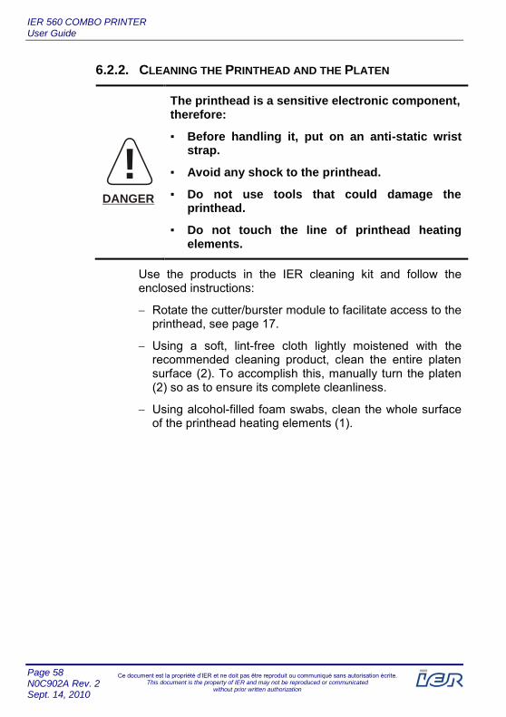
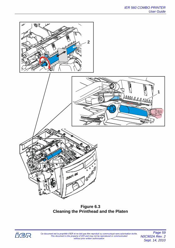
6.2.2. CLEANING THE PRINTHEAD AND THE PLATEN
!DANGER
The printhead is a sensitive electronic component, therefore:
▪ Before handling it, put on an anti-static wrist strap.
▪ Avoid any shock to the printhead.
▪ Do not use tools that could damage the printhead.
▪ Do not touch the line of printhead heating elements.
Use the products in the IER cleaning kit and follow the enclosed instructions:
Rotate the cutter/burster module to facilitate access to the printhead, see page 17.
Using a soft, lint-free cloth lightly moistened with the recommended cleaning product, clean the entire platen surface (2). To accomplish this, manually turn the platen (2) so as to ensure its complete cleanliness.
Using alcohol-filled foam swabs, clean the whole surface of the printhead heating elements (1).
IER 560 COMBO PRINTER User Guide
Page 59 N0C902A Rev. 2
Sept. 14, 2010
Ce document est la propriété d’IER et ne doit pas être reproduit ou communiqué sans autorisation écrite. This document is the property of IER and may not be reproduced or communicated
without prior written authorization
2
1
Figure 6.3 Cleaning the Printhead and the Platen

IER 560 COMBO PRINTER User Guide
Page 60 N0C902A Rev. 2 Sept. 14, 2010
Ce document est la propriété d’IER et ne doit pas être reproduit ou communiqué sans autorisation écrite. This document is the property of IER and may not be reproduced or communicated
without prior written authorization
6.3. RETURNING THE PRINTER TO OPERATING CONDITION AFTER PERIODIC MAINTENANCE
6.3.1. PROCEDURE TO FOLLOW PRIOR TO OPERATING THE
PRINTER
After performing the periodic maintenance operations:
Allow the printer cleaning product to dry.
Rotate the cutter/burster module into its original position, see page 16.
Close the printer cover, see page 14.
Connect the data cable and power cable, see page 26.
Power up the printer, see page 30.
Load the printer with paper, see page 32.
Print a document and check the print quality, see page 46.


![IER Präsentation e 10-2016 [Kompatibilitätsmodus] · IER Presentation Content 1. Institute of Energy Economics and the Rational Use of Energy (IER) 2. Global Analysis i. NEWAGE](https://static.documents.pub/doc/80x56/5f8ac43120119957e4042e8c/ier-prsentation-e-10-2016-kompatibilittsmodus-ier-presentation-content-1.jpg)


