70
IES Fast Speed Gauges IES Fast Speed Gauges IES Fast Speed Gauges IES Fast Speed Gauges SCOTT A. AGER [email protected] 2/11/2016 Copyright (c) 2015 IES Global, Inc. All rights reserved.

IES Fast Speed GaugesIES Fast Speed GaugesIES Fast Speed GaugesIES Fast Speed Gauges
S C O T T A . A G E R
S C O T T @ I E S G L O B A L I N C . C O M
2/11/2016 Copyright (c) 2015 IES Global, Inc. All rights reserved.
IES, Inc.IES, Inc.IES, Inc.IES, Inc.

Company LocationCompany LocationCompany LocationCompany Location
Navarre, Florida

Contact InformationContact InformationContact InformationContact Information
Contact Scott Ager for questions regarding gauge maintenance, programming, applications, and gauge data.
Instrumentation and Engineering Services, Inc.7552 Navarre Pkwy, Suite 42
Navarre, Florida 32566
Office: +1 850 515-1244Cell: +1 850 206-1022
E-MAIL: [email protected] Site: www.IESrecorders.com
www.IESglobalinc.com

Analyzing Gauge Data Analyzing Gauge Data Analyzing Gauge Data Analyzing Gauge Data
For more extensive gauge data analysis, you can contact Bob Haney* for more information at his email address:
*Robert “Bob” Haney is an independent
consultant located in Calgary, Canada and is
not an employee of IES, Inc.

Background of Scott AgerBackground of Scott AgerBackground of Scott AgerBackground of Scott Ager
�Co-Founder of IES in 1987
�IES designed and developed miniature, high shock instrumentation
�Designed and developed the original FAST, high speed pressure gauge for measuring the dynamic pressure when a propellant or perforating gun fired.
�Designed the Shock Mitigater
�Designed the Gauge Body and Drop Bar attachments.
�Developed the Gauge Software.
Gauge DefinitionsGauge DefinitionsGauge DefinitionsGauge Definitions

Gauge DefinitionsGauge DefinitionsGauge DefinitionsGauge Definitions
Gauge (High Speed or “Fast” Gauge)
◦ The Gauge is defined as the entire pressure tool, including the individual gauge sections, shock mitigator, OWR, pressure and RTDtemperature sensors (w/ optional accelerometers), battery fixture, and battery pack.
Gauge DefinitionsGauge DefinitionsGauge DefinitionsGauge Definitions
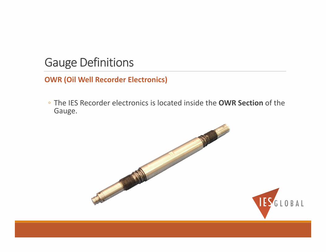
OWR (Oil Well Recorder Electronics)
◦ The IES Recorder electronics is located inside the OWR Section of the Gauge.
Gauge DefinitionsGauge DefinitionsGauge DefinitionsGauge Definitions
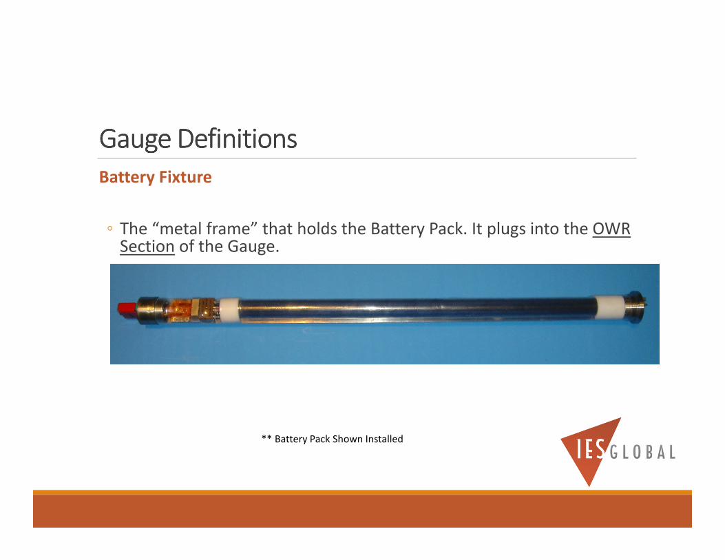
Battery Fixture
◦ The “metal frame” that holds the Battery Pack. It plugs into the OWR Section of the Gauge.
** Battery Pack Shown Installed

Gauge DefinitionsGauge DefinitionsGauge DefinitionsGauge Definitions
Battery Pack
◦ The potted battery is used to power the Gauge. It is located inside the Battery Fixture.

Gauge DefinitionsGauge DefinitionsGauge DefinitionsGauge Definitions
Interface Box
◦ The interface between the computer and the gauge. It is required to program the gauge and download the data.

Gauge DefinitionsGauge DefinitionsGauge DefinitionsGauge Definitions
Shock Mitigater
◦ Used to reduce the high shock and vibration inside the Gauge when the guns are fired. It is installed between the Gauge and the Tool/Guns.
Gauge SpecificationsGauge SpecificationsGauge SpecificationsGauge Specifications

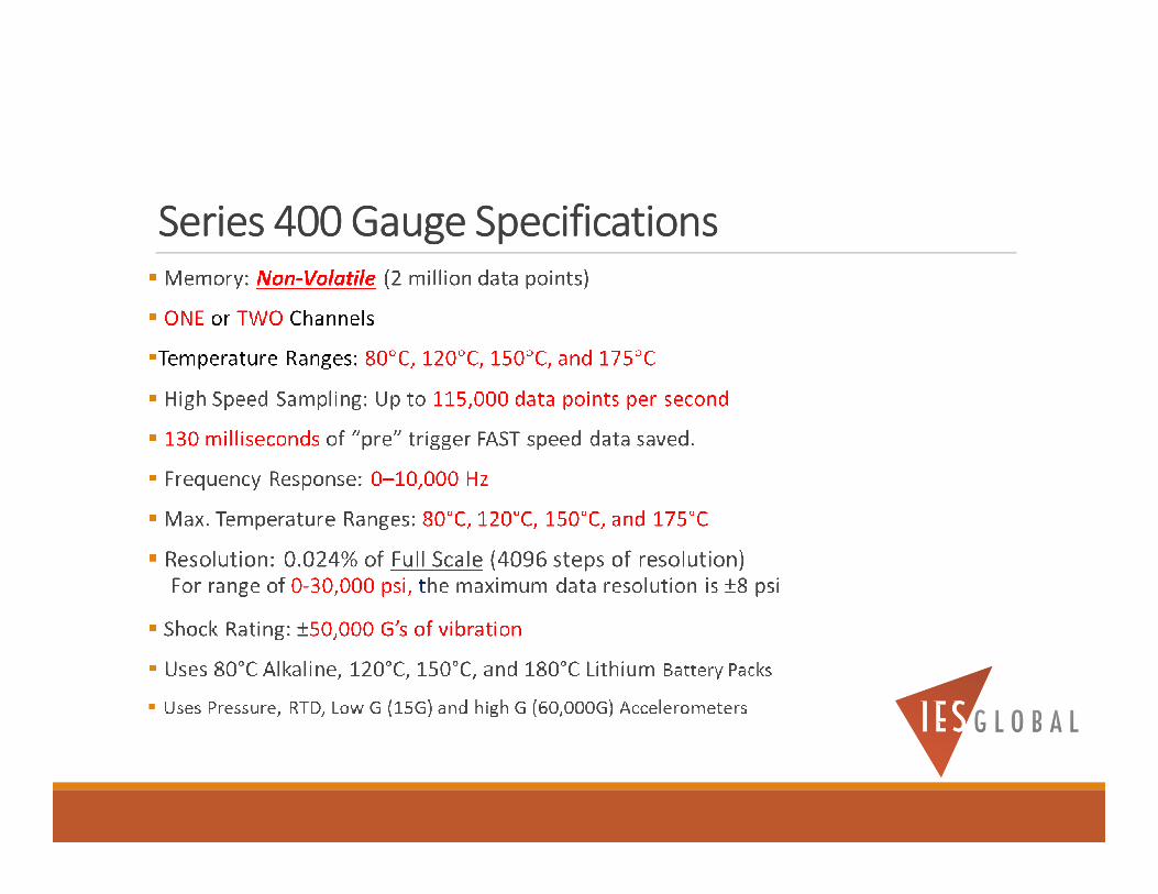
Series 400 Gauge SpecificationsSeries 400 Gauge SpecificationsSeries 400 Gauge SpecificationsSeries 400 Gauge Specifications
Size and Weight
◦ 1-11/16” OD Gauge
◦ 50” length, 25 lbs.
◦ With Shock Mitigater, 67” length, 34 lbs.
◦ Additional Battery Section: 17.5”, 8 lbs.

Gauge Gauge Gauge Gauge Lease Lease Lease Lease and Purchase Optionsand Purchase Optionsand Purchase Optionsand Purchase Options
• 80°C and 120°C Gauges are available for Lease or Purchase
• 150°C and 175°C Gauges can ONLY be Leased
• Contact Scott Ager for more information on leasing
Series 400 Gauge SpecificationsSeries 400 Gauge SpecificationsSeries 400 Gauge SpecificationsSeries 400 Gauge Specifications

Series 400 Sensor OptionsSeries 400 Sensor OptionsSeries 400 Sensor OptionsSeries 400 Sensor Options
Sensors: - High Pressure (0-30,000 psi, 0-10,000 Hz response)
- RTD (temperature)
- Low G Accelerometer: used to measure tool movement (±15 G’s)
- High G Accelerometer: used to measure tool vibrations (±60,000 G’s)

400 Gauge Options400 Gauge Options400 Gauge Options400 Gauge Options
1- 11/16” OD Gauges1, 150°C and 175°C (For Lease ONLY)
� #IES-GAUGE-411
� 30,000 psi Pressure sensor, and Temperature RTD
� #IES-GAUGE-412
� 30,000 psi Pressure sensor, Temperature RTD, and
±15G Accelerometer
� #IES-GAUGE-4132
� 30,000 psi Pressure sensor, Temperature RTD, and ±60,000 G, and ±15G Accelerometers
1 1-11/16” OD Shock Mitigater (#IES-SM-11116) and Battery Fixture included.2222NOT AVAILABLE UNTIL NOT AVAILABLE UNTIL NOT AVAILABLE UNTIL NOT AVAILABLE UNTIL 2016201620162016

Series 400 Gauge for Lease ONLYSeries 400 Gauge for Lease ONLYSeries 400 Gauge for Lease ONLYSeries 400 Gauge for Lease ONLY
• 80°C and 120°C Gauges can be Leased or purchased
• 150°C and 175°C Gauges can ONLY be Leased
• Contact Scott Ager for more information on leasing

Placement of the GaugePlacement of the GaugePlacement of the GaugePlacement of the Gauge

Placement of the GaugePlacement of the GaugePlacement of the GaugePlacement of the Gauge
-Wireline
- Gauge is normally located below the gun.
-TCP
- Gauge can be located below the gun
- Gauge can be located above the gun
- Gauge Carrier is STRONGLY RECOMMENDED
-Drop Bar
- Gauge can be used as a “DROP BAR” to fire a gun, AND collect FAST Speed pressure / temperature data at the same time

Gauge CarrierGauge CarrierGauge CarrierGauge Carrier

Gauge CarrierGauge CarrierGauge CarrierGauge Carrier
Use separate Gauge Carriers for each gauge.
I suggest modifying an old perforating gun casing for use as a Gauge Carrier.
Make sure the Gauge Carrier is long enough to contain the entire Gauge Assembly, which consists of the Shock Mitigater, the Gauge, and two Battery Sections for running two battery Packs per gauge.

Gauge CarrierGauge CarrierGauge CarrierGauge CarrierALWAYS use the Shock Mitigater inside the Gauge Carrier (unless you are using a High G Accelerometer).
Use “reverse threads” for the Gauge Carrier internal SUB.
SHOCK MITIGATER

Gauge CarrierGauge CarrierGauge CarrierGauge CarrierMake sure there are a sufficient number of holes drilled in the Gauge Carrier to allow pressure to reach the Gauge’s Pressure Ports unobstructed.

Gauge CarrierGauge CarrierGauge CarrierGauge CarrierTry to allow at least 1 inch clearance between the Gauge body and the inside of the Gauge Carrier, if possible.
Use some type of
centralizer. I recommend
using a VITON DISK as a
spacer…

Gauge CarrierGauge CarrierGauge CarrierGauge Carrier
The Gauge body must be “free floating” and MUST NOT come in contact with the inside wall of the Gauge Carrier. Metal on Metal contact between the Gauge and the Carrier could cause excessive vibrations and possibly damage the gauge.
The BULL NOSE Section of the Gauge should not come into direct contact with the bottom or sides of the Gauge Carrier. A VITON DISK spacer can be used at the BULL NOSE end of the Gauge as a “CENTRALIZER”.
ALWAYS FLUSH OUT ANY DEBRIS THAT COLLECTED INSIDE THE GAUGE CARRIER AFTER A JOB, BEFORE YOU REMOVE THE GAUGE.

Gauge CarrierGauge CarrierGauge CarrierGauge CarrierImportant! Use “reverse threads” for the Gauge Carrier threads which connect the outer carrier casing, with the Carrier SUB assembly.
◦ When the Gauge Carrier’s outer casing is unscrewed and removed from around the Gauge, it should unscrew in the OPPOSITE direction from how the Gauge Sections are screwed together.
◦ Reverse threads prevents the Gauge sections from accidentally unscrewing when you are unscrewing and removing the Gauge Carrier outer casing. If a Gauge Section is loosened while the Gauge Carrier is being disassembled, it could disconnect the Gauge’s Battery Pack.

Gauge CarrierGauge CarrierGauge CarrierGauge CarrierImportant! Use “reverse threads” for the Gauge Carrier.
Use “REVERSE” ThreadsUse “REVERSE” ThreadsUse “REVERSE” ThreadsUse “REVERSE” Threads

“Drop Bar” Gauge“Drop Bar” Gauge“Drop Bar” Gauge“Drop Bar” Gauge
The 1-11/16”OD Gauge can be configured and used as a DROP BAR.
The Gauge DROP BAR can be used to fire the guns and record the Gun’s high speed pressure profile at the same time. It can be left in position to record the SLOW speed pressure data afterwards. Then the Gauge can be fished out of the well and the Data retrieved.
This data can also be use to determine if the Guns fired properly.
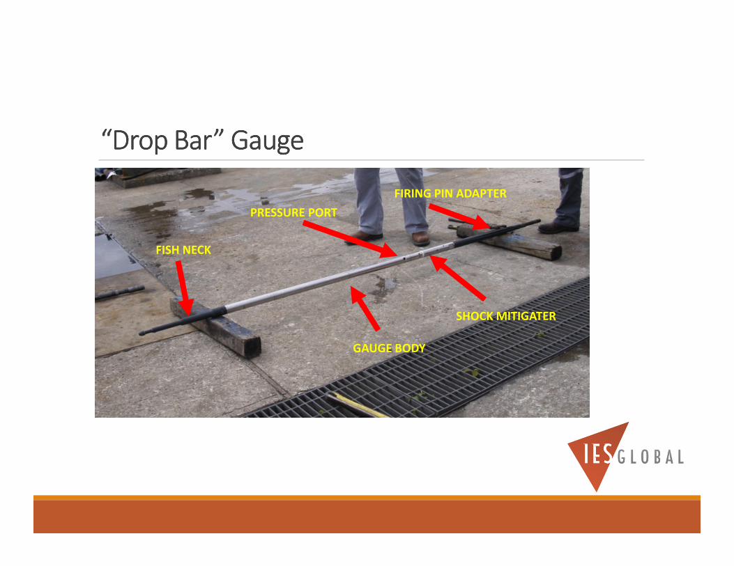
“Drop Bar” Gauge“Drop Bar” Gauge“Drop Bar” Gauge“Drop Bar” Gauge
GAUGE BODY
SHOCK MITIGATER
FISH NECK
FIRING PIN ADAPTER
PRESSURE PORT

“Drop Bar” Gauge“Drop Bar” Gauge“Drop Bar” Gauge“Drop Bar” Gauge
Dropping the gauge

“Drop Bar” Gauge“Drop Bar” Gauge“Drop Bar” Gauge“Drop Bar” Gauge
IES 1-11/16” OD Gauge
IES Shock Mitigater
Firing Pin
Pressure Port
Fish Neck
Length: 9’3”
Weight: 48 lbs.

“Drop Bar” Gauge“Drop Bar” Gauge“Drop Bar” Gauge“Drop Bar” Gauge
DROP BAR REQUIREMENTS◦ The Gauge OD is 1.6875” (+0.020, -0.000), so the minimum recommended ID
restrictions is 2.300” while the gauge is falling through air.
◦ Their must be NO ID change in restriction while the gauge is falling through AIR.
◦ The well must have a minimum of 100 feet of fluid covering the Firing Head.
◦ The Firing Head assembly should be vented to the Guns as close to the Pressure Port of the Gauge as possible when it strikes the Firing Head. This way the pressure from the Guns reaches the Gauge in the shortest distance possible.
NOTE: If you don’t follow these restrictions for using the Gauge as a DROP BAR, any damage to the gauge is the CUSTOMERS responsibility…
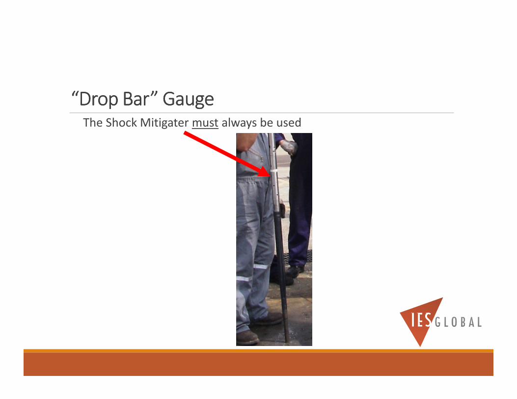
“Drop Bar” Gauge“Drop Bar” Gauge“Drop Bar” Gauge“Drop Bar” GaugeThe Shock Mitigater must always be used

“Drop Bar” Gauge“Drop Bar” Gauge“Drop Bar” Gauge“Drop Bar” GaugeThe Pressure Ports of the Gauge will be in the “nose” of the gauge DROP BAR when the Gauge is dropped.

“Drop Bar” Gauge“Drop Bar” Gauge“Drop Bar” Gauge“Drop Bar” GaugeThe DROP BAR sub is designed to interface with a 5/8” sucker rod firing pin.

“Drop Bar” Gauge“Drop Bar” Gauge“Drop Bar” Gauge“Drop Bar” GaugeThe DROP BAR sub can be purchased or Leased. The sub come as a pair with ordered.
The part number is #IES-DB-58

“Drop Bar” Gauge“Drop Bar” Gauge“Drop Bar” Gauge“Drop Bar” Gauge
Note: The Gauge must be programmed slightly different than normal.
Please contact Scott Ager ([email protected]) for more information concerning your DROP BAR settings and applications.

Gauge SectionsGauge SectionsGauge SectionsGauge Sections

Pressure Port,
Accelerometers
Attaches to Shock Mitigater and
Propellant/Perforating Tool
(Top of the Gauge)
Bull Nose
(Bottom of
Gauge)
Gauge InstallationGauge InstallationGauge InstallationGauge Installation
NOTE: The gauge can be oriented with the pressure
port either up or down.
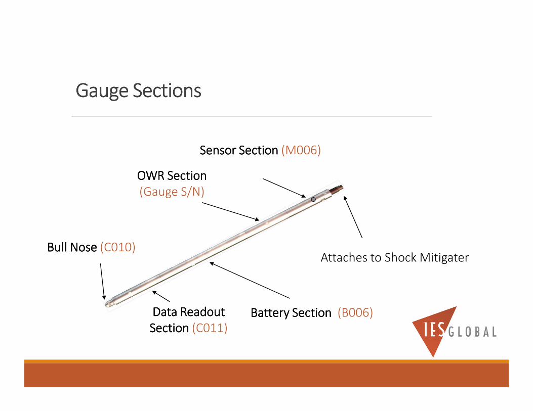
Gauge SectionsGauge SectionsGauge SectionsGauge Sections
Sensor SectionSensor SectionSensor SectionSensor Section (M006)
OWROWROWROWR SectionSectionSectionSection
(Gauge S/N)
Attaches to Shock MitigaterBull NoseBull NoseBull NoseBull Nose (C010)
Battery SectionBattery SectionBattery SectionBattery Section (B006)Data Readout Data Readout Data Readout Data Readout
SectionSectionSectionSection (C011)

Gauge Section Part NumbersGauge Section Part NumbersGauge Section Part NumbersGauge Section Part Numbers
The Serial Number of the Gauge
is stamped in the wrench slots
of the OWR Section.
The Part Number is stamped
into the wrench slots of each
Gauge Section
High Speed Pressure DataHigh Speed Pressure DataHigh Speed Pressure DataHigh Speed Pressure Data

High Speed Pressure DataHigh Speed Pressure DataHigh Speed Pressure DataHigh Speed Pressure Data
Uses of High Speed Gauge Pressure Data
(115,000 data points/ second)
◦ Verify Propellant and Perforating Burn Job Models
◦ Verify Perforating Job Models
◦ Verify Underbalance and Overbalance Pressure Models
◦ Verify Pressures after the guns fire
◦ Measure Reservoir Pressures
◦ Record Tool Movement (Low G Accelerometer option)
◦ Record Tool Impact and Vibration (High G Accelerometer option)

Perforation GunPerforation GunPerforation GunPerforation Gun
High Speed Pressure Data

Dynamic UnderbalanceDynamic UnderbalanceDynamic UnderbalanceDynamic Underbalance
Perforation Event
Dynamic Underbalance

Perforation / Propellant GunPerforation / Propellant GunPerforation / Propellant GunPerforation / Propellant Gun
0.000 0.005 0.010 0.015 0.020 0.025 0.030 0.035 0.040 0.045Time seconds
0
10
20
30
40
50
60
70
80
90
Pre
ssur
e-M
Pa
--- perf gun
-- echo from PB
High Speed Pressure Data

Propellant GunPropellant GunPropellant GunPropellant Gun
0.00 0.05 0.10 0.15 0.20 0.25 0.30 0.35 0.40Time seconds
0
3
6
9
12
15
18
21
24
Pre
ssure
-M
Pa
High Speed data
High Speed Pressure Data
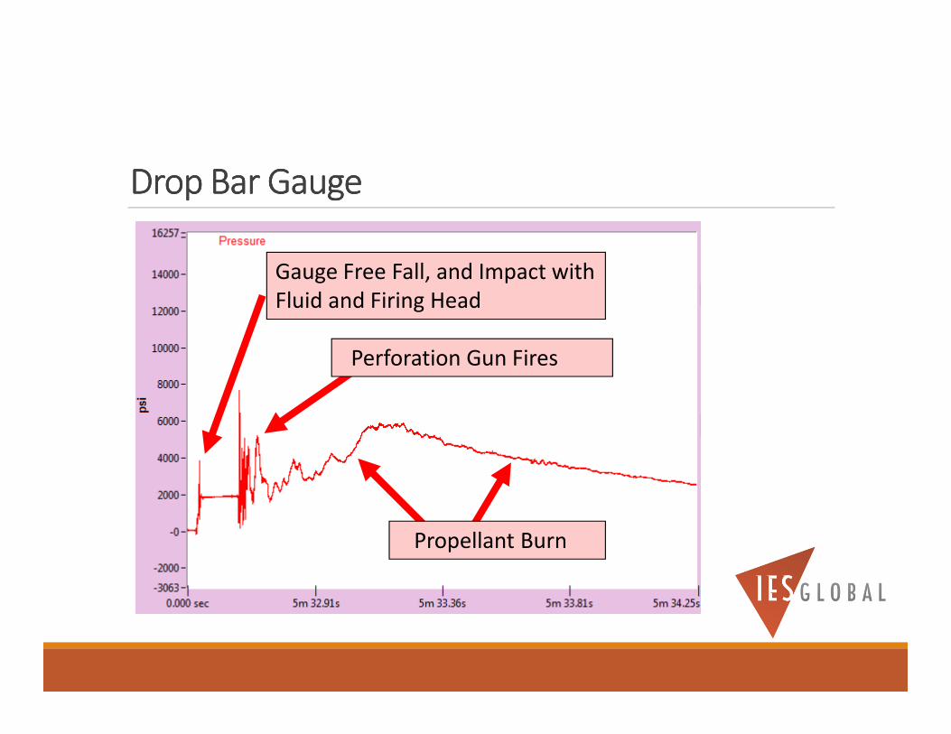
Drop Bar GaugeDrop Bar GaugeDrop Bar GaugeDrop Bar Gauge
Perforation Gun Fires
Propellant Burn
Gauge Free Fall, and Impact with
Fluid and Firing Head

Drop Bar GaugeDrop Bar GaugeDrop Bar GaugeDrop Bar Gauge
Impact with Fluid
Free Fall in Fluid
Free Fall in Air
Impact with
Firing Head

LOW G Accelerometer Data LOW G Accelerometer Data LOW G Accelerometer Data LOW G Accelerometer Data –––– for Tool Movement (Model 400 Only)for Tool Movement (Model 400 Only)for Tool Movement (Model 400 Only)for Tool Movement (Model 400 Only)
Low G Accelerometer Data
High Speed Pressure Data
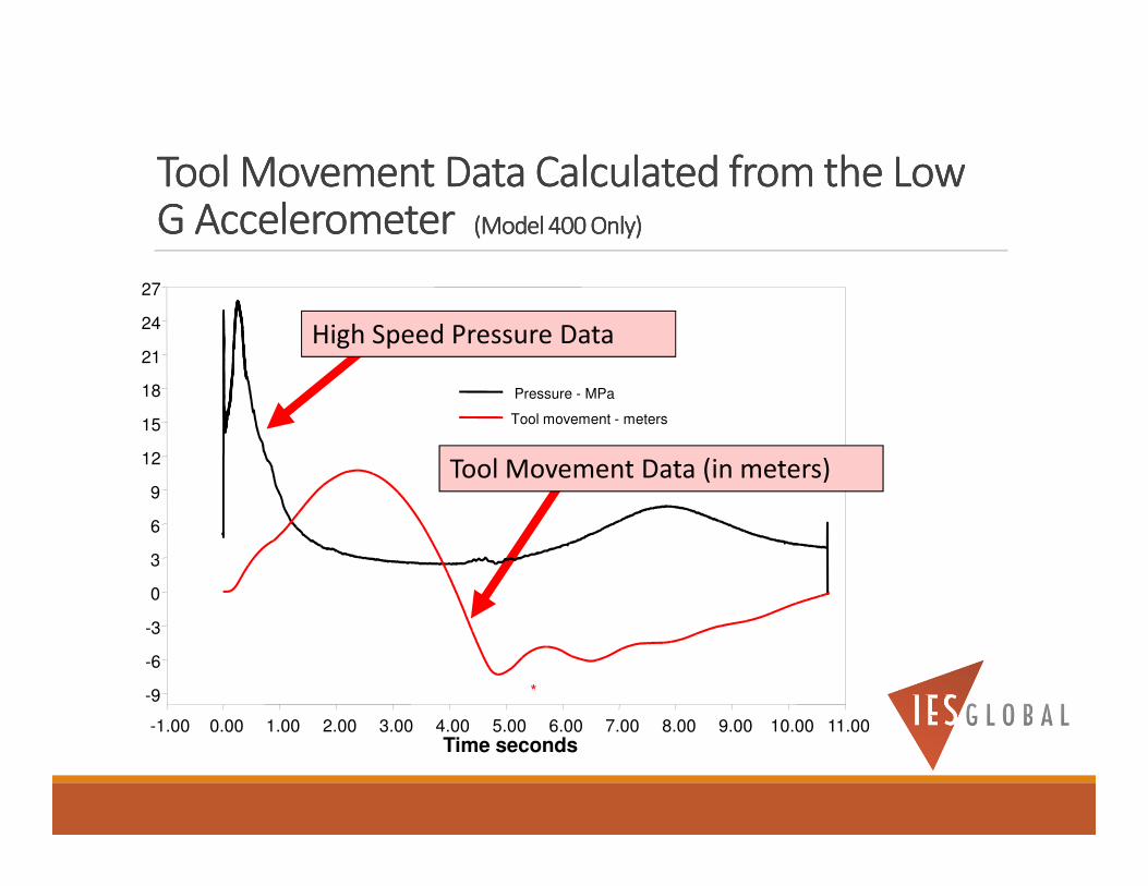
Tool Movement Data Calculated from the Low Tool Movement Data Calculated from the Low Tool Movement Data Calculated from the Low Tool Movement Data Calculated from the Low G Accelerometer G Accelerometer G Accelerometer G Accelerometer (Model 400 Only)(Model 400 Only)(Model 400 Only)(Model 400 Only)
-1.00 0.00 1.00 2.00 3.00 4.00 5.00 6.00 7.00 8.00 9.00 10.00 11.00Time seconds
-9
-6
-3
0
3
6
9
12
15
18
21
24
27
*
Pressure - MPa
Tool movement - meters
High Speed Pressure Data
Tool Movement Data (in meters)
Tool Movement and Velocity Tool Movement and Velocity Tool Movement and Velocity Tool Movement and Velocity Data can be Calculated Data can be Calculated Data can be Calculated Data can be Calculated from the Low G Acceleration Datafrom the Low G Acceleration Datafrom the Low G Acceleration Datafrom the Low G Acceleration Data
If you record Low G acceleration data with the series 400 gauge, you can integrate the data (FAST speed only), and it will give you the Velocity of your tool (feet/sec) vs. time.
If you integrate the Velocity data, that will give you the Distance traveled (feet) vs. time.

HIGH G Accelerometer Data HIGH G Accelerometer Data HIGH G Accelerometer Data HIGH G Accelerometer Data ––––for Tool Vibration for Tool Vibration for Tool Vibration for Tool Vibration (Model 400 Only)(Model 400 Only)(Model 400 Only)(Model 400 Only)
HIGH G Accelerometer
(Vibration) Data
Guns Firing (Pressure Data)

Shock Shock Shock Shock MitigaterMitigaterMitigaterMitigater
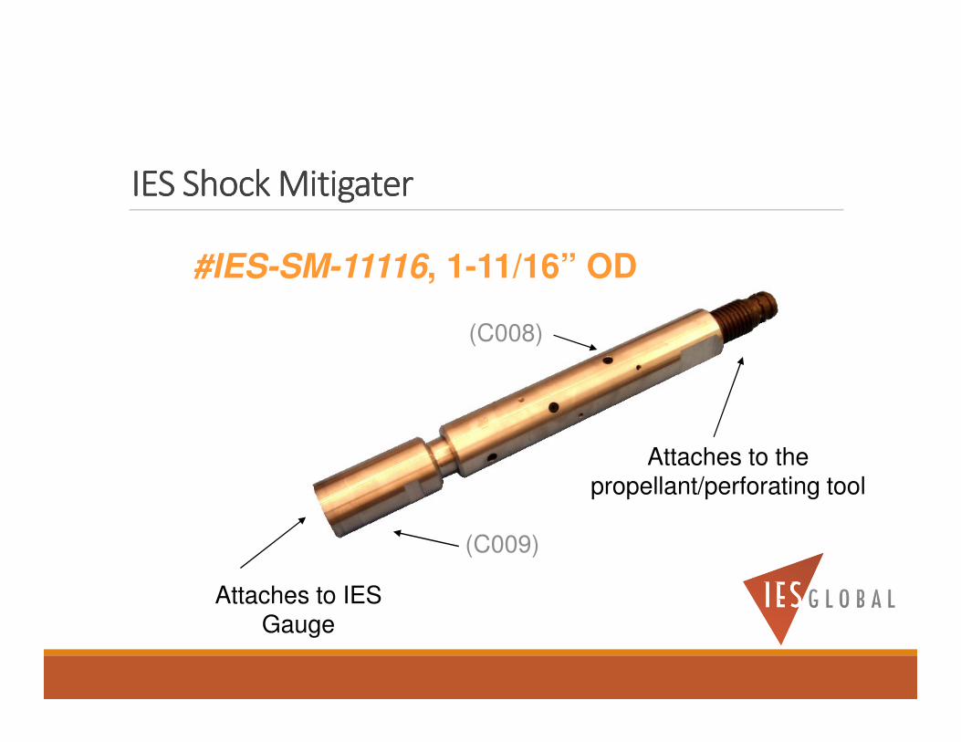
IES Shock IES Shock IES Shock IES Shock MitigaterMitigaterMitigaterMitigater
Attaches to IES Gauge
Attaches to the propellant/perforating tool
#IES-SM-11116, 1-11/16” OD
(C009)
(C008)

IES Shock MitigaterIES Shock MitigaterIES Shock MitigaterIES Shock Mitigater
� USE is STRONLY RECOMMENDED
� Placed between the Gauge and the propellant/perforating tool
(NOTE: A “centralizer” must be used on the tool)
� Reduces the shock and vibration along the vertical axis by up to 10 times…
� Increases the life of the Gauge, OWR, sensors, and battery

IES Shock Mitigater LocationIES Shock Mitigater LocationIES Shock Mitigater LocationIES Shock Mitigater Location
IES Gauge
Pressure Port
IES Shock Mitigater
Centralizer
Propellant Tool(Top)
(Bottom)
Place the Shock Mitigater
between the Gauge, and the
Gun or Gauge Carrier

Battery FixtureBattery FixtureBattery FixtureBattery Fixture
(LOCATED INSIDE THE BAT TERY SECTION)

Battery FixtureBattery FixtureBattery FixtureBattery Fixture(Located inside the Battery Section)
IES Potted Battery Pack
Installed“Red Kill Switch”

Battery FixtureBattery FixtureBattery FixtureBattery Fixture
The Battery Fixture is used to hold the Battery Pack. ◦ It is located inside the BATTERY SECTION of the gauge (between the OWR Section and
the Date Readout Section).
One or Two Batteries can be used with a Gauge◦ It is STRONGLY recommended that you always run TWO batteries per gauge for
redunancy
◦ An addition Battery extends the time downhole, and provides a backup battery
◦ An extra Battery Fixture, Battery Pack, and Battery Section is required for running TWO batteries.
◦ When using two batteries, the length of the gauge is increased by 17.5 inches
Always use the Lithium Battery Packs supplied by IES. ◦ They are specifically designed for the IES gauge in a High Shock Environment.
Battery Fixture “Types”Battery Fixture “Types”Battery Fixture “Types”Battery Fixture “Types”
There are TWO Types of Battery Fixtures available.◦ The 120°C Gauge comes with the #IES-BAT-005 Battery Fixture
◦ The 150°C and 175°C Gauge comes with the #IES-BAT-006* Battery Fixture
*When using the Series 400 Gauge, use the #IES-BAT-006 battery fixture.
Additional Battery Fixtures can be purchased or Leased.

Battery Fixture “Types”Battery Fixture “Types”Battery Fixture “Types”Battery Fixture “Types”
#IES-BAT-005 Battery Fixture (120°C).
◦ DO NOT USE for 150°C applications!
◦ Can be used with 80°C Alkaline or 120°C/150°C/180°C Lithium Battery Packs.

Battery Fixture “Types”Battery Fixture “Types”Battery Fixture “Types”Battery Fixture “Types”
#IES-BAT-006 Lithium Battery Fixture (180°C).
◦ Can be used with all Series 300 and Series 400 Gauges
◦ Can ONLY be use with the 120°C, 150°C, or 180°C Lithium Battery Pack!
◦ DO NOT use with the Alkaline Battery Packs!

Battery Pack OptionsBattery Pack OptionsBattery Pack OptionsBattery Pack Options

Alkaline and Lithium Alkaline and Lithium Alkaline and Lithium Alkaline and Lithium Battery PacksBattery PacksBattery PacksBattery Packs
The 80°C Alkaline (not for use with the Series 400 gauge), 120°C Lithium, 150°C Lithium, and 180°C Lithium BatteryPacks are all packaged inside a BLACK or dark colored tube.
Note: Be sure to read the Labeling on the Battery Pack so you know which Battery Pack you are using.

Battery Pack OptionsBattery Pack OptionsBattery Pack OptionsBattery Pack Options
* Lithium battery packs CANNOT be used with the Series 200 gauges.
80°C Alkaline Battery Pack
◦ #IES-BAT-BA2C
120°C Lithium Battery Pack
◦ #IES-BAT-BL32AA120
150°C Lithium Battery Pack
◦ #IES-BAT-BL32AA150 (for the Series 300)
◦ #IES-BAT-BL02AA150 (for the Series 400 ONLY)
◦ #IES-BAT-BL22AA150 - Double Power (for the Series 400 ONLY)
180°C Lithium Battery Pack (use only above 80°C)
◦ #IES-BAT-BL02AA180 (for the Series 400 ONLY)
◦ #IES-BAT-BL22AA180 - Double Power (for the Series 400 ONLY)

IES Fast Speed GaugesIES Fast Speed GaugesIES Fast Speed GaugesIES Fast Speed Gauges


