If you have been around Spicer driveline products for any length of time, you know that Dana engineers have ALWAYS talked about how U-joint operating angles can cause torsional and inertial effects that can damage many of the driveline components in a vehicle. Since U-joint operating angles are typically created during the design of a new vehicle, you can assume that vehicles do not leave the factory with vibration problems causes by improper U- joint operating angles. What happens is… Parts wear. Suspensions wear. Air bags somehow get out of adjustment or may even fail, causing vehicle heights’ to change… which causes operating angles to change. PLUS….businesses may modify a vehicle’s wheelbase by shortening or lengthening it from the OEM’s original specification, inadvertently changing operating angles. This program will provide you with a means of checking a vehicle’s driveline installation for torsional, and inertial problems…right in your office, ON YOUR OFFICE COMPUTER. When you enter driveline installation data into the program’s calculation fields, it will, with a couple of clicks of the mouse, perform an instant torsional and inertial analysis on the data you enter. Ordinarily, you would probably have to go to your garage and add a few shims between the frame and axle, then drive the vehicle to see if it still vibrates and if it does, bring it back into the garage and repeat the process, over and over again, until you get the best results. With this program, you can sit right at your computer and revise the original data, and, if you understand U-joint operating angles, correct the problem, without having to get up out of your chair. You can make whatever changes are necessary, as many times as necessary, to eliminate all torsional and inertial vibrations. The first thing you will need is a GOOD SET of initial data: You will need to measure all angles with an accurate protractor…PREFERRABLY A DIGITAL PROTRACTOR. You will need to be able to understand what a SLOPE is. And you will need to be able to ACCURATELY MEASURE LENGTHS. YOU WILL HAVE TO DETERMINE ALL OF THE FOLLOWING: 1. Maximum drive shaft RPM. Determined by dividing engine RPM by the lowest transmission ratio. 2. The angle and slope of the driving member. (In a vehicle, usually a transmission) 3. The angle and slope of all of the drive shafts in the application. 4. The length from center of u-joint to center of u-joint of all of the drive shafts in the application, in inches. (Ex: 35.00) 5. The angle and slope of the driven member. (In a truck, usually an axle) 6. The offset of any, or all, components when looking down from the top. (Ex: 3.00) Note: Measure all angles, and determine all slopes, from the driver’s side of the vehicle. The definition of slope: If the rear of a component is LOWER than the front of the component, it is a DOWN slope. (Most transmissions slope down) If the rear of a component is HIGHER than the front of the component, it is a UP slope. (CAUTION: Most axles have an end yoke that points UP, but since the rear of the axle is usually lower than the front of the axle, it is, for the purpose of this program, a DOWN slope).
Transcript
If you have been around Spicer driveline products for any length of time, you know that Dana engineers have ALWAYS talked about how U-joint operating angles can cause torsional and inertial effects that can damage many of the driveline components in a vehicle. Since U-joint operating angles are typically created during the design of a new vehicle, you can assume that vehicles do not leave the factory with vibration problems causes by improper U-joint operating angles. What happens is… Parts wear. Suspensions wear. Air bags somehow get out of adjustment or may even fail, causing vehicle heights’ to change… which causes operating angles to change. PLUS….businesses may modify a vehicle’s wheelbase by shortening or lengthening it from the OEM’s original specification, inadvertently changing operating angles. This program will provide you with a means of checking a vehicle’s driveline installation for torsional, and inertial problems…right in your office, ON YOUR OFFICE COMPUTER. When you enter driveline installation data into the program’s calculation fields, it will, with a couple of clicks of the mouse, perform an instant torsional and inertial analysis on the data you enter. Ordinarily, you would probably have to go to your garage and add a few shims between the frame and axle, then drive the vehicle to see if it still vibrates and if it does, bring it back into the garage and repeat the process, over and over again, until you get the best results. With this program, you can sit right at your computer and revise the original data, and, if you understand U-joint operating angles, correct the problem, without having to get up out of your chair. You can make whatever changes are necessary, as many times as necessary, to eliminate all torsional and inertial vibrations. The first thing you will need is a GOOD SET of initial data:
You will need to measure all angles with an accurate protractor…PREFERRABLY A DIGITAL PROTRACTOR. You will need to be able to understand what a SLOPE is. And you will need to be able to ACCURATELY MEASURE LENGTHS.
YOU WILL HAVE TO DETERMINE ALL OF THE FOLLOWING:
1. Maximum drive shaft RPM. Determined by dividing engine RPM by the lowest transmission ratio.
2. The angle and slope of the driving member. (In a vehicle, usually a transmission) 3. The angle and slope of all of the drive shafts in the application.
4. The length from center of u-joint to center of u-joint of all of the drive shafts in the application, in inches. (Ex: 35.00)
5. The angle and slope of the driven member. (In a truck, usually an axle) 6. The offset of any, or all, components when looking down from the top. (Ex: 3.00)
Note: Measure all angles, and determine all slopes, from the driver’s side of the vehicle. The definition of slope: If the rear of a component is LOWER than the front of the component, it is a DOWN slope. (Most transmissions slope down) If the rear of a component is HIGHER than the front of the component, it is a UP slope.
(CAUTION: Most axles have an end yoke that points UP, but since the rear of the axle is usually lower than the front of the axle, it is, for the purpose of this program, a DOWN slope).
Write down the angle and length with an arrow showing direction of slope. (Ex: 3↓) Here’s how the program works:
The usual driveline set-up in a truck consists of a transmission, which is usually attached to a driveshaft, which is usually attached to an axle. All three of these components usually have a down slope. In an ideal set-up, those component angles and slopes do not create u-joint angles large enough to cause a torsional or inertia problem.
The program will take the data you measure from an existing vehicle and calculate torsional and inertia levels and will determine if there is a problem. It will provide an alert, in the form of RED lettering on the data screen, if something is wrong. If the program identifies a problem, you can quickly go back into the program and make modifications to the set-up in an attempt to remedy the problem. Typically, the corrective procedure involves shimming the axle to change the angle of the axle. This change to the axle angle will change the angle of the driveshaft, because the driveshaft is attached to the axle.
The program will then re-calculate the data, and send another alert, if necessary.
If additional modifications are required, you can go back into the program again, and re-adjust the data again, (usually by rotating the axle again), and re-analyze again. And continue to do that over and over until you get the results you want.
Your goal…to get torsional results and inertia results as near to ZERO as possible. Before we start the tutorial, here are some VERY important points you have to understand to make the program work properly: 1. You will enter your existing vehicle data and CLICK CALCULATE TORSIONALS. 2. If you notice a mistake in your data entries, BEFORE you click CALCULATE TORSIONALS, you
can type over it and change it. 3. If you calculate torsionals and they are too high, you MUST click the BACK button, on the bottom
of the torsional data screen to go back and make revisions. DO NOT CLICK THE BACK ARROW AT THE TOP OF YOUR COMPUTER SCREEN.
4. After you go back, you can ONLY change certain data, based on the type of vehicle data you have entered:
a. On a one shaft vehicle, you can ONLY change the angle of the driven member, you cannot change the angle of the driving member because it is “fixed” in the vehicle, OR the drive shaft because it is attached to the driven member and “moves’ with any changes in the angle of the driven member.
b. On a multi shaft vehicle, you cannot change the angle of the driving member OR the REAR MOST drive shaft because it is attached to the driven member and “moves’ with any changes in the angle of the driven member. However, you CAN change the angles of any drive shafts in front of the rear most shaft…and you usually do that by adding or removing shims from under center bearings.
5. EVERY time you change something, you should HIT ENTER before you CLICK Calculate torsionals. Hitting ENTER locks your new data into the program.
6. You can CLICK back and go back and change data as many times as you want to, but you mUST always hit enter and calculate torsionals BEFORE you CLICK back.
7. At any time, and after doing anything, you can CLICK RESTORE..but you have to remember, RESTORE takes you back to the very beginning and you have to re-enter all data from step one.
This tutorial will “walk” you thru the use of the program for a typical vehicle with one driveshaft, and a typical vehicle with a two drive shafts. It also contains examples, and multi-part tests that will help you learn a little bit about the program.
(Let’s do an application for a typical one-shaft vehicle and use the figures below as though they are the data you measured from your vehicle.) Open the program: On the first page: Enter the data you measured from the actual vehicle. ENTER: No. of shafts….1 CLICK: Heavy Duty ENTER: Driveshaft RPM ….3600 ENTER: Shaft 1 angle, Slope and Length (4 degrees, DOWN slope, 48” long) ENTER: Driver angle and slope (7 degrees, DOWN slope) ENTER: Driven angle and slope (12 degrees, DOWN slope) CLICK: CALCULATE TORSIONALS (If you remember what we have always told you regarding U-joint operating angles, 7-4=3 degrees at the drive end 12-4=8 degrees at the driven end You can see that these angles are VERY large and VERY unequal.) SO….you should expect to see VERY large inertia and VERY large torsional results. Here’s what the screen should look like BEFORE you do the calculation.
When finished: CLICK: Calculate Torsionals This is what the data screen looks like. Note that it shows that the inertia AND torsional results are WAY over our recommendations. (And note that the printing is in RED.)
We’re going to try to fix the problems by using the program. Analyze the data first: Look at what the data is telling you. The torsionals are “out of sight”. (Torsionals are caused by LARGE U-joint operating angles) AND the inertias are VERY large on the driven end. That should tell you that the problem may lie with the operating angle at the driven end of your drivetrain. So…Let’s go back into the program and change the angle at the driven end of the drive shaft by rotating the driven member.
CLICK: Back Change the angle of the driven member to 10 degrees and HIT: enter
Look at the new angle data. You changed the driven member angle to 10 degrees and the drive shaft changed angle. (That’s because there is a trigonometry calculation built into the program that uses drive shaft angle and drive shaft length to re-calculate the new drive shaft angle.)
CLICK: Calculate Torsionals
LOOK at what happened to the data…. Inertia effects on the driven end came down…AND, MORE IMPORTANTLY…Torsionals came down. We’re on the right track, BUT, they are still too high. So…Lets “tweak” the driven member angle again. Let’s change it to 7.5 degrees. CLICK: Back CHANGE the driven member angle to 7.5 degrees and… HIT: enter
NOTE: The angle of the driveshaft changed CLICK: Calculate Torsionals
WOW! Look at the data now…….ALMOST PERFECT. If you remember what Spicer has always said about angles. The smaller the angle, the smaller the inertia vibrations…AND…. The closer the operating angles at each end of a driveshaft are to being equal, the smaller the torsional vibrations. That’s why torsionals are so good. We have almost equal angles on both ends.
You COULD QUIT at this point, but let’s try one more thing. Let’s purposely make the operating angles on each end of the driveshaft EXACTLY equal. BY MAKING THE ANGLE OF THE DRIVER AND THE ANGLE OF THE DRIVEN MEMBER EXACTLY THE SAME. 7 degrees CLICK: Back CHANGE: The driven member angle to 7 degrees HIT: Enter
CLICK: Calculate Torsionals
Note that torsionals are ZERO.
That’s because we have the exact same operating angle at each end of our driveshaft.
AND, we have the exact same operating angle because we have our driver member and our
driven member at the exact same angle.
So, a key thing to remember…if you have the driver and driven members at the same angle,
your torsionals will ALWAYS be ZERO.
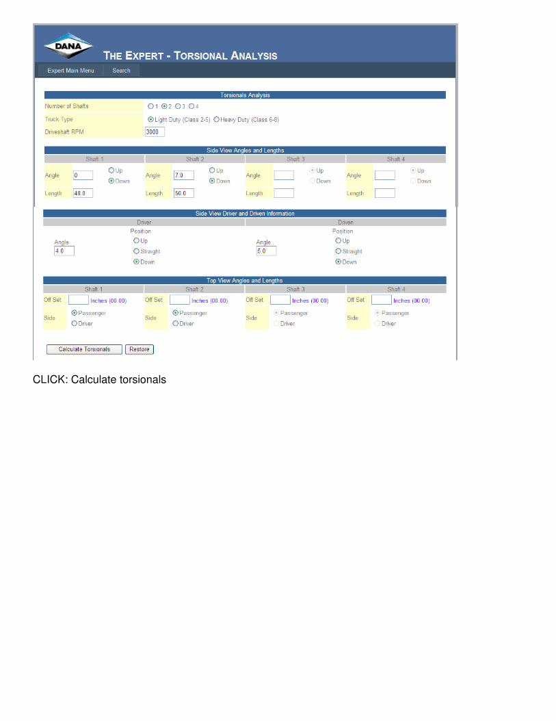
Let’s do an application for a typical two-shaft vehicle and use the figures below as though they are the data you measured from your vehicle. (We’re going to pretend we have a vehicle with a new vibration problem and that someone had removed the shafts from this vehicle and re-installed the first shaft…inadvertently leaving out the center bearing shims.) We’ll check the torsionals on the vehicle the way it is sitting, then go back and put the shims back in and check it again. It should be OK. This will be the data that you measured on the actual vehicle: (Without the shims) No. of shafts: 2 Type: LD RPM of shafts: 3000 Angle of first shaft: 0 degrees DOWN, 40” long (Note: Slope is immaterial when you enter a zero degree
angle)
Angle of second shaft: 7 degrees, DOWN, 50” long Driving member angle: 4 degrees, DOWN Angle of driven member: 5 degrees, DOWN
CLICK: Calculate torsionals
Note that torsionals are high and the inertia effects at the driven end of the shaft are excessive.
That should tell you that your angles are not cancelled and your operating angle at the driven
end of your shaft is probably too large.
Let’s go back and try to fix the problem by adding shims under the center bearing. That will
lower the rear of the first shaft, which will lower the angle of the second shaft, which will lower
the operating angle at the driven member.
We’ll put in shims that will make the angle of the first shaft 3 ½ degrees.
CLICK: Back
Let’s add a couple of shims between the center bearing bracket and cross member until the
angle of the shaft is 3.5, DOWN.
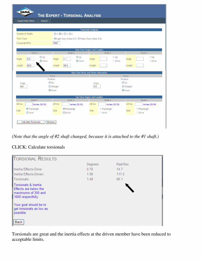
CHANGE: Shaft #1 angle to 3.5 Down
HIT: Enter
(Note that the angle of #2 shaft changed, because it is attached to the #1 shaft.)
CLICK: Calculate torsionals
Torsionals are great and the inertia effects at the driven member have been reduced to