37
www.ifbautomotive.com IFB Automotive Private Limited : CAE Division CAE Safety and Comfort is Our Concern
www.ifbautomotive.com
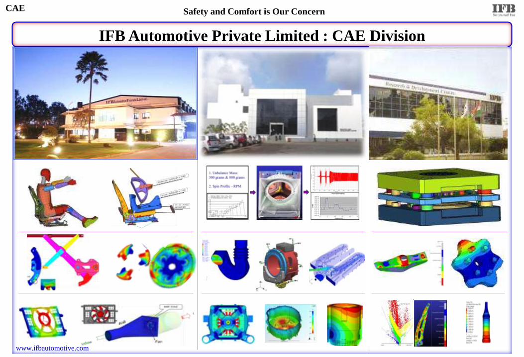
IFB Automotive Private Limited : CAE Division
CAE Safety and Comfort is Our Concern

1974 ▶ IFB INDUSTRIES, KOLKATA Main Products: Fine blanking Components & Sub-assemblies
1984 ▶ IFB INDUSTRIES, BANGALORE Main Products: Fine blanking & Automotive Sub-assemblies
1989 ▶ IFB AUTOMOTIVE PRIVATE LIMITED, BANGALORE Main Products: Seat, Door , Latch Mechanisms & Automotive Motors
1990 ▶ IFB HOME APPLIANCES , GOA Main Products: Washing m/c, Dish washer, Micro wave Oven, A/C, Refrigerator
2003
▶ IFB AUTOMOTIVE R&D
CENTER.- BANGALORE
2005 ▶ IFB AUTOMOTIVE, CHENNAI 2007 ▶ IFB AUTOMOTIVE, PUNE ▶ IFB AUTOMOTIVE, UTTARAKAND
2007
▶ IFB AUTOMOTIVE, BINOLA Satellite plant of IFB APL Bangalore
2012
▶ IFB APL : CAE Division Analysis/Simulations: NVH, MBD, CFD, FE-Structure, Manufacturing & Optimization
CAE Safety and Comfort is Our Concern

IFB’s Domain Expertise
Country spirit Packed Sea Food
IFB AGRO
Fine Blanking
Tools Fine Blanking
Components
IFB INDUSTRIES
IFB HOME APPLIANCES
Washing machine Refrigerator Dryer
Air conditions Micro-wave Dish washer
IFB AUTOMOTIVE
Seating Systems Door Systems
Latches Motors
CAE
Automotive Door
Systems
Automotive Seating
Systems Motors
Home Appliance
Products
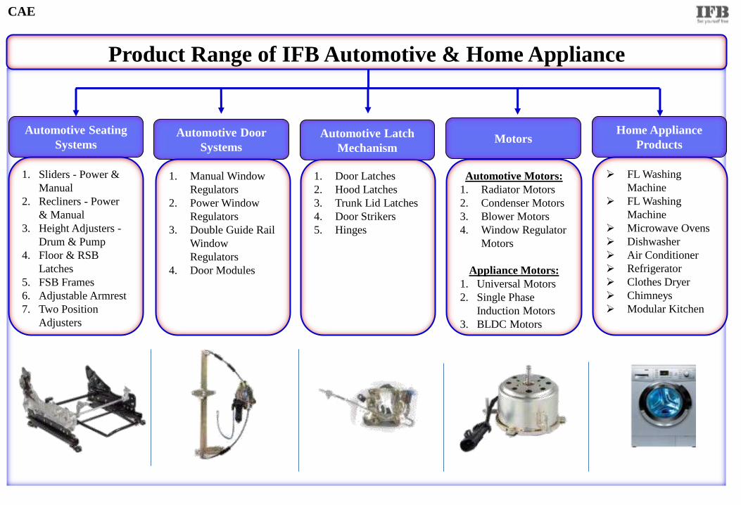
1. Sliders - Power &
Manual
2. Recliners - Power
& Manual
3. Height Adjusters -
Drum & Pump
4. Floor & RSB
Latches
5. FSB Frames
6. Adjustable Armrest
7. Two Position
Adjusters
1. Manual Window
Regulators
2. Power Window
Regulators
3. Double Guide Rail
Window
Regulators
4. Door Modules
Automotive Motors:
1. Radiator Motors
2. Condenser Motors
3. Blower Motors
4. Window Regulator
Motors
Appliance Motors:
1. Universal Motors
2. Single Phase
Induction Motors
3. BLDC Motors
1. Door Latches
2. Hood Latches
3. Trunk Lid Latches
4. Door Strikers
5. Hinges
Automotive Latch
Mechanism
FL Washing
Machine
FL Washing
Machine
Microwave Ovens
Dishwasher
Air Conditioner
Refrigerator
Clothes Dryer
Chimneys
Modular Kitchen
Product Range of IFB Automotive & Home Appliance
CAE
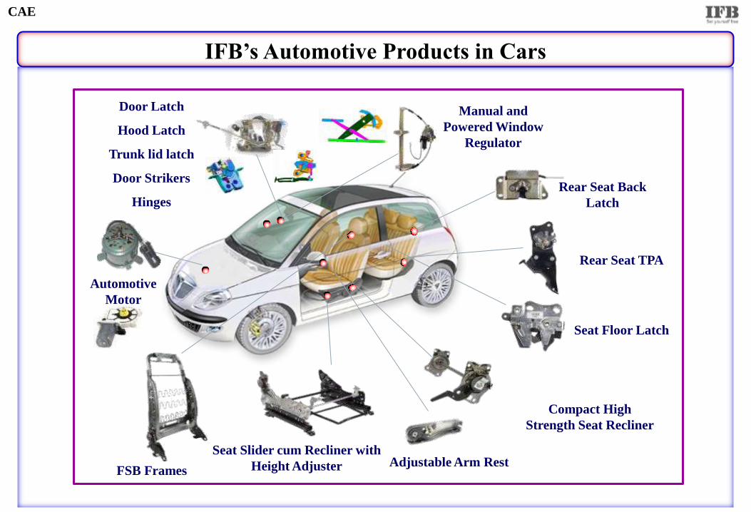
IFB’s Automotive Products in Cars
Rear Seat Back
Latch
Seat Slider cum Recliner with
Height Adjuster
Compact High
Strength Seat Recliner
Seat Floor Latch
Rear Seat TPA
Manual and
Powered Window
Regulator
Door Latch
Hood Latch
Trunk lid latch
Door Strikers
Hinges
FSB Frames Adjustable Arm Rest
Automotive
Motor
CAE
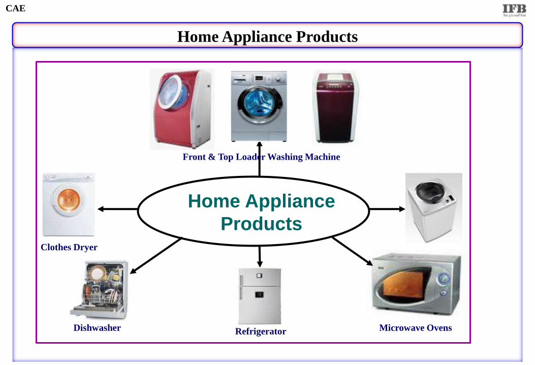
Home Appliance Products
Home Appliance
Products
Front & Top Loader Washing Machine
Refrigerator Microwave Ovens Dishwasher
Clothes Dryer
CAE
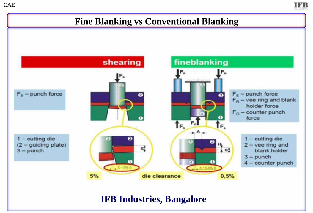
Fine Blanking vs Conventional Blanking
CAE
IFB Industries, Bangalore
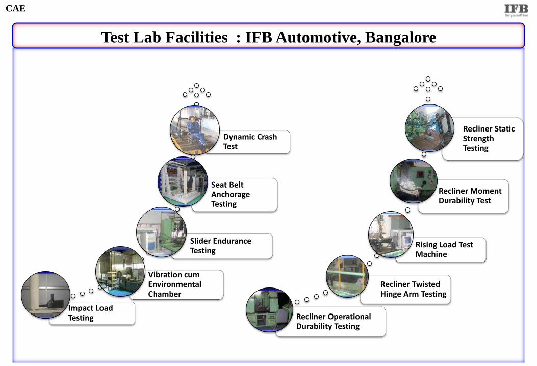
Test Lab Facilities : IFB Automotive, Bangalore
Impact Load Testing
Vibration cum Environmental Chamber
Slider Endurance Testing
Seat Belt Anchorage Testing
Dynamic Crash Test
Recliner Operational Durability Testing
Recliner Twisted Hinge Arm Testing
Rising Load Test Machine
Recliner Moment Durability Test
Recliner Static Strength Testing
CAE
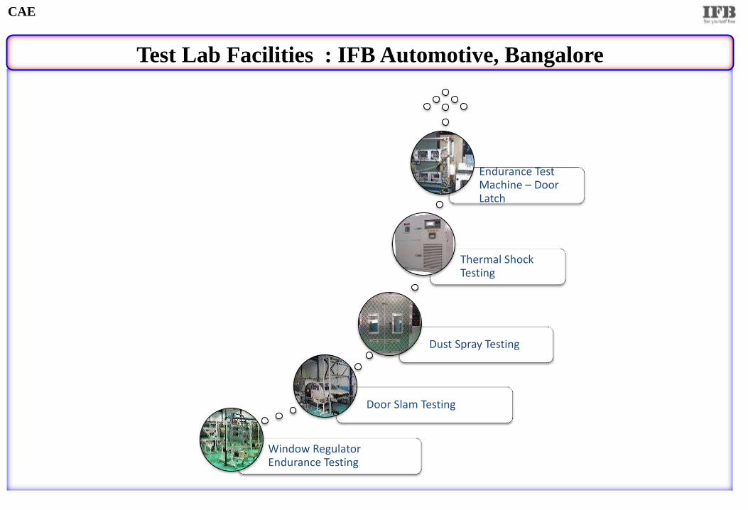
Test Lab Facilities : IFB Automotive, Bangalore
Window Regulator Endurance Testing
Door Slam Testing
Dust Spray Testing
Thermal Shock Testing
Endurance Test Machine – Door Latch
CAE

Test Lab Facilities : IFB Home Appliance, Goa
Mechanical Testing Lab
Environmental Test Rooms Safety Test Lab EMI/EMC testing Lab
CAE
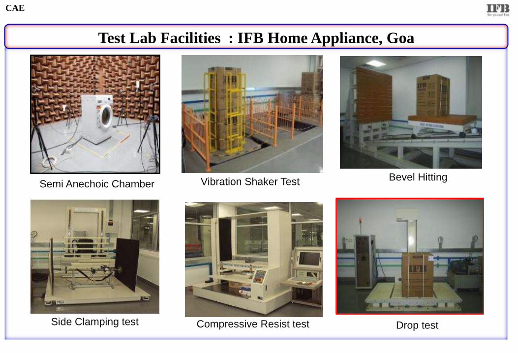
Test Lab Facilities : IFB Home Appliance, Goa
Vibration Shaker Test Bevel Hitting
Side Clamping test Drop test Compressive Resist test
Semi Anechoic Chamber
CAE
IFB CAE - Predictive Engineering
Computer Aided Engineering (CAE)
CAE
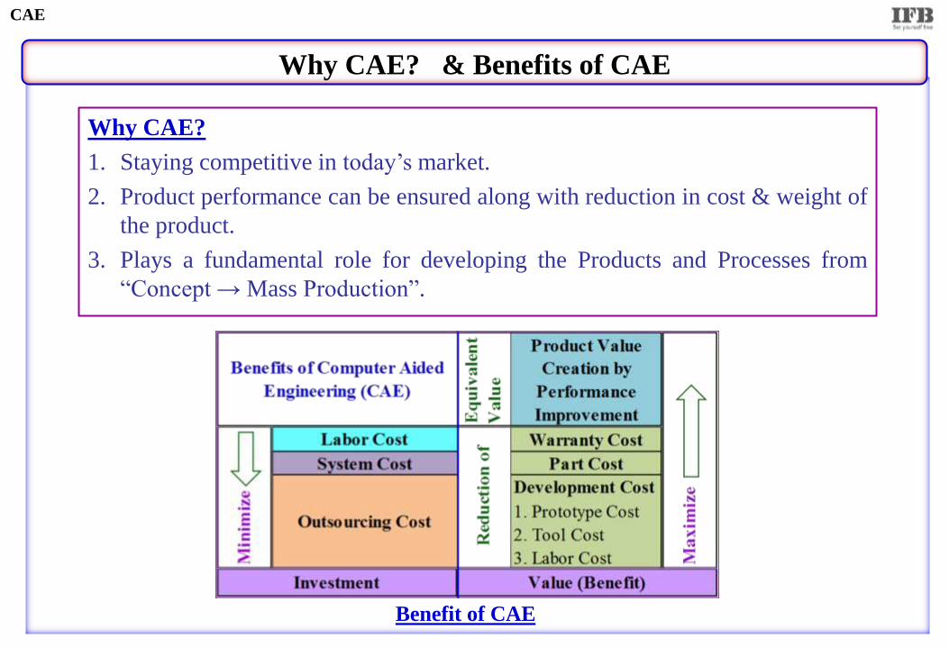
Why CAE? & Benefits of CAE
Why CAE?
1. Staying competitive in today’s market.
2. Product performance can be ensured along with reduction in cost & weight of
the product.
3. Plays a fundamental role for developing the Products and Processes from
“Concept → Mass Production”.
CAE
Benefit of CAE
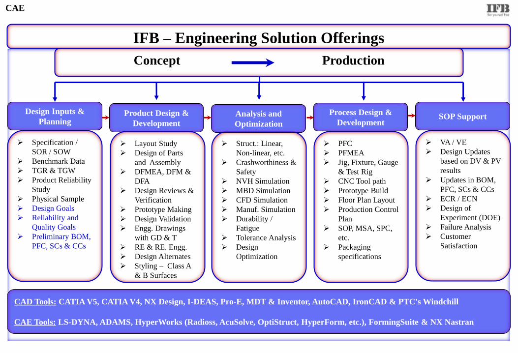
Product Design &
Development
Design Inputs &
Planning Process Design &
Development SOP Support
Specification /
SOR / SOW
Benchmark Data
TGR & TGW
Product Reliability
Study
Physical Sample
Design Goals
Reliability and
Quality Goals
Preliminary BOM,
PFC, SCs & CCs
Layout Study
Design of Parts
and Assembly
DFMEA, DFM &
DFA
Design Reviews &
Verification
Prototype Making
Design Validation
Engg. Drawings
with GD & T
RE & RE. Engg.
Design Alternates
Styling – Class A
& B Surfaces
Concept Production
PFC
PFMEA
Jig, Fixture, Gauge
& Test Rig
CNC Tool path
Prototype Build
Floor Plan Layout
Production Control
Plan
SOP, MSA, SPC,
etc.
Packaging
specifications
Struct.: Linear,
Non-linear, etc.
Crashworthiness &
Safety
NVH Simulation
MBD Simulation
CFD Simulation
Manuf. Simulation
Durability /
Fatigue
Tolerance Analysis
Design
Optimization
Analysis and
Optimization
VA / VE
Design Updates
based on DV & PV
results
Updates in BOM,
PFC, SCs & CCs
ECR / ECN
Design of
Experiment (DOE)
Failure Analysis
Customer
Satisfaction
CAD Tools: CATIA V5, CATIA V4, NX Design, I-DEAS, Pro-E, MDT & Inventor, AutoCAD, IronCAD & PTC's Windchill
CAE Tools: LS-DYNA, ADAMS, HyperWorks (Radioss, AcuSolve, OptiStruct, HyperForm, etc.), FormingSuite & NX Nastran
IFB – Engineering Solution Offerings
CAE
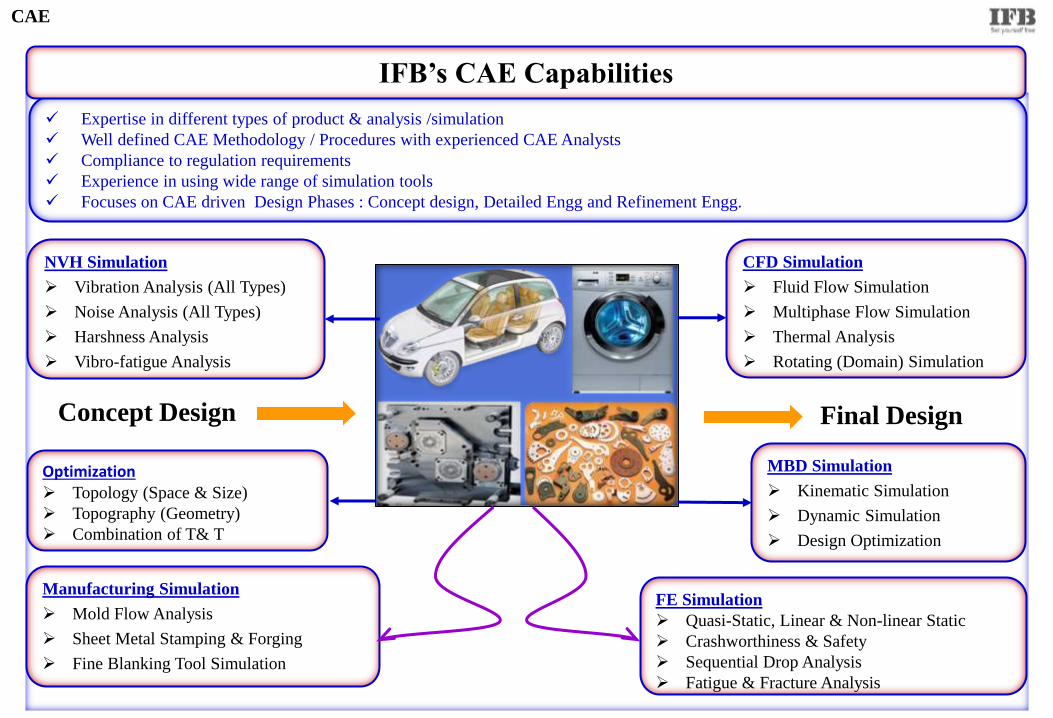
FE Simulation
Quasi-Static, Linear & Non-linear Static
Crashworthiness & Safety
Sequential Drop Analysis
Fatigue & Fracture Analysis
Manufacturing Simulation
Mold Flow Analysis
Sheet Metal Stamping & Forging
Fine Blanking Tool Simulation
CFD Simulation
Fluid Flow Simulation
Multiphase Flow Simulation
Thermal Analysis
Rotating (Domain) Simulation
Optimization Topology (Space & Size)
Topography (Geometry)
Combination of T& T
MBD Simulation
Kinematic Simulation
Dynamic Simulation
Design Optimization
NVH Simulation
Vibration Analysis (All Types)
Noise Analysis (All Types)
Harshness Analysis
Vibro-fatigue Analysis
Concept Design Final Design
Expertise in different types of product & analysis /simulation
Well defined CAE Methodology / Procedures with experienced CAE Analysts
Compliance to regulation requirements
Experience in using wide range of simulation tools
Focuses on CAE driven Design Phases : Concept design, Detailed Engg and Refinement Engg.
IFB’s CAE Capabilities
CAE
IFB CAE - Predictive Engineering
CAE Case Studies
Automotive & Home Appliance Products
CAE
CAE
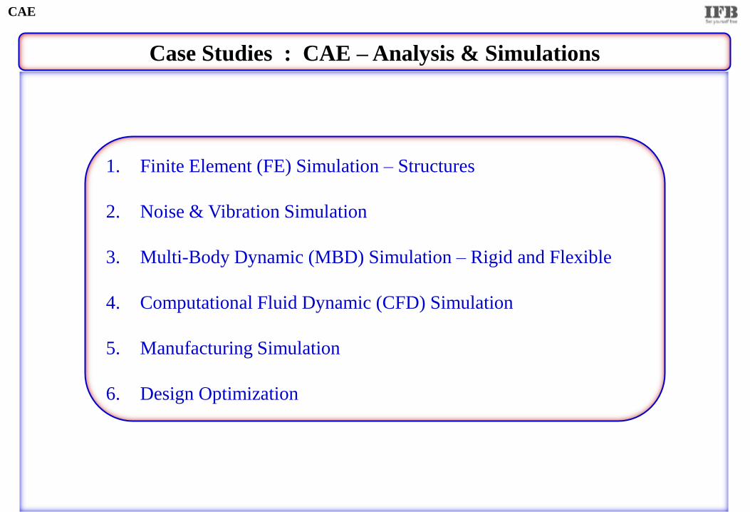
Case Studies : CAE – Analysis & Simulations
1. Finite Element (FE) Simulation – Structures
2. Noise & Vibration Simulation
3. Multi-Body Dynamic (MBD) Simulation – Rigid and Flexible
4. Computational Fluid Dynamic (CFD) Simulation
5. Manufacturing Simulation
6. Design Optimization
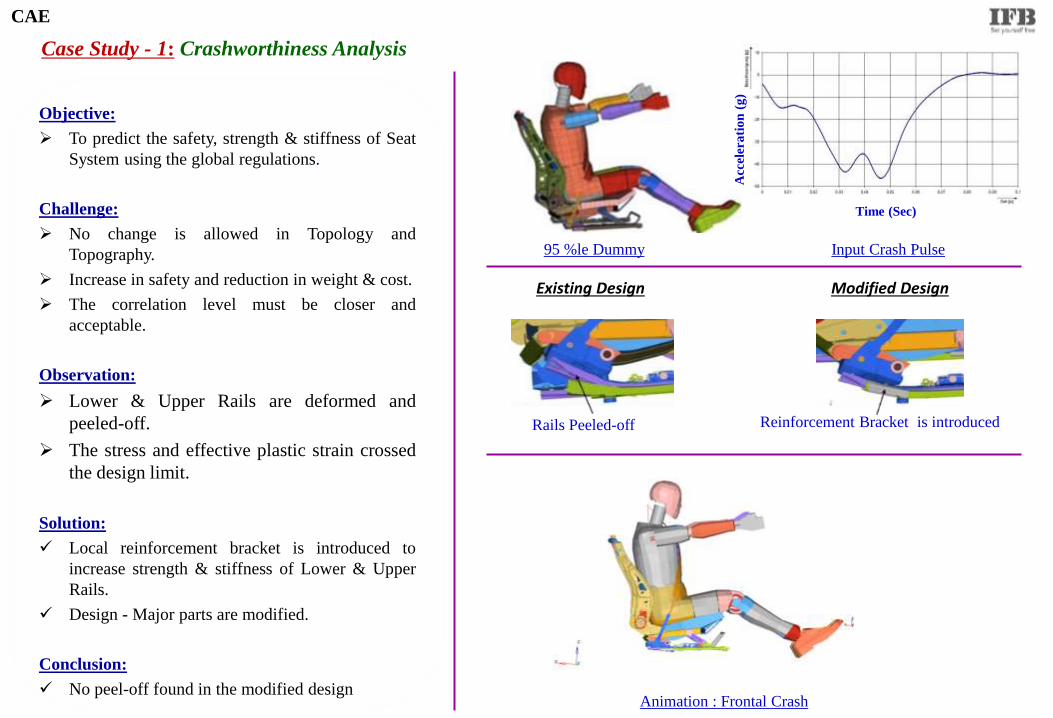
Objective:
To predict the safety, strength & stiffness of Seat
System using the global regulations.
Challenge:
No change is allowed in Topology and
Topography.
Increase in safety and reduction in weight & cost.
The correlation level must be closer and
acceptable.
Observation:
Lower & Upper Rails are deformed and
peeled-off.
The stress and effective plastic strain crossed
the design limit.
Solution:
Local reinforcement bracket is introduced to
increase strength & stiffness of Lower & Upper
Rails.
Design - Major parts are modified.
Conclusion:
No peel-off found in the modified design
Case Study - 1: Crashworthiness Analysis
95 %le Dummy Input Crash Pulse
Rails Peeled-off Reinforcement Bracket is introduced
Animation : Frontal Crash
Existing Design Modified Design
Acc
eler
ati
on
(g
)
Time (Sec)
CAE
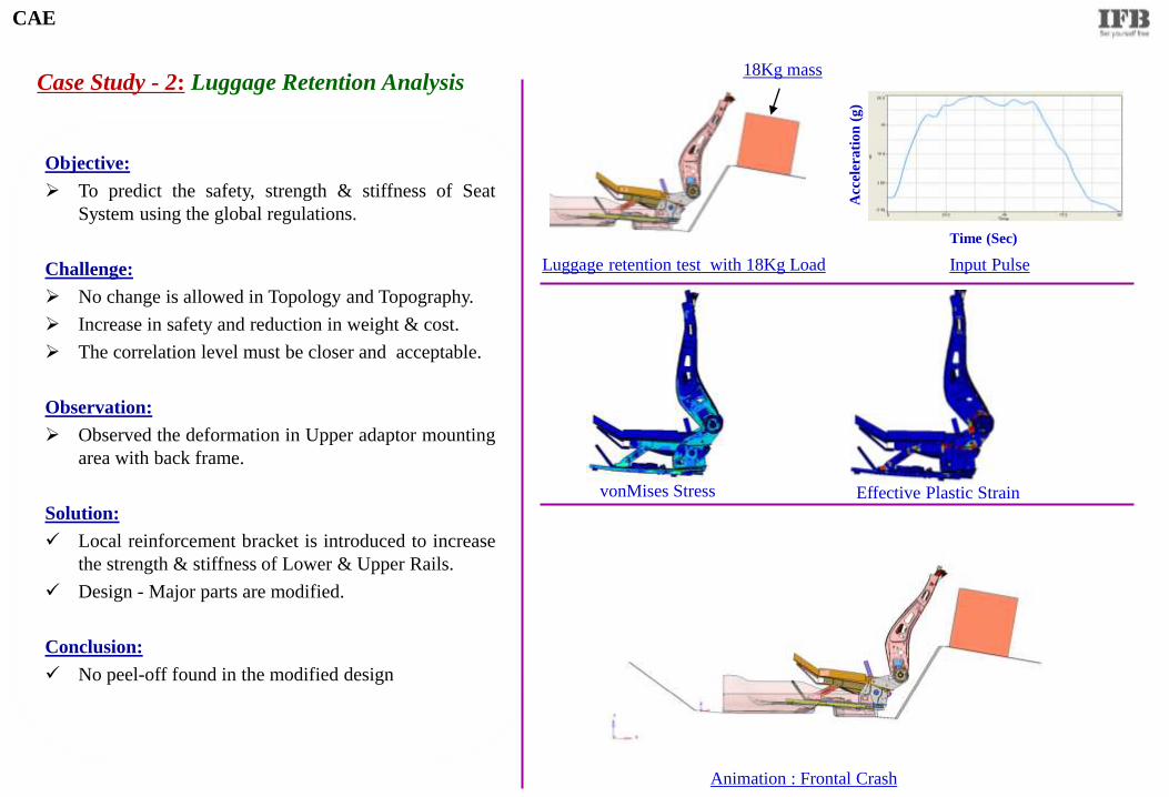
Objective:
To predict the safety, strength & stiffness of Seat
System using the global regulations.
Challenge:
No change is allowed in Topology and Topography.
Increase in safety and reduction in weight & cost.
The correlation level must be closer and acceptable.
Observation:
Observed the deformation in Upper adaptor mounting
area with back frame.
Solution:
Local reinforcement bracket is introduced to increase
the strength & stiffness of Lower & Upper Rails.
Design - Major parts are modified.
Conclusion:
No peel-off found in the modified design
Case Study - 2: Luggage Retention Analysis
Luggage retention test with 18Kg Load Input Pulse
vonMises Stress Effective Plastic Strain
Animation : Frontal Crash
Acc
eler
ati
on
(g
)
Time (Sec)
CAE
18Kg mass
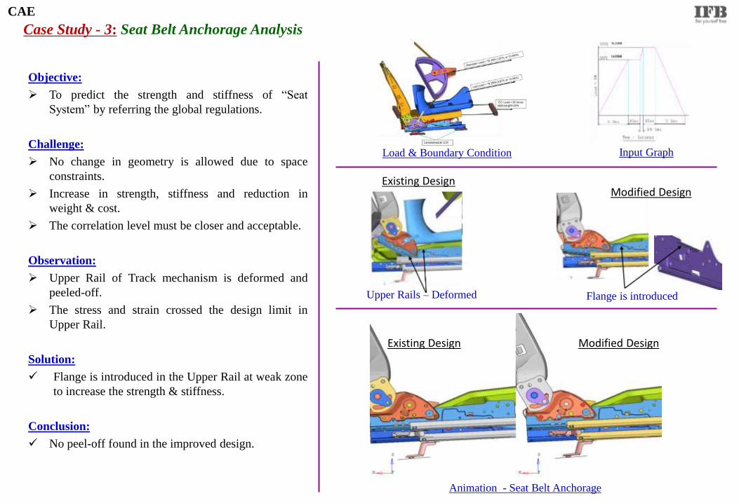
Objective:
To predict the strength and stiffness of “Seat
System” by referring the global regulations.
Challenge:
No change in geometry is allowed due to space
constraints.
Increase in strength, stiffness and reduction in
weight & cost.
The correlation level must be closer and acceptable.
Observation:
Upper Rail of Track mechanism is deformed and
peeled-off.
The stress and strain crossed the design limit in
Upper Rail.
Solution:
Flange is introduced in the Upper Rail at weak zone
to increase the strength & stiffness.
Conclusion:
No peel-off found in the improved design.
Case Study - 3: Seat Belt Anchorage Analysis
Load & Boundary Condition Input Graph
Upper Rails – Deformed Flange is introduced
Animation - Seat Belt Anchorage
Existing Design Modified Design
Existing Design Modified Design
CAE
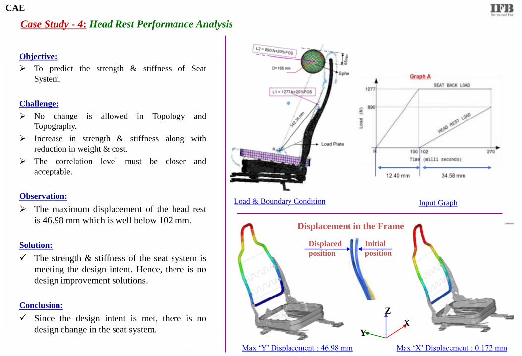
Objective:
To predict the strength & stiffness of Seat
System.
Challenge:
No change is allowed in Topology and
Topography.
Increase in strength & stiffness along with
reduction in weight & cost.
The correlation level must be closer and
acceptable.
Observation:
The maximum displacement of the head rest
is 46.98 mm which is well below 102 mm.
Solution:
The strength & stiffness of the seat system is
meeting the design intent. Hence, there is no
design improvement solutions.
Conclusion:
Since the design intent is met, there is no
design change in the seat system.
Case Study - 4: Head Rest Performance Analysis
CAE
Max ‘Y’ Displacement : 46.98 mm Max ‘X’ Displacement : 0.172 mm
Initial
position
Displaced
position
Displacement in the Frame
X
Z
Y
Load & Boundary Condition Input Graph
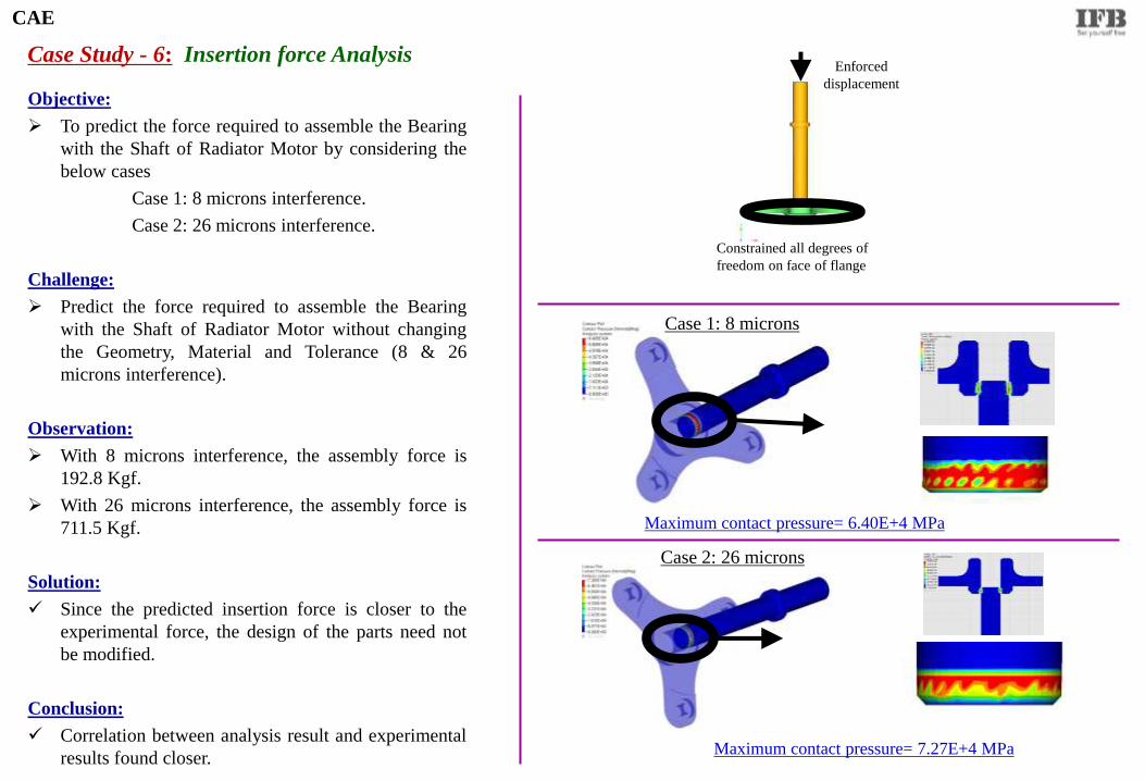
Case Study - 6: Insertion force Analysis
Objective:
To predict the force required to assemble the Bearing
with the Shaft of Radiator Motor by considering the
below cases
Case 1: 8 microns interference.
Case 2: 26 microns interference.
Challenge:
Predict the force required to assemble the Bearing
with the Shaft of Radiator Motor without changing
the Geometry, Material and Tolerance (8 & 26
microns interference).
Observation:
With 8 microns interference, the assembly force is
192.8 Kgf.
With 26 microns interference, the assembly force is
711.5 Kgf.
Solution:
Since the predicted insertion force is closer to the
experimental force, the design of the parts need not
be modified.
Conclusion:
Correlation between analysis result and experimental
results found closer.
Constrained all degrees of
freedom on face of flange
Enforced
displacement
Maximum contact pressure= 6.40E+4 MPa
Case 1: 8 microns
Maximum contact pressure= 7.27E+4 MPa
Case 2: 26 microns
CAE

Case Study - 7: Sequential Drop Analysis
Front Load Washing Machine Input Parameters
Drop Animation
Objective:
To predict the strength & stiffness of the major parts
of the Washing Machine.
Challenge:
No change is allowed in Topology and Topography.
Malfunction of WM is not allowed.
Correlation level must be closer and acceptable.
Observation:
Cabinet: Deformation found more in Corner Drops
compared with Edge Drops.
The stress and strain level is beyond the design limit
at Transportation Bolt.
Solution:
The emboss in Cabinet is modified to increase the
strength and stiffness.
Design and properties of thermocol is optimized.
Conclusion:
The damage level is within the design intent.
Correlation Level : Virtual Result found closer to the Physical test
Transportation Bolt Area Thermocol (EPS Foam)
Vertical Drops
Edge Drops
Corner Drops
CAE
1. Velocity
2. Acceleration
3. Drop Height
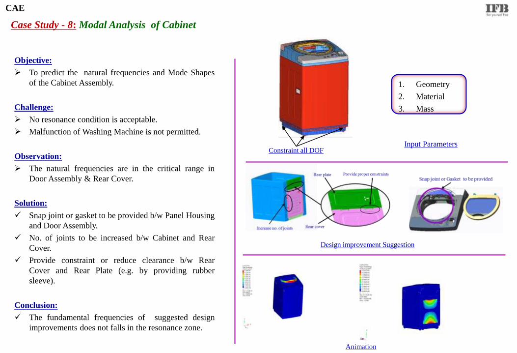
Case Study - 8: Modal Analysis of Cabinet
Objective:
To predict the natural frequencies and Mode Shapes
of the Cabinet Assembly.
Challenge:
No resonance condition is acceptable.
Malfunction of Washing Machine is not permitted.
Observation:
The natural frequencies are in the critical range in
Door Assembly & Rear Cover.
Solution:
Snap joint or gasket to be provided b/w Panel Housing
and Door Assembly.
No. of joints to be increased b/w Cabinet and Rear
Cover.
Provide constraint or reduce clearance b/w Rear
Cover and Rear Plate (e.g. by providing rubber
sleeve).
Conclusion:
The fundamental frequencies of suggested design
improvements does not falls in the resonance zone.
CAE
Design improvement Suggestion
Constraint all DOF
1. Geometry
2. Material
3. Mass
Animation
Input Parameters
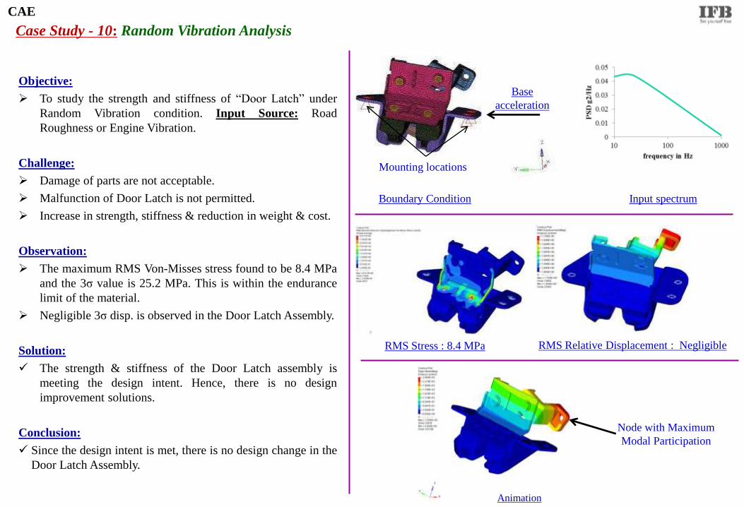
Case Study - 10: Random Vibration Analysis
Objective:
To study the strength and stiffness of “Door Latch” under
Random Vibration condition. Input Source: Road
Roughness or Engine Vibration.
Challenge:
Damage of parts are not acceptable.
Malfunction of Door Latch is not permitted.
Increase in strength, stiffness & reduction in weight & cost.
Observation:
The maximum RMS Von-Misses stress found to be 8.4 MPa
and the 3σ value is 25.2 MPa. This is within the endurance
limit of the material.
Negligible 3σ disp. is observed in the Door Latch Assembly.
Solution:
The strength & stiffness of the Door Latch assembly is
meeting the design intent. Hence, there is no design
improvement solutions.
Conclusion:
Since the design intent is met, there is no design change in the
Door Latch Assembly.
CAE
Animation
Base
acceleration
Mounting locations
Input spectrum Boundary Condition
Node with Maximum
Modal Participation
RMS Stress : 8.4 MPa RMS Relative Displacement : Negligible
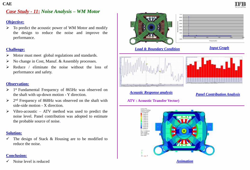
Case Study - 11: Noise Analysis – WM Motor
Load & Boundary Condition Input Graph
Animation
Objective:
To predict the acoustic power of WM Motor and modify
the design to reduce the noise and improve the
performance.
Challenge:
Motor must meet global regulations and standards.
No change in Cost, Manuf. & Assembly processes.
Reduce / eliminate the noise without the loss of
performance and safety.
Observation:
1st Fundamental Frequency of 865Hz was observed on
the shaft with up-down motion - Y direction.
2nd Frequency of 868Hz was observed on the shaft with
side-side motion - X direction.
Vibro-acoustic – ATV method was used to predict the
noise level. Panel contribution was adopted to estimate
the probable source of noise.
Solution:
The design of Stack & Housing are to be modified to
reduce the noise.
Conclusion:
Noise level is reduced
Acoustic Response analysis Panel Contribution Analysis
ATV : Acoustic Transfer Vector)
CAE
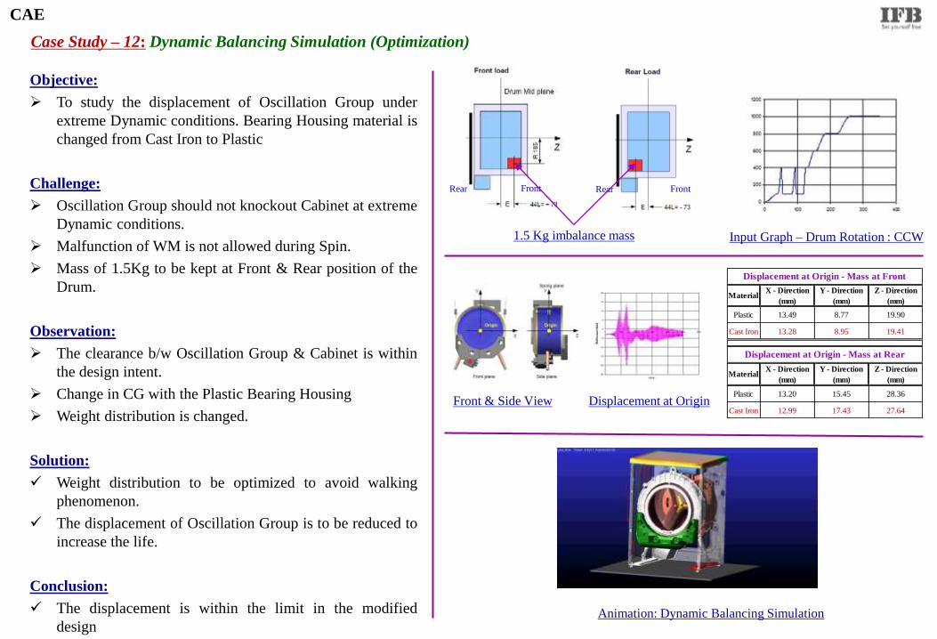
Case Study – 12: Dynamic Balancing Simulation (Optimization)
Input Graph – Drum Rotation : CCW
Objective:
To study the displacement of Oscillation Group under
extreme Dynamic conditions. Bearing Housing material is
changed from Cast Iron to Plastic
Challenge:
Oscillation Group should not knockout Cabinet at extreme
Dynamic conditions.
Malfunction of WM is not allowed during Spin.
Mass of 1.5Kg to be kept at Front & Rear position of the
Drum.
Observation:
The clearance b/w Oscillation Group & Cabinet is within
the design intent.
Change in CG with the Plastic Bearing Housing
Weight distribution is changed.
Solution:
Weight distribution to be optimized to avoid walking
phenomenon.
The displacement of Oscillation Group is to be reduced to
increase the life.
Conclusion:
The displacement is within the limit in the modified
design
CAE
Animation: Dynamic Balancing Simulation
1.5 Kg imbalance mass
Front Rear Front Rear
Displacement at Origin Front & Side View
MaterialX - Direction
(mm)
Y - Direction
(mm)
Z - Direction
(mm)
Plastic 13.49 8.77 19.90
Cast Iron 13.28 8.95 19.41
MaterialX - Direction
(mm)
Y - Direction
(mm)
Z - Direction
(mm)
Plastic 13.20 15.45 28.36
Cast Iron 12.99 17.43 27.64
Displacement at Origin - Mass at Front
Displacement at Origin - Mass at Rear
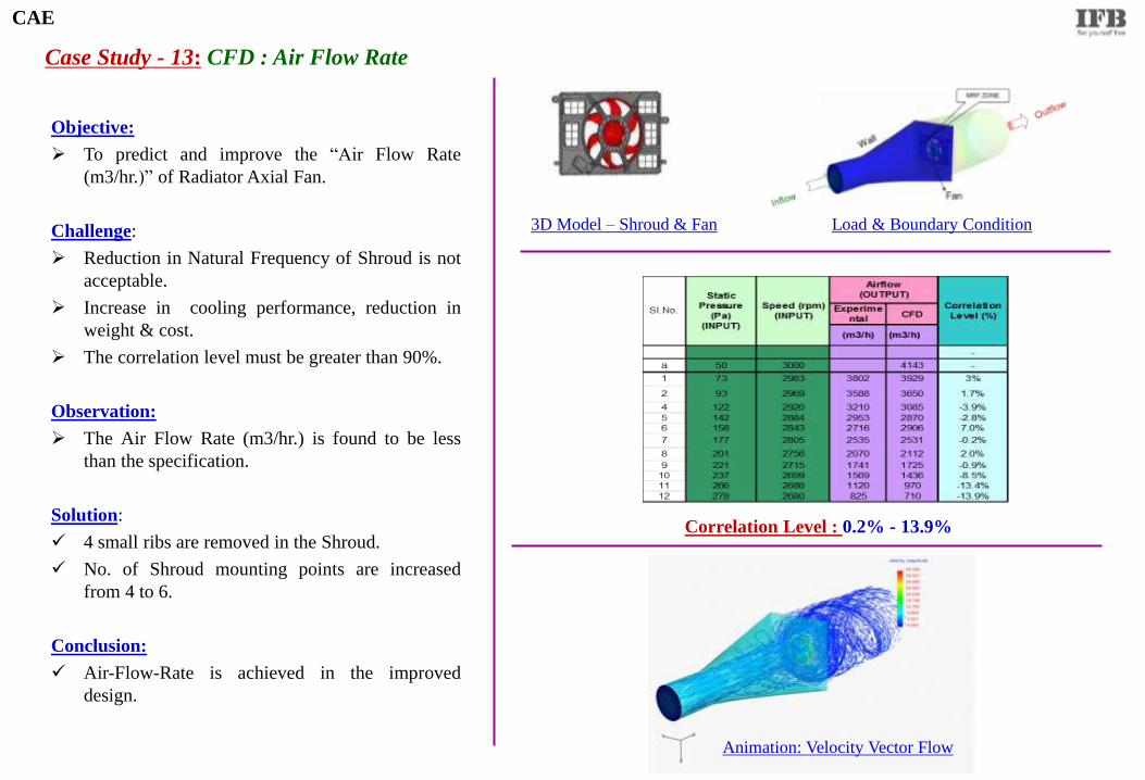
Objective:
To predict and improve the “Air Flow Rate
(m3/hr.)” of Radiator Axial Fan.
Challenge:
Reduction in Natural Frequency of Shroud is not
acceptable.
Increase in cooling performance, reduction in
weight & cost.
The correlation level must be greater than 90%.
Observation:
The Air Flow Rate (m3/hr.) is found to be less
than the specification.
Solution:
4 small ribs are removed in the Shroud.
No. of Shroud mounting points are increased
from 4 to 6.
Conclusion:
Air-Flow-Rate is achieved in the improved
design.
Case Study - 13: CFD : Air Flow Rate
Load & Boundary Condition
Correlation Level : 0.2% - 13.9%
Animation: Velocity Vector Flow
CAE
3D Model – Shroud & Fan
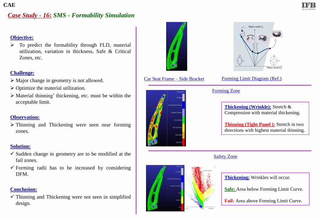
Case Study - 16: SMS - Formability Simulation
Forming Limit Diagram (Ref.)
Objective:
To predict the formability through FLD, material
utilization, variation in thickness, Safe & Critical
Zones, etc.
Challenge:
Major change in geometry is not allowed.
Optimize the material utilization.
Material thinning’ thickening, etc. must be within the
acceptable limit.
Observation:
Thinning and Thickening were seen near forming
zones.
Solution:
Sudden change in geometry are to be modified at the
fail zones.
Forming radii has to be increased by considering
DFM.
Conclusion:
Thinning and Thickening were not seen in simplified
design.
Car Seat Frame – Side Bracket
CAE
Forming Zone
Safety Zone
Thickening (Wrinkle): Stretch &
Compression with material thickening.
Thinning (Tight Panel ): Stretch in two
directions with highest material thinning.
Thickening: Wrinkles will occur.
Safe: Area below Forming Limit Curve.
Fail: Area above Forming Limit Curve.
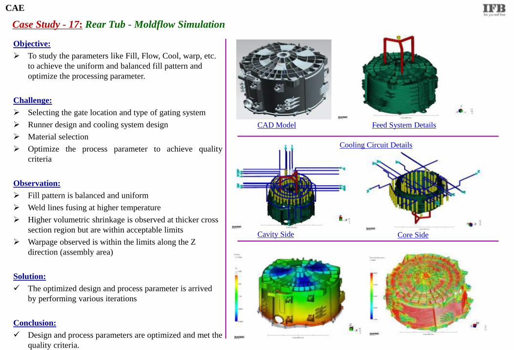
Case Study - 17: Rear Tub - Moldflow Simulation
Feed System Details CAD Model
CAE
Cooling Circuit Details
Cavity Side Core Side
Objective:
To study the parameters like Fill, Flow, Cool, warp, etc.
to achieve the uniform and balanced fill pattern and
optimize the processing parameter.
Challenge:
Selecting the gate location and type of gating system
Runner design and cooling system design
Material selection
Optimize the process parameter to achieve quality
criteria
Observation:
Fill pattern is balanced and uniform
Weld lines fusing at higher temperature
Higher volumetric shrinkage is observed at thicker cross
section region but are within acceptable limits
Warpage observed is within the limits along the Z
direction (assembly area)
Solution:
The optimized design and process parameter is arrived
by performing various iterations
Conclusion:
Design and process parameters are optimized and met the
quality criteria.
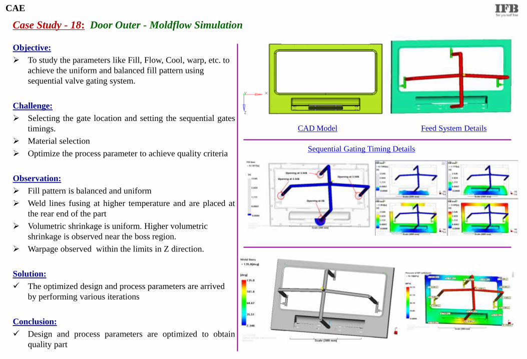
Case Study - 18: Door Outer - Moldflow Simulation
Feed System Details
Objective:
To study the parameters like Fill, Flow, Cool, warp, etc. to
achieve the uniform and balanced fill pattern using
sequential valve gating system.
Challenge:
Selecting the gate location and setting the sequential gates
timings.
Material selection
Optimize the process parameter to achieve quality criteria
Observation:
Fill pattern is balanced and uniform
Weld lines fusing at higher temperature and are placed at
the rear end of the part
Volumetric shrinkage is uniform. Higher volumetric
shrinkage is observed near the boss region.
Warpage observed within the limits in Z direction.
Solution:
The optimized design and process parameters are arrived
by performing various iterations
Conclusion:
Design and process parameters are optimized to obtain
quality part
CAD Model
CAE
Sequential Gating Timing Details
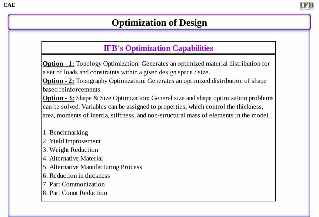
Optimization of Design
CAE
IFB's Optimization Capabilities
Option - 1: Topology Optimization: Generates an optimized material distribution for
a set of loads and constraints within a given design space / size.
Option - 2: Topography Optimization: Generates an optimized distribution of shape
based reinforcements.
Option - 3: Shape & Size Optimization: General size and shape optimization problems
can be solved. Variables can be assigned to properties, which control the thickness,
area, moments of inertia, stiffness, and non-structural mass of elements in the model.
1. Benchmarking
2. Yield Improvement
3. Weight Reduction
4. Alternative Material
5. Alternative Manufacturing Process
6. Reduction in thickness
7. Part Commonization
8. Part Count Reduction
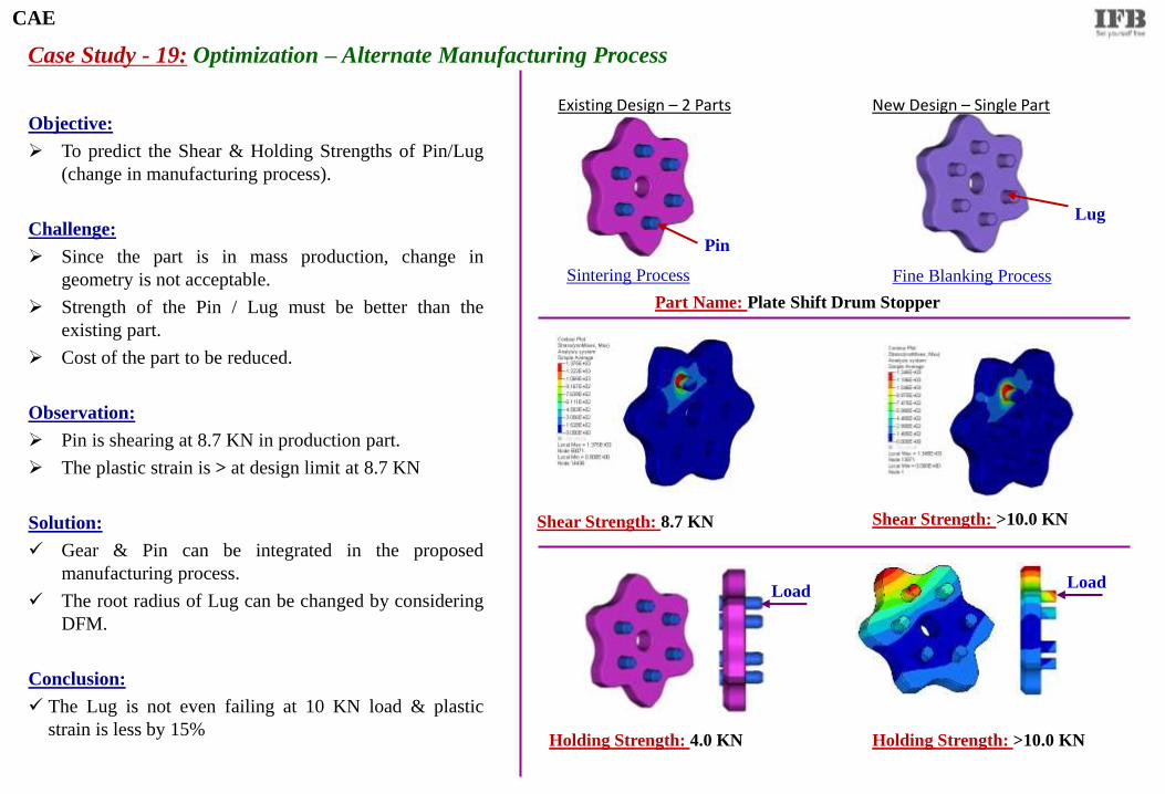
Case Study - 19: Optimization – Alternate Manufacturing Process
Sintering Process Fine Blanking Process
Shear Strength: 8.7 KN
Existing Design – 2 Parts New Design – Single Part Objective:
To predict the Shear & Holding Strengths of Pin/Lug
(change in manufacturing process).
Challenge:
Since the part is in mass production, change in
geometry is not acceptable.
Strength of the Pin / Lug must be better than the
existing part.
Cost of the part to be reduced.
Observation:
Pin is shearing at 8.7 KN in production part.
The plastic strain is > at design limit at 8.7 KN
Solution:
Gear & Pin can be integrated in the proposed
manufacturing process.
The root radius of Lug can be changed by considering
DFM.
Conclusion:
The Lug is not even failing at 10 KN load & plastic
strain is less by 15%
Part Name: Plate Shift Drum Stopper
Lug
Pin
Shear Strength: >10.0 KN
Load
Holding Strength: >10.0 KN
Load
Holding Strength: 4.0 KN
CAE
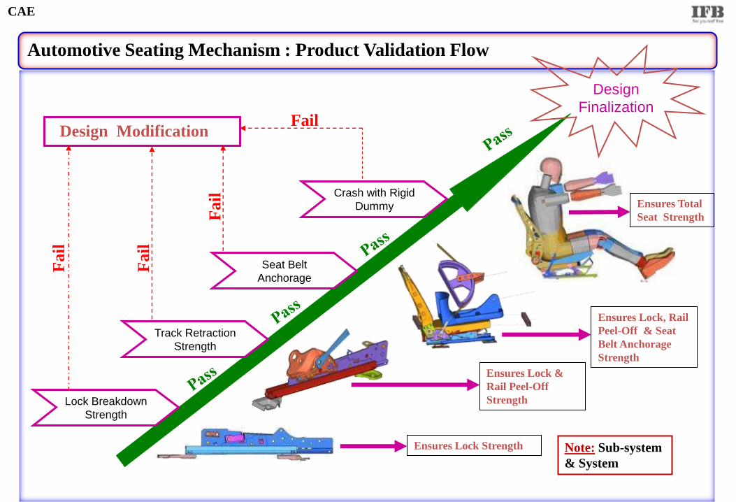
Automotive Seating Mechanism : Product Validation Flow
Lock Breakdown
Strength
Track Retraction
Strength
Seat Belt
Anchorage
Crash with Rigid
Dummy
Ensures Lock Strength
Ensures Lock &
Rail Peel-Off
Strength
Ensures Lock, Rail
Peel-Off & Seat
Belt Anchorage
Strength
Ensures Total
Seat Strength
Design
Finalization
Design Modification
Fail
Fail
Fa
il
Fail
Note: Sub-system
& System
CAE

Side Clamping Test
Vertical Bounce Test
Horizontal
Bounce Test
Bevel Hitting Test
No damage, part separation,
breakage, etc. are acceptable
No malfunction of
WM is acceptable
after completing
the test
Design Modification
Fa
il
Fail
Fail
Fail
Sequential Drop Test (9)
Fail
Note: Washing Machine must be in
fully packed condition No damage
is acceptable
No damage, part separation,
breakage, etc. are acceptable
No damage, part separation,
breakage, etc. are acceptable
Implicit
Explicit
Final
Design
CAE
Home Appliance : Transportation Test : Product Validation Flow
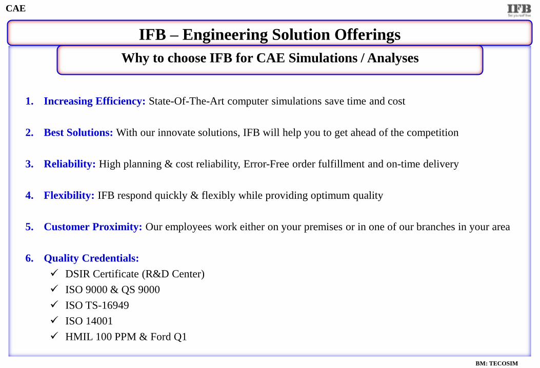
Why to choose IFB for CAE Simulations / Analyses
IFB – Engineering Solution Offerings
CAE
1. Increasing Efficiency: State-Of-The-Art computer simulations save time and cost
2. Best Solutions: With our innovate solutions, IFB will help you to get ahead of the competition
3. Reliability: High planning & cost reliability, Error-Free order fulfillment and on-time delivery
4. Flexibility: IFB respond quickly & flexibly while providing optimum quality
5. Customer Proximity: Our employees work either on your premises or in one of our branches in your area
6. Quality Credentials:
DSIR Certificate (R&D Center)
ISO 9000 & QS 9000
ISO TS-16949
ISO 14001
HMIL 100 PPM & Ford Q1
BM: TECOSIM
IFB Automotive Private Limited #16, Visveswariah Industrial Estate,
1st Main Road, Off Whitefield Road, Mahadevapura,
Bangalore, Karnataka, India - 560 048
Tel (Board) : 91 80 39884450
Fax : 91 80 39842778
Contact : Mr. M.RAMALINGAM
Head – CAE Division
Phone (Dir) : 91 80 39842376
Mobile : 91 80 9343769920
E-mail : [email protected]
CAE


![CAE Characterization and Optimization of Automotive Seat ... · The detailed method of CAE modeling or concept modeling is extensively discussed in the literature [15]. Altair Hyper](https://static.documents.pub/doc/80x56/5e47cd60ca3f6a6ab87c0f83/cae-characterization-and-optimization-of-automotive-seat-the-detailed-method.jpg)

