42
SIGALARM MODEL 210 iFLEX E5/1 Load Moment Indicator OPERATOR’S MANUAL

SIGALARM MODEL 210
iFLEX E5/1 Load Moment Indicator
OPERATOR’S MANUAL


Operator’s Manual
SkyAzúl, Equipment Solutions www.skyazul.com 301-371-6126
NOTICE
SkyAzúl makes no warranty of any kind with regard to this material, including, but not limited to, the implied warranties of merchantability and/or its fitness for a particular purpose.
SkyAzúl will not be liable for errors contained in this manual or for incidental or consequential damages in connection with the furnishing, performance, or use of this manual. This document contains proprietary information, which is protected by copyright, and all rights are reserved.
No part of this document may be photocopied, reproduced, or translated to another language without the prior written consent of SkyAzúl.
SkyAzúl reserves proprietary rights to all drawings, photos and the data contained therein. The drawings, photos and data are confidential and cannot be used or reproduced without the written consent of Hirschmann. The drawings and/or photos are subject to technical modification without prior notice.
All information in this document is subject to change without notice.
MANUAL REVISIONS
REV DATE NAME DESCRIPTION
- 08/09/13 SC iFLEX E5/1 Operator’s Manual (SkyAzúl) For XCMG QUY220/QUY250/QUY260/QUY280/QUY300
SkyAzúl, Inc. 16 Walnut Street Middletown, MD 21769 Fax 301-371-0029 [email protected]

iFLEX E5/1 – Load Moment Indicator
SkyAzúl, Equipment Solutions www.skyazul.com 301-371-6126
1
Table of content
1. GENERAL INFORMATION ........................................................................................ 2
2. IMPORTANT NOTES ................................................................................................. 3
3.SYSTEM CONFIGURATION ......................................................................................... 4
3.1 IFLEXE5/1 CONTROLLER ..................................................................................................... 5 3.2 IFLEX C CONTROLLER(OPTIONAL) ........................................................................................ 6 3.3 IK2001 CONSOLE .................................................................................................................. 7 3.4 FORCE SENSOR ................................................................................................................... 8
3.4.1 Technical Data ............................................................................................................ 8 3.4.2 Installation .................................................................................................................. 8
3.5 WG SERIES ANGLE SENSOR ................................................................................................... 9 3.5.1 Technical datas .......................................................................................................... 9 3.5.2 Installation .................................................................................................................. 9
3.6 DAVS PRESSURE TRANSDUCER(OPTIONAL) ...................................................................... 10 3.6.1 Technical data .......................................................................................................... 10 3.6.2 Installation ................................................................................................................ 10
3.7 ANTI-TWO BLOCK SWITCH ................................................................................................... 11 3.7.1 Technical data .......................................................................................................... 11 3.7.2 Installation ................................................................................................................ 11
3.8 WIND TRANSMMITTER(OPTIONAL) ........................................................... 4.DISPLAY AND INTERFACE ........................................................................................ 13
4.1 STATUS DISPLAY .................................................................................................................. 14 4.2 IMAGE AREA (VALUES ARE NOT REAL) ................................................................................... 15 4.3 FUNCTION KEY SYMBOLS ....................................................................................................... 17 4.3 FUNCTION KEYS ................................................................................................................... 17
5.OPERATING METHOD (VALUES ARE NOT REAL) .................................................. 18
5.1 OM AND REEVING SETUP ..................................................................................................... 19 5.1.1 OM code information ............................................................................................... 20 5.1.2 Numerical OM code setup ....................................................................................... 20 5.1.3 Geometrical OM setup ............................................................................................. 21 5.1.4 Reeving setup .......................................................................................................... 21
5.2 SYSTEM INFORMATION .......................................................................................................... 22 5.2.1 Signal overviwe ........................................................................................................ 22 5.2.2 Load chart information ............................................................................................ 24 5.2.3 Error code information ............................................................................................ 25 5.2.4 CAN bus status overview ........................................................................................ 25
5.3 DISPLAY SETUP .................................................................................................................... 26 5.3.1 Time setting .............................................................................................................. 26 5.3.2 Brightness adjusting ............................................................................................... 27 5.3.3 Metric unit / Imperial unit selection ........................................................................ 27 5.3.4 Chinese/English language selection ...................................................................... 27
6 INSPECTION MAINTENANCE AND CONSIDERATIONS ............................................. 28
6.1 INSPECTION BEFORE OPERATION .......................................................................................... 28 6.2 ROUTINE MAINTENANCE ....................................................................................................... 28 6.3 ROUTINE CONSIDERATION ..................................................................................................... 28 6.4 BUZZER ALARMS .................................................................................................................. 28 6.5 ANGLE SENSOR ADJUSTMENT ............................................................................................... 28
7. TROUBLE SHOOTING ................................................................................................. 29
Operator's Manual iFLEX E5/1 - Load Moment Indicator
SkyAzúl, Equipment Solutions www.skyazul.com 301-371-6126

2
1. General Information
The Hirschmann load moment indicator (herein refer to LMI) iFLEX E5/1 and control
system are designed for all types of mobile cranes.
The iFLEX E5/1 can provide the crane operator with important information necessary
for the operation of the crane within the areas of operation specified by the manufacturer.
The LMI uses a variety of different sensors to monitor different crane functions and
communicates the crane performance data to the crane operator on a continuous basis.
This data changes constantly in connection with the crane movements.
The LMI provides the operator with the information of the length and angle of the boom,
tip height, working radius, rated load and the actual load weight and so on.
If the crane nears its safe load limit, the system will warn the crane operator by means
of both acoustic and optical signals. In addition, as soon as the crane reaches an
unauthorized operating status, all crane movements will be switched off that would increase
the load moment on the crane.
This manual only introduced the operating method of the LMI. Details of the crane
operating standards please refer to the crane operating manual provided by the crane
manufacturers.
This manual is for XMGC QUY220/QUY250/QUY260/QUY280/QUY300 crawler crane.
Please read it carefully before starting the operation and take the actual crane console
display as standard.
Operator's Manual iFLEX E5/1 - Load Moment Indicator
SkyAzúl, Equipment Solutions www.skyazul.com 301-371-6126
3
2. Important Notes
The LMI control system is an assistant collocation for safe operation that warns a machine
operator of approaching overload conditions and of over-hoist conditions that could cause
damage to equipment and personnel.
The device is not, and shall not, be a substitute for good operator judgment, experience
and use of accepted safe machine operating procedures.
Safe operation is the responsibility for every machine operator. Every machine operator must ensure that they read all warnings and instructions carefully and fully understand. Correct operation depends on daily careful checking and serious study of the Manual.
The LMI is not able to provide aid to the machine operator unless it has been properly adjusted and unless the correct load capacity chart and the correct operating code have been entered for the respective rigging configuration. The correctness of the SLI settings must be guaranteed before beginning machine work in order to avoid damage to property and severe or even fatal injuries to personnel
If you SLM in use fails or is not functioning properly, please do stop the operation of the crane, and contact expert service engineer. SkyAul does not assume any responsibility for undesirable consequences resulted from this continued action!
Operator's Manual iFLEX E5/1 - Load Moment Indicator
SkyAzúl, Equipment Solutions www.skyazul.com 301-371-6126
4
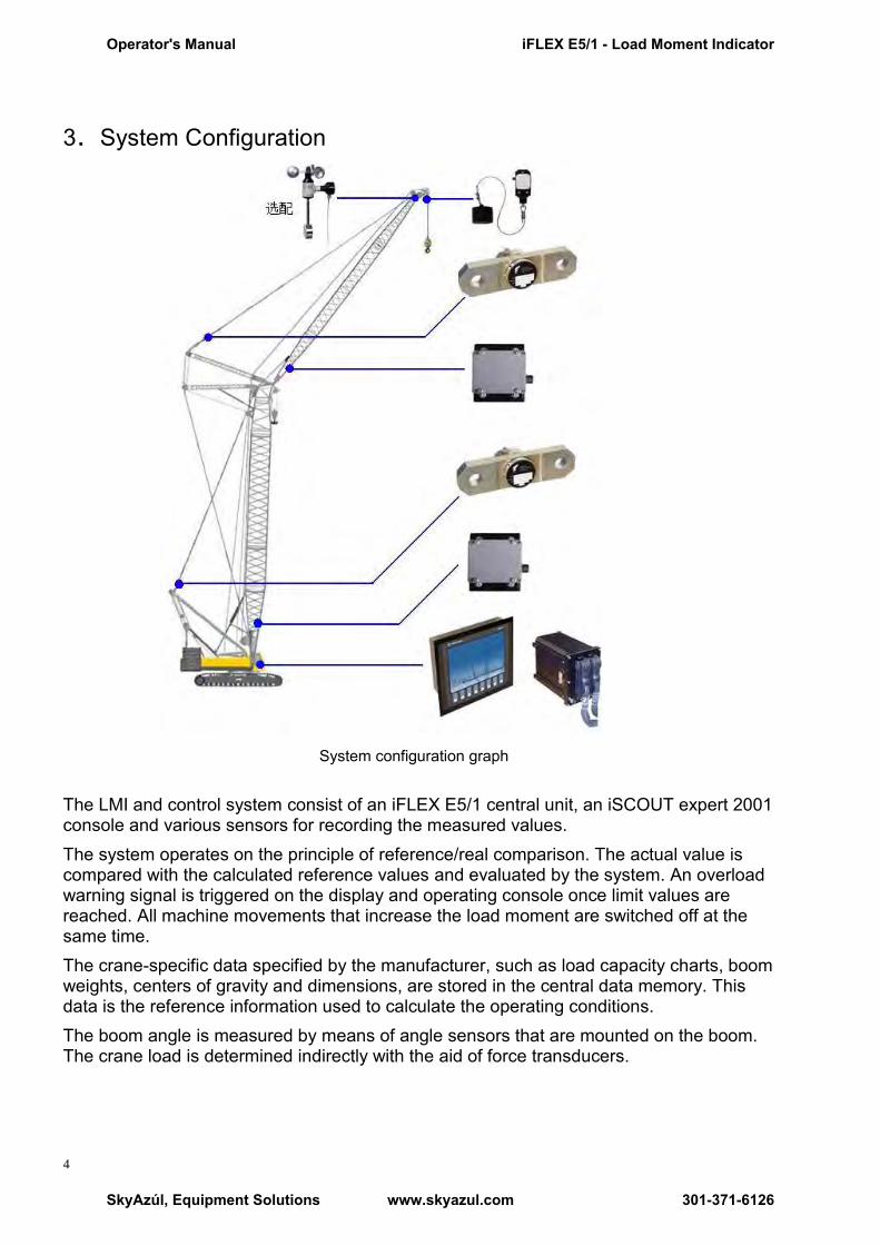
3.System Configuration
System configuration graph The LMI and control system consist of an iFLEX E5/1 central unit, an iSCOUT expert 2001 console and various sensors for recording the measured values. The system operates on the principle of reference/real comparison. The actual value is compared with the calculated reference values and evaluated by the system. An overload warning signal is triggered on the display and operating console once limit values are reached. All machine movements that increase the load moment are switched off at the same time. The crane-specific data specified by the manufacturer, such as load capacity charts, boom weights, centers of gravity and dimensions, are stored in the central data memory. This data is the reference information used to calculate the operating conditions. The boom angle is measured by means of angle sensors that are mounted on the boom. The crane load is determined indirectly with the aid of force transducers.
Operator's Manual iFLEX E5/1 - Load Moment Indicator
SkyAzúl, Equipment Solutions www.skyazul.com 301-371-6126

5
3.1 iFLEXE5/1 Controller
iFLEXE5/1 Controller:32 digit industrial control PLC system and high-powered processor qualify the requirements of harsh environment for all kinds of industrial system. iFLEX5/1 module is composed of base board and extended board. Customers could choose different iFLEX5/1 module according to their own needs. Each module can be connected by CANBUS. Due to the building block mode, the iFLEX5/1 is not only applicable to medium and small control systems, but also to big and complicated control systems.
iFLEX E5/1 controller dimension graph
iFLEX E5/1 controller installation graph
Technical datas: CPU: 32BitRISC-processor 48MHz Memory:8MB Flash(can upload to16MB) Protection class:IP67 Field Bus: 1×CANopen2.0B ; 1×SAE J1939 Connection: 2×RS232, 1×RS485 Operating voltage:10V~30VDC Operating temperature:-30℃~+70℃ Storing temperature:-40℃~+85℃
Operator's Manual iFLEX E5/1 - Load Moment Indicator
SkyAzúl, Equipment Solutions www.skyazul.com 301-371-6126

6
3.2 iFLEX C Controller(optional)
iFLEX C (compact class) product series are programmable and flexible
configuration of the inputs and outputs. The CANopen interface allows the set up of a
decentralized network which offer minimal installation and servicing costs.
iFLEX C3 controller dimension graph
Technical data: CPU: 16Bit or 32Bit Protection class:IP65 Bus: 1×CANopen+1×RS485 Interface: 1×RS232 Operating voltage:10V~36VDC Anolog input:4~20 mA,0~5V Operating temperature: -20℃~+70℃ Storing temperature: -30℃~+80℃
Operator's Manual iFLEX E5/1 - Load Moment Indicator
SkyAzúl, Equipment Solutions www.skyazul.com 301-371-6126

7
3.3 IK2001 console
IK2001 console –BestVIEW adaptive display can show all the operational data that you concerned. The combination between the Graphical display and Genersys software achieve the on-line program for graph. The strong graph compiled capability is incomparable with other Industrial displays.
IK2001console dimension graph
Technical datas: type: in-dash/ on-dash housing: metal protection class:front panel IP65,back panel IP65/IP20 Operating voltage:10V~36VDC Operating temperature:-20℃~+70℃ Storing temperatiure:-35℃~+80℃ Display: resolution VGA(640×480) Dimention10.4Zoll(diagonal), color 256colors Dimention: front panel(W×H)293×265.9 Section panel dimention:(W×H×D)270×232×64 Connection: 2×CANopen2.0B/1×Ethernet, RS232+RS485, MMC/SD Slot
Operator's Manual iFLEX E5/1 - Load Moment Indicator
SkyAzúl, Equipment Solutions www.skyazul.com 301-371-6126
8
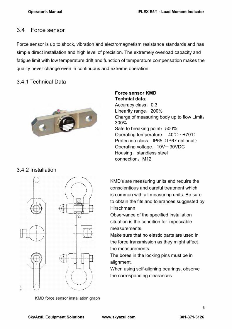
3.4 Force sensor
Force sensor is up to shock, vibration and electromagnetism resistance standards and has
simple direct installation and high level of precision. The extremely overload capacity and
fatigue limit with low temperature drift and function of temperature compensation makes the
quality never change even in continuous and extreme operation.
3.4.1 Technical Data
Force sensor KMD Technial data: Accuracy class:0.3 Linearity range:200% Charge of measuring body up to flow Limit:300% Safe to breaking point:500% Operating temperature:-40℃~+70℃ Protection class:IP65(IP67 optional) Operating voltage:10V~30VDC Housing:standless steel connection:M12
3.4.2 Installation
KMD's are measuring units and require the conscientious and careful treatment which is common with all measuring units. Be sure to obtain the fits and tolerances suggested by Hirschmann Observance of the specified installation situation is the condition for impeccable measurements. Make sure that no elastic parts are used in the force transmission as they might affect the measurements. The bores in the locking pins must be in alignment. When using self-aligning bearings, observe the corresponding clearances
KMD force sensor installation graph
Operator's Manual iFLEX E5/1 - Load Moment Indicator
SkyAzúl, Equipment Solutions www.skyazul.com 301-371-6126

9
3.5 WG series Angle Sensor
WG absolute value angle sensor is simple direct installation and compact and can precisely measure the angle of boom. The sealed housing keeps the inside component away from infection of temperature, humidity ,etc.
3.5.1 Technical datas
WG angle sensor installation dimension graph
Measuring range:WG103_0-90°WG104_0-270° Operating voltage:9-33VDC Output signal:current 4-20mA Linearity tolerance:<±0.2° Hysteresis tolerance:<±0.1° Operating temperature:-40℃~+85℃ Storing temperature:-40℃~+85℃ Protection class:IP67
3.5.2 Installation
When install an angle sensor, the position shall be well considered. Generally along the he foot points of boom to the top direction, the angle sensor is installed inside the right boom foot (left location); on the contrary it is the right location. With no particular explanation, all the angle sensors should be installed on the left location. When install an angle sensor, the boom shall be put on an horizontal supporter and make sure horizontal center of the sensor and the boom are in parallel. After the installation, do remember to exam the reliability and security.
Installation graph
Horizontal center
line of the boom
Angle sensor
Foot point of
the boom
Operator's Manual iFLEX E5/1 - Load Moment Indicator
SkyAzúl, Equipment Solutions www.skyazul.com 301-371-6126

10
3.6 DAVS pressure transducer(optional)
DAVS pressure transducers measure high static and dynamic pressure values of liquids or gases in rough operating environment. Measuring precision is maintained even during continuous operation at extremely dynamic pressure. The pressure transducer come with a pressure connector with standardized G1/4 thread.
3.6.1 Technical data
Operating voltage: 8~32VDC
Output signal:current 4-20mA CANopen(optional)
Operating temperature: -40℃~+85℃
Storing temperature: -40℃~+100℃
Protection class: IP67
Life expectancy: 〉10million cycles Hysteresis tolerance: 〈±0.1%FS max.
DAVS dimension graph
3.6.2 Installation
Please notice the location of hydraulic piping and valve when install the pressure transducer. By thread connection (such as follow graph), screw the pressure transducer in the hydraulic piping or seat of the balancing valves or hydraulic valves. Add the appropriate seal to the interface to prevent oil leakage. Guarantee the installation position is safe, considerable and easy for cable connecting. Make sure the pressure sensor and hydraulic adaptor connect tightly. The tightening moment of G1/4 connector is 20Nm
connector pin assignment
Operator's Manual iFLEX E5/1 - Load Moment Indicator
SkyAzúl, Equipment Solutions www.skyazul.com 301-371-6126

11
3.7 Anti-Two Block Switch
Anti-Two Block Switch is positive opening limit switch for winches,lifting devices and cranes and is simple direct installation and compact. The sealed housing keeps the inside component away from infection of temperature, humidity ,etc.
3.7.1 Technical data
Operating voltage: 15~30V
Operating temperature: -25℃~+70℃
Storing temperature: -40℃~ +70℃
Protection class: IP67
Life expectancy: >5×10⁶次
housing: aluminium Weight: 1.2kg A2B高度限位开关外形尺寸
3.7.2 Installation
The switch should be installed in the side of boom header which the beginning of the lifting rope is fixed. Make sure the hammer is stuck in the beginning of the lifting rope and connect the hammer with the switch by the specific rope. The signal connector and cable must be waterproof and connected correctly.
Ati-Two block switch
Operator's Manual iFLEX E5/1 - Load Moment Indicator
SkyAzúl, Equipment Solutions www.skyazul.com 301-371-6126
12
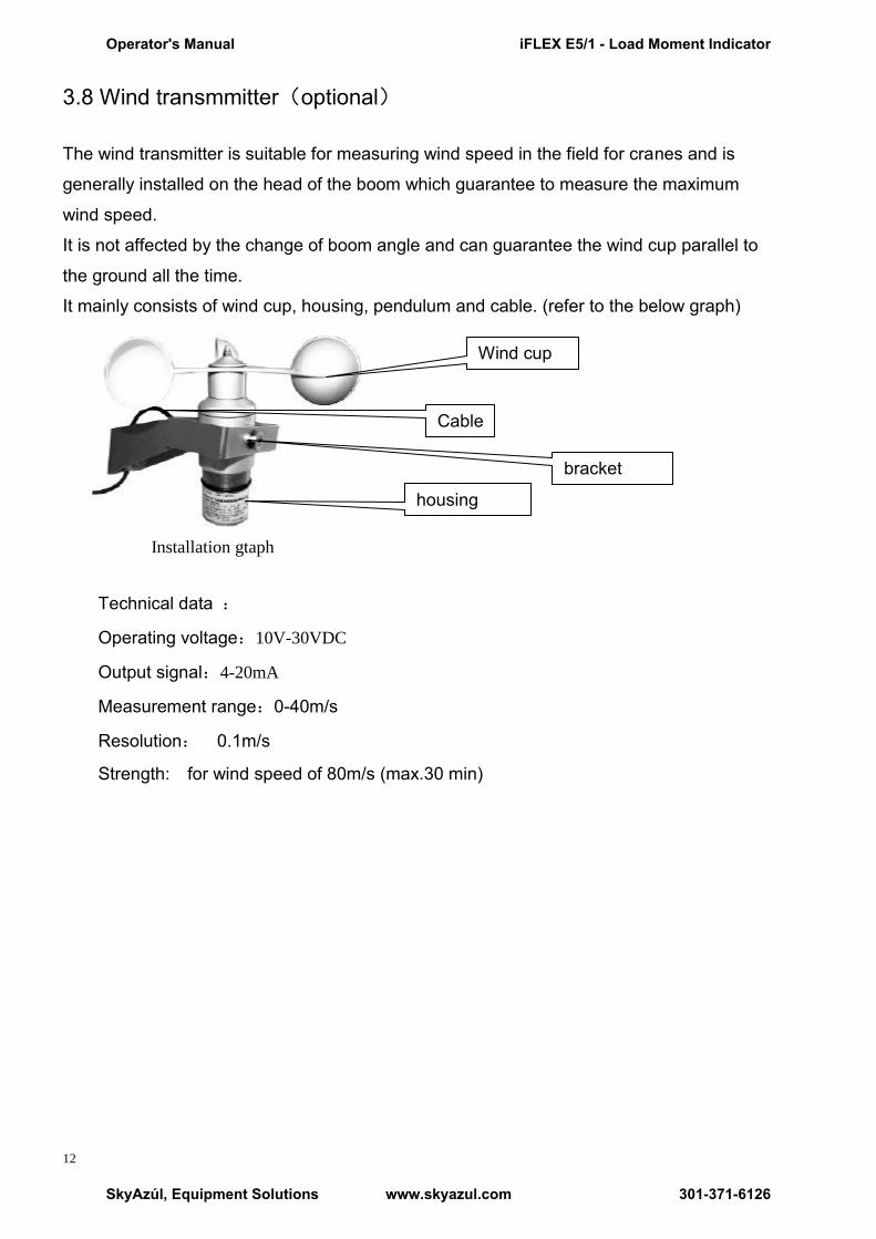
3.8 Wind transmmitter(optional)
The wind transmitter is suitable for measuring wind speed in the field for cranes and is
generally installed on the head of the boom which guarantee to measure the maximum
wind speed.
It is not affected by the change of boom angle and can guarantee the wind cup parallel to
the ground all the time.
It mainly consists of wind cup, housing, pendulum and cable. (refer to the below graph)
Installation gtaph
Technical data :
Operating voltage:10V-30VDC
Output signal:4-20mA
Measurement range:0-40m/s
Resolution: 0.1m/s
Strength: for wind speed of 80m/s (max.30 min)
Wind cup
housing
Cable
bracket
Operator's Manual iFLEX E5/1 - Load Moment Indicator
SkyAzúl, Equipment Solutions www.skyazul.com 301-371-6126
13
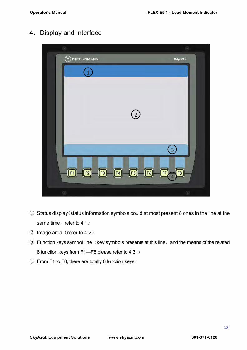
4.Display and interface
① Status display(status information symbols could at most present 8 ones in the line at the
same time,refer to 4.1)
② Image area(refer to 4.2)
③ Function keys symbol line(key symbols presents at this line,and the means of the related
8 function keys from F1—F8 please refer to 4.3 )
④ From F1 to F8, there are totally 8 function keys.
1
v
v
v
v
2
v
v
v
v
3
v
v
v
v 4
v
v
v
v
Operator's Manual iFLEX E5/1 - Load Moment Indicator
SkyAzúl, Equipment Solutions www.skyazul.com 301-371-6126

14
4.1 Status display
A.error code symbol
Operators can find out the failure cause according to the error code
B.Reeving symbol
Current reeving
C.OM code symbol
Current OM code.
D. CANBUS symbol
CAN communication between the console and controller is error.
E.A2B switch warning symbol
This red symboll lights up when the contacts of the lifting limit switch open, i.e. a lifting limit has been reached. The audio alarm sounds and any load moment-increasing crane movements are immediately switched off.
F.Loadmoment Pre-warning symbol
This yellow symboll lights up when the crane load exceeds 90 % of the respective reference safe working load and an overload situation is imminent.
G.Overload symbol
This red symbol lights up when the crane load has reached 100% of the maximum safe working load for the current operating situation and indicates to the crane operator that an overload situation has occurred. The audio alarm is sounded. Any load moment-increasing crane movements are immediately switched off.
H.time symbol
Display local time
The crane operator can learn the crane operating status from the status symbols
which appear on top of the console. Before the operation, operators shall fully
understand the meaning of the follow symbols and make correct judgment accordingly.
Notice
Operator's Manual iFLEX E5/1 - Load Moment Indicator
SkyAzúl, Equipment Solutions www.skyazul.com 301-371-6126
15
4.2 Image area (values are not real)
IK2001 console VGA (640×480)can display all the operational data. The Bestview
patent technology can help to provide clear and visual graphic display either under blazing
sun or in dark night.
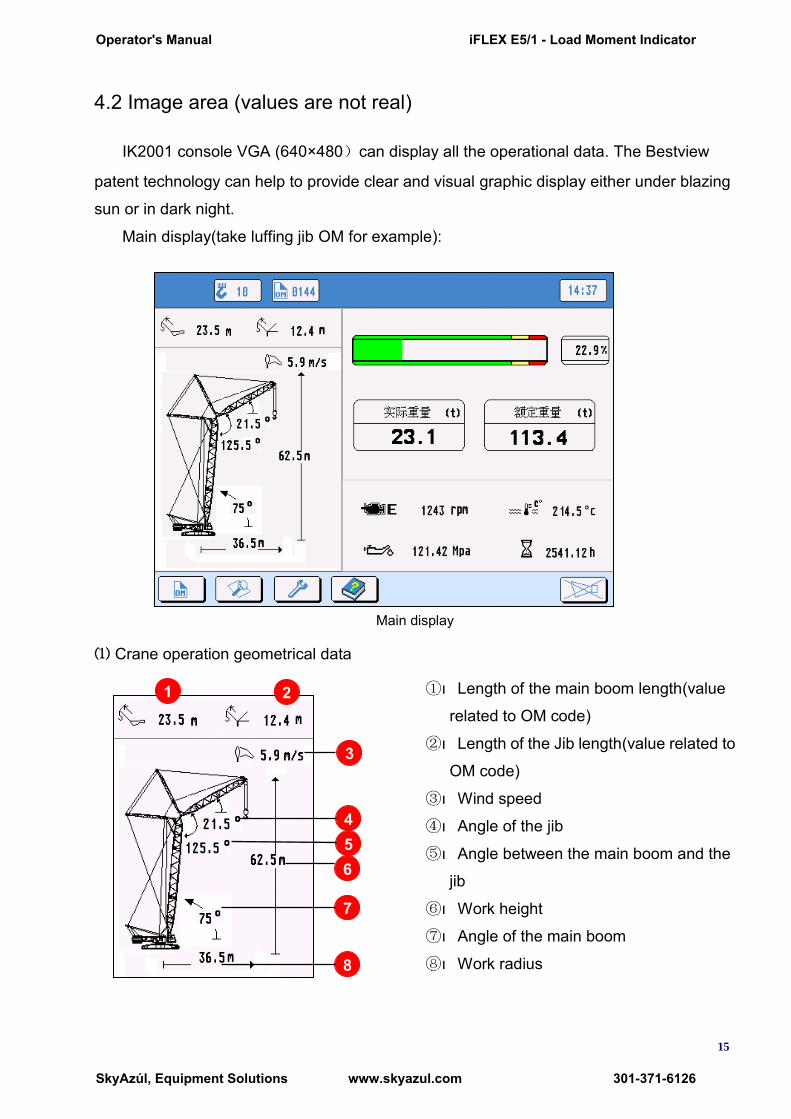
Main display(take luffing jib OM for example):
Main display
⑴ Crane operation geometrical data
①ı Length of the main boom length(value
related to OM code)
②ı Length of the Jib length(value related to
OM code)
③ı Wind speed
④ı Angle of the jib
⑤ı Angle between the main boom and the
jib
⑥ı Work height
⑦ı Angle of the main boom
⑧ı Work radius
1 2
3
4 5 6
7
8
Operator's Manual iFLEX E5/1 - Load Moment Indicator
SkyAzúl, Equipment Solutions www.skyazul.com 301-371-6126
16
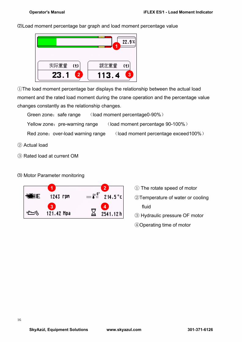
⑵Load moment percentage bar graph and load moment percentage value
①The load moment percentage bar displays the relationship between the actual load
moment and the rated load moment during the crane operation and the percentage value
changes constantly as the relationship changes.
Green zone:safe range (load moment percentage0-90%)
Yellow zone:pre-warning range (load moment percentage 90-100%)
Red zone:over-load warning range (load moment percentage exceed100%)
② Actual load
③ Rated load at current OM
⑶ Motor Parameter monitoring
① The rotate speed of motor
②Temperature of water or cooling
fluid
③ Hydraulic pressure OF motor
④Operating time of motor
1
3 2
1 2
3 4
Operator's Manual iFLEX E5/1 - Load Moment Indicator
SkyAzúl, Equipment Solutions www.skyazul.com 301-371-6126

17
4.3 Function key symbols
There are totally 8 function keys symbols in the keys symbol line(no display means not available). Different interface may present different key symbols. Operators need to operate the LMI by the related function keys. Introduce the meanings of the key symbols in the main display as below:
F1:OM and reeving setup key symbol
F2:System checking key symbol
F3:System setup key symbol
F4:Help key symbol
F8:‖Alarm off‖ key symbol
The acoustic alarm can be suppressed temporarily by pressing this function key.
4.4 Function keys
There are totally 8 function keys from F1toF8. Each of the keys is corresponding with the function key symbol.
Operator's Manual iFLEX E5/1 - Load Moment Indicator
SkyAzúl, Equipment Solutions www.skyazul.com 301-371-6126
18
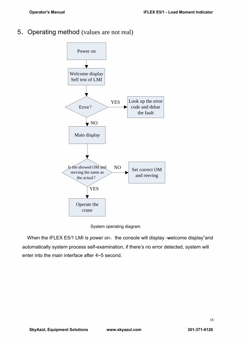
5.Operating method (values are not real)
System operating diagram
When the iFLEX E5/1 LMI is power on,the console will display ―welcome display‖and
automatically system process self-examination, if there’s no error detected, system will
enter into the main interface after 4~5 second.
Power on
Welcome display
Self test of LMI
Error?Look up the error
code and debar
the fault
YES
NO
Is the showed OM and
reeving the same as
the actual?
NO
Main display
Set correct OM
and reeving
YES
Operate the
crane
Operator's Manual iFLEX E5/1 - Load Moment Indicator
SkyAzúl, Equipment Solutions www.skyazul.com 301-371-6126
19
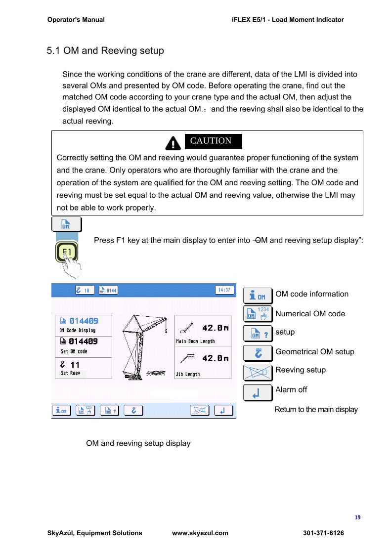
5.1 OM and Reeving setup
Since the working conditions of the crane are different, data of the LMI is divided into several OMs and presented by OM code. Before operating the crane, find out the matched OM code according to your crane type and the actual OM, then adjust the displayed OM identical to the actual OM.;and the reeving shall also be identical to the actual reeving.
Press F1 key at the main display to enter into ―OM and reeving setup display‖:
OM code information
Numerical OM code
setup
Geometrical OM setup
Reeving setup
Alarm off
Return to the main display
OM and reeving setup display
Correctly setting the OM and reeving would guarantee proper functioning of the system and the crane. Only operators who are thoroughly familiar with the crane and the operation of the system are qualified for the OM and reeving setting. The OM code and reeving must be set equal to the actual OM and reeving value, otherwise the LMI may not be able to work properly.
CAUTION
Operator's Manual iFLEX E5/1 - Load Moment Indicator
SkyAzúl, Equipment Solutions www.skyazul.com 301-371-6126
20
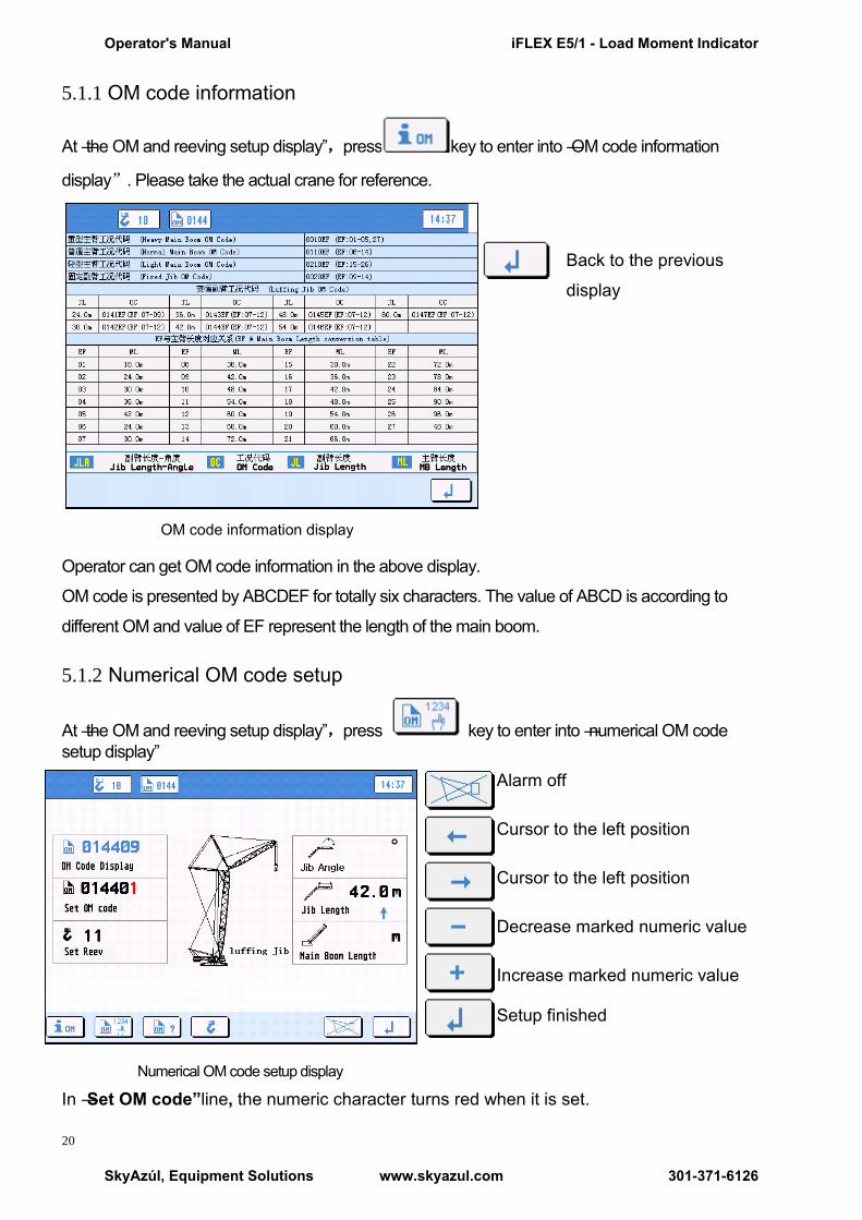
5.1.1 OM code information
At ―the OM and reeving setup display‖,press key to enter into ―OM code information
display”. Please take the actual crane for reference.
Back to the previous
display
OM code information display
Operator can get OM code information in the above display.
OM code is presented by ABCDEF for totally six characters. The value of ABCD is according to
different OM and value of EF represent the length of the main boom.
5.1.2 Numerical OM code setup
At ―the OM and reeving setup display‖,press key to enter into ―numerical OM code setup display‖
Alarm off
Cursor to the left position
Cursor to the left position
Decrease marked numeric value
Increase marked numeric value
Setup finished
Numerical OM code setup display
In ―Set OM code”line, the numeric character turns red when it is set.
Operator's Manual iFLEX E5/1 - Load Moment Indicator
SkyAzúl, Equipment Solutions www.skyazul.com 301-371-6126

21
After setup, press key to enter into ―select saving or not key line‖:
Saving the setup (The OM code display line will change into the new set OM code)
Cancel the setup(The OM code display line will remain )
5.1.3 Geometrical OM setup
At ―the OM and reeving setup display‖,press key to enter into ―Geometrical OM setup‖:
Select previous value
Select next value
Back to the previous setting
Alarm off
Jump to the next setting (only select correct value in the present setting)
Geometrical OM setup
There are four setting in the ―Geometrical OM setup‖- OM type setting, main boom length
setting, jib length setting and jib angle setting.
Firstly select OM type, then select jib angle (only in fixed jib OM available) and jib length
(only in luffing jib and fixed jib OM available) and lastly select main boom length.
After setup, press key to enter into ―select saving or not key line‖:
Saving the setup (The OM code display line will change into the new set OM code)
Cancel the setup(The OM code display line will remain )
5.1.4 Reeving setup
At ―the OM and reeving setup display‖,press to enter into reeving setup display:
In ―Set Reev” line, the numeric character turns red when it is set. And please refer the
setup method to ―numerical OM code setup‖ chapter.
Operator's Manual iFLEX E5/1 - Load Moment Indicator
SkyAzúl, Equipment Solutions www.skyazul.com 301-371-6126
22
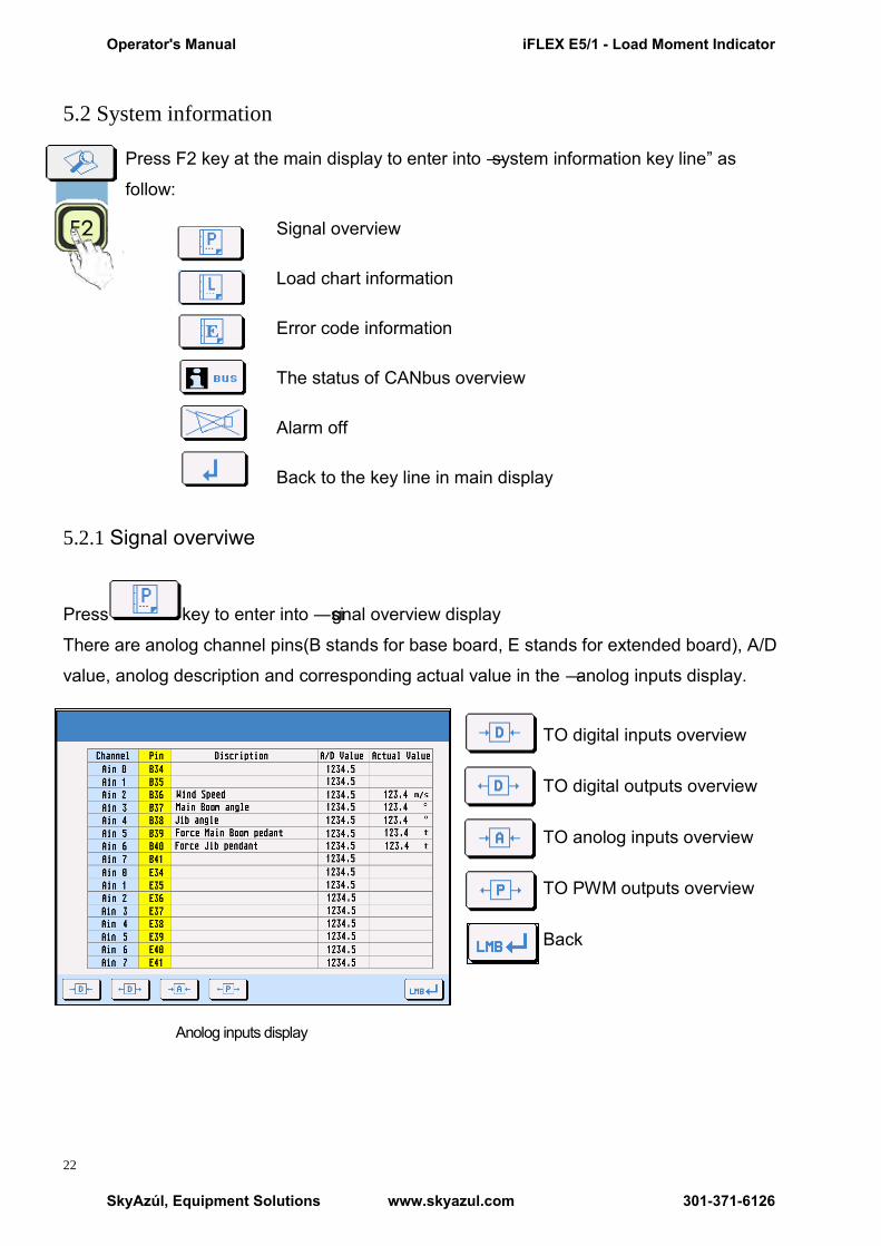
5.2 System information
Press F2 key at the main display to enter into ―system information key line‖ as
follow:
Signal overview
Load chart information
Error code information
The status of CANbus overview
Alarm off
Back to the key line in main display
5.2.1 Signal overviwe
Press key to enter into ―signal overview display
There are anolog channel pins(B stands for base board, E stands for extended board), A/D
value, anolog description and corresponding actual value in the ― anolog inputs display.
TO digital inputs overview TO digital outputs overview TO anolog inputs overview TO PWM outputs overview Back
Anolog inputs display
Operator's Manual iFLEX E5/1 - Load Moment Indicator
SkyAzúl, Equipment Solutions www.skyazul.com 301-371-6126
23
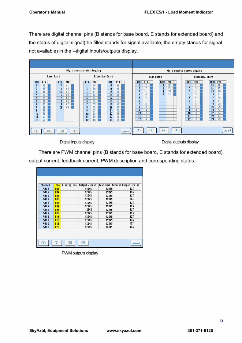
There are digital channel pins (B stands for base board, E stands for extended board) and
the status of digital signal(the filled stands for signal available, the empty stands for signal
not available) in the ― digital inputs/outputs display.
Digital inputs display Digital outputs display
There are PWM channel pins (B stands for base board, E stands for extended board),
output current, feedback current, PWM description and corresponding status.
PWM outputs display
Operator's Manual iFLEX E5/1 - Load Moment Indicator
SkyAzúl, Equipment Solutions www.skyazul.com 301-371-6126
24
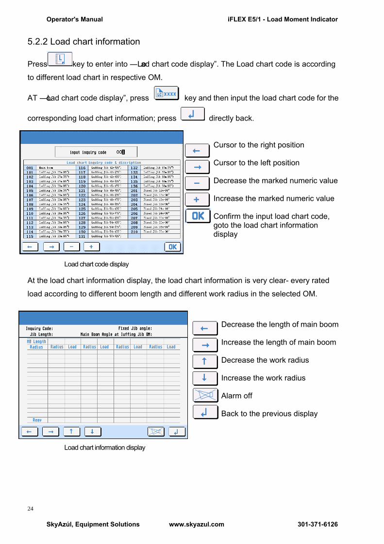
5.2.2 Load chart information
Press key to enter into ―Load chart code display‖. The Load chart code is according
to different load chart in respective OM.
AT ―Load chart code display‖, press key and then input the load chart code for the
corresponding load chart information; press directly back.
Cursor to the right position
Cursor to the left position
Decrease the marked numeric value
Increase the marked numeric value
Confirm the input load chart code, goto the load chart information display
Load chart code display
At the load chart information display, the load chart information is very clear- every rated
load according to different boom length and different work radius in the selected OM.
Decrease the length of main boom
Increase the length of main boom
Decrease the work radius
Increase the work radius
Alarm off
Back to the previous display
Load chart information display
Operator's Manual iFLEX E5/1 - Load Moment Indicator
SkyAzúl, Equipment Solutions www.skyazul.com 301-371-6126
25
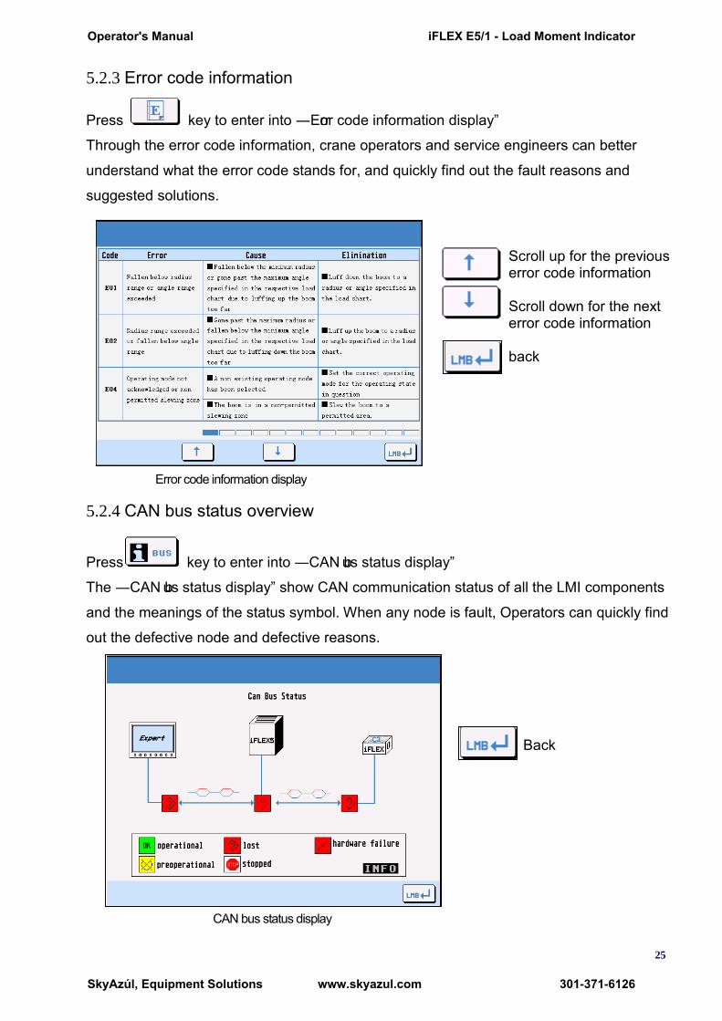
5.2.3 Error code information
Press key to enter into ―Error code information display‖
Through the error code information, crane operators and service engineers can better
understand what the error code stands for, and quickly find out the fault reasons and
suggested solutions.
Scroll up for the previous error code information Scroll down for the next error code information back
Error code information display
5.2.4 CAN bus status overview
Press key to enter into ―CAN bus status display‖
The ―CAN bus status display‖ show CAN communication status of all the LMI components
and the meanings of the status symbol. When any node is fault, Operators can quickly find
out the defective node and defective reasons.
Back
CAN bus status display
Operator's Manual iFLEX E5/1 - Load Moment Indicator
SkyAzúl, Equipment Solutions www.skyazul.com 301-371-6126

26
5.3 Display setup
Press F3 key at the main display to enter into ―display setup key line‖ as follow:
Time setting
Brightness adjusting
Metric unit / Imperial unit selection
Chinese/English version selection
Alarm off
Back
5.3.1 Time setting
Press key to enter into ―Time setting display‖
Cursor to the right position
Cursor to the left position
Decrease the marked numeric value
Increase the marked numeric value
Confirm the time setting and back
Time setting display
Operator's Manual iFLEX E5/1 - Load Moment Indicator
SkyAzúl, Equipment Solutions www.skyazul.com 301-371-6126

27
5.3.2 Brightness adjusting
Press key to enter into ―Brightness adjusting display‖
daytime mode- brightness directly to 100% night mode brightness directly to 65% Brightness progressively increase ―5%‖ Brightness progressively decrease ―5%‖ Confirm the brightness adjusting and back
Brightness adjusting display
5.3.3 Metric unit / Imperial unit selection
Press key to select Metric unit or imperial unit
In the metric display, the unit of length is ―m‖ and the unit of weight is ―t‖. In the imperial
display, the unit of length is ―ft‖ and the unit of weight is ―klbs‖.
Metric and Imperial conversion relationship: 1 m = 3.2808 feet; 1 kg = 2.20462 pounds.
5.3.4 Chinese/English language selection
Press key to select Chinese language or English language.
Operator's Manual iFLEX E5/1 - Load Moment Indicator
SkyAzúl, Equipment Solutions www.skyazul.com 301-371-6126

28
6 Inspection maintenance and considerations
6.1 Inspection before operation
Check all components of the LMI system to make sure no one is damaged or break off. Turn the power on and detect that if the display is normal and if there is warning,
malfunction, error indication and so on. After display works normally, detect that if all the system works normally.
6.2 Routine maintenance
Check the angle transducer .as to oil leakage. Check the cable reel as to sufficient tight or not. Check the insulating layer of all the cables. If the insulating layer or the wire inside
damaged, please replace new one immediately. Clean the display termly to make it clear.
6.3 Routine consideration
Prevent the central unit (display)、power supply cabin、sensors from severely shake. Each part of the LMI system including central unit (display), sensors and so on had been
regulated critically and ingress protection checked before leaving factory. Anyone not be trained professionally is prohibited from dismantling the housing. Otherwise, the system will probably not work normally because of humidity and dust getting into the components.
6.4 Buzzer alarms
If the system shows normal without any fault codes after started, but the buzzer alarms. At the moment, exam whether the conjunction between cable and A2B is junction off or short circuit of water-in.
6.5 Angle sensor adjustment
Use the angle instrument to measure if the displayed value is the same when the actual angle is between 0°and 70°. If the displayed value or radius is not the same with the actual value, operators should adjust the angle sensor. Release the adjusting bolt (see the left pic.),Slowly turn the angle sensor till the displayed value accords with the actual value and then tighten the bolt again.
Operator's Manual iFLEX E5/1 - Load Moment Indicator
SkyAzúl, Equipment Solutions www.skyazul.com 301-371-6126
29
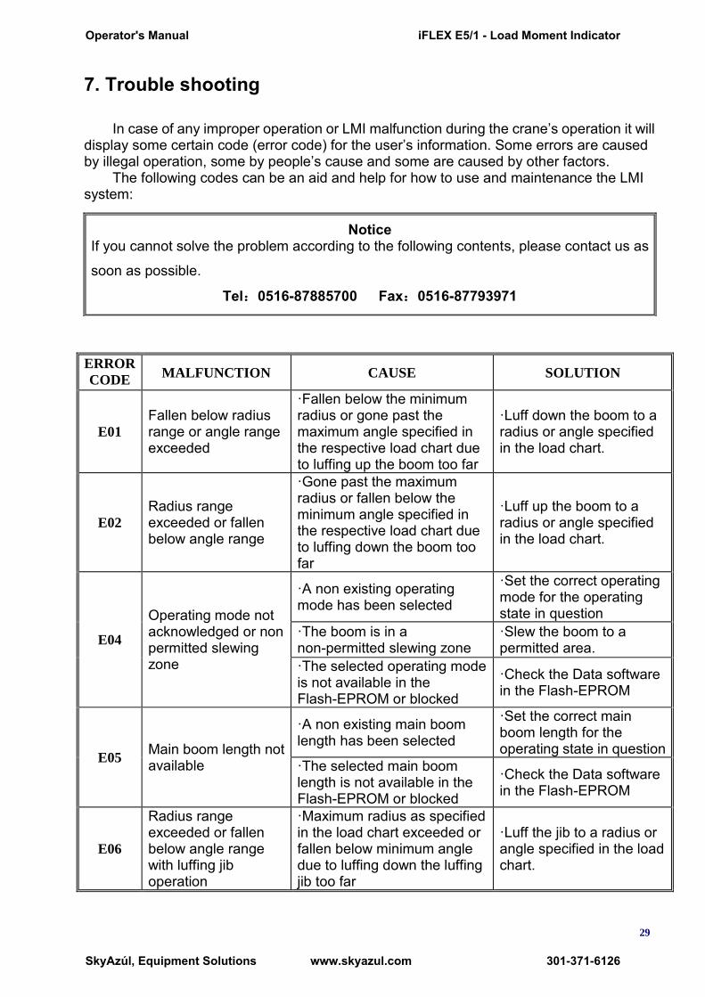
7. Trouble shooting
In case of any improper operation or LMI malfunction during the crane’s operation it will display some certain code (error code) for the user’s information. Some errors are caused by illegal operation, some by people’s cause and some are caused by other factors.
The following codes can be an aid and help for how to use and maintenance the LMI system:
ERROR
CODE MALFUNCTION CAUSE SOLUTION
E01
Fallen below radius range or angle range exceeded
·Fallen below the minimum radius or gone past the maximum angle specified in the respective load chart due to luffing up the boom too far
·Luff down the boom to a radius or angle specified in the load chart.
E02
Radius range exceeded or fallen below angle range
·Gone past the maximum radius or fallen below the minimum angle specified in the respective load chart due to luffing down the boom too far
·Luff up the boom to a radius or angle specified in the load chart.
E04
Operating mode not acknowledged or non permitted slewing zone
·A non existing operating mode has been selected
·Set the correct operating mode for the operating state in question
·The boom is in a non-permitted slewing zone
·Slew the boom to a permitted area.
·The selected operating mode is not available in the Flash-EPROM or blocked
·Check the Data software in the Flash-EPROM
E05 Main boom length not available
·A non existing main boom length has been selected
·Set the correct main boom length for the operating state in question
·The selected main boom length is not available in the Flash-EPROM or blocked
·Check the Data software in the Flash-EPROM
E06
Radius range exceeded or fallen below angle range with luffing jib operation
·Maximum radius as specified in the load chart exceeded or fallen below minimum angle due to luffing down the luffing jib too far
·Luff the jib to a radius or angle specified in the load chart.
Notice If you cannot solve the problem according to the following contents, please contact us as
soon as possible.
Tel:0516-87885700 Fax:0516-87793971
Operator's Manual iFLEX E5/1 - Load Moment Indicator
SkyAzúl, Equipment Solutions www.skyazul.com 301-371-6126
30
ERROR
CODE MALFUNCTION CAUSE SOLUTION
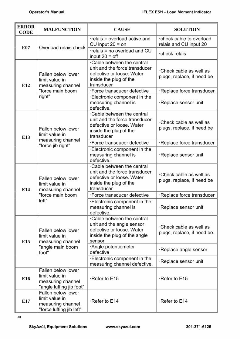
E07 Overload relais check
·relais = overload active and CU input 20 = on
·check cable to overload relais and CU input 20
·relais = no overload and CU input 20 = off ·check relais
E12
Fallen below lower limit value in measuring channel "force main boom right"
·Cable between the central unit and the force transducer defective or loose. Water inside the plug of the transducer
·Check cable as well as plugs, replace, if need be
·Force transducer defective ·Replace force transducer ·Electronic component in the measuring channel is defective.
·Replace sensor unit
E13
Fallen below lower limit value in measuring channel "force jib right"
·Cable between the central unit and the force transducer defective or loose. Water inside the plug of the transducer
·Check cable as well as plugs, replace, if need be
·Force transducer defective ·Replace force transducer ·Electronic component in the measuring channel is defective.
·Replace sensor unit
E14
Fallen below lower limit value in measuring channel "force main boom left"
·Cable between the central unit and the force transducer defective or loose. Water inside the plug of the transducer
·Check cable as well as plugs, replace, if need be
·Force transducer defective ·Replace force transducer ·Electronic component in the measuring channel is defective.
·Replace sensor unit
E15
Fallen below lower limit value in measuring channel "angle main boom foot"
·Cable between the central unit and the angle sensor defective or loose. Water inside the plug of the angle sensor
·Check cable as well as plugs, replace, if need be.
·Angle potentiometer defective ·Replace angle sensor
·Electronic component in the measuring channel defective. ·Replace sensor unit
E16
Fallen below lower limit value in measuring channel "angle luffing jib foot"
·Refer to E15 ·Refer to E15
E17
Fallen below lower limit value in measuring channel "force luffing jib left"
·Refer to E14 ·Refer to E14
Operator's Manual iFLEX E5/1 - Load Moment Indicator
SkyAzúl, Equipment Solutions www.skyazul.com 301-371-6126

31
ERROR
CODE MALFUNCTION CAUSE SOLUTION
E18
Fallen below lower limit value in measuring channel "MB back stop pressure"
·Cable between the central unit and the pressure transducer defective or loose. Water inside the plug of the transducer
·Check cable as well as plugs, replace, if need be
·Force transducer defective ·Replace force transducer
·Electronic component in the measuring channel is defective.
·Replace sensor unit
E19
Fallen below lower limit value in measuring channel " jib back stop pressure "
·Cable between the central unit and the pressure transducer defective or loose. Water inside the plug of the transducer
·Check cable as well as plugs, replace, if need be
·Force transducer defective ·Replace force transducer
·Electronic component in the measuring channel is defective.
·Replace sensor unit
E1B
Fallen below lower limit value in measuring channel "angle luffing jib tip"
·Refer to E15 ·Refer to E15
E1C
Fallen below lower limit value in measuring channel "angle main boom tip"
·Cable between the central unit and the angle sensor defective or loose. Water inside the plug of the angle sensor
·Check cable as well as plugs, replace, if need be.
·Angle potentiometer defective ·Replace angle sensor
·Electronic component in the measuring channel defective.
·Replace sensor unit
E1D
Fallen below lower limit value in measuring channel "angle super lift mast"
·Cable between the central unit and the angle sensor defective or loose. Water inside the plug of the angle sensor
·Check cable as well as plugs, replace, if need be.
·Angle potentiometer defective ·Replace angle sensor
·Electronic component in the measuring channel defective.
·Replace sensor unit
E1E
Fallen below lower limit value in measuring channel "force derricking system left"
·Refer to E14 ·Refer to E14
Operator's Manual iFLEX E5/1 - Load Moment Indicator
SkyAzúl, Equipment Solutions www.skyazul.com 301-371-6126

32
ERROR
CODE MALFUNCTION CAUSE SOLUTION
E1F
Fallen below lower limit value in measuring channel "force derricking system right"
·Refer to E14 ·Refer to E14
E22
Upper limit value in measuring channel "force main boom right" has been exceeded.
·Refer to E14 ·Refer to E14
E23
Upper limit value in measuring channel "force jib right" has been exceeded.
·Refer to E15 ·Refer to E15
E24
Upper limit value in measuring channel "force main boom left" has been exceeded.
·Refer to E14 ·Refer to E14
E25
Upper limit value in measuring channel "main boom angle foot" has been exceeded.
·Refer to E15 ·Refer to E15
E26
Upper limit value in measuring channel "luffing jib angle foot" has been exceeded.
·Refer to E15 ·Refer to E15
E27
Upper limit value in measuring channel "force luffing jib left" has been exceeded.
·Refer to E14 ·Refer to E14
E28
Upper limit value in measuring channel "MB back stop pressure" has been exceeded.
·Refer to E14 ·Refer to E14
E29
Upper limit value in measuring channel" jib back stop pressure " has been exceeded.
·Refer to E15 ·Refer to E15
E2B
Upper limit value in measuring channel "jib angle tip" has been exceeded.
·Refer to E14 ·Refer to E14
E2C
Upper limit value in measuring channel "main boom angle tip" has been exceeded.
·Refer to E15 ·Refer to E15
E2D
Upper limit value in measuring channel "super lift mast angle" has been exceeded (if avail.).
·Refer to E15 ·Refer to E15
Operator's Manual iFLEX E5/1 - Load Moment Indicator
SkyAzúl, Equipment Solutions www.skyazul.com 301-371-6126

33
ERROR
CODE MALFUNCTION CAUSE SOLUTION
E2E
Upper limit value in measuring channel "force derricking system left" has been exceeded.
·Refer to E14 ·Refer to E14
E2F
Upper limit value in measuring channel" force derricking system right" has been exceeded.
·Refer to E11 ·Refer to E11
E37 Error in the logical program flow
·System program file is defective
·Upload valid system software
·Flash-EPROM defective ·Replace central unit
E38
System program and crane data file do not match.
·The system program in the LMI does not match to the programming in the crane data file
·Upload valid system program file or the valid crane data file
E39
System program and load chart file do not match
·The system program in the LMI and the programming in the load chart file do not match.
·Upload valid system program file or the valid load chart file
E3A crane data file and load chart file do not match
·Crane type in data file and load chart file is different
·C hange data file and/or load chart file
E43 Error in the write/read memory, (RAM)
·Write/read memory (RAM) or central unit defective. ·Replace central unit
E51 Error in the crane data file
·No valid data in the crane data file.
·Upload valid crane data file
·Flash-EPROM defective
E52 Error in load chart file. ·No valid data in the load chart file
·U pload valid load chart file
·Flash-EPROM defective ·Replace central unit
E56 Error in crane data file. ·No valid data in the crane data file during calibration.
·Restore or upload valid crane data file
·Flash-EPROM defective ·Replace central unit
E57 Error in serial crane data file.
·Calibration data file does not contain valid data.
·Upload calibration data file
·Flash-EPROM defective ·Replace central unit
E60
The number of the selected File base and the programmed value are not identical
·N o valid data in the load chart file
·Upload valid load chart file
·Base number not programmed
·Program the correct base number (1 for base 1, 2 for base 2)
·Load chart file wrongly programmed
·Check base programming in the load chart file.
Operator's Manual iFLEX E5/1 - Load Moment Indicator
SkyAzúl, Equipment Solutions www.skyazul.com 301-371-6126
34
ERROR
CODE MALFUNCTION CAUSE SOLUTION
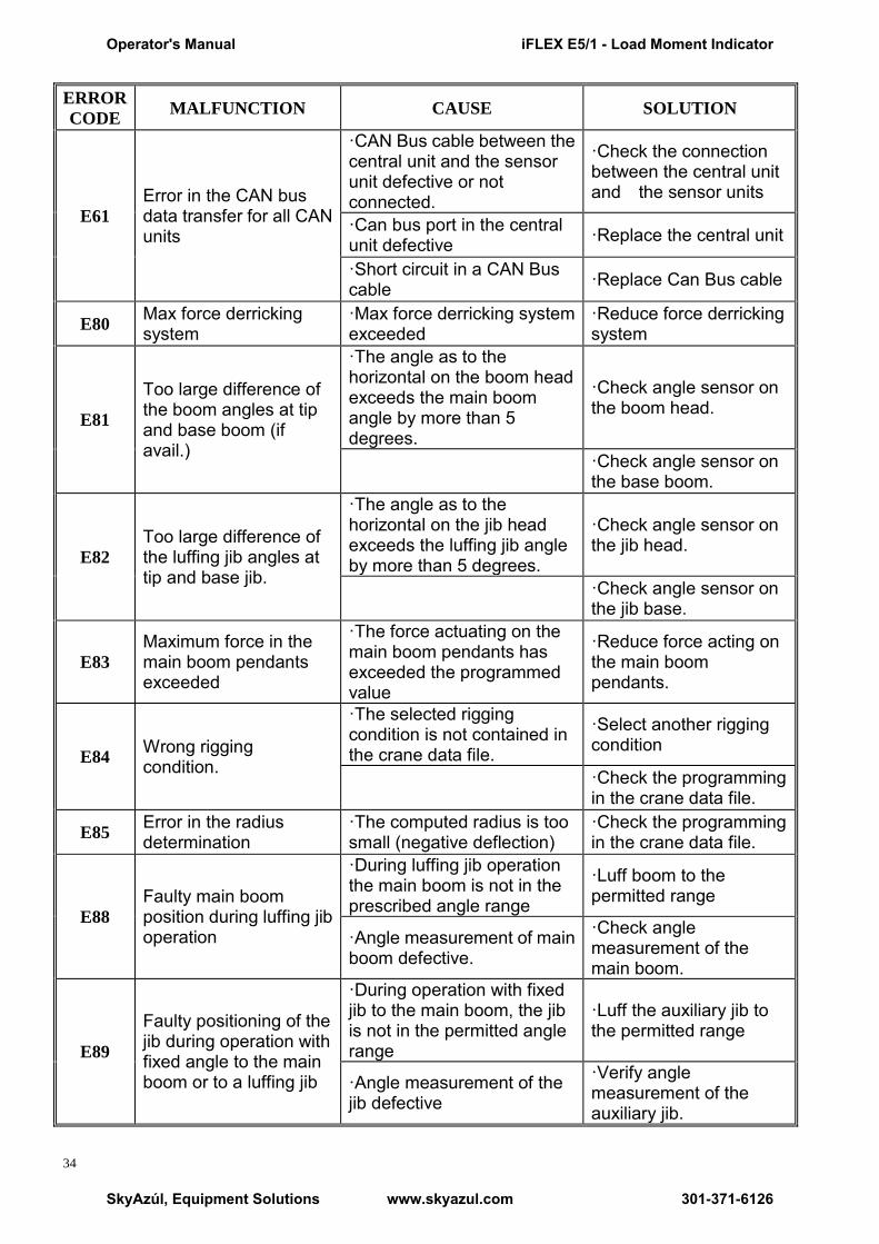
E61
Error in the CAN bus data transfer for all CAN units
·CAN Bus cable between the central unit and the sensor unit defective or not connected.
·Check the connection between the central unit and the sensor units
·Can bus port in the central unit defective ·Replace the central unit
·Short circuit in a CAN Bus cable ·Replace Can Bus cable
E80 Max force derricking system
·Max force derricking system exceeded
·Reduce force derricking system
E81
Too large difference of the boom angles at tip and base boom (if avail.)
·The angle as to the horizontal on the boom head exceeds the main boom angle by more than 5 degrees.
·Check angle sensor on the boom head.
·Check angle sensor on the base boom.
E82
Too large difference of the luffing jib angles at tip and base jib.
·The angle as to the horizontal on the jib head exceeds the luffing jib angle by more than 5 degrees.
·Check angle sensor on the jib head.
·Check angle sensor on the jib base.
E83
Maximum force in the main boom pendants exceeded
·The force actuating on the main boom pendants has exceeded the programmed value
·Reduce force acting on the main boom pendants.
E84 Wrong rigging condition.
·The selected rigging condition is not contained in the crane data file.
·Select another rigging condition
·Check the programming in the crane data file.
E85 Error in the radius determination
·The computed radius is too small (negative deflection)
·Check the programming in the crane data file.
E88
Faulty main boom position during luffing jib operation
·During luffing jib operation the main boom is not in the prescribed angle range
·Luff boom to the permitted range
·Angle measurement of main boom defective.
·Check angle measurement of the main boom.
E89
Faulty positioning of the jib during operation with fixed angle to the main boom or to a luffing jib
·During operation with fixed jib to the main boom, the jib is not in the permitted angle range
·Luff the auxiliary jib to the permitted range
·Angle measurement of the jib defective
·Verify angle measurement of the auxiliary jib.
Operator's Manual iFLEX E5/1 - Load Moment Indicator
SkyAzúl, Equipment Solutions www.skyazul.com 301-371-6126
35
ERROR
CODE MALFUNCTION CAUSE SOLUTION
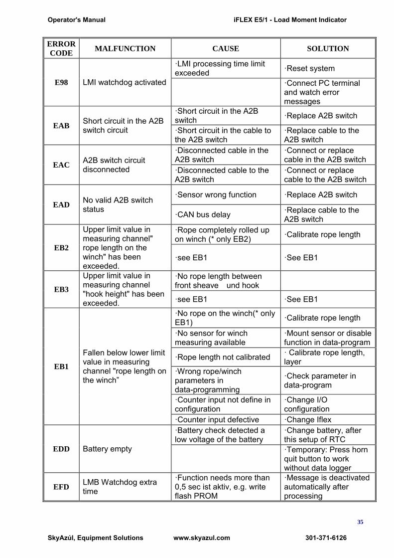
E98 LMI watchdog activated
·LMI processing time limit exceeded ·Reset system
·Connect PC terminal and watch error messages
EAB Short circuit in the A2B switch circuit
·Short circuit in the A2B switch ·Replace A2B switch
·Short circuit in the cable to the A2B switch
·Replace cable to the A2B switch
EAC A2B switch circuit disconnected
·Disconnected cable in the A2B switch
·Connect or replace cable in the A2B switch
·Disconnected cable to the A2B switch
·Connect or replace cable to the A2B switch
EAD No valid A2B switch status
·Sensor wrong function ·Replace A2B switch
·CAN bus delay ·Replace cable to the A2B switch
EB2
Upper limit value in measuring channel" rope length on the winch" has been exceeded.
·Rope completely rolled up on winch (* only EB2) ·Calibrate rope length
·see EB1 ·See EB1
EB3
Upper limit value in measuring channel "hook height" has been exceeded.
·No rope length between front sheave und hook
·see EB1 ·See EB1
EB1
Fallen below lower limit value in measuring channel "rope length on the winch‖
·No rope on the winch(* only EB1) ·Calibrate rope length
·No sensor for winch measuring available
·Mount sensor or disable function in data-program
·Rope length not calibrated · Calibrate rope length, layer
·Wrong rope/winch parameters in data-programming
·Check parameter in data-program
·Counter input not define in configuration
·Change I/O configuration
·Counter input defective ·Change Iflex
EDD Battery empty
·Battery check detected a low voltage of the battery
·Change battery, after this setup of RTC
·Temporary: Press horn quit button to work without data logger
EFD LMB Watchdog extra time
·Function needs more than 0,5 sec ist aktiv, e.g. write flash PROM
·Message is deactivated automatically after processing
Operator's Manual iFLEX E5/1 - Load Moment Indicator
SkyAzúl, Equipment Solutions www.skyazul.com 301-371-6126

Operator’s Manual
SkyAzúl, Equipment Solutions www.skyazul.com 301-371-6126


SkyAzúl, Equipment Solutions www.skyazul.com 301-371-6126
SkyAzúl, Inc. 16 Walnut Street Middletown, MD 21769 Phone 301-371-6126 Fax 301-371-0029 [email protected] www.skyazul.com


