Installation and Commissioning Guide Load Tap Changers, types UZE and UZF with Motor-Drive Mechanism, type BUF 3 Load Tap Changer, type UZG with Motor-Drive Mechanism, type BUL ABB Power T&D Company Inc. Components Division IG 44-503 Maintenance Guide June 30, 1998 New Information
Transcript
Installation andCommissioning Guide
Load Tap Changers, types UZE and UZFwith Motor-Drive Mechanism, type BUF 3
Load Tap Changer, type UZG withMotor-Drive Mechanism, type BUL
ABB Power T&D Company Inc.Components Division
IG 44-503Maintenance Guide
June 30, 1998New Information
This document must not be copied without our written permission, and thecontents thereof must not be imparted to a third party nor be used for any
unauthorized purpose. Contravention will be prosecuted.
Renewal Parts
If renewal parts are required, order them through thenearest ABB Power T&D Company Inc. representative.Please provide the item description and the identificationnumbers (model, style, catalog) from the unit’s name-plate.
Technical Support
If a technical question arises regarding the product de-tailed in this Technical Product Literature contact:
ABB Power T&D Company Inc.Components Division1128 Highway 412 S.Alamo, TN 38001-3813 U.S.A
Phone: (800) 955-8399(901) 696-5561
Fax: (901) 696-5269
Comments
ABB Power T&D Company Inc. continually strives tomake its instruction literature current, accurate, andeasy to understand. Suggestions to improve thisdocument may be sent to: Literature Coordinator fax(901) 696-5269 or use the above mailing address. For areply, please include name, company, phone number,and/or fax number.
DISCLAIMER OF WARRANTIESAND LIMITATION OF LIABILITY
THERE ARE NO UNDERSTANDINGS, AGREEMENTS,REPRESENTATIONS, OR WARRANTIES, EX-PRESSED OR IMPLIED, INCLUDING WARRANTIESOF MERCHANTABILITY OR FITNESS FOR APARTICULAR PURPOSE OTHER THAN THOSESPECIFICALLY SET OUT BY AN EXISTING CON-TRACT BETWEEN THE PARTIES. ANY SUCHCONTRACT STATES THE ENTIRE OBLIGATION OFSELLER. THE CONTENTS OF THIS DOCUMENTSHALL NOT BECOME PART OF OR MODIFY ANYPRIOR OR EXISTING AGREEMENT, COMMITMENT,OR RELATIONSHIP.
The information, recommendations, description, andsafety notations in this document are based on ourexperience and judgement. THIS INFORMATIONSHOULD NOT BE CONSIDERED TO BE ALLINCLUSIVE OR COVERING ALL CONTINGENCIES.If further information is required, ABB Power T&D Com-pany Inc. should be consulted.
NO WARRANTIES, EXPRESSED, OR IMPLIED, IN-CLUDING WARRANTIES OF FITNESS FOR APARTICULAR PURPOSE OR MERCHANTABILITY, ORWARRANTIES ARISING FROM COURSE OF DEAL-ING OR USAGE OF TRADE, ARE MADE REGARDINGTHE INFORMATION, RECOMMENDATIONS, DE-SCRIPTIONS AND SAFETY NOTATIONS CONTAINEDHEREIN. In no event will ABB Power T&D CompanyInc. be responsible to the user in contract, in tort(including negligence), strict liability or otherwise for anyspecial, indirect, incidental or consequential damage orloss whatsoever including but not limited to damage toor loss or use of equipment, plant or power system,cost of capital, loss of profits or revenues, cost of re-placement power, additional expenses in the use ofexisting power facilities, or claims against the user byits customers resulting from the use of the information,recommendations, description, and safety notationscontained herein.
Recommended PracticesABB Power T&D Company Inc. recommends careful consideration of the following factorswhen installing load tap changers.
Before you install a unit, make sure that the personnel doing the job have read and fullyunderstood the Installation and Maintenance documents provided with the unit.
To avoid damaging the unit, never exceed the operating limits stated in deliverydocuments and on rating plates.
Do not alter or modify a unit without first consulting ABB.
Follow local and international wiring regulations at all times.
Use only factory authorized replacement parts and procedures.
WARNING, CAUTION and NOTE
WARNING A WARNING provides information which, if disregarded, could cause injury ordeath.
CAUTION A CAUTION provides information which, if disregarded, could cause damage tothe equipment.
NOTE: A NOTE provides additional information to assist in carrying out thework described.
Safety Precautions WARNING
Unused transformer oil is slightly harmful. Fumes from unused warm oil mayirritate the respiratory organs and the eyes. After long and repeated contactwith transformer oil skin becomes very dry.
Used load tap changer oil from diverter switch housings and selector switchhousings contains harmful substances. Fumes are irritating to the respiratoryorgans and the eyes and are very easily set on fire. Used transformer oil maywell be carcinogenic.
Avoid contact with the oil as much as possible and use oil-tight protectivegloves when handling the oil.
First aid:Skin contact: Wash the hands. Use skin cream to counteract drying.In the eyes: Rinse the eyes in clean water.Swallowing: Drink water or milk. Avoid vomiting. Call a doctor.
Collect used oil in oil drums.continued on the next page.
iii
Waste and cleaning up: Should be absorbed by an absorber. Treat it ashazardous to the environment.
Upon fire: The fire should be extinguished by using powder, foam or carbonacid.
WARNING The motor-drive mechanism must not be installed in any explosiveatmosphere. The electrical equipment creates sparks which can cause anexplosion.
WARNING Before any work is carried out on the load tap changer:Make sure that the transformer is disconnected and that earthing is properlycarried out. Obtain a signed certificate from the engineer in charge.
WARNING Before starting any work in the load tap changer the protective motor switchand the LOCAL/REMOTE switch must be set at ”0”.
WARNING Before starting any work inside the motor-drive mechanism, the auxiliarypower must be switched off.
N.B. The motor, contactors and heating element may be energized fromseparate sources.
During Drying of the Transformer
CAUTION The load tap changer must not be included in the vapour phase drying processof the transformer. For permissible pressure and temperature at the rear duringdrying process, see chapter 3.
iv
During Oil Filling
WARNING When oil that has been used in a selector switch compartment is pumped out,conducting tubes and hoses that are earthed should be used to avoid the riskof explosion due to the gases produced by the arcs during service.
CAUTION Do not fill oil into the load tap changer if the transformer tank is under vacuumand the load tap changer is not.
CAUTION Do not fill oil into the transformer tank if the load tap changer is under vacuumand the transformer tank is not.
CAUTION The oil level in the oil conservator of the load tap changer should never be abovethe oil level in the oil conservator of the transformer.
After Oil Filling
CAUTION Do not energize the transformer earlier than three hours after oil filling inatmospheric pressure. This waiting period is needed to allow airbubbles todisappear.
During Service
WARNING Small amounts of explosive gases will always come out from the breathingdevices (dehydrating breather or one-way breather). Make sure that no openfire, hot surfaces or sparks occur in the immediate surrounding of thebreathing devices.
v
Mounting of Gaskets
CAUTION Sealing surfaces and gaskets must be clean and undamaged. Diametricallyopposed bolts in sealing joints must be tightened alternately several times,beginning with a low tightening torque and finally with the recommendedtightening torque as described in section 1.6 Tightening Torque, in this guide.
WARNING If a failure in power supply occurs during operation, the operation will becompleted when the power returns.
WARNING The hand crank must not be inserted during electrical operation.
WARNING The motor drive can move suddenly when power is restored after a powerfailure.
CAUTION After a pressure relay trip, follow the instructions in the chapter ”PressureRelay” in the Repair Guide.
CAUTION The pressure relay is a calibrated monitoring instrument. It must be handled withcare and protected against careless handling or any kind of mechanical damage.
4 Installation on the Transformer _____________________________ 164.1 Attaching the Load Tap Changer to the Transformer ____________ 164.1.1 Welding_______________________________________________ 164.1.2 Bolting ________________________________________________ 164.1.3 Assembly of Accessories _________________________________ 184.1.4 Retightening____________________________________________ 184.2 Connection of the Regulating Winding
of the Transformer, Type UZE/UZG ________________________ 184.3 Connection of the Regulating Winding of the Transformer, Type UZF 184.4 Connection to the Oil Conservator___________________________ 20
5 Pressure Relay__________________________________________ 215.1 General________________________________________________ 215.2 Installation_____________________________________________ 215.3 Checking when Commissioning the Transformer _______________ 22
6 Oil Filling ______________________________________________ 236.1 Filling Methods and Restrictions ____________________________ 236.2 Filling at Atmospheric Pressure _____________________________ 236.3 Filling under Vacuum _____________________________________ 246.4 Correct Oil Level ________________________________________ 24
7 Electrical Connection and Testing ___________________________ 257.1 General________________________________________________ 257.2 Connecting and Testing ___________________________________ 257.3 Electrical Tests on Transformer ____________________________ 267.4 After Energizing _________________________________________ 26
7
8 Oil Level during Transport _________________________________ 278.1 Transformer Filled with Oil ________________________________ 278.1.1 Conservator Mounted ____________________________________ 278.1.2 Conservator Dismounted __________________________________ 278.1.3 UZE/UZG with Oil Expansion Volume in the Tank _____________ 278.2 Transformer Drained _____________________________________ 278.2.1 Conservator Mounted ____________________________________ 278.2.2 Conservator Dismounted __________________________________ 278.2.3 UZE/UZG with Oil Expansion Volume in the Tank _____________ 27
9 Commissioning__________________________________________ 289.1 Reassembly ____________________________________________ 289.2 Oil Filling ______________________________________________ 289.2.1 Dehydrating Breather ____________________________________ 289.3 Electrical Connection and Testing ___________________________ 289.3.1 Motor Protection ________________________________________ 289.3.2 Counter _______________________________________________ 299.3.3 Position Transmitter and other Multi-Position Switches __________ 299.3.4 Light__________________________________________________ 299.3.5 Heater________________________________________________ 299.3.6 Pressure Relay__________________________________________ 299.4 Putting into Operation ____________________________________ 29
APPENDIX A. Delivery of Load Tap Changer without Tank _______ A1
A1. Introduction ____________________________________________ A1APPENDIX B. Assembly of Shafts between UZG and BUL ________ B1
B2. Mounting of the Motor-Drive Mechanism _____________________ B2B3. Mounting of Shaft System _________________________________ B2B3.1 Drive Shaft_____________________________________________ B2B3.2 Mounting of Drive Shaft __________________________________ B4B4. Checking Alignment of Load Tap Changer
and Motor-Drive Mechanism_______________________________ B5B4.1 Preparation_____________________________________________ B5B4.2 Checking Alignment______________________________________ B5B5 Operation Test __________________________________________ B5B6 Closing________________________________________________ B5B7 Continuation of Installation_________________________________ B5
8
1 Introduction
1 IntroductionThe on-tank concept of load tap changer, realized by ABB Components Sweden in theUZ range, is unique. The design offers advantages in installation and maintenance. Thewhole device is delivered installed in a tank that is simply mounted onto the transformertank. For the UZE and UZF, the motor-drive mechanism is included as a part of theLTC (see fig. 1). For the UZG, the motor-drive is delivered as a separate item and isconnected to the LTC by a driving shaft.
Fig. 1. General arrangement of load tap changer UZF
It is easy to access all parts of the load tap changer for maintenance and repair. Afterdraining the oil, you simply unbolt and open the front cover to access any part you mayneed to inspect or replace.
9
Lifting eyeConnection to oil conservator
load tap changer tank
Oil valve
Pressure relay
Terminalsforconductors
Attachment flange totransformer tank
Cover for access to conductors,UZF only
fm_00069
10
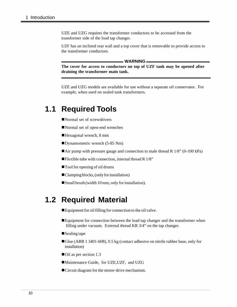
UZE and UZG requires the transformer conductors to be accessed from thetransformer side of the load tap changer.
UZF has an inclined rear wall and a top cover that is removable to provide access tothe transformer conductors.
WARNING The cover for access to conductors on top of UZF tank may be opened afterdraining the transformer main tank.
UZE and UZG models are available for use without a separate oil conservator. Forexample, when used on sealed tank transformers.
1.1 Required ToolsnNormal set of screwdrivers
nNormal set of open-end wrenches
nHexagonal wrench, 8 mm
nDynamometric wrench (5-85 Nm)
nAir pump with pressure gauge and connection to male thread R 1/8” (0-100 kPa)
nFlexible tube with connection, internal thread R 1/8”
nTool for opening of oil drums
nClamping blocks, (only for installation)
nSmall brush (width 10 mm, only for installation).
1.2 Required MaterialnEquipment for oil filling for connection to the oil valve.
nEquipment for connection between the load tap changer and the transformer whenfilling under vacuum. External thread KR 3/4” on the tap changer.
nSealing tape
nGlue (ABB 1 3401-608), 0.5 kg (contact adhesive on nitrile rubber base, only forinstallation)
nOil as per section 1.3
nMaintenance Guide, for UZE,UZF, and UZG
nCircuit diagram for the motor-drive mechanism.
1 Introduction
11
1.3 OilThe oil quality should be of Class II according to IEC publication 296.
Table 1. Weight of Oil in kg.
Type designation LTC with separate LTC with expansionconservator 1) volume in the tank
WARNING Do not energize the transformer until oil has been filled as per chapter 6, OilFilling, in this guide.
1.4 Oil ConservatorThe load tap changer is sometimes connected to an oil conservator. ABB recommendsthe use of a separate conservator for the load tap changer with both oil and air sideseparated from the main conservator of the transformer.
The volume of the conservator should be such that there is oil left in the conservatoreven at the lowest oil temperature expected and such that no flooding can occur at thehighest oil temperature expected.
A suitable dimension of the tube for connection to the conservator is an inner diameterof approximately 20 mm. The tube should be inclined at least 3 degrees to avoid gascushions in the tube. A valve in the connection to the conservator is recommended.
The conservator must be equipped with a breathing device that does not allow moist airinto the conservator and that allows the gas from the arcs to disappear.
The conservator should also be equipped with an oil level indicator, and an alarmcontact for low oil level is recommended.
1 Introduction
12
1 Introduction
Fig. 4. UZF with built-on oil conservator
fm_00089
fm_00118
tc_00182
Fig. 3. UZE with oil expansion volume in the tankUZG is similar to this design.
Fig. 2. UZE with separate oil conservator
13
1 Introduction
1.5 WeightsTable 2 contains the approximate weights of all the models in the UZ range of load tapchangers. The weight of the motor-drive mechanism is included in the overall weightexcept for UZG where it is shown separately.
Table 2. Weights for UZ load tap changers in kg.
Load tap changer Tap changerType designation without oil 1,2
1 The weight of the BUF motor-drive mechanism is approximately 110 kg2 The weight of the UZF includes the weight of the conservator usually delivered with the load
tap changer
Load tap changer Tap changer BULType designation w ithout oil motor-drive
1.6 Tightening TorqueThe following tightening torques are recommended: M6, 10 Nm ±10 %
M8, 24.5 Nm ±10 %M10, 49 Nm ±10 %M12, 84 Nm ±10 %
unless otherwise stated in this guide.
2 Receiving2.1 Unpacking
Check that all pieces are free from transport damage. If there is visible damage acareful investigation must be carried out.
Lift the load tap changer and the motor drive BUL if included, using the lifting eyes onthe top.
2.2 Inspection upon Receiving1.Check that there is no visible damage.
2.Open the door of the cabinet of the motor-drive mechanism and check that themotor-drive mechanism is free from damage.
3.If transport damage is found, and it is adjudged that correct operation of theload tap changer is not possible, a damage report should be sent to theinsurance company. It is also recommended that photographs be taken of thedamaged details. Mark the photos with the serial number of the load tapchanger and send them to ABB for comments.
4.Check that the quantity delivered, the type designation and the serial number agreewith the delivery documents, e.g. the packing list or ABB’s ordering acknowledge-ment. The serial number is stamped on the rating plate.
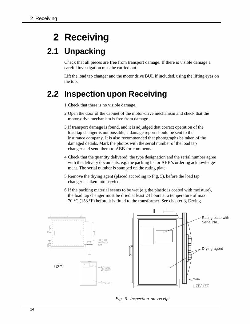
5.Remove the drying agent (placed according to Fig. 5), before the load tapchanger is taken into service.
6.If the packing material seems to be wet (e.g the plastic is coated with moisture),the load tap changer must be dried at least 24 hours at a temperature of max.70 °C (158 °F) before it is fitted to the transformer. See chapter 3, Drying.
2 Receiving
Rating plate withSerial No.
Fig. 5. Inspection on receipt
Drying agent
14
fm_00070
UZE/UZF
UZG
15
2.3 Temporary Storage before AssemblyIf the load tap changer is not to be installed on the transformer immediately, once thedelivery has been approved the load tap changer must be kept warm and dry.Let the unit be kept in its plastic enclosure and leave the drying agent until assembly.
3 DryingDrying of the load tap changer is normally not required, see section 2.2, step 6.
The following temperatures and pressures between the load tap changer tank and thetransformer tank are allowed when drying:
Pressure Standard Load Tap Changer Load Tap Changerwith reinforced barrier 1
Zero Up to 115 oC (239 oF) on the Up to 115 oC (239 oF) on thetransformer side. transformer side.Up to 90 oC (194 oF) inside the tank. Up to 90 oC (194 oF) inside the tank.
Up to 100 kPa Up to 60 oC (140 oF). Up to 90 oC (194 oF).
100–150 kPa Not allowed. Up to 60 oC (140 oF).
1 For use on sealed tank transformers
The temperature inside the motor drive cabinet must not exceed 70 °C (158 °F).
During or after drying the load tap changer must not be operated until it has been filledwith oil. The motor-drive mechanism should not be included in a vacuum process, asthe process would remove the grease necessary for operation.
3 Drying
4 Installation on the Transformer
4 Installation on the Transformer CAUTION
The load tap changer must not be included in the drying process of thetransformer.
The load tap changer is either bolted or welded to the transformer tank, seesection 4.1. See Appendix B for assembly of shafts and motor-drive BUL for LTCtype UZG
4.1 Attaching the Load Tap Changer tothe Transformer
4.1.1 WeldingFor welding the load tap changer to the transformer tank, use fillet weld witha > 4 mm (Fig. 6).
16
Fig. 6. Welding detail
4.1.2 BoltingA set of cork-rubber gaskets is provided to seal against the transformer tank.
When you install the load tap changer, the gasket should be glued as described below.
Tighten the bolts by approximately 60 Nm torque.
Ensure that the surfaces being in contact with the gaskets are clean and free fromgrease and oil.
fm_00071
load tap changer flange
a > 4 mm
Transformer tank
17
4 Installation on the Transformer
After spreading the glue let it dry at room temperature for a minimum of 10 minutesand a maximum of 30 minutes.
Keep the gaskets in the correct position by using clamping blocks for a minimum of3 hours.
Glue the inner gasket bands only, both to the load tap changer flange side and to thetransformer-tank flange side.
The required amount of glue (ABB 1 3401-608) is 0.5 kg.
Do not glue gaskets at temperatures below 0 °C (32 °F).
NOTE: ABB glue 1 3401-608 is a contact adhesive of nitrile rubber base.
May consist oftwo gaskets
A
AA
Supporting gasket
Sealing gasket
Corner gasket
View A – A
26
Fig. 7. Gluing the gasket
fm_00072
10
A
After cleaning, stick the gaskets to the transformer tank flange (Fig. 7) with ABB glue1 3401-608, by brushing glue on both the gasket and the flange.
4.1.3 Assembly of AccessoriesAll details which have been removed for the transport are specified on the packing list.The openings on the load tap changer are then sealed by transport covers.
1.Remove the transport covers.
2.Check the O-rings. Make sure they are pressed into the bottom of the groove on theflanges.
3.Assemble the accessories. Tightening torque for the nuts as per section 1.6.
4.1.4 RetighteningWhen a gasket is subjected to the pressure from the flange bolts it will change itsshape or settle. This reduces the pressure on the bolts, making them loose.
The settling effect will increase at higher temperatures. For this reason retightening isrequired.
Retighten one day after assembly. Retighten again after the transformer has been inservice for about two weeks to let the gaskets settle at service temperature.
The retightening torque should again be approximately 60 Nm.
4.2 Connection of the Regulating Windingof the Transformer, Type UZE and UZGOn UZE and UZG the winding has to be connected from the rear. The cable lugs canbe either crimped or brazed. The free distance between the cable lugs for electricallyadjacent contacts must be at least 7 mm. Tightening torque is 38 Nm. For star pointdesign, attach the neutral connection as shown in Fig. 8 and the connection diagram.
4.3 Connection of the Regulating Windingof the Transformer, Type UZFThe top cover is intended to be used when connecting the transformer’s regulatingwinding leads to the load tap changer terminals.
Remove the cover and connect the leads. Tightening torque is 38 Nm. For star-pointdesign, attach the neutral connection as shown in Fig. 8 and the connection diagram.Bolt on the cover. Tightening torque is 42 Nm.
If the oil conservator is to be installed on the top of the load tap changer, connect theregulating winding leads before installing the oil conservator.
4 Installation on the Transformer
18
4 Installation on the Transformer
19
Fig. 8. Assembly of the neutral connection
Neutral connection
fm_000196
20
4 Installation on the Transformer
Fig. 9. Attachment flange for oil conservator
4.4 Connection to the Oil ConservatorSee Fig. 9.
Remove the transport cover from the flange for the oil conservator. Check that theO-ring is in place on the flange and connect the pipe to the oil conservator.
In cases where the oil conservator is installed directly on the top of the load tapchanger, install the oil conservator directly on the flange with the connection sealed byan O-ring that is left on the flange when the transport cover is removed. After that, theother bracket of the conservator is mounted to the tank.
For UZ with normal barrier, the oil level difference between load tap changer andtransformer should be a maximum of 1.2 m. For a reinforced barrier, the oil leveldifference may be 8 m.
CAUTION Where the conservator is common to the transformer and the load tap changer,an oil filter must be placed in the pipe between the load tap changer and theconservator.
Filter with housing can be ordered from ABB orderingNo. LL 114 004-AP.
The tank of the load tap changer is supplied with a pressure relay. In the event ofoverpressure in the tank the relay, if correctly connected, will trip the transformer’smain circuit breakers. It is also recommended to connect the pressure relay in the tripcircuit of the power supply during testing of the transformer.
CAUTION After a pressure relay trip follow the instructions under chapter ”PressureRelay” in the Repair Guide.
CAUTION Taking the transformer into service after a pressure relay trip without openingthe front cover and carrying out a careful investigation of the active part andrepairing any faults may cause severe damage to the load tap changer and thetransformer.
The pressure relay can easily be tested by applying air pressure, using a pump, to thetest tap on the valve. The handle can be padlocked in the service position.
CAUTION The pressure relay is a calibrated monitoring instrument. It must be handled withcare and protected against careless handling or any kind of mechanical damage.
5.2 InstallationRemove the cover from the pressure relay terminal box and connect the cables to theterminal block.
The cable gland includes an O-ring seal between the gland and the pressure relayhousing.
If the gland has to be changed to another type, the seal against the housing must besecured by a gasket or sealing liquid (e. g. Loctite 275).
CAUTION Tighten the cable gland with care, torque max. 5 Nm.
5 Pressure Relay
22
Information plate
5.3 Checking when Commissioning theTransformer
����
Valve handle
Test tap (R 1/8”)fm_00117
Fig. 10. Pressure relay
1. Set the valve handle in the test position as shown on the information plate.
2. Connect the air pump and the pressure gauge to the test tap on the pressure relay.
3. Raise the pressure until the pressure relay trips the circuit breakers for thetransformer.
4. Read the pressure on the manometer and check against the pressure stated on theinformation plate. Max. permitted deviation is ± 10 %.
5. Check that the alarm signal disappears when the pressure is lowered.
6. After finishing the check, turn the valve handle back to the service position.
23
6 Oil Filling6.1 Filling Methods and Restrictions
Oil filling can be carried out at atmospheric pressure or under vacuum. The wallbetween the load tap changer and the transformer tank is designed to withstandvacuum on one side and atmospheric pressure on the other side. Having vacuum onone side and the pressure of an oil column on the other side is not permitted.
UZE and UZG can be delivered with an oil expansion volume in top of the tank. Thedesign of UZF does not allow an oil expansion volume in the tank. Instead, UZF can bedelivered with a built-on oil conservator. See also Figs. 2, 3 and 4.
Oil filling may be carried out in different ways depending on what the transformermanufacturer considers convenient, as long as the above rules are complied with andthe load tap changer is filled with oil to the correct level.
The methods below are recommended, and if they are followed in detail no pressurelimits will be exceeded.
6.2 Filling at Atmospheric Pressure1.Open the conservator valve, if any.
2.Dismantle the pipe to the breather. Or, if simpler, remove the air relief valve(one way breather) or the dehydrating breather.
3.Connect the pump to the oil valve on the load tap changer tank. For dimensionsee the dimension drawing. Open the valve and pump in oil to the correct levelshown on the oil level indicator. For correct oil level, see section 6.4.
4.Shut the oil valve and disconnect the pump.
5.Reassemble the pipe or the breather. The connections must be airtight; thereforeuse sealing tape on the threads and O-rings in the flanges.
When the transformer and the load tap changer have a common oil conservator,a filter in the connection between the load tap changer and the conservator is needed.
1.The conservator valve should be shut.
2.Open the air release valve on the oil filter housing.
3.Connect the pump to the oil valve on the load tap changer tank. Open thevalve and pump in oil. Stop the pump when oil reaches the air release valve.
4.Shut the oil valve and the air release valve and disconnect the pump.
5.Open the conservator valve.
CAUTION Do not energize the transformer earlier than three hours after oil filling inatmospheric pressure. This waiting period is needed to allow airbubbles todisappear.
6 Oil Filling
24
6 Oil Filling
6.3 Filling under VacuumOil filling under vacuum is not necessary. If it is to be carried out, the load tap changerand the transformer tank should be put under vacuum simultaneously.
It is assumed that a vacuum-proof conservator is in use.
1.Open the conservator valve, if any.
2.Dismantle the pipe to the breather, or, if simpler, remove the air relief valve or thedehydrating breather.
3.Connect the transformer to the conservator for the load tap changer or to the top ofthe load tap changer via the breather.
4.Apply vacuum.
5.Connect the oil filling equipment to the oil valve on the load tap changer tank. Openthe valve and let oil into the tank until the correct level is shown on the oil levelindicator. For correct oil level see section 6.4.
6.Shut the oil valve and disconnect the filling equipment.
7.When filling of the transformer is completed disconnect the vacuum pump and let airinto the conservator or expansion volume.
8.Reassemble the pipe or the breather. The connections must be airtight; therefore usesealing tape on the threads and O-rings in the flanges.
6.4 Correct Oil LevelFor installations where the load tap changer and the transformer tank have a commonoil conservator, the instructions for the transformer should be used.
If possible, the oil levels of the oil conservators of the transformer tank and theload tap changer should be the same. The oil level of the oil conservator of theload tap changer should in no case be higher than the oil level of the transformer oilconservator.
At +25 oC (77 oF), oil is filled to the level where the pointer of the oil level indicatorpoints half-way between MIN and MAX.
For other temperatures than +25 oC (77 oF), proceed as follows:
– For every 10 oC (18 oF) increase of temperature, adjust the oil level upwards a tenthof the scale range of the oil level indicator.
– For every 10 oC (18 oF) decrease of temperature, adjust the oil level downwards atenth of the scale range of the oil level indicator.
7 Electrical Connection and Testing
7 Electrical Connection andTesting
7.1 GeneralBefore the transformer is energized, tests have to be carried out to make sure that allmechanical and electrical connections are correct, and to check the proper functioningof the motor-drive mechanism and the load tap changer.
When testing the transformer, the load tap changer can be operated either by the handcrank or electrically. When operating electrically the drive mechanism is connected asper section 7.2.
7.2 Connecting and TestingFor bolted on design, connect the earthing terminal on the load tap changer to thetransformer tank.For the BUL motor-drive, connect the earthing terminal to the transformer tank.
Connect the motor supply and the control supply to the correct terminals in the motor-drive mechanism as shown by the circuit diagram supplied with the load tap changer.
Operate the motor-drive mechanism by means of the hand crank to one of thepositions in the middle of the range, but not in a through position (= a position with aletter in).
Turn the control selector-switch to position LOCAL. Then give an impulse for RAISEoperation. If the phase sequence (three-phase supply) is wrong, the motor-drivemechanism will start in LOWER direction. The motor-drive mechanism will stop whenit has made approximately half of the complete operation and it will operate back andforth without the load tap changer changing position until the control selector switch isturned to position ”0”. If the phase sequence is wrong, reverse two of the motor supplycables in order to get the correct sequence.
WARNINGDangerous voltage.
Operate the load tap changer electrically. For UZE/UZF check that the flywheel in themotor-drive mechanism stops with the brake between the outer marks on the flywheel.For any adjustment needed, see Maintenance Guide for UZE/UZF/UZG.
For BUL:
Run the motor-drive mechanism and check that the center of the notch in the cam discstops within ±2 mm from the center of the roller on the brake arm, see Fig. B4. If itdoes not stop within the tolerances, adjust the breaking force with the adjusting screwin the lower end of the brake arm. Loosen the lock nut. Tightening the screw(clockwise) makes the stop earlier and loosening the screw (anticlockwise) makes the
25
26
7 Electrical Connection and Testing
stop later. Tighten the lock nut after the adjustment.
Operate the driving mechanism electrically between the end positions. Check the endstops. When trying to operate it electrically beyond the end position, the motor shouldnot start. Check the mechanical end stop by trying to hand crank it beyond the endposition. After a couple of turns on the hand crank it should be mechanically stopped.Hand crank back to the end position (where the indicator flag is white). Operate theload tap changer electrically to the other end position and repeat the test procedureabove.
CAUTION The transformer should in no case be energized with an end stop out of order.
7.3 Electrical Tests on TransformerAcceptance tests on the transformer or commissioning can now be performed.
7.4 After Energizing
WARNING Before any work is carried out on the load tap changer:Make sure that the transformer is disconnected and that earthing is properlycarried out. Obtain a signed certificate from the engineer in charge.
8 Oil Level during Transport
8 Oil Level during TransportThe following adjustment of the oil level must be carried out when the load tap changeris to be transported.
CAUTION Take care to avoid ingestion of moist air when oil is drained. If the ambient air ismoist, let incoming air pass through a dehydrating breather with slow air flow toobtain proper dehydration.
8.1 Transformer Filled with Oil8.1.1 Conservator Mounted
The load tap changer should be filled with oil and connected to its conservator.
8.1.2 Conservator DismountedDrain about 20 % of the oil from the load tap changer. Oil weights according to section1.3.
Close the opening to the conservator with a transport cover.
8.1.3 UZE/UZG with Oil Expansion Volume in the TankThe load tap changer should be filled with oil.
8.2 Transformer Drained8.2.1 Conservator Mounted
Drain the oil from the load tap changer. Keep the connections to the conservator.
8.2.2 Conservator DismountedDrain the oil from the load tap changer. Close the opening to the conservator with atransport cover.
8.2.3 UZE/UZG with Oil Expansion Volume in the TankDrain the oil from the load tap changer.
WARNING The motor-drive mechanism must be protected against condensation.Energize the heater when power is available. When not, put drying agentinside the motor drive cabinet and seal the vents.
27
28
9 Commissioning
9 CommissioningThis section describes tasks to be carried out when the transformer is being installedand tested on site.
CAUTION The motor-drive mechanism must be protected against condensation.
Energize the heater when power is available. When not available, put dryingagent inside the motor-drive cabinet and seal the vents.
9.1 ReassemblyReassemble the conservator and all other accessories which may have beendismantled for the transport. Remember the O-rings in the flanges.
9.2 Oil FillingSee chapter 6.
9.2.1 Dehydrating BreatherIf the breather has an oil trap, fill oil to the marked level.
9.3 Electrical Connection and TestingDo all wiring work and perform the appropriate tests as described in chapter 7.
9.3.1 Motor ProtectionThe function of the protective motor switch should be checked. For three-phase ACmotors, remove one of the phase fuses and check the function time of the protectivemotor switch by a RAISE or LOWER operation. The protective motor switch shouldrelease within 60 seconds at a current setting equal to the rated current of the motor atthe actual voltage.
If the protective motor switch does not trip within 60 seconds, adjust the currentsetting. Repeat the test when the motor is cold.
29
9 Commissioning
9.3.2 CounterCheck that the counter functions upon RAISE and LOWER operations.
9.3.3 Position Transmitter and other Multi-PositionSwitchesCheck the function of the position transmitter and other multi-position switches.
9.3.4 LightCheck that the light is switched on when the door is opened and goes out when thedoor is closed.
9.3.5 HeaterSwitch off all power supplies and feel by hand that the heater has been warmed upduring earlier tests. Switch on the power afterwards.
9.3.6 Pressure RelayCheck the function as per section 5.3.
9.4 Putting into OperationPut the LOCAL/REMOTE switch to REMOTE.
Make sure that no tools or foreign objects are left in the motor drive cabinet. Close thedoor.
WARNING The motor power voltage is dangerous.
Protective motor switches for DC motors or single-phase AC motors are not necessaryto test.
APPENDIX A.Delivery of Load Tap Changer WithoutTank
A1 IntroductionDelivery of the Load Tap Changer Without Tank
The UZ range of load tap changers can be delivered without the tank. In these cases,the transformer manufacturer designs the tank as an integral part of the transformertank.For such cases, please contact ABB for the appropriate welding and mountinginstructions.
Appendix A1 Introduction
A1
APPENDIX B.Assembly of Shafts between UZG and BUL
B1 IntroductionThe load tap changer type UZG does not include a motor-drive mechanism on the maintank. The motor-drive mechanism BUL is a separate unit. Since the BUL does notincorporate the spring battery system, flywheel, and brake, these are mounted in a gearbox on the side of the load tap changer tank. The BUL is then connected to the gearbox by a shaft.
Note: As the load tap changer and motor drive mechanism are delivered separately,they are locked in the same service position at delivery. These locking plates should bekept in place until the shaft system is being connected.
Appendix B1 Introduction
B1
Figure B1Positioning of locking plates
B2
Appendix B2. Mounting of the Motor-Drive Mechanism, 3. Mounting of Shaft System
B2 Mounting of the Motor-DriveMechanismProceed as follows:
Mount the motor-drive mechanism onto the transformer.
The mounting holes on the transformer should be leveled within 1 mm to line up withthe mounting holes in the motor-drive back plate. If adjustment is needed, shims shouldbe used.
Note: The load tap changer is mounted according to section 4 of the main doucment.
WARNINGDo not energize the transformer before the load tap changer and motor-drivemechanism are correctly assembled.
B3 Mounting of Shaft System
B3.1 Drive ShaftThe external drive shaft consists of a square tube and shall be connected to thespherical shaft end on the gearbox and motor-drive mechanism by means of twocoupling halves. The square shaft and protective tubes must be cut before mounting.
CAUTIONBefore mounting of shaft and couplings, everything must be cleaned and greasedfor correct function and to avoid corrosion.
Apply a thin layer of grease, GULF-718EP Synthetic grease or Mobilgrease 28 orSHELL-Aero Shell Grease 22 to all spherical shaft ends.
CAUTIONThe motor-drive mechanism and load tap changer shall have the same indicatedtap position.
The inclination of the shaft (the square tube) must not be more than 4o (=70mm forevery 1000 mm shaft length).
NOTE: The tubes around the shaft and couplings are for protection.
The arrangement of the driving shaft system is shown in Fig. B2.
B3
Appendix B3 Mounting of Shaft System
Figure B2
Mounting of Drive-Shaft
B4
Appendix B4. Checking Alignment
B3.2Mounting of Drive-ShaftSee figure B2
Before starting check that the motor-drive mechanism is in the exact position and the loadtap changer is on the same position.
The exact position for the BUL is when the roller on the brake arm is in the notch of the camdisc see fig B4. The position of the load tap changer see B4.2
1. Determine the dimension K2 between the spherical shaft ends. Cut the square tube to the dimension LA2=K2- 6 mm, and remove burrs2. Cut the protective tubes to the dimension LB2 according to the table below.
NOTE: If K2>600 the mounted tubes shall overlap each other at least 300 mm.Dismounting and inspection of the couplings shall be possible when one of the tubes ispushed into the other.
3. Mount the coupling halves, screws, and washers, tightening torque 10Nm. Begin withscrews A, see Fig B3 on one end of the square shaft, then put two protective tubes (thetube with greater diameter upwards) and hose clips over the square shaft and connect theshaft to the motor-drive.
Figure B4
Cam Disk
Roller on Brake Armin the Notch of theCam Disk
Brake Arm
Lock Nut
Adjusting Screw
Brake Disk
Coupling Half
Figure B3
Square Shaft
Washer
Screw
A
A
B5
Appendix B5. Operation Test, 6. Closing, 7. Continuation of Installation
4. Remove the locking plate on the load tap changer.
5. Mount the coupling halves of the other end of the drive-shaft perpendicular to the couplingsalready assembled on the shaft, leaving about 2 mm axial play.
6. Mount the protective tubes and clamp them with the hose clips.
7. Remove the locking plate on the motor-drive mechanism.
NOTE: The locking devices for the gear box and the motor-drive mechanism must be remountedif the shafts are dismounted for transportation.
B4 Checking Alignment of Load TapChanger and Motor-DriveMechanism
It is important to check that the load tap changer and the motor-drive mechanism are onthe same position before operating the motor-drive mechanism. It is also necessary tocheck that the brake stops the flywheel in the correct position.
WARNINGDo not energize the transformer with the load tap changer out of alignment!
B4.1 PreparationOpen the front cover of the load tap changer, remove the cover plate for the gear box,and open the door to the motor-drive mechanism.
B4.2 Checking AlignmentCheck the position of the motor-drive mechanism on its indicating plate. Check that themoving arm of the load tap changer and the reversing switch is in the positioncorresponding to the position of the motor-drive mechanism. This can be seen bylooking at the single phase connection diagram.
B5 Operation TestSee section 7.
B6 ClosingBefore closing the front cover of the load tap changer, make sure that no foreignobjects, tools, wires, rags, etc., are left in the tank.
Close the front cover of the load tap changer, assemble the cover plate for the gearbox. Tightening torque for the dome nuts should be approximately 42 Nm.
B7 Continuation of InstallationContinue the installation and commissioning according to the main document.


![[XLS]test.nhb.org.intest.nhb.org.in/Urban_Housing/4041 statutory Towns.xlsx · Web view502 802681 27 502 802682 27 503 802683 27 503 802684 27 503 802685 27 503 802686 27 503 802687](https://static.documents.pub/doc/80x56/5ab1742b7f8b9abc2f8cb599/xlstestnhborg-statutory-townsxlsxweb-view502-802681-27-502-802682-27-503-802683.jpg)


![Door InstallatIon - Woodfold | Custom Accordion Doors · 2019-10-03 · Woodfold Mfg., Inc P.O. Box 346 Forest Grove, OR 97116 Voice [503] 357-7181 Fax: [503] 357-7185 Door InstallatIon](https://static.documents.pub/doc/80x56/5e7886a8294bff569c3fd2c0/door-installation-woodfold-custom-accordion-doors-2019-10-03-woodfold-mfg.jpg)


