Revision B.10; 22 Jan. 03 Liebert Monitoring Group - Development SiteScan IGM Reference Document Including Modbus and BACnet object Listings This reference document is based on the assumption that the connecting unit is SiteScan 2000 ready and is using the SiteScan 2000 hardware specified within.
Transcript
Revision B.10; 22 Jan. 03
Liebert Monitoring Group - Development
SiteScan IGM Reference
Document Including Modbus and BACnet object
Listings
This reference document is based on the assumption that the connecting unit is SiteScan 2000 ready and is using the SiteScan
2000 hardware specified within.
Revision B.10; 22 Jan. 03
Liebert Monitoring Group - Development
Revision Level Updates:
Revision Date Description B.5 11/8/00 Added: revision level update chart, HiPulse support, and NPower support B.6 2/19/01 Revised NPower definition B.7 4/4/02 Added support for HiMod LNA B.8 5/3/02 Revised Modbus explanation (Hi Byte / Lo Byte) B.9 10/1/02 Corrected NPower table (typing error) B.10 1/22/03 Added support for DataMate
Revision B.10; 22 Jan. 03
Liebert Monitoring Group - Development
Table of Contents Click on the desired page number for instant navigation. Use the "back" arrow on your
toolbar to return to the table of contents. OPEN COMMUNICATIONS............................................................................................7
DEFAULT MAPPING FOR MODBUS & BACNET OBJECTS .....................................................7 MODBUS COMMUNICATIONS.............................................................................................9
Connectivity to SiteLink modules using Modbus........................................................9 Implementation Basics ..............................................................................................9 Transmission Format.................................................................................................9 Modbus Packet Format ...........................................................................................10 RTU Framing ...........................................................................................................11
LIEBERT ENVIRONMENTAL UNITS ...........................................................................16 AIR UNIT - LEVEL 0 – L00 .............................................................................................17 AIR UNIT – LEVEL 10 – L10...........................................................................................19 AIR UNIT – STANDARD MICROPROCESSOR – LSM ..........................................................21 AIR UNIT – ADVANCED MICROPROCESSOR – LAM ..........................................................23 AIR UNIT – SMALL SYSTEMS – L0B................................................................................26 AIR UNIT – MINI-MATE 2 – MM2, DATAMATE .................................................................28 AIR UNIT – 8 TON MINIMATE – L8T ...............................................................................31 ATLAS AIR UNIT – C10..................................................................................................34 CHILLER UNIT – CSU3000 – CSU ................................................................................37 CHILLER UNIT – CSU 3000 W/ECONO – CSE ................................................................39 AIR UNIT - HIROSS MICROFACE.....................................................................................41
LIEBERT POWER UNITS.............................................................................................46 POWER UNIT – VOLTAGE- CURRENT MONITORING PANEL – VCM ....................................47 POWER UNIT – POWER MONITORING PANEL – PMP........................................................49 POWER UNIT – VOLTAGE-CURRENT-FREQ. MONITOR PANEL – VCF ................................52 POWER UNIT – POWER MONITORING PANEL (EXT. PROTOCOL) – PM2 ...........................54 POWER UNIT – STATIC TRANSFER SWITCH PDU – EDS .................................................57 POWER UNIT – STATIC TRANSFER SWITCH PDU DUAL OUTPUT – STS............................60
LIEBERT UPS UNITS ...................................................................................................63 UPS UNIT – MULTI MODULE UPS – S600 EXTENDED PROT. – MM4 ..............................64 UPS UNIT – MULTI MODULE SERIES – MMS..................................................................67 UPS UNIT – SYSTEM CONTROL CABINET – S600 EXT. PROT. – SC4 ..............................69 UPS UNIT – SYSTEM CONTROL CABINET – SCC ............................................................72 UPS UNIT – SINGLE MODULE SERIES – SMS.................................................................74 UPS UNIT – SINGLE MODULE UPS – S600 EXT. PROT. – SM4......................................76 UPS UNIT – MULTI-MODULE SICE 7200 & HIPULSE UPS – SMM .................................80 UPS UNIT – SYSTEMS CABINET SICE 7200 UPS – SSC...............................................85 UPS UNIT – SINGLE MODULE SICE 7200 & HIPULSE UPS – SSM ................................89
Revision B.10; 22 Jan. 03
Liebert Monitoring Group - Development
UPS UNIT – UPSTATION S – DCU................................................................................94 UPS UNIT – UPSTATION S3 – US3 ..............................................................................97 UPS UNIT – SINGLE MODULE SERIES AP301/302 – SM3 ............................................100 UPS UNIT – SINGLE MODULE UPS – NPOWER -- IMP .................................................103
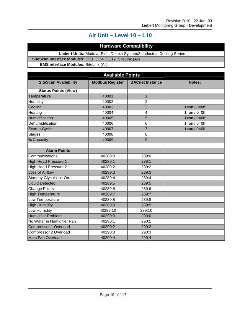
This document contains a dedicated sheet for each Liebert Unit and associated controller. The title of each chart contains the name of the Liebert Controller used such as L00 for a Level-0 Air unit or PMP for a Power Monitoring Panel for Power Center.
The first section, Compatible Hardware, indicates the equipment associated with this particular controller as follows: Liebert Units Indicates the Environmental, Power, UPS or Monitoring Module by model name that
uses this controller. SiteScan Interface Modules
Indicates which SiteScan Hardware Modules can be used with the controller. Take Special note of this box when adding new units to an existing SiteScan system, as some new controllers are only compatible with the new hardware (SiteLink).
BMS interface Modules Indicates which SiteScan Hardware Modules can be used with the controller for interfacing with a third part using BACnet or Modbus protocol.
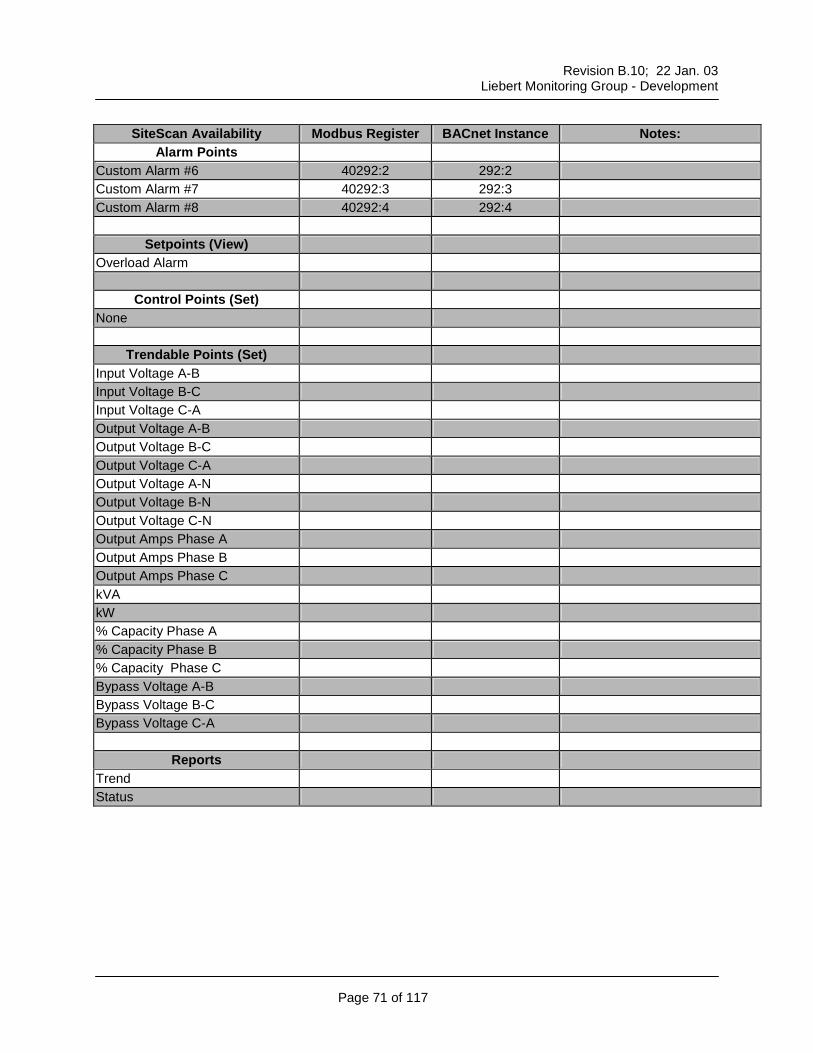
The next section, Available Points, contains six categories providing the following information: Status Points (View) Status Information for the listed points that will be presented in SiteScan Alarm Points Alarms that are available to SiteScan Setpoints (View) Current settings of controllable Setpoints available to SiteScan Control Points (Set) Setpoints that can be changed with SiteScan Trendable Points (Set) Points that can be graphically trended within the SiteScan software Reports Reports that can be triggered within the SiteScan software
Revision B.10; 22 Jan. 03
Liebert Monitoring Group - Development
Page 6 of 117
Liebert Unit ID Chart 3-Letter
ID Environmental Products 3-Letter
ID UPS Products
L00 Level 00, Level 1 SMS Single Module Series UPS - S300, S500, S600 (Prior to 1/98)
L10 Level 2, Level 3, and Level 10 SM3 Single Module Series 30x (latest version)
LAM Level 15 and Level AM/AG, HiMod (LNA)
SM4 Single Module Series 600 - Extended Protocol (1/98 or later)
LSM Level SM and Level 0 w/ On/Off Control
US3 UPStation S3 UPS
L0B Small Systems Controller MMS Multi Module Series 500-600 UPS (Prior to 1/98)
MM2 Small Systems Controller - Mini Mate II, DataMate
MM4 Multi Module Series 600 UPS - Extended Protocol (1/98 or later)
C10 Atlas Air Environmental Control (LECS15)
SCC System Control Cabinet Series 500-600 (Prior to 1/98)
CSE Chiller w/ Econocoil SC4 System Control Cabinet Series 600- Extended Protocol (1/98 or later)
CSU Chiller SSM Single Module Series UPS - SICE 7200 & HiPulse
SMM Multi Module Series UPS - SICE 7200 & HiPulse
Static Switch PDU SSC System Control Cabinet - SICE 7200 EDS Static Switch PDU (Single Output
Breaker, Prior to 1/99) IMP NPower (S300 Replacement)
PMP Precision Power & Datawaves w/ PMP (latest LCD display)
Miscellaneous VCF All Voltage-Current-Frequency Panels (Old Red LED Display)
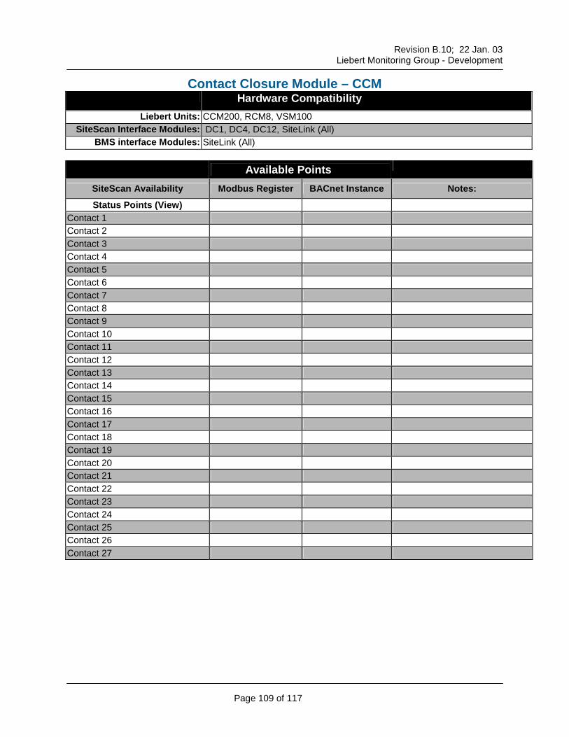
CCM All IGM Contact Modules CM200 / RCM8 / VSM
VCM All Voltage-Current Monitoring Panels (Old Red LED Display)
RAC Remote Autochangeover Module - RAC2-8
PM2 Precision Power & Datawaves w/ PMP (latest LCD display and extended protocol EPROM version 3.290.0, manufactured and shipped after 4/99)
THM Temperature / Humidity Module WDU Liquid Detection LDS750 or LDS1000
Revision B.10; 22 Jan. 03
Liebert Monitoring Group - Development
Page 7 of 117
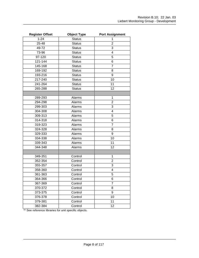
Open Communications Default Mapping for Modbus & BACnet Objects
This model represents the standard configuration for a Liebert Sitelink-12 module. Consecutive register / object mapping is utilized, regardless of the SiteLink-12 population. All ports that do not have a Liebert IGM attached will be assigned "null values" (or zero's) for their corresponding registers. The default “slave ID” or “Device ID” follows the CMnet address of the unit. The address can be visually checked by looking at the address dip-switch or rotary switch settings. However, the address can be changed in software to suit specific needs.
How to use this table:
The unit or model specific reference sheets assumes that the desired unit is attached to port 1 of the SiteLink module. If the desired unit is attached to a different port, the table below indicates the starting register or object number for the unit.
For example: The register for “temperature” for a L00 type unit attached to port 1 is identified as 40001. If an additional L00 type unit were attached to port 2, the “temperature” value would be located in register 40025. The same type unit attached to port 3 = 40049…etc.
Modbus Notes:
• Modbus Registers start at 40001.
• All registers are unsigned integers.
BACnet Notes:
• BACnet Objects start at 1.
• All “Status” and “Alarm” objects are “AI’s” (analog inputs).
• The “Control” objects are “AO’s” (analog outputs)
Revision B.10; 22 Jan. 03
Liebert Monitoring Group - Development
Page 8 of 117
Register Offset Object Type Port Assignment 1-24 Status 1 25-48 Status 2 49-72 Status 3 73-96 Status 4
97-120 Status 5 121-144 Status 6 145-168 Status 7 169-192 Status 8 193-216 Status 9 217-240 Status 10 241-264 Status 11 265-288 Status 12
349-351 Control 1 352-354 Control 2 355-357 Control 3 358-360 Control 4 361-363 Control 5 364-366 Control 6 367-369 Control 7 370-372 Control 8 373-375 Control 9 376-378 Control 10 379-381 Control 11 382-384 Control 12
** See reference libraries for unit specific objects.
Revision B.10; 22 Jan. 03
Liebert Monitoring Group - Development
Page 9 of 117
Modbus Communications Connectivity to SiteLink modules using Modbus
This design specification describes the Modbus communications protocol as supported by the SiteLink
module. It includes information on how to pass information to and from the SiteLink module via Modbus.
It is also intended to help facilitate answering questions regarding supported types, frame format, function
code support etc.
Implementation Basics Protocol controls the language structure or message format between devices in other words, the rules for
communication. The rules for communication include how master and slave devices initiate
communications, as well as unit identification, message handling and error checking. Modbus protocol
simply refers to the control of the query and response cycles between master and slave devices.
The SiteLink module is configured to act as a slave device on a common network. The common network
can be point-to-point over EIA-232, where one master communicates to one slave device or in a multi-
drop configuration over EIA-485, where multiple slaves reside on a common wire or loop.
Transmission Format The SiteLink module supports both Modbus RTU (Remote Terminal Unit) and ASCII (American Standard
Code for Information Interchange) transmission modes. The SiteLink module has a choice of
transmission medium, baud rate, character parity and number of stop bits. See chart below.
Physical Port
Transmission Mode
Baud Rate Data Bits Parity Bits Stop Bits Default
EIA-232 – DB9 DCE
RTU 9600 8 None 1 Yes
EIA-232 – DB9 DCE
ASCII 1200 – 38.4kbd
(19.2kbd omit)
Configurable Configurable Configurable No
EIA-485 – 2 or 4 wire
RTU or ASCII 1200 – 38.4kbd
(19.2kbd omit)
Configurable Configurable Configurable No
Revision B.10; 22 Jan. 03
Liebert Monitoring Group - Development
Page 10 of 117
Modbus Packet Format Each Modbus packet consists of the following fields:
• Device Address
• Function Code
• Data Field(s)
• Error Check Field
Device Address: The address field immediately follows the beginning of the frame and consists of 8-bits (RTU) or 2
characters (ASCII). These bits indicate the user assigned address of the slave device that is to receive
the message sent by the attached master device.
Each slave must be assigned a unique address and only the addressed slave will respond to a query that
contains its address.
Function Code: The function code field tells the addressed slaves what function to perform. Function codes are
specifically designed invoke a specific action by the slave device. The function code range is from 1 to
127. However, the SiteLink module primarily uses Function Code 3 (Read Holding Registers),
Function Code 6 (Preset Single Register) and Function Code 16 (Preset Multiple Registers). Data Field(s):
The data field varies in length depending on whether the message is a request or a response to a packet.
This field typically contains information required by the slave device to perform the command specified or
to pass back data to the master device.
Error Check Field: The Error Check Field consists of a 16-bit (2 byte) Cyclical Redundancy Check (CRC16). It allows the
receiving device to detect a packet that has been corrupted with transmission errors.
Revision B.10; 22 Jan. 03
Liebert Monitoring Group - Development
Page 11 of 117
RTU Framing The example below shows a typical Q/R from a SiteLink module. In common terms, the master device initiates a query asking slave device 2 for holding registers starting at holding register 40051 (decimal 50) and including next 2 Registers (3 total).
Query Sample Slave
Address Function
Code Starting Register “Hi Byte”
Starting Register
“Lo Byte”
Number of Registers “Hi Byte”
Number of Registers “Lo Byte”
CRC16
“Hi Byte”
CRC16
“Lo Byte”
02 03 00 32 00 03 E5 FA
Response Sample Slave
Address Function
Code Count:
Bytes of Data
Register 40051 Data Hi Lo
Register 40052 Data Hi Lo
Register 40053 Data Hi Lo
CRC16
“Hi Byte
CRC16
“Lo Byte”
02 03 6 01 58 00 FA 00 54 1B 0D
Slave address 2 responds to Function Code 3 with 6 bytes of hexadecimal data and ends with CRC16 checksum.
ASCII Framing: Framing in ASCII transmission mode is accomplished by the use of the unique colon (:) to indicate the beginning of the frame and a carriage return (CR) line feed (LF) to delineate the end of the frame. The line feed also serves as a synchronizing character which indicates that the transmitting station is ready to receive an immediate reply.
ASCII Example Frame Start
Slave Address
Function Code
Data Error Check
End of Frame
CR
Ready for Data LF
: 2 Char
16-bits
2 Char
16-bits
N x 4 Char
N x 16-bits
B3 0D 0A
Char = Character: 1 Character = 7 data bits, 1 start bit, 1 or 2 stop bits and 1 parity bit (optional)
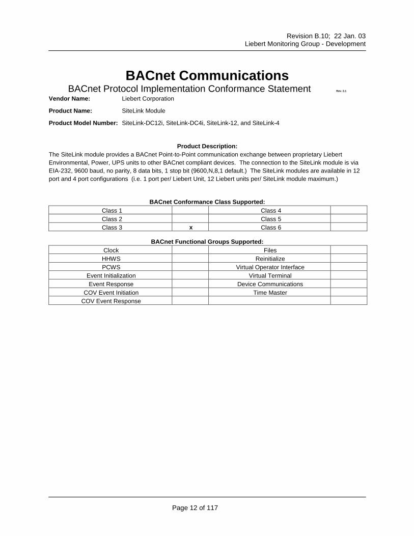
Product Model Number: SiteLink-DC12i, SiteLink-DC4i, SiteLink-12, and SiteLink-4
Product Description: The SiteLink module provides a BACnet Point-to-Point communication exchange between proprietary Liebert Environmental, Power, UPS units to other BACnet compliant devices. The connection to the SiteLink module is via EIA-232, 9600 baud, no parity, 8 data bits, 1 stop bit (9600,N,8,1 default.) The SiteLink modules are available in 12 port and 4 port configurations (i.e. 1 port per/ Liebert Unit, 12 Liebert units per/ SiteLink module maximum.)
BACnet Conformance Class Supported: Class 1 Class 4 Class 2 Class 5 Class 3 x Class 6
Alarm Points Communications 40289:0 289:0 High Head Pressure 1 40289:1 289:1 High Head Pressure 2 40289:2 289:2 Loss of Airflow 40289:3 289:3 Liquid Detected 40289:4 289:4 Change Filters 40289:5 289:5 High Temperature 40289:6 289:6 Low Temperature 40289:7 289:7 High Humidity 40289:8 289:8 Low Humidity 40289:9 289:9 Local Alarm 40289:10 289:10
Setpoints (View) Temperature Setpoint 40010 10 Temperature Tolerance 40011 11 Humidity Setpoint 40012 12 Humidity Tolerance 40013 13
Control Points (Set) Temperature Setpoint 40350 350 Temperature Tolerance 40350 350 Multiply desired value by 1000 Humidity Setpoint 40351 351 Humidity Tolerance 40351 351 Multiply desired value by 1000
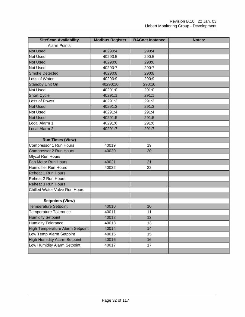
Alarm Points Communications 40289:0 289:0 High Head Pressure 1 40289:1 289:1 High Head Pressure 2 40289:2 289:2 Loss of Airflow 40289:3 289:3 Standby Glycol Unit On 40289:4 289:4 Liquid Detected 40289:5 289:5 Change Filters 40289:6 289:6 High Temperature 40289:7 289:7 Low Temperature 40289:8 289:8 High Humidity 40289:9 289:9 Low Humidity 40289:10 289:10 Humidifier Problem 40290:0 290:0 No Water in Humidifier Pan 40290:1 290:1 Compressor 1 Overload 40290:2 290:2 Compressor 2 Overload 40290:3 290:3 Main Fan Overload 40290:4 290:4
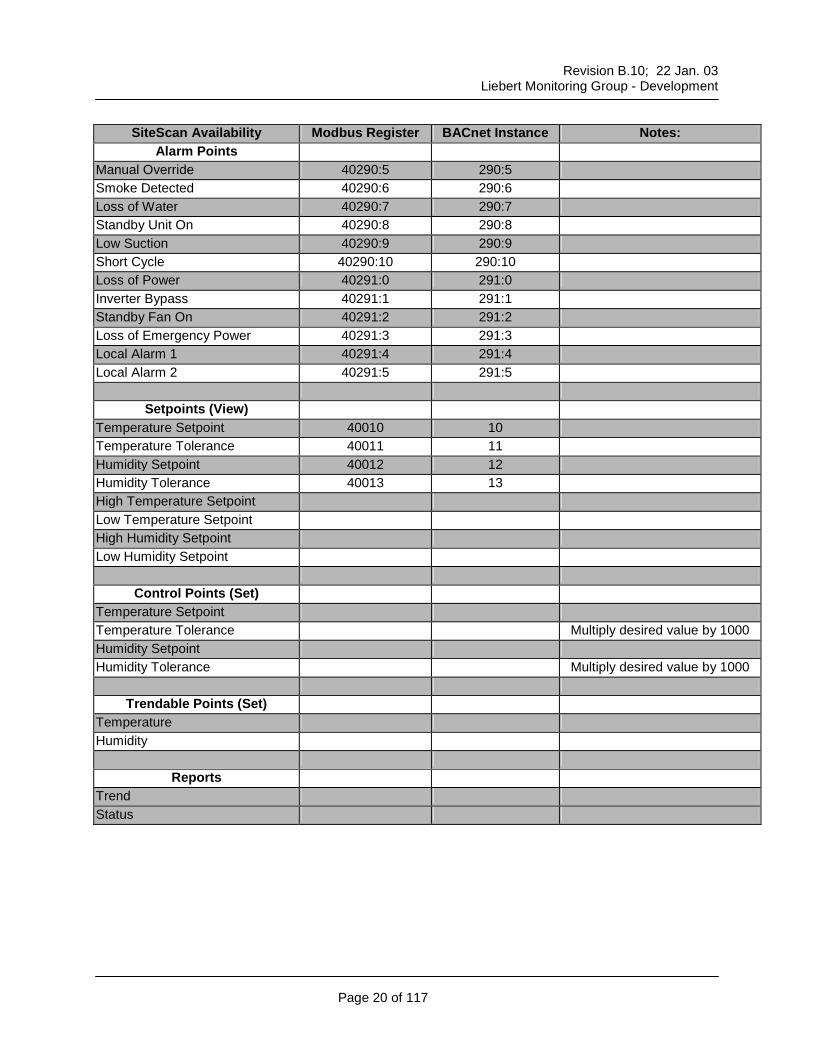
Alarm Points Manual Override 40290:5 290:5 Smoke Detected 40290:6 290:6 Loss of Water 40290:7 290:7 Standby Unit On 40290:8 290:8 Low Suction 40290:9 290:9 Short Cycle 40290:10 290:10 Loss of Power 40291:0 291:0 Inverter Bypass 40291:1 291:1 Standby Fan On 40291:2 291:2 Loss of Emergency Power 40291:3 291:3 Local Alarm 1 40291:4 291:4 Local Alarm 2 40291:5 291:5
Setpoints (View) Temperature Setpoint 40010 10 Temperature Tolerance 40011 11 Humidity Setpoint 40012 12 Humidity Tolerance 40013 13 High Temperature Setpoint Low Temperature Setpoint High Humidity Setpoint Low Humidity Setpoint
Control Points (Set) Temperature Setpoint Temperature Tolerance Multiply desired value by 1000 Humidity Setpoint Humidity Tolerance Multiply desired value by 1000
Trendable Points (Set) Temperature Humidity
Reports Trend Status
Revision B.10; 22 Jan. 03
Liebert Monitoring Group - Development
Page 21 of 117
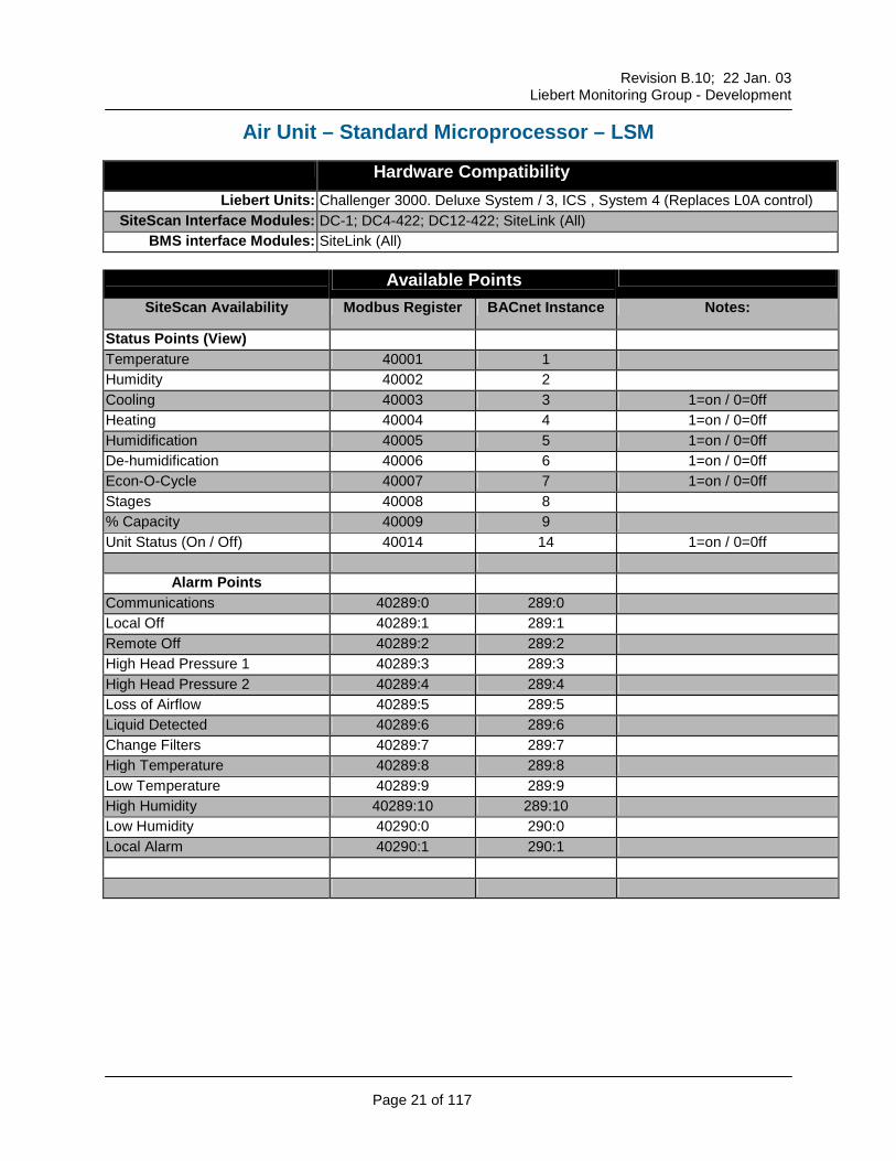
Air Unit – Standard Microprocessor – LSM
Hardware Compatibility Liebert Units: Challenger 3000. Deluxe System / 3, ICS , System 4 (Replaces L0A control)
Alarm Points Communications 40289:0 289:0 Local Off 40289:1 289:1 Remote Off 40289:2 289:2 High Head Pressure 1 40289:3 289:3 High Head Pressure 2 40289:4 289:4 Loss of Airflow 40289:5 289:5 Liquid Detected 40289:6 289:6 Change Filters 40289:7 289:7 High Temperature 40289:8 289:8 Low Temperature 40289:9 289:9 High Humidity 40289:10 289:10 Low Humidity 40290:0 290:0 Local Alarm 40290:1 290:1
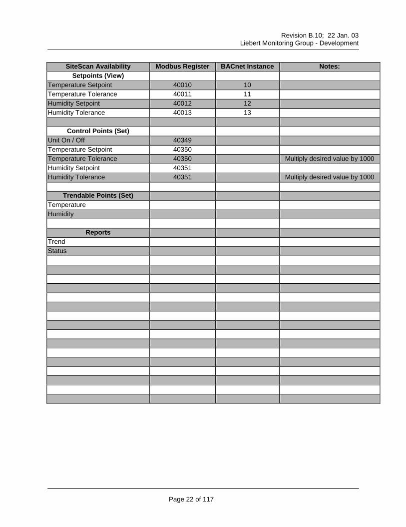
Setpoints (View) Temperature Setpoint 40010 10 Temperature Tolerance 40011 11 Humidity Setpoint 40012 12 Humidity Tolerance 40013 13
Control Points (Set) Unit On / Off 40349 Temperature Setpoint 40350 Temperature Tolerance 40350 Multiply desired value by 1000 Humidity Setpoint 40351 Humidity Tolerance 40351 Multiply desired value by 1000
Trendable Points (Set)
Temperature Humidity
Reports Trend Status
Revision B.10; 22 Jan. 03
Liebert Monitoring Group - Development
Page 23 of 117
Air Unit – Advanced Microprocessor – LAM
Hardware Compatibility Liebert Units: Challenger 3000. Deluxe System / 3, ICS , System 4 (Replaces L15 & L1A)
Alarm Points Communications 40289:0 289:0 Local Off 40289:1 289:1 Remote Off 40289:2 289:2 High Head Pressure 1 40289:3 289:3 High Head Pressure 2 40289:4 289:4 Loss of Airflow 40289:5 289:5 Standby Glycol Unit On 40289:6 289:6 Liquid Detected 40289:7 289:7 Change Filters 40289:8 289:8 High Temperature 40289:9 289:9 Low Temperature 40289:10 289:10 High Humidity 40290:0 290:0 Low Humidity 40290:1 290:1 Humidifier Problem 40290:2 290:2 No Water in Humidifier Pan 40290:3 290:3
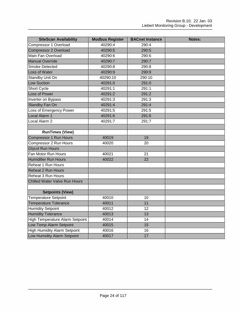
Compressor 1 Overload 40290:4 290:4 Compressor 2 Overload 40290:5 290:5 Main Fan Overload 40290:6 290:6 Manual Override 40290:7 290:7 Smoke Detected 40290:8 290:8 Loss of Water 40290:9 290:9 Standby Unit On 40290:10 290:10 Low Suction 40291:0 291:0 Short Cycle 40291:1 291:1 Loss of Power 40291:2 291:2 Inverter on Bypass 40291:3 291:3 Standby Fan On 40291:4 291:4 Loss of Emergency Power 40291:5 291:5 Local Alarm 1 40291:6 291:6 Local Alarm 2 40291:7 291:7
RunTimes (View) Compressor 1 Run Hours 40019 19 Compressor 2 Run Hours 40020 20 Glycol Run Hours Fan Motor Run Hours 40021 21 Humidifier Run Hours 40022 22 Reheat 1 Run Hours Reheat 2 Run Hours Reheat 3 Run Hours Chilled Water Valve Run Hours
Setpoints (View) Temperature Setpoint 40010 10 Temperature Tolerance 40011 11 Humidity Setpoint 40012 12 Humidity Tolerance 40013 13 High Temperature Alarm Setpoint 40014 14 Low Temp Alarm Setpoint 40015 15 High Humidity Alarm Setpoint 40016 16 Low Humidity Alarm Setpoint 40017 17
Revision B.10; 22 Jan. 03
Liebert Monitoring Group - Development
Page 25 of 117
SiteScan Availability Modbus Register BACnet Instance Notes: Control Points (Set)
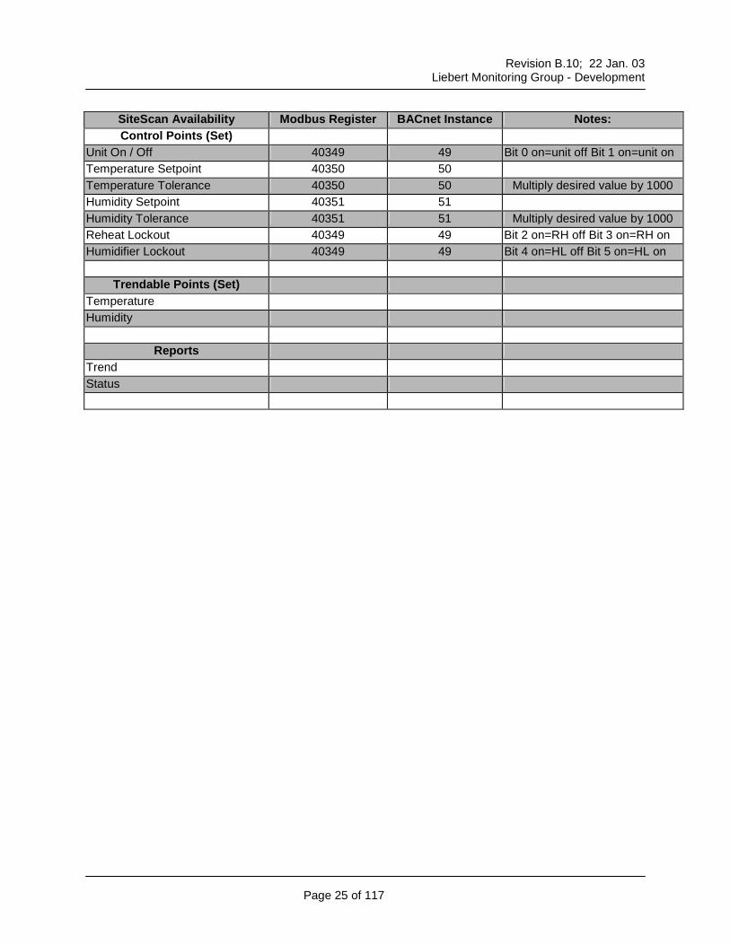
Unit On / Off 40349 49 Bit 0 on=unit off Bit 1 on=unit on Temperature Setpoint 40350 50 Temperature Tolerance 40350 50 Multiply desired value by 1000 Humidity Setpoint 40351 51 Humidity Tolerance 40351 51 Multiply desired value by 1000 Reheat Lockout 40349 49 Bit 2 on=RH off Bit 3 on=RH on Humidifier Lockout 40349 49 Bit 4 on=HL off Bit 5 on=HL on
Trendable Points (Set) Temperature Humidity
Reports Trend Status
Revision B.10; 22 Jan. 03
Liebert Monitoring Group - Development
Page 26 of 117
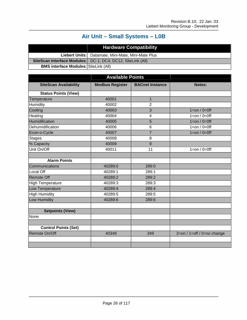
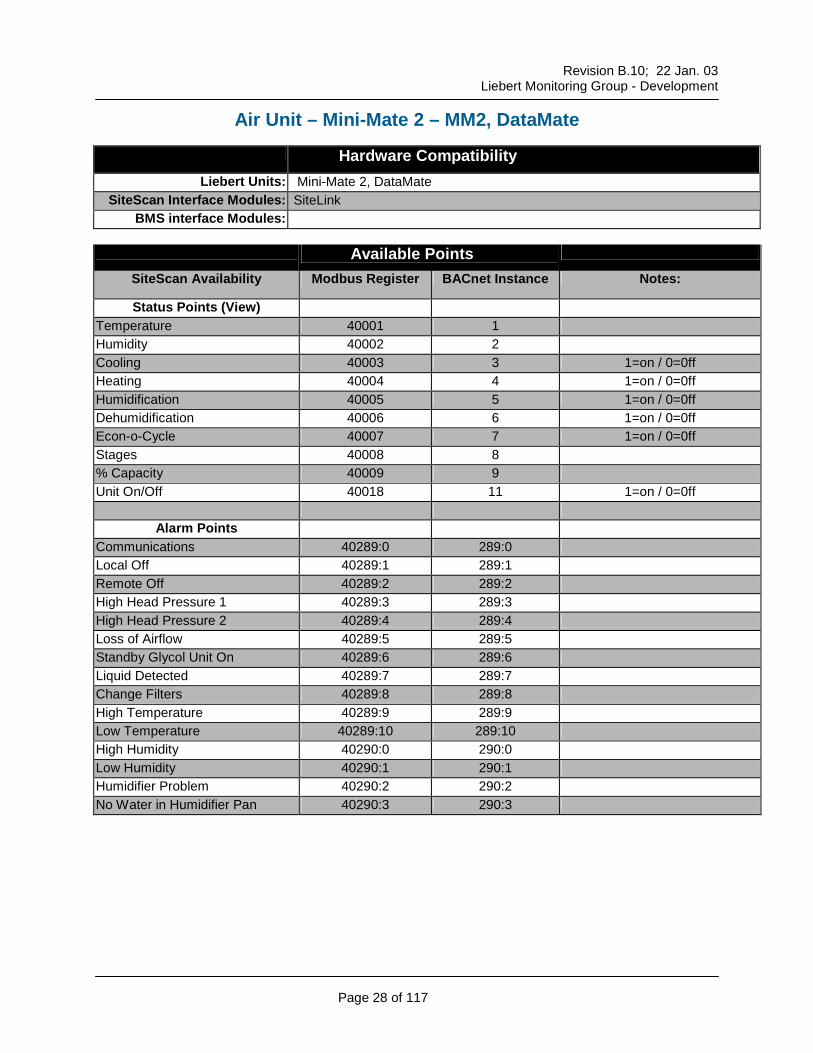
Air Unit – Small Systems – L0B
Hardware Compatibility Liebert Units: Datamate, Mini-Mate, Mini-Mate Plus
Alarm Points Communications 40289:0 289:0 Local Off 40289:1 289:1 Remote Off 40289:2 289:2 High Temperature 40289:3 289:3 Low Temperature 40289:4 289:4 High Humidity 40289:5 289:5 Low Humidity 40289:6 289:6
Alarm Points Communications 40289:0 289:0 Local Off 40289:1 289:1 Remote Off 40289:2 289:2 High Head Pressure 1 40289:3 289:3 High Head Pressure 2 40289:4 289:4 Loss of Airflow 40289:5 289:5 Standby Glycol Unit On 40289:6 289:6 Liquid Detected 40289:7 289:7 Change Filters 40289:8 289:8 High Temperature 40289:9 289:9 Low Temperature 40289:10 289:10 High Humidity 40290:0 290:0 Low Humidity 40290:1 290:1 Humidifier Problem 40290:2 290:2 No Water in Humidifier Pan 40290:3 290:3
Alarm Points Compressor 1 Overload 40290:4 290:4 Compressor 2 Overload 40290:5 290:5 Main Fan Overload 40290:6 290:6 Manual Override 40290:7 290:7 Smoke Detected 40290:8 290:8 Loss of Water 40290:9 290:9 Standby Unit On 40290:10 290:10 Low Suction 40291:0 291:0 Short Cycle 40291:1 291:1 Loss of Power 40291:2 291:2 Inverter Bypass 40291:3 291:3 Standby Fan On 40291:4 291:4 Loss of Emergency Power 40291:5 291:5 Local Alarm 1 40291:6 291:6 Local Alarm 2 40291:7 291:7
Setpoints (View) Temperature Setpoint 40010 10 Temperature Tolerance 40011 11 Humidity Setpoint 40012 12 Humidity Tolerance 40013 13 High Temperature Alarm Setpoint 40014 14 Low Temperature Alarm Setpoint 40015 15 High Humidity Alarm Setpoint 40016 16 Low Humidity Alarm Setpoint 40017 17
Control Points (Set)
Remote On/Off 40349 49 2=on / 1=off / 0=no change Temperature Setpoint 40350 50 Temperature Tolerance 40350 50 Multiply desired value by 1000 Humidity Setpoint 40351 51 Humidity Tolerance 40351 51 Multiply desired value by 1000
Alarm Points Communications 40289:0 289:0 Local Off 40289:1 289:1 Remote Off 40289:2 289:2 High Head Pressure 1 40289:3 289:3 High Head Pressure 2 40289:4 289:4 Loss of Airflow 40289:5 289:5 Standby Glycol Unit On 40289:6 289:6 Not Used 40289:7 289:7 Change Filters 40289:8 289:8 High Temperature 40289:9 289:9 Low Temperature 40289:10 289:10 High Humidity 40290:0 290:0 Low Humidity 40290:1 290:1 Humidifier Problem 40290:2 290:2 Not Used 40290:3 290:3
Alarm Points Not Used 40290:4 290:4 Not Used 40290:5 290:5 Not Used 40290:6 290:6 Not Used 40290:7 290:7 Smoke Detected 40290:8 290:8 Loss of Water 40290:9 290:9 Standby Unit On 40290:10 290:10 Not Used 40291:0 291:0 Short Cycle 40291:1 291:1 Loss of Power 40291:2 291:2 Not Used 40291:3 291:3 Not Used 40291:4 291:4 Not Used 40291:5 291:5 Local Alarm 1 40291:6 291:6 Local Alarm 2 40291:7 291:7
Run Times (View)
Compressor 1 Run Hours 40019 19 Compressor 2 Run Hours 40020 20 Glycol Run Hours Fan Motor Run Hours 40021 21 Humidifier Run Hours 40022 22 Reheat 1 Run Hours Reheat 2 Run Hours Reheat 3 Run Hours Chilled Water Valve Run Hours
Setpoints (View)
Temperature Setpoint 40010 10 Temperature Tolerance 40011 11 Humidity Setpoint 40012 12 Humidity Tolerance 40013 13 High Temperature Alarm Setpoint 40014 14 Low Temp Alarm Setpoint 40015 15 High Humidity Alarm Setpoint 40016 16 Low Humidity Alarm Setpoint 40017 17
Revision B.10; 22 Jan. 03
Liebert Monitoring Group - Development
Page 33 of 117
SiteScan Availability Modbus Register BACnet Instance Notes: Control Points (Set)
Unit On / Off 40349 49 Bit 0 on=unit off Bit 1 on=unit on Temperature Setpoint 40350 50 Temperature Tolerance 40350 50 Multiply desired value by 1000 Humidity Setpoint 40351 51 Humidity Tolerance 40351 51 Multiply desired value by 1000 Reheat Lockout 40349 49 Bit 2 on=RH off Bit 3 on=RH on Humidifier Lockout 40349 49 Bit 4 on=HL off Bit 5 on=HL on
Alarm Points Communications 40289:0 289:0 Module 1 High Head Pressure 40289:1 289:1 Module 2 High Head Pressure 40289:2 289:2 Module 3 High Head Pressure 40289:3 289:3 Module 1 No Water Flow 40289:4 289:4 Module 2 No Water Flow 40289:5 289:5 Module 3 No Water Flow 40289:6 289:6 Module 1 High Water Temp. 40289:7 289:7 Module 2 High Water Temp. 40289:8 289:8 Module 3 High Water Temp. 40289:9 289:9 Module 1 Low Water Temp. 40289:10 289:10 Module 2 Low Water Temp. 40290:0 290:0 Module 3 Low Water Temp. 40290:1 290:1 Module 1 No Power 40290:2 290:2 Module 2 No Power 40290:3 290:3
Communications 40289:0 289:0 Module 1 High Head Pressure 40289:1 289:1 Module 2 High Head Pressure 40289:2 289:2 Module 3 High Head Pressure 40289:3 289:3 Module 1 No Water Flow 40289:4 289:4 Module 2 No Water Flow 40289:5 289:5 Module 3 No Water Flow 40289:6 289:6 Module 1 High Water Temp. 40289:7 289:7 Module 2 High Water Temp. 40289:8 289:8 Module 3 High Water Temp. 40289:9 289:9 Module 1 Low Water Temp. 40289:10 289:10
Revision B.10; 22 Jan. 03
Liebert Monitoring Group - Development
Page 40 of 117
SiteScan Availability Notes:
Alarm Points Module 2 Low Water Temp. 40290:0 290:0 Module 3 Low Water Temp. 40290:1 290:1 Module 1 No Power 40290:2 290:2 Module 2 No Power 40290:3 290:3 Module 3 No Power 40290:4 290:4
Setpoints (Set) None
Control Points (Set)
None
Trendable Points (Set) None
Reports
Status
Revision B.10; 22 Jan. 03
Liebert Monitoring Group - Development
Page 41 of 117
Air Unit - Hiross Microface Hardware Compatibility
BMS interface Modules: Liebert Hiross Hirolink Available Points
SiteScan Availability Modbus Register BACnet Instance Notes: Status Points (View)
Unit On Off Heater Working Hours Humidifier Working Hours Compressor 1 Working Hours Conditioner Working Hours Low Humidity Warning High Humidity Warning Low Temperature Warning High Temperature Warning Humidity Proportional Band Temperature Proportional Band Room Humidity Setpoint Room Temperature Setpoint 1 Compressor 2 Working Hours Free-cooling Working Hours Cooling Ramp Status Dehumidification Status Electrical Heater 2 Status Electrical Heater 1 Status Compressor 1 Humidifier Current Room Humidity Room Temperature Status Compressor 2 Free-cooling Status
Alarm Points Compressor 1 High Pressure Compressor 1 Low Pressure High Chilled Water Low Chilled Water Flow Electrical Heaters Overheated Fan Failure Warning Fan Failure Alarm Clogged Filters Water Leakage Warning Water Leakage Alarm User Input 1 Triggered Warning User Input 1 Triggered Alarm Humidifier Failure Humidifier High Current Humidifier Failure Humidifier Failure Humidifier Cylinder Worn High Room Temperature Warning Low Room Temperature Warning High Room Humidity Warning Low Room Humidity Warning High Room Temperature Alarm Low Room Temperature Alarm High Room Humidity Alarm Low Room Humidity Alarm Cond. Working Hrs Exceeded Comp 1 Working Hours Exceeded Humd. Working Hours Exceeded PTC Sensor Failure Room Sensor Failure Warning Room Sensor Failure Alarm EEAP Sensor Failure Water Presence Sensor Failure Network Failure Out Of Memory Unit On Unit Off Sleep Mode Standby Mode Power On Unit Login Power Off Unit 1 Disconnected
Revision B.10; 22 Jan. 03
Liebert Monitoring Group - Development
Page 43 of 117
Unit 2 Disconnected Unit 3 Disconnected Unit 4 Disconnected Unit 5 Disconnected Unit 6 Disconnected Unit 7 Disconnected Unit 8 Disconnected Compressor 2 High Pressure Compressor 2 Low Pressure Comp 2 Working Hours Exceeded Outdoor Temperature Sensor Glycol Temperature Sensor Free-cooling Stopped For 1 Hour On-Off By Hiromatic Not Enabled
Alarm Points Smoke Alarm No Power (User Input) Power On (User Input) User Input 2 Triggered User Input 2 Triggered No Connection To Unit 1 Compressor 1 Motor Protection Compressor 2 Motor Protection Fire Alarm Out Of Memory Condenser 1 Fan Failure Condenser 2 Fan Failure Network Ping Subgroup-Id Not Unique Subgroup-Unit 1 Not Connected Subgroup-Unit 2 Not Connected Share Rm. Sensor Failure Warn Share Rm. Sensor Failure Alarm Share Outdoor Temp Sensor Share Glycol Temp Sensor Unit Synch (Short Reset) Humidifier High Temperature Humidifier Overflow
Setpoints (View) Room Temperature Setpoint 1 Temperature Proportional Band Room Humidity Setpoint Humidity Proportional Band High Temperature Alarm Setpoint Low Temp Alarm Setpoint High Humidity Alarm Setpoint Low Humidity Alarm Setpoint
Revision B.10; 22 Jan. 03
Liebert Monitoring Group - Development
Page 45 of 117
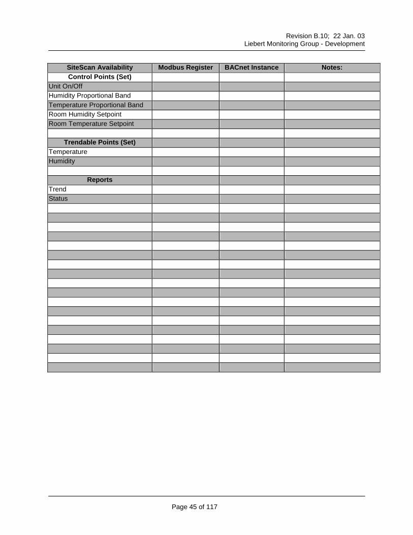
SiteScan Availability Modbus Register BACnet Instance Notes: Control Points (Set)
Unit On/Off Humidity Proportional Band Temperature Proportional Band Room Humidity Setpoint Room Temperature Setpoint
Trendable Points (Set) Temperature Humidity
Reports Trend Status
Revision B.10; 22 Jan. 03
Liebert Monitoring Group - Development
Page 46 of 117
Liebert Power Units
Revision B.10; 22 Jan. 03
Liebert Monitoring Group - Development
Page 47 of 117
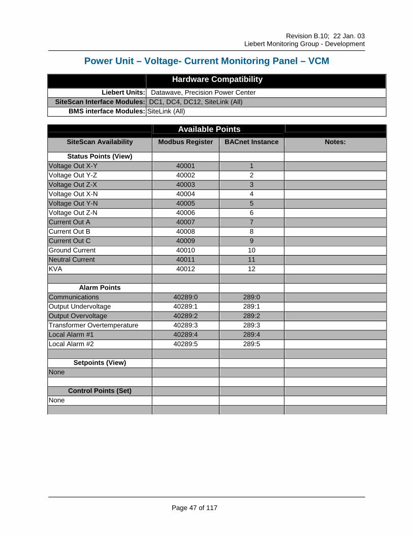
Power Unit – Voltage- Current Monitoring Panel – VCM
Hardware Compatibility Liebert Units: Datawave, Precision Power Center
Status Points (View) Voltage Out X-Y 40001 1 Voltage Out Y-Z 40002 2 Voltage Out Z-X 40003 3 Voltage Out X-N 40004 4 Voltage Out Y-N 40005 5 Voltage Out Z-N 40006 6 Current Out A 40007 7 Current Out B 40008 8 Current Out C 40009 9 Ground Current 40010 10 Neutral Current 40011 11 KVA 40012 12
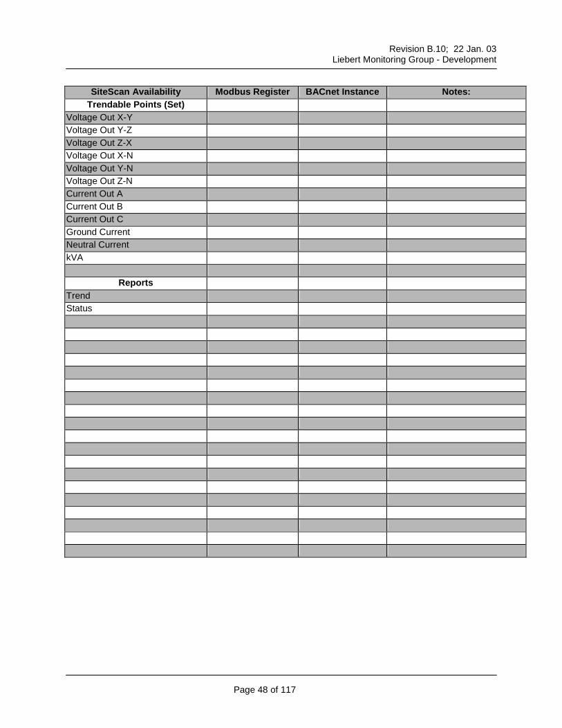
Trendable Points (Set) Voltage Out X-Y Voltage Out Y-Z Voltage Out Z-X Voltage Out X-N Voltage Out Y-N Voltage Out Z-N Current Out A Current Out B Current Out C Ground Current Neutral Current kVA
Reports Trend Status
Revision B.10; 22 Jan. 03
Liebert Monitoring Group - Development
Page 49 of 117
Power Unit – Power Monitoring Panel – PMP
Hardware Compatibility Liebert Units: Datawave, Precision Power Center
Status Points (View) Voltage In A-B 40001 1 Voltage In B-C 40002 2 Voltage In C-A 40003 3 Voltage Out A-B 40004 4 Voltage Out B-C 40005 5 Voltage Out C-A 40006 6 Voltage Out A-N 40007 7 Voltage Out B-N 40008 8 Voltage Out C-N 40009 9 Current Out A 40010 10 Current Out B 40011 11 Current Out C 40012 12 Ground Current 40013 13 Divide by 10 for correct value Neutral Current 40014 14 KVA 40015 15 KW 40016 16 Frequency 40017 17 Divide by 10 for correct value % Capacity A 40018 18 % Capacity B 40019 19 % Capacity C 40020 20
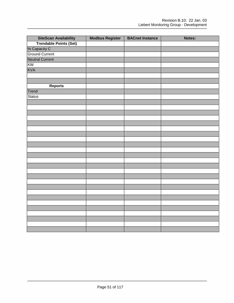
Voltage In A-B Voltage In B-C Voltage In C-A Voltage Out A-B Voltage Out B-C Voltage Out C-A Voltage In A-N Voltage In B-N Voltage In C-N Current Out A Current Out B Current Out C % Capacity A % Capacity B
SiteScan Availability Modbus Register BACnet Instance Notes: Status Points (View)
Voltage Out X-Y 40001 1 Voltage Out Y-Z 40002 2 Voltage Out Z-X 40003 3 Voltage Out X-N 40004 4 Voltage Out Y-N 40005 5 Voltage Out Z-N 40006 6 Current Out A 40007 7 Current Out B 40008 8 Current Out C 40009 9 Ground Current 40010 10 Neutral Current 40011 11 KVA 40012 12 Frequency 40013 13 Divide by 10 for correct value
Trendable Points (Set) Voltage Out X-Y Voltage Out Y-Z Voltage Out Z-X Voltage Out X-N Voltage Out Y-N Voltage Out Z-N Current Out A Current Out B Current Out C Ground Current Neutral Current kVA
Reports Trend Status
Revision B.10; 22 Jan. 03
Liebert Monitoring Group - Development
Page 54 of 117
Power Unit – Power Monitoring Panel (Ext. Protocol) – PM2
Hardware Compatibility Liebert Units: Datawave, Precision Power Center
Status Points (View) Voltage In X-Y 40001 1 Voltage In Y-Z 40002 2 Voltage In Z-X 40003 3 Voltage Out A-B 40004 4 Voltage Out B-C 40005 5 Voltage Out C-A 40006 6 Voltage Out A-N 40007 7 Voltage Out B-N 40008 8 Voltage Out C-N 40009 9 Current Out A 40010 10 Current Out B 40011 11 Current Out C 40012 12 Ground Current 40013 13 Divide by 10 for correct value Neutral Current 40014 14 KVA 40015 15 KW 40016 16 Frequency 40017 17 Divide by 10 for correct value % Capacity A 40018 18 % Capacity B 40019 19 % Capacity C 40020 20 Power Factor 40021 21 Divide by 100 for correct value Kilowatt Hours THD Voltage X THD Voltage Y THD Voltage Z THD Current X THD Current Y
Revision B.10; 22 Jan. 03
Liebert Monitoring Group - Development
Page 55 of 117
SiteScan Availability Modbus Register BACnet Instance Notes: Status Points (View)
THD Current Z K Factor Current X K Factor Current Y K Factor Current Z CREST Factor Current X CREST Factor Current Y CREST Factor Current Z
Trendable Points (Set) Voltage In A-B Voltage In B-C Voltage In C-A Voltage Out A-B Voltage Out B-C Voltage Out C-A Voltage In A-N Voltage In B-N Voltage In C-N Current Out A Current Out B Current Out C % Capacity A % Capacity B % Capacity C Ground Current Neutral Current KW KVA Power Factor THD Voltage X THD Voltage Y THD Voltage Z THD Current X THD Current Y THD Current Z K Factor Current X K Factor Current Y K Factor Current Z CREST Factor Current X CREST Factor Current Y CREST Factor Current Z
Reports Trend Status
Revision B.10; 22 Jan. 03
Liebert Monitoring Group - Development
Page 57 of 117
Power Unit – Static Transfer Switch PDU – EDS
Hardware Compatibility Liebert Units: Static Transfer Switch
SiteScan Availability Modbus Register BACnet Instance Notes: Status Points (View)
Transfer Count 40001 1 Preferred Source 40002 2 1=Source 1 / 0=Source 2 Load On Source 1 or Source 2 40003 3 1=Source 1 / 2=Source 2 Source 1 Voltage A-B 40004 4 Source 1 Voltage B-C 40005 5 Source 1 Voltage C-A 40006 6 Source 1 Current A 40007 7 Source 1 Current B 40008 8 Source 1 Current C 40009 9 Source 1 Frequency 40010 10 Divide by 10 for correct value Source 2 Voltage A-B 40011 11 Source 2 Voltage B-C 40012 12 Source 2 Voltage C-A 40013 13 Source 2 Current A 40014 14 Source 2 Current B 40015 15 Source 2 Current C 40016 16 Source 2 Frequency 40017 17 Divide by 10 for correct value KW 40018 18 KVA 40019 19 Auto Transfer Timer 40020 20 Nominal Voltage Deviation 40021 21 Phase Differential Limit 40022 22 Frequency Deviation 40023 23 Divide by 10 for correct value Auto Transfer Enabled 40024 24 1=Enabled / 0=Disabled
Trendable Points (Set) Source 1 Voltage A-B Source 1 Voltage B-C Source 1 Voltage C-A Source 1 Current A Source 1 Current B Source 1 Current C Source 2 Voltage A-B Source 2 Voltage B-C Source 2 Voltage C-A Source 2 Current A Source 2 Current B Source 2 Current C KW KVA
Reports Trend Status
Revision B.10; 22 Jan. 03
Liebert Monitoring Group - Development
Page 60 of 117
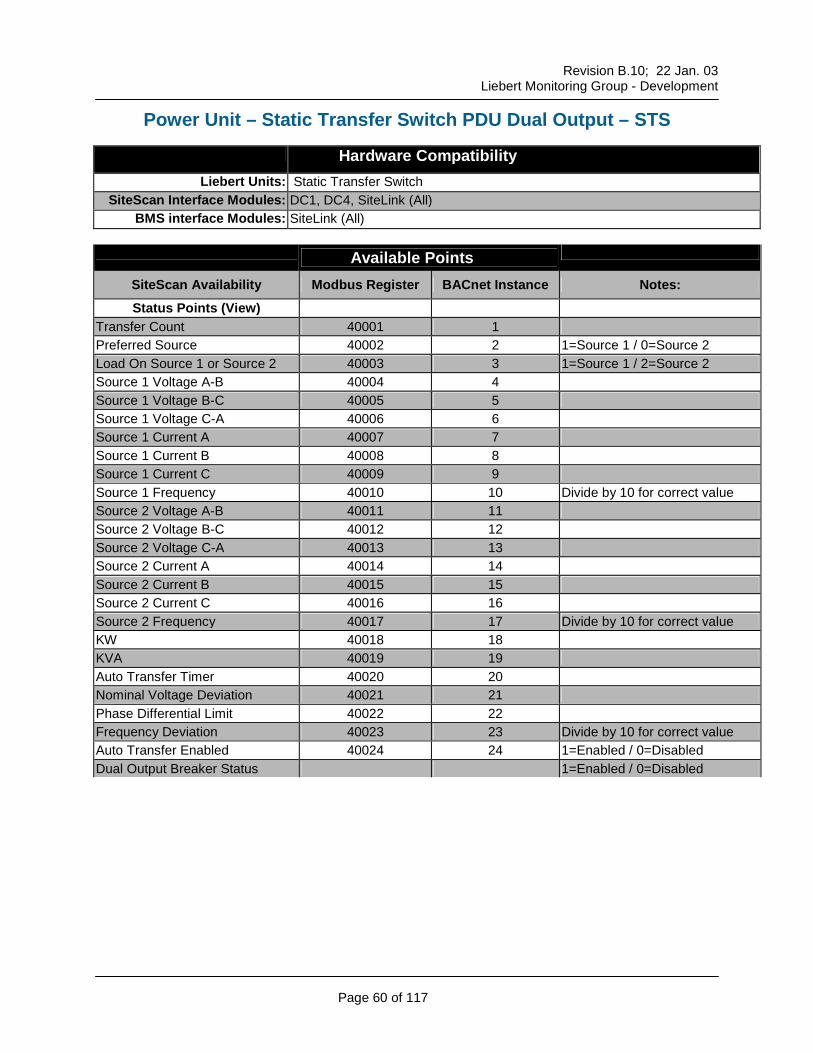
Power Unit – Static Transfer Switch PDU Dual Output – STS
Hardware Compatibility Liebert Units: Static Transfer Switch
SiteScan Availability Modbus Register BACnet Instance Notes: Status Points (View)
Transfer Count 40001 1 Preferred Source 40002 2 1=Source 1 / 0=Source 2 Load On Source 1 or Source 2 40003 3 1=Source 1 / 2=Source 2 Source 1 Voltage A-B 40004 4 Source 1 Voltage B-C 40005 5 Source 1 Voltage C-A 40006 6 Source 1 Current A 40007 7 Source 1 Current B 40008 8 Source 1 Current C 40009 9 Source 1 Frequency 40010 10 Divide by 10 for correct value Source 2 Voltage A-B 40011 11 Source 2 Voltage B-C 40012 12 Source 2 Voltage C-A 40013 13 Source 2 Current A 40014 14 Source 2 Current B 40015 15 Source 2 Current C 40016 16 Source 2 Frequency 40017 17 Divide by 10 for correct value KW 40018 18 KVA 40019 19 Auto Transfer Timer 40020 20 Nominal Voltage Deviation 40021 21 Phase Differential Limit 40022 22 Frequency Deviation 40023 23 Divide by 10 for correct value Auto Transfer Enabled 40024 24 1=Enabled / 0=Disabled Dual Output Breaker Status 1=Enabled / 0=Disabled
Setpoints (View) Auto Transfer Timer Nominal Voltage Deviation Phase Differential Limit Frequency Deviation Auto Transfer Enabled
Control Points (Set) None
Trendable Points (Set) Source 1 Voltage A-B Source 1 Voltage B-C Source 1 Voltage C-A Source 1 Current A Source 1 Current B Source 1 Current C Source 2 Voltage A-B Source 2 Voltage B-C Source 2 Voltage C-A Source 2 Current A Source 2 Current B Source 2 Current C KW KVA
Reports Trend Status
Revision B.10; 22 Jan. 03
Liebert Monitoring Group - Development
Page 63 of 117
Liebert UPS Units
Revision B.10; 22 Jan. 03
Liebert Monitoring Group - Development
Page 64 of 117
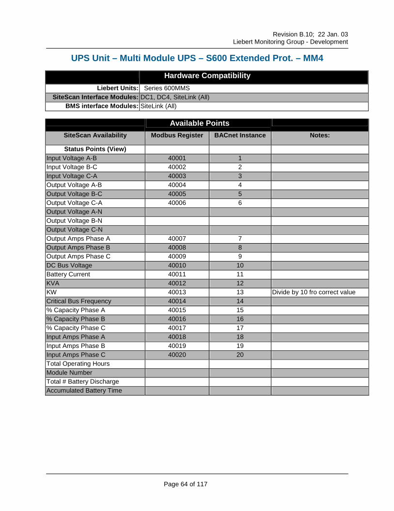
UPS Unit – Multi Module UPS – S600 Extended Prot. – MM4
Hardware Compatibility Liebert Units: Series 600MMS
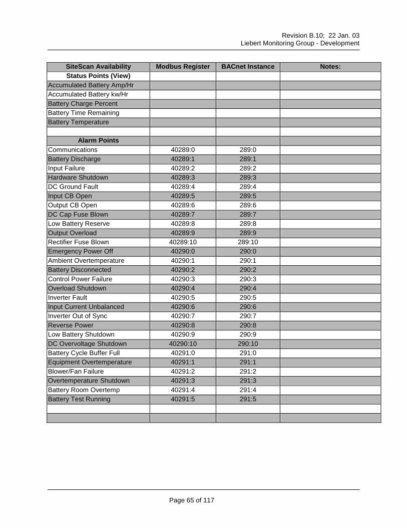
Status Points (View) Input Voltage A-B 40001 1 Input Voltage B-C 40002 2 Input Voltage C-A 40003 3 Output Voltage A-B 40004 4 Output Voltage B-C 40005 5 Output Voltage C-A 40006 6 Output Voltage A-N Output Voltage B-N Output Voltage C-N Output Amps Phase A 40007 7 Output Amps Phase B 40008 8 Output Amps Phase C 40009 9 DC Bus Voltage 40010 10 Battery Current 40011 11 KVA 40012 12 KW 40013 13 Divide by 10 fro correct value Critical Bus Frequency 40014 14 % Capacity Phase A 40015 15 % Capacity Phase B 40016 16 % Capacity Phase C 40017 17 Input Amps Phase A 40018 18 Input Amps Phase B 40019 19 Input Amps Phase C 40020 20 Total Operating Hours Module Number Total # Battery Discharge Accumulated Battery Time
Revision B.10; 22 Jan. 03
Liebert Monitoring Group - Development
Page 65 of 117
SiteScan Availability Modbus Register BACnet Instance Notes: Status Points (View)
Accumulated Battery Amp/Hr Accumulated Battery kw/Hr Battery Charge Percent Battery Time Remaining Battery Temperature
Alarm Points
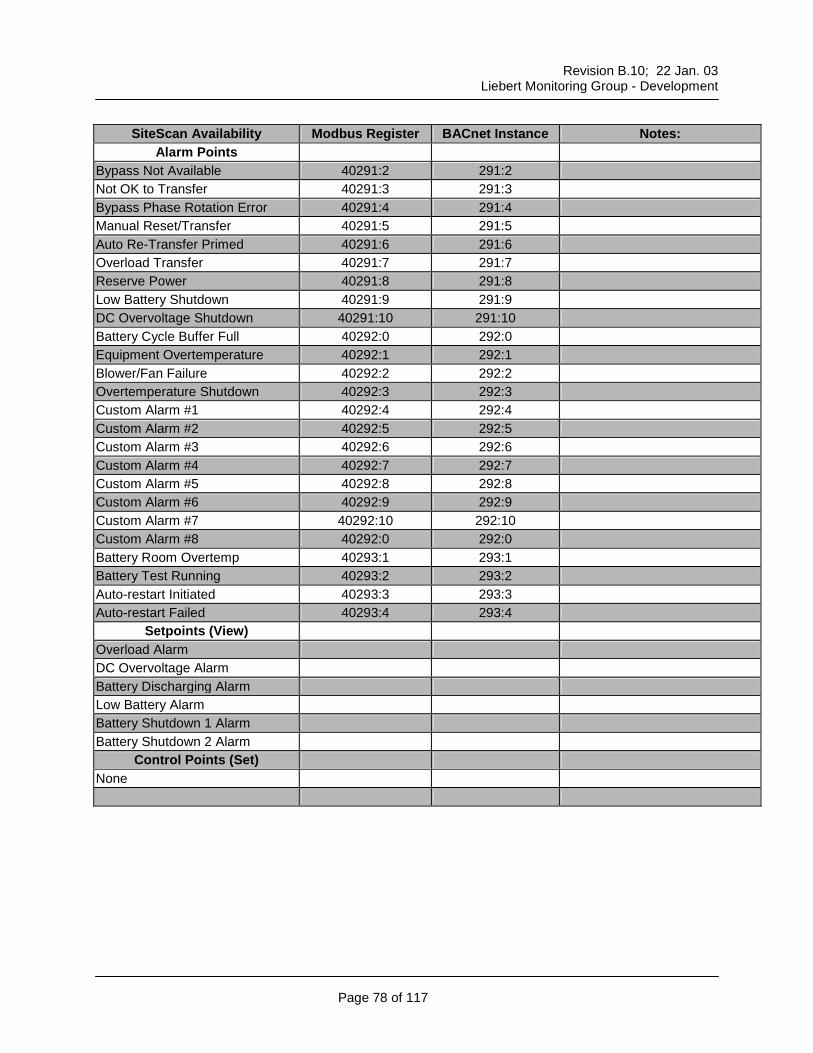
Communications 40289:0 289:0 Battery Discharge 40289:1 289:1 Input Failure 40289:2 289:2 Hardware Shutdown 40289:3 289:3 DC Ground Fault 40289:4 289:4 Input CB Open 40289:5 289:5 Output CB Open 40289:6 289:6 DC Cap Fuse Blown 40289:7 289:7 Low Battery Reserve 40289:8 289:8 Output Overload 40289:9 289:9 Rectifier Fuse Blown 40289:10 289:10 Emergency Power Off 40290:0 290:0 Ambient Overtemperature 40290:1 290:1 Battery Disconnected 40290:2 290:2 Control Power Failure 40290:3 290:3 Overload Shutdown 40290:4 290:4 Inverter Fault 40290:5 290:5 Input Current Unbalanced 40290:6 290:6 Inverter Out of Sync 40290:7 290:7 Reverse Power 40290:8 290:8 Low Battery Shutdown 40290:9 290:9 DC Overvoltage Shutdown 40290:10 290:10 Battery Cycle Buffer Full 40291:0 291:0 Equipment Overtemperature 40291:1 291:1 Blower/Fan Failure 40291:2 291:2 Overtemperature Shutdown 40291:3 291:3 Battery Room Overtemp 40291:4 291:4 Battery Test Running 40291:5 291:5
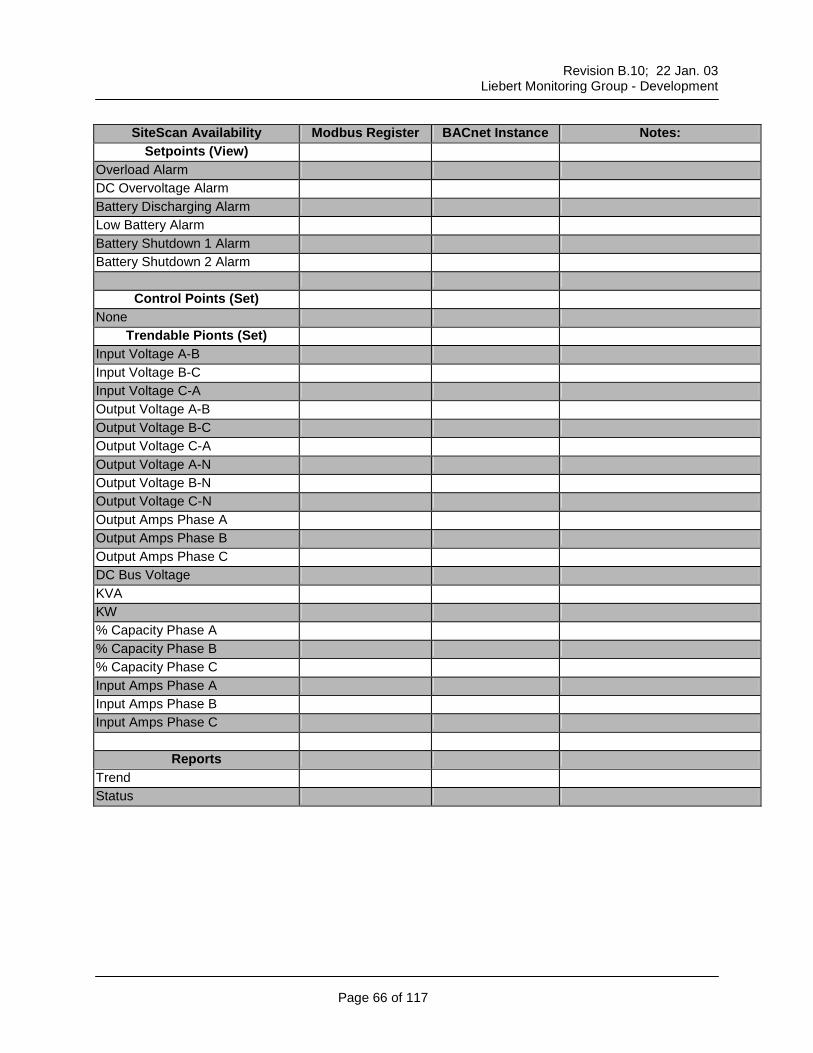
Input Voltage A-B Input Voltage B-C Input Voltage C-A Output Voltage A-B Output Voltage B-C Output Voltage C-A Output Voltage A-N Output Voltage B-N Output Voltage C-N Output Amps Phase A Output Amps Phase B Output Amps Phase C DC Bus Voltage KVA KW % Capacity Phase A % Capacity Phase B % Capacity Phase C Input Amps Phase A Input Amps Phase B Input Amps Phase C
Reports
Trend Status
Revision B.10; 22 Jan. 03
Liebert Monitoring Group - Development
Page 67 of 117
UPS Unit – Multi Module Series – MMS
Hardware Compatibility Liebert Units: Series 600MMS, Series 600T MS
Status Points (View) Voltage In A-B 40001 1 Voltage In B-C 40002 2 Voltage In C-A 40003 3 Voltage Out A-B 40004 4 Voltage Out B-C 40005 5 Voltage Out C-A 40006 6 Voltage Out A-N 40007 7 Voltage Out B-N 40008 8 Voltage Out C-N 40009 9 Current Out A 40010 10 Current Out B 40011 11 Current Out C 40012 12 DC Bus Voltage 40013 13 Battery Current 40014 14 KVA 40015 15 KW 40016 16 Frequency 40017 17 Divide by 10 for correct value % Capacity A 40018 18 % Capacity B 40019 19 % Capacity C 40020 20
Trendable Points (Set) Voltage In A-B Voltage In B-C Voltage In C-A Voltage Out A-B Voltage Out B-C Voltage Out C-A Voltage Out A-N Voltage Out B-N Voltage Out C-N Current Out A Current Out B Current Out C % Capacity A % Capacity B % Capacity C DC Bus Voltage DC Bus Current kW kVA
Reports Trend Status
Revision B.10; 22 Jan. 03
Liebert Monitoring Group - Development
Page 69 of 117
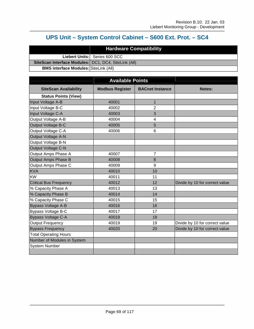
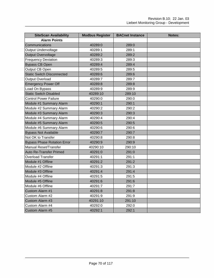
UPS Unit – System Control Cabinet – S600 Ext. Prot. – SC4
Hardware Compatibility Liebert Units: Series 600 SCC
SiteScan Availability Modbus Register BACnet Instance Notes: Status Points (View)
Input Voltage A-B 40001 1 Input Voltage B-C 40002 2 Input Voltage C-A 40003 3 Output Voltage A-B 40004 4 Output Voltage B-C 40005 5 Output Voltage C-A 40006 6 Output Voltage A-N Output Voltage B-N Output Voltage C-N Output Amps Phase A 40007 7 Output Amps Phase B 40008 8 Output Amps Phase C 40009 9 KVA 40010 10 KW 40011 11 Critical Bus Frequency 40012 12 Divide by 10 for correct value % Capacity Phase A 40013 13 % Capacity Phase B 40014 14 % Capacity Phase C 40015 15 Bypass Voltage A-B 40016 16 Bypass Voltage B-C 40017 17 Bypass Voltage C-A 40018 18 Output Frequency 40019 19 Divide by 10 for correct value Bypass Frequency 40020 20 Divide by 10 for correct value Total Operating Hours Number of Modules in System System Number
Trendable Points (Set) Input Voltage A-B Input Voltage B-C Input Voltage C-A Output Voltage A-B Output Voltage B-C Output Voltage C-A Output Voltage A-N Output Voltage B-N Output Voltage C-N Output Amps Phase A Output Amps Phase B Output Amps Phase C kVA kW % Capacity Phase A % Capacity Phase B % Capacity Phase C Bypass Voltage A-B Bypass Voltage B-C Bypass Voltage C-A
Reports
Trend Status
Revision B.10; 22 Jan. 03
Liebert Monitoring Group - Development
Page 72 of 117
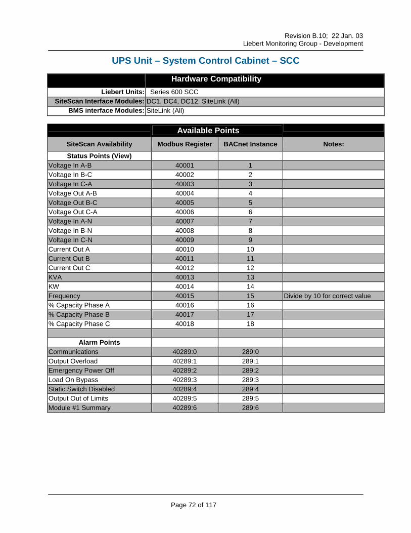
UPS Unit – System Control Cabinet – SCC
Hardware Compatibility Liebert Units: Series 600 SCC
SiteScan Availability Modbus Register BACnet Instance Notes: Status Points (View)
Voltage In A-B 40001 1 Voltage In B-C 40002 2 Voltage In C-A 40003 3 Voltage Out A-B 40004 4 Voltage Out B-C 40005 5 Voltage Out C-A 40006 6 Voltage In A-N 40007 7 Voltage In B-N 40008 8 Voltage In C-N 40009 9 Current Out A 40010 10 Current Out B 40011 11 Current Out C 40012 12 KVA 40013 13 KW 40014 14 Frequency 40015 15 Divide by 10 for correct value % Capacity Phase A 40016 16 % Capacity Phase B 40017 17 % Capacity Phase C 40018 18
Alarm Points Communications 40289:0 289:0 Output Overload 40289:1 289:1 Emergency Power Off 40289:2 289:2 Load On Bypass 40289:3 289:3 Static Switch Disabled 40289:4 289:4 Output Out of Limits 40289:5 289:5 Module #1 Summary 40289:6 289:6
Trendable Points (Set) Voltage In A-B Voltage In B-C Voltage In C-A Voltage Out A-B Voltage Out B-C Voltage Out C-A Voltage In A-N Voltage In B-N Voltage In C-N Current Out A Current Out B Current Out C % Capacity Phase A % Capacity Phase B % Capacity Phase C kW kVA
Reports Trend Status
Revision B.10; 22 Jan. 03
Liebert Monitoring Group - Development
Page 74 of 117
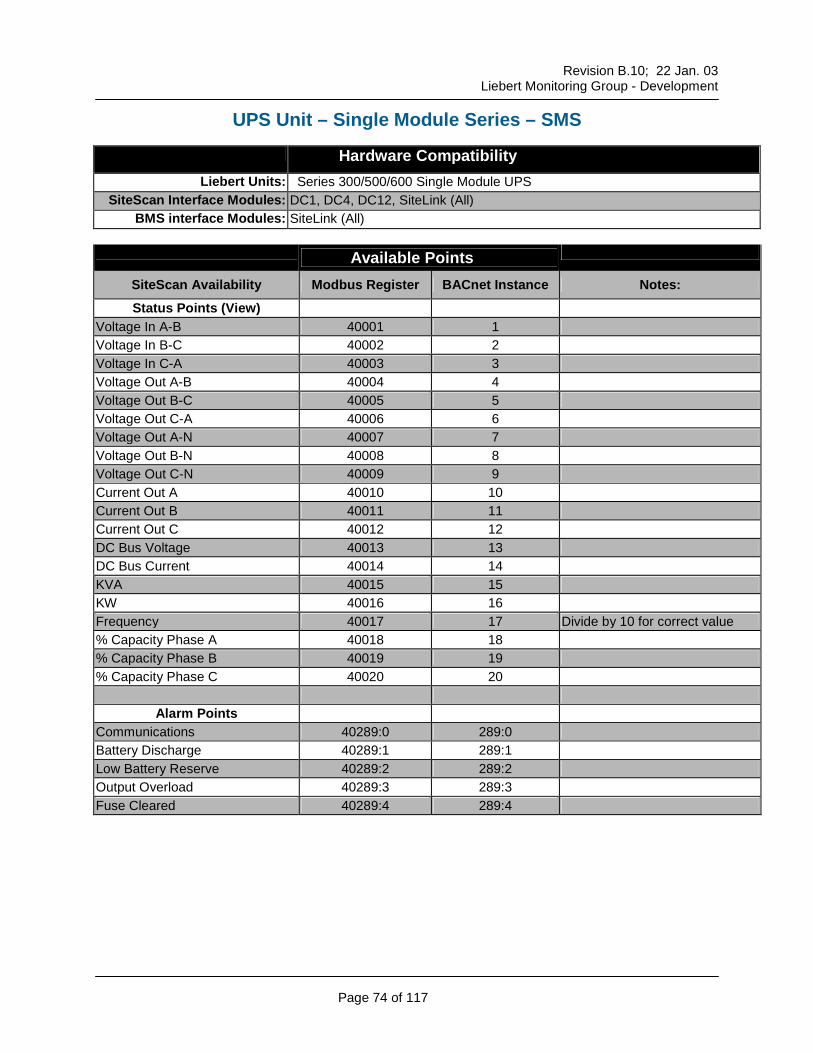
UPS Unit – Single Module Series – SMS
Hardware Compatibility Liebert Units: Series 300/500/600 Single Module UPS
SiteScan Availability Modbus Register BACnet Instance Notes: Status Points (View)
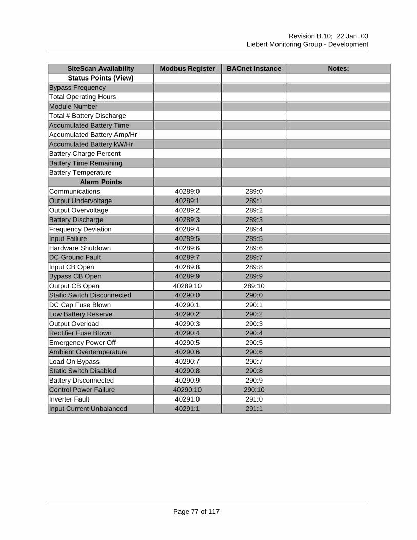
Voltage In A-B 40001 1 Voltage In B-C 40002 2 Voltage In C-A 40003 3 Voltage Out A-B 40004 4 Voltage Out B-C 40005 5 Voltage Out C-A 40006 6 Voltage Out A-N 40007 7 Voltage Out B-N 40008 8 Voltage Out C-N 40009 9 Current Out A 40010 10 Current Out B 40011 11 Current Out C 40012 12 DC Bus Voltage 40013 13 DC Bus Current 40014 14 KVA 40015 15 KW 40016 16 Frequency 40017 17 Divide by 10 for correct value % Capacity Phase A 40018 18 % Capacity Phase B 40019 19 % Capacity Phase C 40020 20
Alarm Points Emergency Power Off 40289:5 289:5 Ambient Overtemperature 40289:6 289:6 Load On Bypass 40289:7 289:7 Static Switch Disabled 40289:8 289:8 Battery Disconnected 40289:9 289:9 Module Cooling Failure 40289:10 289:10 Control Power Failure 40290:0 290:0 Overload Shutdown 40290:1 290:1
Setpoints (View) None
Control Points (Set) None
Trendable Points (Set) Voltage In A-B Voltage In B-C Voltage In C-A Voltage Out A-B Voltage Out B-C Voltage Out C-A Voltage Out A-N Voltage Out B-N Voltage Out C-N Current Out A Current Out B Current Out C % Capacity Phase A % Capacity Phase B % Capacity Phase C DC Bus Voltage DC Bus Current KW KVA
Reports Trend Status
Revision B.10; 22 Jan. 03
Liebert Monitoring Group - Development
Page 76 of 117
UPS Unit – Single Module UPS – S600 Ext. Prot. – SM4
Hardware Compatibility Liebert Units: Series 600 SMS
SiteScan Availability Modbus Register BACnet Instance Notes: Status Points (View)
Input Voltage A-B 40001 1 Input Voltage B-C 40002 2 Input Voltage C-A 40003 3 Output Voltage A-B 40004 4 Output Voltage B-C 40005 5 Output Voltage C-A 40006 6 Output Voltage A-N Output Voltage B-N Output Voltage C-N Output Amps Phase A 40007 7 Output Amps Phase B 40008 8 Output Amps Phase C 40009 9 DC Bus Voltage 40010 10 Battery Current 40011 11 KVA 40012 12 KW 40013 13 Critical Bus Frequency 40014 14 Divide by 10 for correct value % Capacity Phase A 40015 15 % Capacity Phase B 40016 16 % Capacity Phase C 40017 17 Bypass Voltage A-B 40018 18 Bypass Voltage B-C 40019 19 Bypass Voltage C-A 40020 20 Input Amps Phase A 40021 21 Input Amps Phase B 40022 22 Input Amps Phase C 40023 23 Bypass Frequency 40024 24 Divide by 10 for correct value
Revision B.10; 22 Jan. 03
Liebert Monitoring Group - Development
Page 77 of 117
SiteScan Availability Modbus Register BACnet Instance Notes: Status Points (View)
Bypass Frequency Total Operating Hours Module Number Total # Battery Discharge Accumulated Battery Time Accumulated Battery Amp/Hr Accumulated Battery kW/Hr Battery Charge Percent Battery Time Remaining Battery Temperature
Alarm Points Communications 40289:0 289:0 Output Undervoltage 40289:1 289:1 Output Overvoltage 40289:2 289:2 Battery Discharge 40289:3 289:3 Frequency Deviation 40289:4 289:4 Input Failure 40289:5 289:5 Hardware Shutdown 40289:6 289:6 DC Ground Fault 40289:7 289:7 Input CB Open 40289:8 289:8 Bypass CB Open 40289:9 289:9 Output CB Open 40289:10 289:10 Static Switch Disconnected 40290:0 290:0 DC Cap Fuse Blown 40290:1 290:1 Low Battery Reserve 40290:2 290:2 Output Overload 40290:3 290:3 Rectifier Fuse Blown 40290:4 290:4 Emergency Power Off 40290:5 290:5 Ambient Overtemperature 40290:6 290:6 Load On Bypass 40290:7 290:7 Static Switch Disabled 40290:8 290:8 Battery Disconnected 40290:9 290:9 Control Power Failure 40290:10 290:10 Inverter Fault 40291:0 291:0 Input Current Unbalanced 40291:1 291:1
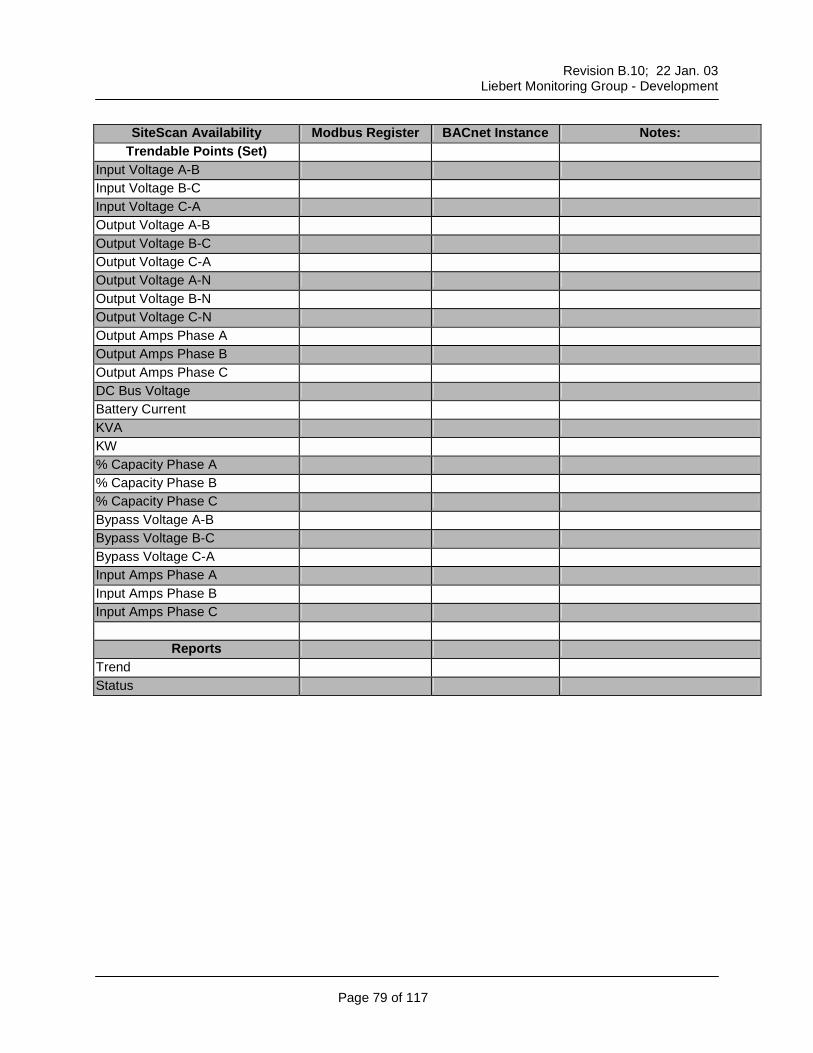
Trendable Points (Set) Input Voltage A-B Input Voltage B-C Input Voltage C-A Output Voltage A-B Output Voltage B-C Output Voltage C-A Output Voltage A-N Output Voltage B-N Output Voltage C-N Output Amps Phase A Output Amps Phase B Output Amps Phase C DC Bus Voltage Battery Current KVA KW % Capacity Phase A % Capacity Phase B % Capacity Phase C Bypass Voltage A-B Bypass Voltage B-C Bypass Voltage C-A Input Amps Phase A Input Amps Phase B Input Amps Phase C
Reports Trend Status
Revision B.10; 22 Jan. 03
Liebert Monitoring Group - Development
Page 80 of 117
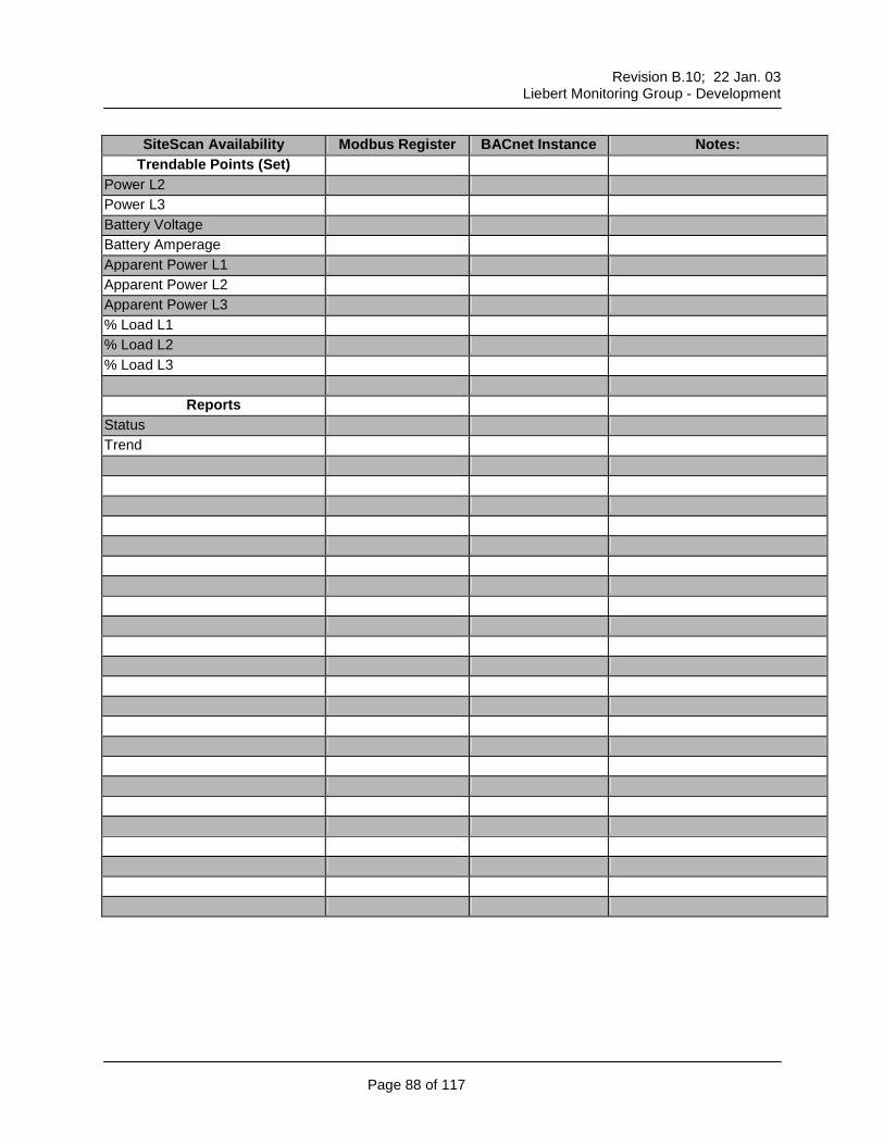
UPS Unit – Multi-Module SICE 7200 & HiPulse UPS – SMM
SiteScan Availability Modbus Register BACnet Instance Notes: Status Points (View)
Output Voltage L1-L2 40001 1 Output Voltage L2-L3 40002 2 Output Voltage L3-L1 40003 3 Output Voltage L1-N Output Voltage L2-N Output Voltage L3-N Output Amps L1 40004 4 Output Amps L2 40005 5 Output Amps L3 40006 6 Output Amps Neutral Power L1 40007 7 Power L2 40008 8 Power L3 40009 9 Bypass Frequency 40010 10 Divide by 10 for correct value Inverter Frequency 40011 11 Divide by 10 for correct value Input Voltage L1-L2 Input Voltage L2-L3 Input Voltage L3-L1 Battery Voltage 40012 12 Battery Amperage 40013 13 Apparent Power L1 40014 14 Apparent Power L2 40015 15 Apparent Power L3 40016 16 % Load L1 40017 17 % Load L2 40018 18 % Load L3 40019 19 Module Number
Revision B.10; 22 Jan. 03
Liebert Monitoring Group - Development
Page 81 of 117
SiteScan Availability Modbus Register BACnet Instance Notes: Status Points (View)
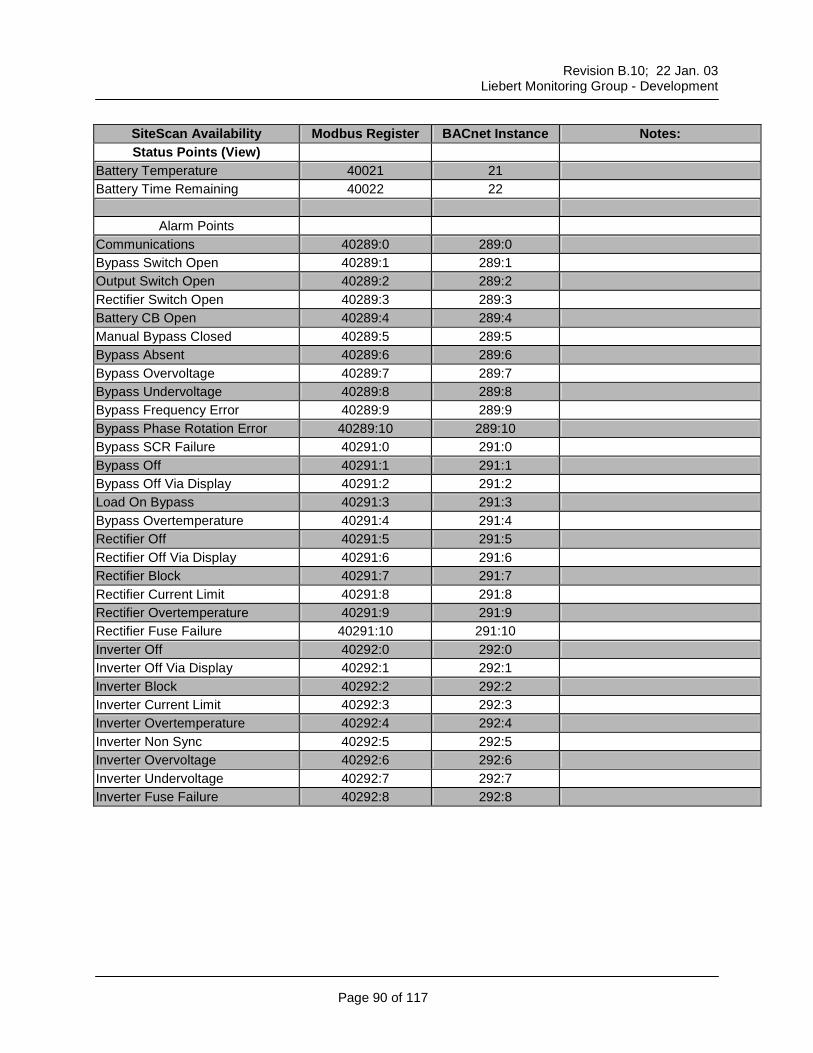
% Battery Charge 40020 20 Battery Temperature 40021 21 Battery Time Remaining 40022 22
Alarm Points Communications 40289:0 289:0 Bypass Switch Open 40289:1 289:1 Output Switch Open 40289:2 289:2 Rectifier Switch Open 40289:3 289:3 Battery CB Open 40289:4 289:4 Manual Bypass Closed 40289:5 289:5 Bypass Absent 40289:6 289:6 Bypass Overvoltage 40289:7 289:7 Bypass Undervoltage 40289:8 289:8 Bypass Frequency Error 40289:9 289:9 Bypass Phase Rotation Error 40289:10 289:10 Bypass SCR Failure 40290:0 290:0 Bypass Off 40290:1 290:1 Bypass Off Via Display 40290:2 290:2 Load On Bypass 40290:3 290:3 Bypass Overtemperature 40290:4 290:4 Rectifier Off 40290:5 290:5 Rectifier Off Via Display 40290:6 290:6 Rectifier Block 40290:7 290:7 Rectifier Current Limit 40290:8 290:8 Rectifier Overtemperature 40290:9 290:9 Rectifier Fuse Failure 40290:10 290:10 Inverter Off 40291:0 291:0 Inverter Off Via Display 40291:1 291:1 Inverter Block 40291:2 291:2 Inverter Current Limit 40291:3 291:3 Inverter Overtemperature 40291:4 291:4 Inverter Non Sync 40291:5 291:5 Inverter Overvoltage 40291:6 291:6 Inverter Undervoltage 40291:7 291:7
Alarm Points Synchronization Inhibited ECO – Mode On
Setpoints (View) Power Rating Configuration Nominal Voltage Low Level Input Voltage Upper Level Input Voltage Low Level Output Voltage Upper Level Output Voltage Nominal Frequency Frequency Tolerance Slew Rate # of Battery Cells Rated Capacity Pre-End Discharge End of Discharge per Cell Maximum Voltage per Cell Year Month Day Hour Minute Second
Control Points (Set) Date & Time Sync 40349 349
Trendable Points (Set) Output Voltage L1-L2 Output Voltage L2-L3 Output voltage L3-L1
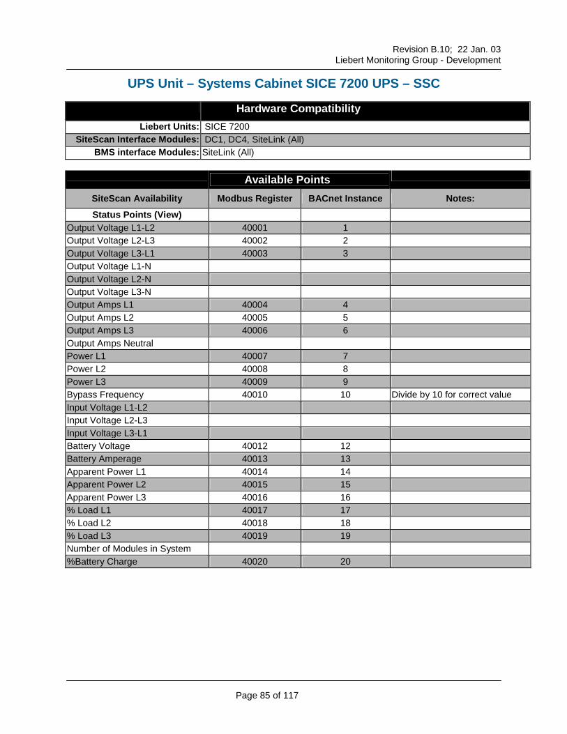
SiteScan Availability Modbus Register BACnet Instance Notes: Status Points (View)
Output Voltage L1-L2 40001 1 Output Voltage L2-L3 40002 2 Output Voltage L3-L1 40003 3 Output Voltage L1-N Output Voltage L2-N Output Voltage L3-N Output Amps L1 40004 4 Output Amps L2 40005 5 Output Amps L3 40006 6 Output Amps Neutral Power L1 40007 7 Power L2 40008 8 Power L3 40009 9 Bypass Frequency 40010 10 Divide by 10 for correct value Input Voltage L1-L2 Input Voltage L2-L3 Input Voltage L3-L1 Battery Voltage 40012 12 Battery Amperage 40013 13 Apparent Power L1 40014 14 Apparent Power L2 40015 15 Apparent Power L3 40016 16 % Load L1 40017 17 % Load L2 40018 18 % Load L3 40019 19 Number of Modules in System %Battery Charge 40020 20
Revision B.10; 22 Jan. 03
Liebert Monitoring Group - Development
Page 86 of 117
SiteScan Availability Modbus Register BACnet Instance Notes: Status Points (View)
Battery Temperature 40021 21 Battery Time Remaining 40022 22
Alarm Points Communications 40289:0 289:0 Bypass Switch Open 40289:1 289:1 Output Switch Open 40289:2 289:2 Battery CB Open 40289:3 289:3 Manual Bypass Closed 40289:4 289:4 Bypass Absent 40289:5 289:5 Bypass Overvoltage 40289:6 289:6 Bypass Undervoltage 40289:7 289:7 Bypass Frequency Error 40289:8 289:8 Bypass Phase Rotation Error 40289:9 289:9 Bypass SCR Failure 40289:10 289:10 Bypass Off 40290:0 290:0 Bypass Off Via Display 40290:1 290:1 Load On Bypass 40290:2 290:2 Bypass Overtemperature 40290:3 290:3 Inverter Non Sync 40290:4 290:4 Output Overvoltage 40290:5 290:5 Output Undervoltage 40290:6 290:6 Output No Voltage 40290:7 290:7 Output Waveform Error 40290:8 290:8 Transfer Count Block 40290:9 290:9 Overload Shutdown 40290:10 290:10 Overtemperature Shutdown 40291:0 291:0 Emergency Stop 40291:1 291:1 Overload Present 40291:2 291:2 Overload Shutdown Timeout 40291:3 291:3 Bad EEPROM 40291:4 291:4 Error LRC Par P1 40291:5 291:5 Error LRC Par P2 Error LRC Par P3
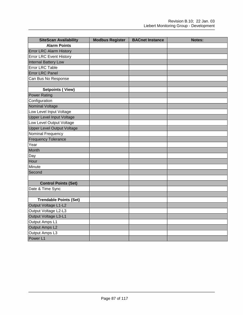
Alarm Points Error LRC Alarm History Error LRC Event History Internal Battery Low Error LRC Table Error LRC Panel Can Bus No Response
Setpoints ( View) Power Rating Configuration Nominal Voltage Low Level Input Voltage Upper Level Input Voltage Low Level Output Voltage Upper Level Output Voltage Nominal Frequency Frequency Tolerance Year Month Day Hour Minute Second
Control Points (Set) Date & Time Sync
Trendable Points (Set) Output Voltage L1-L2 Output Voltage L2-L3 Output Voltage L3-L1 Output Amps L1 Output Amps L2 Output Amps L3 Power L1
Trendable Points (Set) Power L2 Power L3 Battery Voltage Battery Amperage Apparent Power L1 Apparent Power L2 Apparent Power L3 % Load L1 % Load L2 % Load L3
Reports Status Trend
Revision B.10; 22 Jan. 03
Liebert Monitoring Group - Development
Page 89 of 117
UPS Unit – Single Module SICE 7200 & HiPulse UPS – SSM
Setpoints (View) Power Rating Configuration Nominal Voltage Low Level Input Voltage Upper Level Input Voltage Low Level Output Voltage Upper Level Output Voltage Nominal Frequency Frequency Tolerance Slew Rate # of Battery Cells Rated Capacity Pre-End Discharge End of Discharge per Cell Maximum Voltage per Cell Year Month Day Hour Minute Second
Control Points (Set) Date & Time Sync
Trendable Points (Set) Output Voltage L1-L2 Output Voltage L2-L3 Output Voltage L3-L1 Output Amps L1 Output Amps L2 Output Amps L3 Power L1 Power L2 Power L3 Battery Voltage
SiteScan Availability Modbus Register BACnet Instance Notes: Status Points (View)
Battery Time Remaining Last Battery Test Passed Last Self Test Passed Voltage In Phase A Voltage In Phase B Voltage In Phase C Current In Phase A Current In Phase B Current In Phase C Voltage Out Phase A Voltage Out Phase B Current Out Phase A Current Out Phase B Voltage Bypass Phase A Voltage Bypass Phase B Current Bypass Phase A Current Bypass Phase B VA Inverter Load Percentage Load Inverter Temperature PFC Temperature Battery Temperature Battery Voltage Battery Current Input Frequency Output Frequency
Revision B.10; 22 Jan. 03
Liebert Monitoring Group - Development
Page 95 of 117
SiteScan Availability Modbus Register BACnet Instance Notes: Status Points (View)
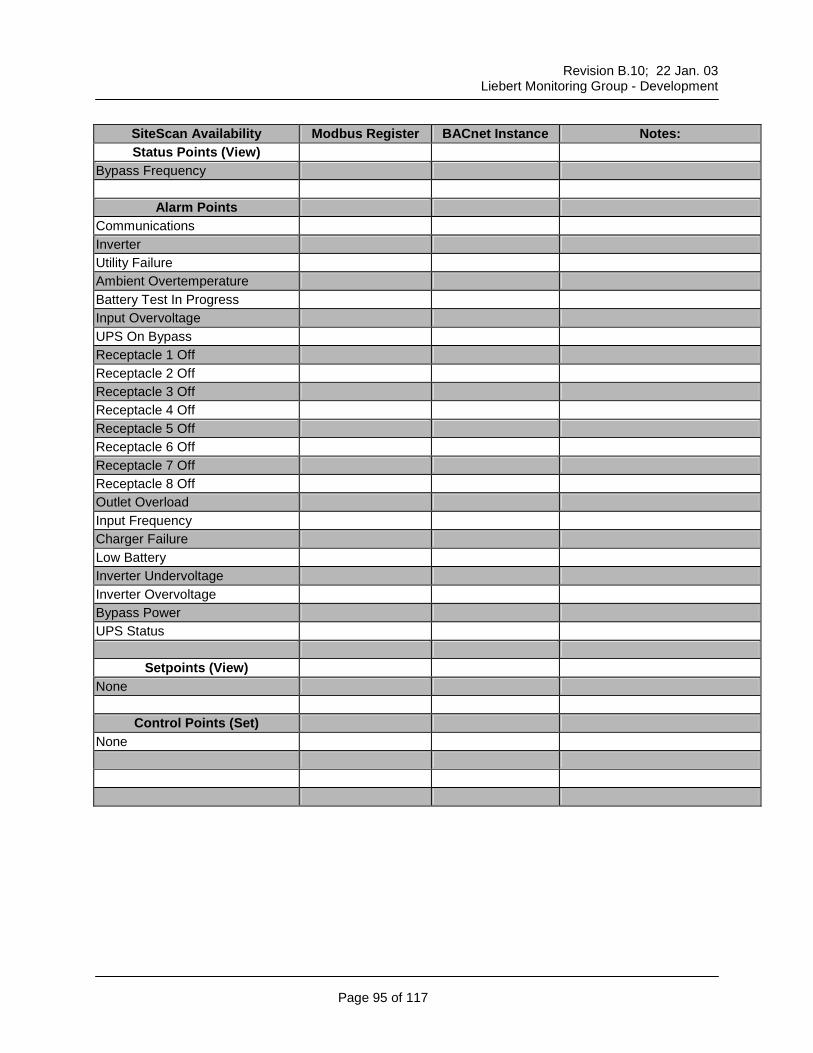
Bypass Frequency
Alarm Points Communications Inverter Utility Failure Ambient Overtemperature Battery Test In Progress Input Overvoltage UPS On Bypass Receptacle 1 Off Receptacle 2 Off Receptacle 3 Off Receptacle 4 Off Receptacle 5 Off Receptacle 6 Off Receptacle 7 Off Receptacle 8 Off Outlet Overload Input Frequency Charger Failure Low Battery Inverter Undervoltage Inverter Overvoltage Bypass Power UPS Status
Trendable Points (Set) Voltage In Phase A Voltage In Phase B Voltage In Phase C Current In Phase A Current In Phase B Current In Phase C Voltage Out Phase A Voltage Out Phase B Current Out Phase A Current Out Phase B Voltage Bypass Phase A Voltage Bypass Phase B Current Bypass Phase A Current Bypass Phase B VA Inverter Load Percentage Load Inverter Temperature PFC Temperature Battery Temperature Battery Voltage Battery Current Input Frequency Output Frequency Bypass Frequency
SiteScan Availability Modbus Register BACnet Instance Notes: Status Points (View)
Bypass Voltage A-N 40016 16 Bypass Voltage B-N 40017 17 Bypass Voltage C-N 40018 18 Voltage In A-N 40001 1 Voltage In B-N 40002 2 Voltage In C-N 40003 3 Voltage Out A-N 40004 4 Voltage Out B-N 40005 5 Voltage Out C-N 40006 6 Current Out A 40007 7 Current Out B 40008 8 Current Out C 40009 9 DC Bus Voltage 40010 10 DC Bus Current 40011 11 KVA 40012 12 KW 40013 13 Inverter Temperature 40021 21 PFC Temperature 40022 22 Battery Temperature 40023 23 Battery Test Status Input Frequency Bypass Frequency 40024 24 Output Frequency 40014 14 Divide by 10 for correct value Current In A Current In B Current In C % Capacity 40015 15
Revision B.10; 22 Jan. 03
Liebert Monitoring Group - Development
Page 98 of 117
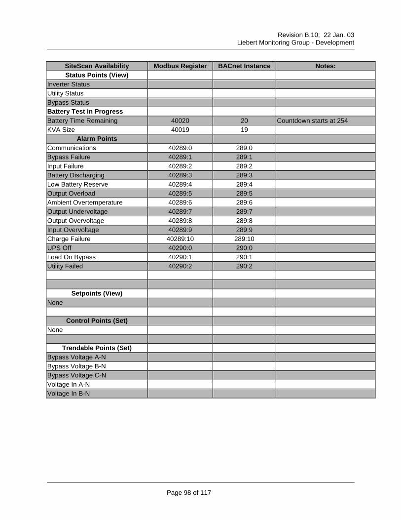
SiteScan Availability Modbus Register BACnet Instance Notes: Status Points (View)
Inverter Status Utility Status Bypass Status Battery Test in Progress Battery Time Remaining 40020 20 Countdown starts at 254 KVA Size 40019 19
Trendable Points (Set) Voltage In C-N Voltage Out A-N Voltage Out B-N Voltage Out C-N Current In A Current In B Current In C Current Out A Current Out B Current Out C % Capacity DC Bus Voltage DC Bus Current KW KVA Battery Time
Reports Trend Status
Revision B.10; 22 Jan. 03
Liebert Monitoring Group - Development
Page 100 of 117
UPS Unit – Single Module Series AP301/302 – SM3
Hardware Compatibility Liebert Units: Single Module UPS AP301/302
Status Points (View) Bypass Voltage A-N 40016 16 Bypass Voltage B-N 40017 17 Bypass Voltage C-N 40018 18 Voltage in A-N 40001 1 Voltage in B-N 40002 2 Voltage in C-N 40003 3 Voltage Out A-N 40004 4 Voltage Out B-N 40005 5 Voltage Out C-N 40006 6 Current In A Current In B Current In C Current Out A 40007 7 Current Out B 40008 8 Current Out C 40009 9 % Capacity 40015 15 DC Bus Voltage 40010 10 DC Bus Current 40011 11 KW 40012 12 KVA 40013 13 Input Frequency Bypass Frequency Output Frequency 40014 14 Divide by 10 for correct value Last Battery Test Status 40022 22 0=failed / 1= passed Inverter Status 40023 23 0=off / 1=on Model Number 40020 20 KVA Size 40019 19
Revision B.10; 22 Jan. 03
Liebert Monitoring Group - Development
Page 101 of 117
SiteScan Availability Modbus Register BACnet Instance Notes: Status Points (View)
Utility Status Bypass Status 40024 24 0=not present / 1=present Battery Test In Progress Battery Time Remaining 40021 21 Countdown timer starts at 254
Trendable Points (Set) Bypass Voltage A-N Bypass Voltage B-N Bypass Voltage C-N Voltage In A-N Voltage In B-N Voltage In C-N Voltage Out A-N Voltage Out B-N Voltage Out C-N Current In A Current In B Current In C Current Out A Current Out B Current Out C % Capacity DC Bus Voltage DC Bus Current KW KVA Input Frequency Bypass Frequency Output Frequency Battery Time
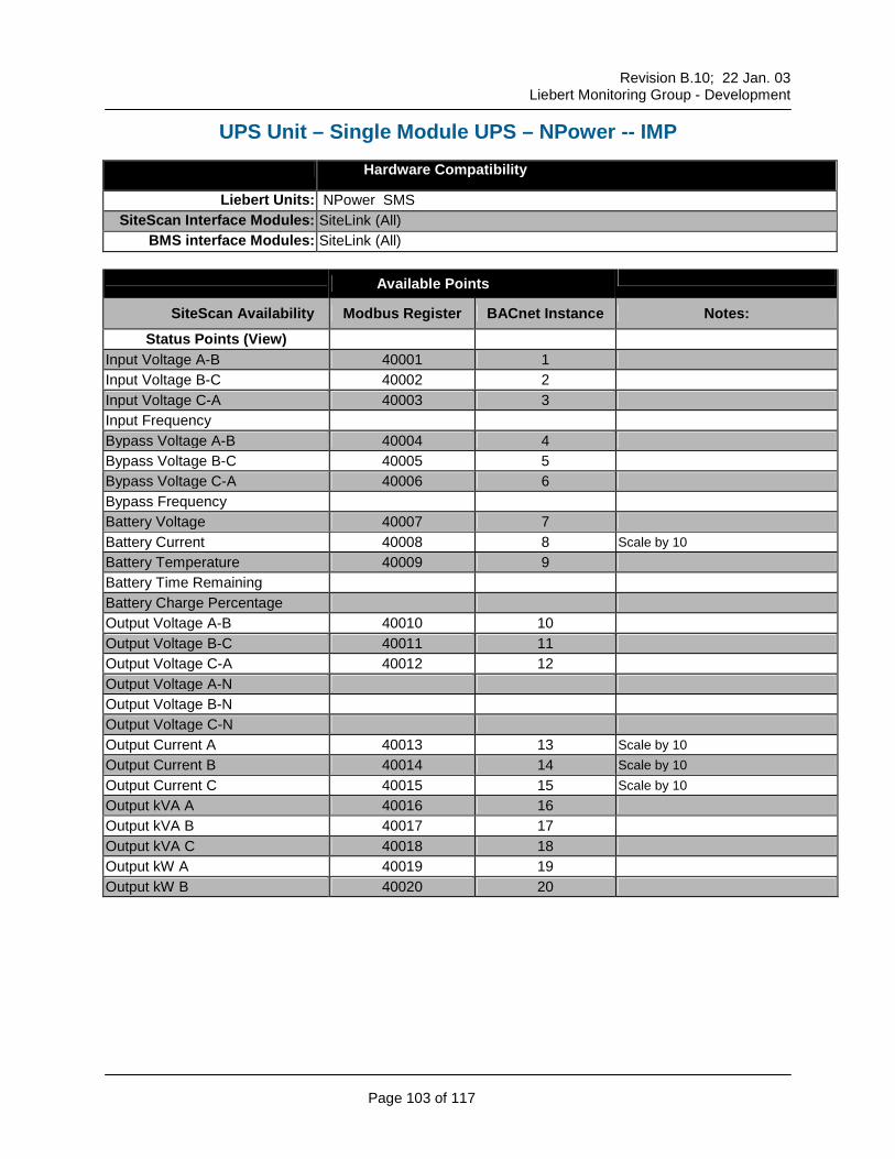
SiteScan Availability Modbus Register BACnet Instance Notes: Status Points (View)
Input Voltage A-B 40001 1 Input Voltage B-C 40002 2 Input Voltage C-A 40003 3 Input Frequency Bypass Voltage A-B 40004 4 Bypass Voltage B-C 40005 5 Bypass Voltage C-A 40006 6 Bypass Frequency Battery Voltage 40007 7 Battery Current 40008 8 Scale by 10 Battery Temperature 40009 9 Battery Time Remaining Battery Charge Percentage Output Voltage A-B 40010 10 Output Voltage B-C 40011 11 Output Voltage C-A 40012 12 Output Voltage A-N Output Voltage B-N Output Voltage C-N Output Current A 40013 13 Scale by 10 Output Current B 40014 14 Scale by 10 Output Current C 40015 15 Scale by 10 Output kVA A 40016 16 Output kVA B 40017 17 Output kVA C 40018 18 Output kW A 40019 19 Output kW B 40020 20
Revision B.10; 22 Jan. 03
Liebert Monitoring Group - Development
Page 104 of 117
SiteScan Availability Modbus Register BACnet Instance Notes: Status Points (View)
Output kW C 40021 21 Output Frequency 40022 22 Scale by 10 Rated kVA Percentage 40023 23 Rated kW Percentage 40024 24 SBS Line Contact On/Off SBS Load Contact On/Off Input Delta Contact On/Off Input Wye Contact On/Off Output Contact On/Off Battery Breaker On/Off Trap Filter Contact On/Off Int. Mbypass Sw. On/Off Ext. Mbypass Sw. On/Off Year Month Day Hour Minutes Seconds
Alarms Points Communications 40289:00 Battery Fuse Failure 40289:01 Battery Low Transfer 40289:02 DC Overvoltage Transient 40289:03 Input Phase Rotation Err 40289:04 Rectifier Fuse Failure 40289:05 Bypass Frequency Error 40289:06 Bypass Overload Shutdown 40289:07 Bypass Phase Rotation Error 40289:08 Inverter Overload Transfer 40289:09 Inverter Fuse Failure 40289:10 Output Overvolt Transfer 40289:11 Output Undervolt Transfer 40289:12 SBS SCR Open 40289:13
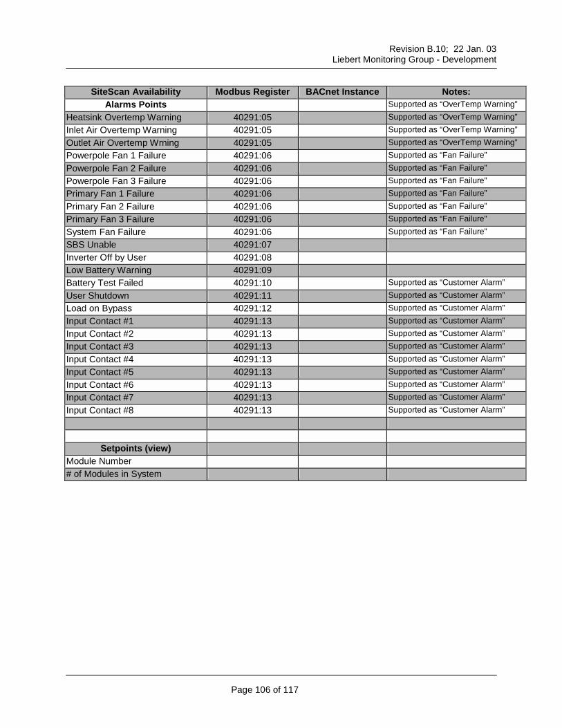
Alarms Points Supported as “OverTemp Warning” Heatsink Overtemp Warning 40291:05 Supported as “OverTemp Warning” Inlet Air Overtemp Warning 40291:05 Supported as “OverTemp Warning” Outlet Air Overtemp Wrning 40291:05 Supported as “OverTemp Warning” Powerpole Fan 1 Failure 40291:06 Supported as “Fan Failure” Powerpole Fan 2 Failure 40291:06 Supported as “Fan Failure” Powerpole Fan 3 Failure 40291:06 Supported as “Fan Failure” Primary Fan 1 Failure 40291:06 Supported as “Fan Failure” Primary Fan 2 Failure 40291:06 Supported as “Fan Failure” Primary Fan 3 Failure 40291:06 Supported as “Fan Failure” System Fan Failure 40291:06 Supported as “Fan Failure” SBS Unable 40291:07 Inverter Off by User 40291:08 Low Battery Warning 40291:09 Battery Test Failed 40291:10 Supported as “Customer Alarm” User Shutdown 40291:11 Supported as “Customer Alarm” Load on Bypass 40291:12 Supported as “Customer Alarm” Input Contact #1 40291:13 Supported as “Customer Alarm” Input Contact #2 40291:13 Supported as “Customer Alarm” Input Contact #3 40291:13 Supported as “Customer Alarm” Input Contact #4 40291:13 Supported as “Customer Alarm” Input Contact #5 40291:13 Supported as “Customer Alarm” Input Contact #6 40291:13 Supported as “Customer Alarm” Input Contact #7 40291:13 Supported as “Customer Alarm” Input Contact #8 40291:13 Supported as “Customer Alarm”
Setpoints (view) Module Number # of Modules in System
Revision B.10; 22 Jan. 03
Liebert Monitoring Group - Development
Page 107 of 117
SiteScan Availability Modbus Register BACnet Instance Notes: Control Points (Set)
Date Time
Trendable Points Input Volts A-B Input Volts B-C Input Volts C-A Bypass Volts A-B Bypass Volts B-C Bypass Volts C-A Battery Voltage Battery Current Battery Temperature (Degree C) Output Volts A-B Output Volts B-C Output Volts C-A Output Current Phase A Output Current Phase B Output Current Phase C Output kVA Phase A Output kVA Phase B Output kVA Phase C Output kW Phase A Output kW Phase B Output kW Phase C Percent Rated kVA Percent Rated kW
SiteScan Availability Modbus Register BACnet Instance Notes: Status Points (View)
Unit 1 40001 1 1=on / 0=0ff Unit 2 40002 2 1=on / 0=0ff Unit 3 40003 3 1=on / 0=0ff Unit 4 40004 4 1=on / 0=0ff Unit 5 40005 5 1=on / 0=0ff Unit 6 40006 6 1=on / 0=0ff Unit 7 40007 7 1=on / 0=0ff Unit 8 40008 8 1=on / 0=0ff
Alarm Points Communications 40289:0 289:0 Common Alarm 1 40289:1 289:1 Common Alarm 2 40289:2 289:2 Common Alarm 3 40289:3 289:3 Common Alarm 4 40289:4 289:4 Common Alarm 5 40289:5 289:5 Common Alarm 6 40289:6 289:6 Common Alarm 7 40289:7 289:7 Common Alarm 8 40289:8 289:8 Emergency Power Operation 40289:9 289:9 EPO All Units 40289:10 289:10 High Temperature 40290:0 290:0 Low Temperature 40290:1 290:1 High Humidity 40290:2 290:2 Low Humidity 40290:3 290:3 Manual Override 40290:4 290:4
Trendable Points (Set) Temperature 1 Humidity 1 Temperature 2 Humidity 2
Trendable Points (Set) Temperature 3 Humidity 3 Temperature 4 Humidity 4 Temperature 5 Humidity 5 Temperature 6 Humidity 6 Temperature 7 Humidity 7 Temperature 8 Humidity 8