Autonomous Robotic Follower with License Plate Recognition Capability Khanh Le, Luis Sosa, Bryan Diaz, Victor Salomon Dept. of Electrical Engineering and Computer Science, University of Central Florida, Orlando, Florida, 32816-2450 Abstract — A computer vision based robotic follower system implementation is presented, and this robotic following mechanism is triggered by the use of an Automatic License Plate Recognition (ALPR) algorithm. The robot is trained at the moment of the event to use a tracking algorithm, this system tracks a lead vehicle using a sequence of images captured on video. On this paper the focus is a low cost, single board computer implementation, simulating the functioning as closely as possible of a regular motor vehicle. Index Terms — ALPR, Computer Vision, Autonomous Following, Single Board Computer, License Plate Recognition. I. INTRODUCTION As the computing technologies advance and become more cost effective we see more of these applied to different areas in our daily lives, one of which is the safety of the population in general. Because of this we see applications of computer vision such as in the case of facial image recognition or Automatic License Plate Recognition (ALPR). These solutions are implemented in systems used for applications such as automatic toll payments or access control for residential or industrial areas. This paper proposes a different application, using a ALPR algorithm a robot detects a license plate number, this extracted license plate number is then compared to a database simulating that which a law enforcement officer would have available, if the number extracted is matched to a license plate number which is black listed for any given reason, the robot will train itself to follow the said license plate. The system design is shown in Figure 1, the main element in the system is the single board computer, a Raspberry Pi 2 Model B, which provides a low cost platform to perform the processing needed for the computer vision is processed, as well as running the other processes involved in the testing case scenario. II. SYSTEM COMPONENTS A. Single Board Computer This is called a “brain” of our whole project. The Single Board Computer is unit where data is processing and command is sent out to another components in system. In this project, the most important job is how the Robot can recognize and detect the license plate. After that, it keep following without losing the target. We use image-processing for implementing this function. Raspberry Pi 2 Model B is a chosen one in pool of microcontroller market. Camera connected to the Pi will send image continuously to Pi, and then it will process these data to recognize the pattern on target to detect the license plate in black list. Also, when target is detected, Pi will base on analyzing image of target to determine its behavior and decide the action corresponding to this behavior. Pi also send out command to Motor Controller through Serial Communication for controlling the Robot motion to follow the target. Due to the relative distance between Robot and target, Pi will decide if motor need to accelerate or decelerate. Fig. 1 System Design Block Diagram B. Motor Controller This is a system controlling whole body of ACR. It makes ACR run and respond to target’s behavior based on command sent from MCU. Raspberry Pi in MCU does image-processing for detecting a target and then make decision of what action follower need to do. It will command motor controller system to control servo motor for turning or brushed DC motor for going forward or backward and accelerating or decelerating. This command will be made through serial communication.
Transcript
Autonomous Robotic Follower
with License Plate Recognition
Capability
Khanh Le, Luis Sosa, Bryan Diaz,
Victor Salomon
Dept. of Electrical Engineering and Computer
Science, University of Central Florida, Orlando,
Florida, 32816-2450
Abstract — A computer vision based robotic follower system
implementation is presented, and this robotic following mechanism is triggered by the use of an Automatic License Plate Recognition (ALPR) algorithm. The robot is trained at
the moment of the event to use a tracking algorithm, this system tracks a lead vehicle using a sequence of images captured on video. On this paper the focus is a low cost, single
board computer implementation, simulating the functioning as closely as possible of a regular motor vehicle.
Index Terms — ALPR, Computer Vision, Autonomous Following, Single Board Computer, License Plate Recognition.
I. INTRODUCTION
As the computing technologies advance and become
more cost effective we see more of these applied to
different areas in our daily lives, one of which is the safety
of the population in general. Because of this we see
applications of computer vision such as in the case of facial
image recognition or Automatic License Plate Recognition
(ALPR). These solutions are implemented in systems used
for applications such as automatic toll payments or access
control for residential or industrial areas.
This paper proposes a different application, using a
ALPR algorithm a robot detects a license plate number, this
extracted license plate number is then compared to a
database simulating that which a law enforcement officer
would have available, if the number extracted is matched to
a license plate number which is black listed for any given
reason, the robot will train itself to follow the said license
plate. The system design is shown in Figure 1, the main
element in the system is the single board computer, a
Raspberry Pi 2 Model B, which provides a low cost
platform to perform the processing needed for the computer
vision is processed, as well as running the other processes
involved in the testing case scenario.
II. SYSTEM COMPONENTS
A. Single Board Computer
This is called a “brain” of our whole project. The
Single Board Computer is unit where data is processing
and command is sent out to another components in
system. In this project, the most important job is how the
Robot can recognize and detect the license plate. After
that, it keep following without losing the target. We use
image-processing for implementing this function.
Raspberry Pi 2 Model B is a chosen one in pool of
microcontroller market. Camera connected to the Pi will
send image continuously to Pi, and then it will process
these data to recognize the pattern on target to detect the
license plate in black list. Also, when target is detected,
Pi will base on analyzing image of target to determine its
behavior and decide the action corresponding to this
behavior. Pi also send out command to Motor Controller
through Serial Communication for controlling the Robot
motion to follow the target. Due to the relative distance
between Robot and target, Pi will decide if motor need to
accelerate or decelerate.
Fig. 1 System Design Block Diagram
B. Motor Controller
This is a system controlling whole body of ACR. It
makes ACR run and respond to target’s behavior based
on command sent from MCU. Raspberry Pi in MCU does
image-processing for detecting a target and then make
decision of what action follower need to do. It will
command motor controller system to control servo motor
for turning or brushed DC motor for going forward or
backward and accelerating or decelerating. This
command will be made through serial communication.
This system has its own micro-controller which is
separated from MCU, which makes designing hardware
and programming to be easier. The micro-controller
communicates with servo motor directly through I/O pins
but controls the brushed DC motor by using H-Bridge as
middle guy.
C. Ultra Sonic Sensors
This type of sensors use ultra-sonic waves to
determine a given distance. One of the biggest
advantages compared to other sensors which have similar
capabilities is that this type of sensor can be used inside
or outside building because the sunlight does not affect
its operation as it does for infrared sensors, and because
of this reason, an ultrasonic sensor is relatively more
accurate.
The ultrasonic sensor has an output which emits an
ultrasonic signal and an input which receives it after this
bounces on a surface. Based on the time passed between
signal sent out and the return echo received, the distance
can be calculated, providing a high rate of accuracy, with
ranges of operation ranging from 10cm to more than
80cm.
D. Inertia Measuring Unit (IMU)
This inertial measurement unit (IMU) is a
component of navigational equipment, and it is usually
composed by a combination of accelerometers,
gyroscopes, magnetometers and sometimes other
electrical sensors inertial measurement units can measure
orientation, acceleration rates, and rotational changes.
These are often produced in different styles with
differing levels accuracy which is measured in degrees of
freedom.
The inertial measurement unit can also be used to
measure gravitational forces which are commonly called
g-forces and by measuring the various forces and keeping
track of them, the inertial measurement unit is able to
produce a linear record of these measurements, which are
then processed and the data that results is used to
calculate the inertial measurement unit’s position based
on reported velocity, direction, and time elapsed. This
data can be directly overlaid onto an electronic mapping
system that can tell the inertial measurement unit its
location and orientation with respect to a point, which
can be useful to detect a possible accident of the motor
vehicle, adding an extra safety measure to our system.
E. Power Supply
The power supply it is a very important part of the
project. It is what gives life and energy needed for the
systems to perform effectively. If the power is not
supplied efficiently, malfunctions in the subsystem may
arise. In Figure 2, a high level diagram of the power
supply system is represented.
Fig. 2 High Level Diagram of power system
1. Main DC source
The system Main DC source consists of a rechargeable
battery. This battery is responsible of supplying enough
power for the system to work efficiently. Three different
voltage regulators will be in charge of stepping down the
voltage accordingly to the need of each load
Main Dc Source consists of a rechargeable battery.
There were several requirements needed to be taken into
account in the selection of the battery. First, the battery
must be able to last at least 30 minutes at full load. Also, it
must be small and lightweight, the latter especially
important, because the performance of the ACR car might
be affected if the weight increases. After much
consideration and research, the battery chemistry selected
for the project was the Lithium Polymer Ion battery. This
battery chemistry provides a lightweight design, with
improved safety to overcharging and has a low probability
of electrolyte leakage which can negatively affect the
performance of the battery.
2. Voltage Regulators
The second part of the power supply diagram are the
voltage regulators. There were to main technologies to be
consider for our project, linear vs switching voltage
Main DC Source
Voltage Regulator
Motor
Voltage Regulator
Raspberry Pi
Camera
Voltage Regulator
MCU
Sensors
Servo Motor
(Steering)
regulators. Table #1 shows the difference between the two
technologies.
Features Linear
Voltage
Regulator
Switching
Voltage
Regulator
Function Step down
only, output
voltage must
be less than
input voltage
Steps up or Steps
Down the
voltage, can
produce multiple
outputs.
Size Small to
medium in
portable
design, may
be even larger
if heat sink is
needed
Large than linear
at low power, but
smaller in the
case where linear
requires a heat
sink
Efficiency Low to
medium
High
Noise Low Medium to high
due to ripple
effect
Output
Ripple
Very small
almost
negligible
Large
Waste
Heat
High, when
load and
voltage
difference is
high
Low, most
components will
run cool for low
power levels
Table #1.Linear Voltage Regulator Vs Switching Voltage
Regulator
The ACR car uses switching voltage regulators. Based on
the research, switching regulators are more effective and
highly efficient, in stepping down a voltage, when the
difference between the two voltages is large. Having a high
efficient regulator is necessary in our design because our
main source of power is a battery. It is necessary that the
power supplied to the system is not wasted in the form of
heat.
III. HARDWARE DETAILS
A. Image-Processing:
We are using the raspberry Pi 2 model for image
processing. There are a number of advantages of using the
Pi which is why we chose it. It has an operating system
which makes it much easier to use for the image processing
libraries. It has multiple USBs which is good because the
camera is a USB camera, we can also connect a keyboard
and a mouse to make it easier to interact with the Pi. It also
has a HDMI port so we can connect it to a monitor and see
what’s happening. Since image processing is very
performance intense we decided to buy two heat sinks and
one little fan for the main Pi processor. With the heat sinks
and the fan we are now able to overclock the Pi to
1000MHz and 500MHz for SDRAM which would make
the image processing a little faster.
B. Motor controller system
This system is composed of MSP430, Pololu motor
driver, Brushed DC motor, servo motor and voltage
level shifter between 3.3V and 5V.
1. MSP430G2553:
We pick MSP430g2553 to be this system
controller because we are familiar to this micro-
controller during Embedded System courses. Besides
that, it has same voltage level with Raspberry Pi
which is a whole project’s brain. MSP430 is able to
communicate with Raspberry Pi through Serial Port
by connecting directly TX pin on Pi to RX pin (Pin
1.1) of MSP430.
Fig. 3: MSP430 connection.
We only use MSP430 chip, not a whole launch pad,
for this project. In order to power it without the
board, we need to connect Vcc (Pin1) and Reset
(Pin16) to 3.3V. Besides that, pin20 is required to be
connected to ground. We are not going to use all the
pins of MSP430. This table #2 below shows the pins
used for connection with another components in
system.
Vcc (Pin1) 3.3V
GND (Pin20) Ground
Reset (Pin16) 3.3V
RX/P1.1 (Pin3) TX pin of Rasp Pi
P2.1 (Pin9) DIR pin of Pololu
P2.5 (Pin13) PWM pin of Pololu
P2.2 (Pin 10) Servo Motor
Table#2 Msp430 pin connection
2. Servo Motor:
The servo we use is a typical one for Remote
controlled car displayed in market place. There is no
special requirement for picking this component. In
general, Servo has 3 lines coming out for connections.
Brown is ground line, Red is Power Line and Orange
is signal line. Not same as MSP430, the servo needs
5V to be powered up. Therefore, Red Line will be
connected to 5V and then Signal Line (Orange) is
connected to P2.2 (Pin10) of Msp430. This micro-
controller will send a Pulse Code Modulation (PCM)
signal to servo in order to tell servo where the shaft
needs to go.
3. Brushed DC motor:
The model of DC brushed motor that we pick from
the marketplace is DS-540 Electric DC motor. It is
operating with full speed of 20000 rpm at 12V. We
are going to build a high speed chasing robot, so this
DS-540 are able to satisfy this speed requirement.
Also, the shaft generates a high torque to handle the
heavy load we will put on the car. The table #3 below
shows this motor specifications.
Rated Voltage 12V
Rated Current 2.6A
Full Speed 20000 rpm
Shaft Diameter 3mm
Shaft Length 10mm
Body Diameter 36mm
Total Length 68mm
Weight 161g
Table #3 DC motor specifications
4. Logic Level Shifter:
As we discuss in section 1, we use MSP430 as the
system micro-controller. It will send out signal to
Pololu motor driver to control the Brushed DC motor
(DS-540). However, logic connection of this Pololu
driver is designed to interface with 5V system, not
3.3V as MSP430 system. Therefore, we need logic
level shifter to convert signal from 3.3V level to 5V
level so that micro-controller can interface with
Pololu driver. The table #4 below show connections
for Level Shifter.
Low Level 3.3V
High Level 5V
A4 Pin9 of Msp430
B4 DIR pin of Pololu
A6 Pin13 of Msp430
B6 PWM pin of Pololu
GND Ground
Table #4 Level Shifter Connection
5. High Power Motor Driver:
This discrete MOSFET H-bridge motor driver
enables bidirectional control of one high-power DC
brushed motor. The little 1.3×0.8-inch board supports
a wide 5.5 to 30 V voltage range and is efficient
enough to deliver a continuous 15 A without a heat
sink. In this project, we supply a voltage 12V and
expected current will be around 2.5A but maybe 5A if
motor get stall. Also, this motor driver has own
protection if short circuit or overheat happen. Besides
that, the cost is only $40 and a lot cheaper than the
expensive amount for building H-bridge circuit on
PCB.
Fig. 4: motor driver board
We do not need to connect all the pins in Pololu
board. In typical motor control application, only DIR
and PWM are required for input signal. Besides that,
OUTA and OUTB will be connected to motor. 12V is
supply to V+ for powering motor and the driver. The
last one is GND connected to ground.
The operation of Pololu motor driver is really
simple to understand. DIR pin is low or high, which
determine the direction of motor (backward or
forward). Also, the PWM signal input through PWM
pin will control speed of the motor.
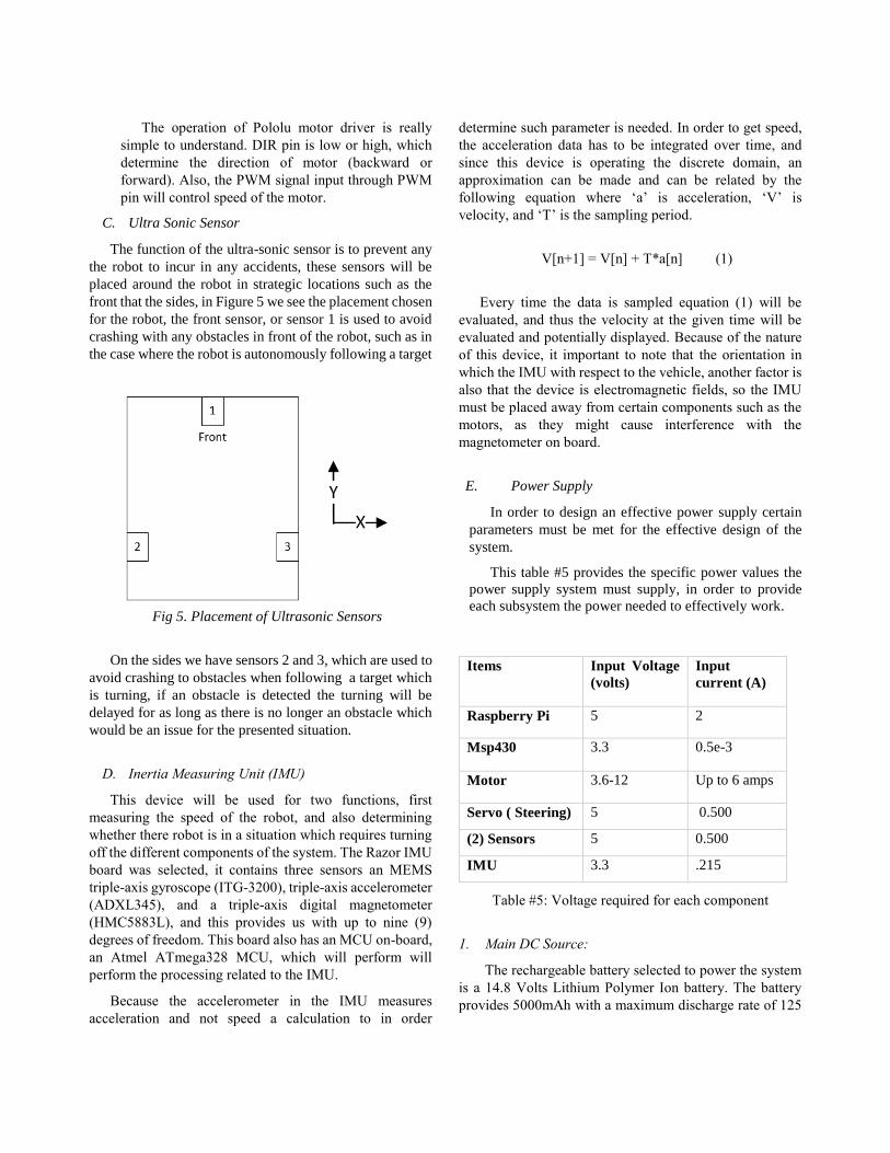
C. Ultra Sonic Sensor
The function of the ultra-sonic sensor is to prevent any
the robot to incur in any accidents, these sensors will be
placed around the robot in strategic locations such as the
front that the sides, in Figure 5 we see the placement chosen
for the robot, the front sensor, or sensor 1 is used to avoid
crashing with any obstacles in front of the robot, such as in
the case where the robot is autonomously following a target
Fig 5. Placement of Ultrasonic Sensors
On the sides we have sensors 2 and 3, which are used to
avoid crashing to obstacles when following a target which
is turning, if an obstacle is detected the turning will be
delayed for as long as there is no longer an obstacle which
would be an issue for the presented situation.
D. Inertia Measuring Unit (IMU)
This device will be used for two functions, first
measuring the speed of the robot, and also determining
whether there robot is in a situation which requires turning
off the different components of the system. The Razor IMU
board was selected, it contains three sensors an MEMS
[6] Texas Instrument, TPS54525 Voltage Regulator Webpage: http://www.ti.com/lit/ds/symlink/tps54525.pdf
Khanh Le, a senior student of Electrical Engineering Department at University of Central Florida, is going to graduate in Spring 2015 semester. He will start working as Quality Engineer in Failure Analysis position with Texas Instrument right after his graduation. He is
planning in pursuing a higher degree in Electrical Engineering in the future.
Victor Hernandez Salomon is graduating with a Bachelor
of Science in Electrical
Engineering from the
University of Central Florida,
upon graduation he will join a
major company in the
Semiconductor industry. His
research interest include
biomedical applications for
analog devices. He is
currently a member Eta Kappa Nu and IEEE.
Bryan Diaz, a senior Electrical
Engineering student at the
University of Central Florida.
Currently a member of IEEE
and SHPE Organizations. After
graduation, he will pursue a
Master’s degree in Electrical
Engineering.
Luis Sosa, a senior Computer
Engineering student at the
University of Central Florida.
Currently Luis is doing an
internship with Lockheed
Martin as a software engineer.
Upon graduation Luis will be
working with Lockheed
Martin as a full time software
engineer. Luis’s areas of interest are machine learning