86
AD-AI44 812 NATIONAL PROGRAM FOR INSPECTION OF NON-FEDERAL DAMS I BLADENS RIVER DAM (CT, A(U) CORPS OF ENGINEERS WALTHAM MA NEW ENGLAND DIV MAR 80 U NC131 L .IIIIE.EIIEEEEE *~T4

AD-AI44 812 NATIONAL PROGRAM FOR INSPECTION OF NON-FEDERAL DAMS I
BLADENS RIVER DAM (CT, A(U) CORPS OF ENGINEERS WALTHAM
MA NEW ENGLAND DIV MAR 80U NC131 L
.IIIIE.EIIEEEEE*~T4
11111- 111 11 1112.2__
111&25IIIJ.L

NAUGATUCK RIVER BASIN
C*4 SEYMOUR, CONNECTICUT
V-
BLADENS RIVER DAM
[ CT 00602
I PHASE I INSPECTION REPORT
I NATIONAL DAM INSPECTION PROGRAM
-3, ~ 2 '~
C=)
I DEPARTMENT OF THE ARMYNEW ENGLAND DIVISION, CORPS OF ENGINEERS
I WALTHAM, MASS. 02154
MARCH 1980 i
0IQ

IINCI ASSTFTEDSECURITY LLASSIFICATION OF TH4IS PAGE (Whan Dae. hnto,od)
REPOT DCUMNTATON AGEREAD INSTRUCTIONSREPOT DCUMNTATON AGEBEFORE COMPLETING FORM
I. REPORT NUMBER 2. GOVT ACCESSION NO. 3. RECIPIENT*$ CATALOG NUMBER
4 TILE wd~ulito)S. TYPE Of' REPORT*S PERIOD COVEREO
Bladns iverDamINSPECTION REPORT
NATIONAL PROGRAM FOR INSPECTION OF NON-FEDERAL 6. PERFORMINGOOR. REPORT NUMBER
DAMS7. AUTHOR(@) S. CONTRACT OR GRANT NUMBER(@)
U.S. ARMY CORPS OF ENGINEERSNEW ENGLAND DIVISION
9. PERFORMING ORGANIZATION NAME AND ADDRESS 1o. PROGRAM EL~zEMN, PROJECT, TASKAREA & WORK UNIT NUMGERS
It. CONTROLLING OFFICE NAME AND ADDRESS 12. REPORT DATS
DEPT. OF THE ARMY, CORPS OF ENGINEERS March 1980NEW ENGLAND DIVISION, NEDED IS. NUMBER OFPAGES
424 TRAPELO ROAD, WALTHAM, MA. 02254 6514. MONITORING AGENCY NAME A ADDRESS(81 differen~t grow Caoinajn 0551.0) 1. SECURITY CLASS. (of this report)
UNCLASSIFIEDIs. OECL ASSI lC ATIONIDOWNGRAOING
IS. DISTRIBUTION STATEMENT (of chi@ Report)
APPROVAL FOR PUBLIC RELEASE: DISTRIBUTION UNLIMITED
17. DISTRIBUTION STATEMENT (of the abstract entered In 11110611 20, It d110ent, (rem A604WO)
IS. SUPPLEMENTARY NOTESCover program reads: Phase I Inspection Report, National Dam Inspection Program;however, the official title of the program is: National Program for Inspection ofNon-Federal Dams; use cover date for date of report.
III. KEY WORDS (Contienue en severe. aide Of nece..mv and iden~tify by bloc* jwmstbo)
DAMS, INSPECTION, DAM SAFETY,
Naugatuck River BasinSeymour, Connecticut
ASISTRACTO (CmIntmo an reverse side 55 n.eseea nd DdmDlt by black Pas"?)
heBladenscRiver Dam consists of an earth emlbankmient section, a concrete buttressspillway section, a rubble concrete gravity spillway section, and an intake structur?for a downstream forebay. The overall length of the dam, is approximately 330 feet anithe maximum height is 20 feet. The dam was classified "Small" in size, with a"Significant"! potential hazard. The range for the Test Flood of a "Small-Significandam is the 100-year flood to the PMF. A test flood equal to the PMF was selecte
eDD I I AM 1 1473 tDITIO01 OF I'NOV SE IS OBS&OL9E

DEPARTMENT OF THE ARMYNEIA ENGLAND DIVISION. CORPS OF ENGINEEPS
424 TRAPELO ROAD
WALTHAM MASSACHUSETTS 0215'-
NLDL , T I P ~
NEDED
Honorable Ella T. GrassoGovernor of the State of ConnecticutState CapitolHartford, Connecticut 0o115
Dear Governor Grasso:
Inclosed is a copy of the Bladens River Dam Phase I Inspection Report,which was prepared under the National Program for Inspection ofNon-Federal Dams. This report is presented for your use and is basedupon a visual inspection, a review of the past performance and a briefhydrological study of the dam. A brief assessment is included at thebeginning of the report. I have approved the report and support thefindings and recommendations described in Section 7 and ask tn.it youkeep me informed of the actions taken to implement them. This follow-upaction is a vitally important part of this program.
A copy of this report has been forwarded to the Department of nnviron-mental Protection, the cooperating agency for the State of Connecticut.In addition, a copy of the report has also been furnished the owner,The Bridgewater Corporation, Huntington, Connecticut 06584.
Copies of this report will be made available to the public, uponrequest, by this oftice under the Freedom of Information Act. In thecase of this report the release oate will be thirty days from the dateof this letter.
1 wish to take this opportunity to thank you and the Department ofEnvironmental Protection for your cooperation in carrying out thisprogram.
Sincerely,
Incl MAX B. SCHEIDERAs stated Colonel, Corps of Engineers
Division Engineer

BLADENS RIVER DAMCT 00602
NAUGATUCK RIVER BASINSEYMOUR, CONNECTICUT
PHASE I INSPECTION REPORTNATIONAL DAM INSPECTION PROGRAM
49-10 MARCH 1980

NATIONAL DAM INSPECTION PROGRAMPHASE I INSPECTION REPORT
IDENTIFICATION NO: CT 00602
NAME OF DAMt Bladens River Dam
TOWN: Seymour
COUNTY AND STATE: New Haven County, Connecticut
STREAM: Bladens River
DATE OF INSPECTION: November 29, 1979
BRIEF ASSESSMENT
The Bladens River Dam consists, from left to right, of an earth
embankment section, a concrete buttress spillway section, a rubble
concrete gravity spillway section, and an intake structure for a
downstream forebay. The overall length of the dam is approximately
330 feet and the maximum height is 20 feet.
The earth embankment is approximately 120 feet long, with a
maximum height of 20 feet, a top width of 8 feet, an upstream slope
of 2 horizontal to 1 vertical, and a downstream slope of 1.7 horizontal
to 1 vertical. The centerline of the embankment is oriented almost
parallel to the river downstream of the spillway. The concrete but-
tress spillway section is 53 feet long and has a maximum height of
17 feet above streambed. The Ambursen-type concrete structure con-
sists of an upstream inclined concrete deck supported by the left
spillway wall, three vertical buttress walls, and the left end of
the gravity spillway section. The left spillway wall consists of
a dry stone masonry wall that separates the downstream river channel
from the earth embankment. The rubble concrete gravity spillway
j section is approximately 32 feet long, with a maximum height above
ii L I -'

streambed of 17 feet. The right spillway wall is a dry stone mas-
onry wall that separates the forebay from the downstream river channel.
The intake structure for the downstream forebay is located at the
right abutment and consists of a wood sluice gate approximately 3'0"
x 3'0", located on the upstream face of a mortared stone masonry
wall that discharges through the wall to a forebay inlet channel with
mortared stone masonry walls. The channel from the forebay to an
abandoned sluiceway is blocked by an earth fill. Flow through the
forebay inlet gate is diverted over an auxiliary spillway in the
right wall of the main spillway to the stream below the main spill-
way. The low level outlet or blowoff gate consists of a manually
operated 36-inch sluice gate located between the two extreme right
buttress walls of the Ambursen-type spillway section.
The dam does not meet the Corps of Engineers criteria for
the "Small" size classification given in the Recommended Guide-
lines for Safety Inspection of Dams. However, for the purpose
of this report the dam was classified "Small" in size, with a
"Significant" potential hazard. The range for the Test Flood
of a "Small-Significant" dam is the 100-Year Flood to one-half
the Probable Maximum Flood (1/2 PMF). A Test Flood equal to
1/2 PMF was selected because of the downstream development.
* Due to the small size of the impoundment, the Test Flood outflow
was assumed to equal the Test Flood inflow of 8,300 cfs and would
* overtop the low point of the dam crest by approximately 3 feet.
The spillway capacity is equal to 940 cfs or 11 percent of the
Test Flood.
Based on the visual inspection and hydraulic/hydrologic inves-
tigation, the dam is considered to be in poor condition. Features
iii

that can effect the future integrity of the dam are: continued deter-
ioration of the concrete in the spillway sections; continued movement
and tilting of the left spillway wall and continued erosion below
the adjacent upstream walls; continued movement of the right spill-
way wall; erosion of the upstream slope of the earth embankment;
further loss of mortar and weakening of the forebay inlet channel
walls; possible internal erosion along root systems of the trees and
vegetation in the masonry walls and in the earth embankment; possible
internal erosion resulting from the seepage at the toe of the earth
embankment; uprooting of large trees on the earth embankment and
right abutment resulting in depressions which reduce the freeboard
of the dam; and, inadequate spillway capacity.
The following items should be investigated by a qualified, reg-
istered engineer and corrected as required: the deteriorating con-
crete spillways; the stability of the left and right spillway walls;
the erosion of the upstream slope of the earth embankment; the deter-
ioration of the forebay inlet channel walls; and, the seepage at the
toe of the earth embankment. In addition, the trees and vegetation
* in the masonry spillway walls and in the earthen embankment should
be removed. The trees should be removed from the earth embankment
by uprooting, and the root zones carefully backfilled as directed by
a qualified, registered engineer. A detailed hydrologic/hydraulic
analysis should be performed to determine the need for and means to
Ii provide additional discharge capacity.
[i
~ &~ZJ~ 'ALI,

The dam should be inspected by a qualified, registered engi-
neer every year. An operations and maintenance manual should be
prepared for the dam and operating facilities, and a formal warn-
ing system put into effect. Should the sediments be removed from
the impoundment, the low level outlet or blowoff gate should be
made operative.
The owner should implement the recommendations as described
herein and in greater detail in Section 7 of the Report within
one year after receipt of this Phase I Inspection Report.
Donald L. Smith, P.E. Roald HaestadProject Engineer President
" {
X4:11
4S4
Ii
e-;- --V*

This Phase I Inspection Report an Bladens River Dam
has been reviewed by the undersigned Reviev Board members. In ouropinion, the reported findings, conclusions, and recommendations areconsistent vith the Recommended Guidelines for Safety Inspection of
Dams, and with good engineering judgment and practice, and is herebysubmitted for approval.
CAPRNEY M. TERZIAN, MEMBERDesign Branch
Engineering Division
RICHARD DIBLONO, MEMBERWater Control Branch
Engineering Division
ARAMAST MAHTESIAN, CHAIRMAN
Geotechnical Enqineering BranchEngineering Division
APPROVAL RECOMMENDED:
#40E a. EnAR iChief, Suainearing Division

PREFACE
This report is prepared under guidance contained in the
Recommended Guidelines for Safety Inspection of Dams, for Phase I
Investigations. Copies of these guidelines may be obtained from
the Office of Chief of Engineers, Washington, D.C. 20314. The
purpose of a Phase I Investigation is to identify expeditiously
those dams which may pose hazards to human life or property. The
assessment of the general condition of the dam is based upon
available data and visual inspections. Detailed investigation,
and analyses involving topographic mapping, subsurface investi-
gations, testing, and detailed computational evaluations are beyond
the scope of a Phase I Investigation; however, the investigation is
intended to identify any need for such studies.
In reviewing this report, it should be realized that the
reported condition of the dam is based on observations of field
conditions at the time of inspection along with data available to
the inspection team. In cases where the reservoir was lowered or
drained prior to inspection, such action, while improving the
stability and safety of the dam, removes the normal load on the
structure and may obscure certain conditions which might otherwise
be detectable if inspected under the normal operating environment
of the structure.
It is important to note that the condition of a dam depends
on numerous and constantly changing internal and external conditions,
and is evolutionary in nature. It would be incorrect to assume that
the present condition of the dam will continue to represent the
vii,
condition of the dam at some point in the future. Only through
continued care and inspection can there be any chance that unsafe
conditions be detected.
Phase I Inspections are not intended to provide detailed
hydrologic and hydraulic analyses. In accordance with the estab-
lished Guidelines, the Spillway Test Flood is based on the estimated
"Probable Maximum Flood" for the region (greatest reasonably possible
storm runoff), or fractions thereof. Because of the magnitude and
rarity of such a storm event, a finding that a spillway will not
pass the test flood should not be interpreted as necessarily
posing a highly inadequate condition. The test flood provides a
measure of relative spillway capacity and serves as an aide in
determining the need for more detailed hydrologic and hydraulic
studies, considering the size of the dam, its general condition
and the downstream damage potential.
The Phase I Investigation does not include an assess7.ent of
the need for fences, gates, no-trespassing signs, repairs to
existing fences and railings and other items which may be needed
to minimize trespass and provide greater security for the facility
and safety of the public. An evaluation of the project for com-
pliance with OSHA rules and regulations is also excluded.
viii

lAP E OF CONTENTS
SECT I ON PAGES
LETTER OF TRANSMITTALi
BRIEF ASSESSMENT ii-v
REVIEW BOARD PAGE vi
PREFACE vii -viii
TABLE OF CONTENTS ix - xi
OVERVIEW PHOTO Xiixiii
LOCATION PLAN
INDEX TO REPORT
DESCRIPTION PAGES
1. PROJECT INFORMATION 1 -9
1.1 GENERAL1
a. AUTHORITY
b. PURPOSE OF INSPECTION1
1.2 DESCRIPTION OF PROJECT 2- 5
a. LOCATION 2
b. DESCRIPTION OF DAM AND APPURTENANCES 2 - 3
C. SIZE CLASSIFICATION 4
d. HAZARD CLASSIFICATION 4
e. OWNERSHIP
f. OPERATOR 5
g. PURPOSE OF DAM
h. DESIGN AND CONSTRUCTION HISTORY 5
1.NORMAL OPERATIONAL PROCEDURE 5
1.3 PERTINENT DATA 5- 9
2. ENGINEERING DATA 10
2.1 DESIGN DATA 10
2.2 CONSTRUCTION DATA 10
2.3 OPERATION DATA 10
2.4 EVALUATION OF DATA 10
ix

DESCRIPTION PAGES
3. VISUAL INSPECTION 11 - 16
3.1 FINDINGS 11 - 15
a. GENERAL 11
b. DAM 11 - 13C. APPURTENANT STRUCTURES 13 - 14
d. RESERVOIR AREA 14e. DOWNSTREAM CHANNEL 15
3.2 EVALUATION 15 - 16
4. OPERATIONAL AND MAINTENANCE PROCEDURES 17
4.1 OPERATIONAL PROCEDURES 17
a. GENERAL 17
b. DESCRIPTION OF ANY WARNING SYSTEM IN EFFECT 17
4.2 MAINTENANCE PROCEDURES 17
a. GENERAL 17
b. OPERATING FACILITIES 17
4.3 EVALUATION 17
s. EVALUATION OF HYDRAULIC/HYDROLOGIC FEATURES 18 - 20
5.1 GENERAL 18
5.2 DESIGN DATA 18
5.3 EXPERIENCE DATA 18
5.4 TEST FLOOD ANALYSIS 19
5.5 DAM FAILURE ANALYSIS 20
EVALUATION OF STRUCTURAL STABILITY 21
6.1 VISUAL OBSERVATION 21
6.2 DESIGN AND CONSTRUCTION DATA 21
6.3 POST-CONSTRUCTION CHANGES 21
6.4 SEISMIC STABILITY 21
/ x

DESCRIPT ION PA GE S
7. ASSESSMENT, RECOMMENDATIONS AND REMEDIAL MEASURES 22 - 25
7.1 DAM ASSESSMENT 22 - 23
a. CONDITION 22 - 23b. ADEQUACY OF INFORMATION 23C. URGENCY 23
7.2 RECOMMENDATIONS 23 - 24
7.3 REMEDIAL MEASURES 24 - 25
a . OPERATION AND MAINTENANCE PROCEDURES 24 - 25
7.4 ALTERNATIVES 25
INDEX TO APPENDIXES
APPENDIX DESCRIPTION PAGES
A INSPECTION CHECKLIST Al - A6
B ENGINEERING DATA PI - E4
C PHOTOGRAPHS Cl - C6
D HYDROLOGIC AND HYDRAULIC COMPUTATIONS Dl - 017
E INFORMATION AS CONTAINED IN THENATIONAL INVENTORY OF DAMS El
Li xi

W
z D~< U-
IL WzzCC
al CD>
UUl
zLi
CD
-JCD
clC-
LLLL
00
(Dz
z
xlii

0/
Se V 11 t/ II
R~ II....DA
U7/
43 >~ I'
'AN //'..-
/ --- -- o s w
~LDCATION PLAN
.. BLADENS RIE ASEMOR CONNECTICUT
ROAL HAET.D IN.NUAUK/UDA E17
/ / ~ ~ ")----

NATIONAL DAM INSPECTION PROGRAMPHASE I INSPECTION REPORT
PROJECT INFORMATION
SECTION 1
1.1 General
a. Authority
Public Law 92-367, August 8, 1972, authorized the Secretary
of the Army, through the Corps of Engineers, to initiate a National
Program of Dam Inspection throughout the United States. The New
England Division of the Corps of Engineers has been assigned the
responsibility of supervising the inspection of dams within the New
England Region. Roald Ilaestad, Inc., has been retained by the New
England Division to inspect and report on selected dams in the State
of Connecticut. Authorization and notice to proceed were issued to
Roald Haestad, Inc. under a letter of November 1, 1979, from
William E. Hodgson, Jr., Colonel, Corps of Engineers. Contract No.
DACW33-80-C-0015 has been assigned by the Corps of Engineers for this
work.
b. Purpose of Inspection
The purposes of the program are to:
1. Perform technical inspection and evaluation of non-
federal damns to identify conditions requiring correction
in a timely manner by non-federal interest.
2. Encourage and prepare the States to quickly initiate
effective damn inspection programs for non-federal dams.
3. To update, verify and complete the National Inventory
of Dams.

1.2 Description of Project
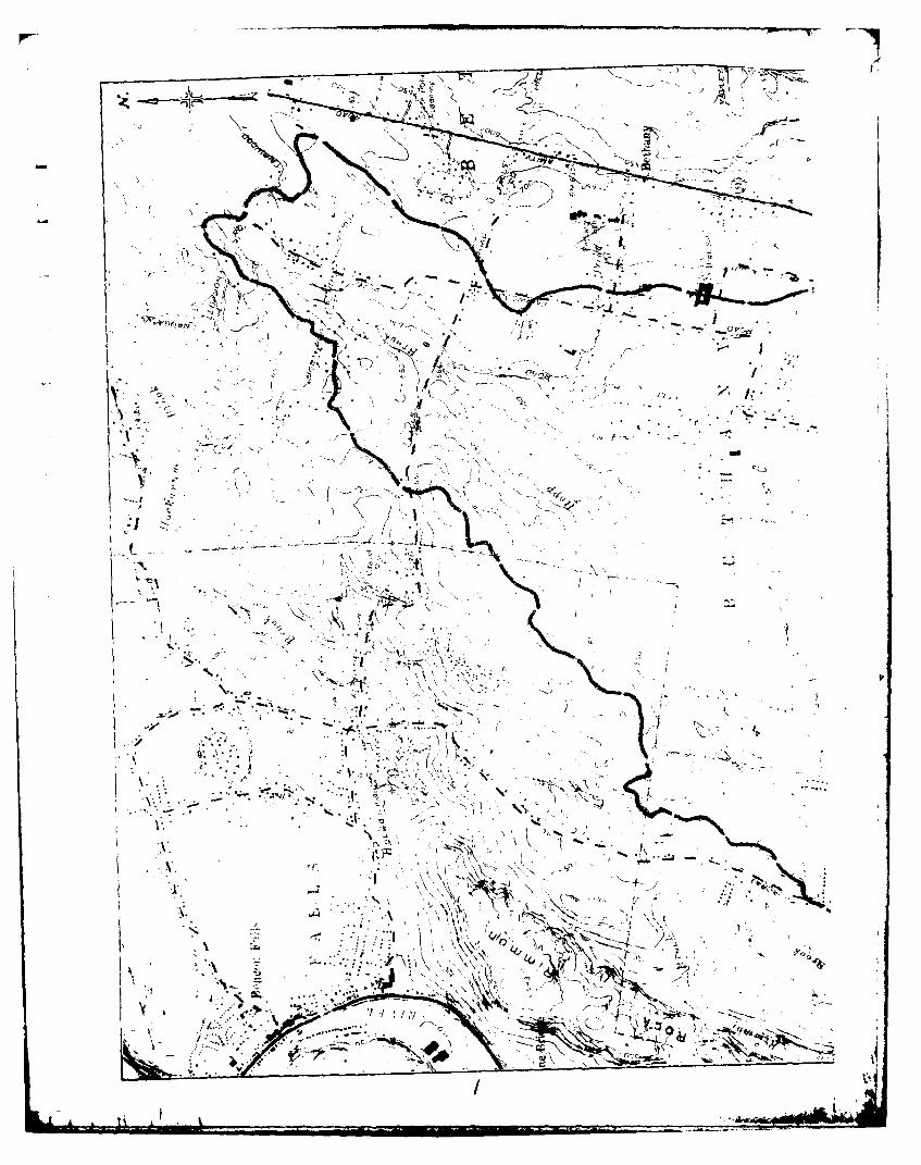
a. Location
The dam is located on Bladens River approximately 3/4 of
a mile east of the confluence with the Naugatuck River just south of
Connecticut Route 67 in the Town of Seymour, Connecticut. The dam
is shown on the Naugatuck Quadrangle Map having coordinates of
latitude N 410 23.8", and longitude W 730 03.5".
b. Descrip tion of-Dam and Appurtenant Structures
The Bladens River Dam consists, from left to right, of an
earth embankment section, a concrete buttress spillway section, a Irubble co:.crete gravity spillway section, and an intake structure
for a downstream forebay. The overall length of the dam is approxi-
mately 330 feet, and the maximum height of the dam above streambed
is 20 feet.
The earth embankment section is approximately 120 feet
long, with a maximum height of 20 feet, a top width of 8 feet, an
upstream slope of 2 horizontal to 1 vertical, and a downstream slope
of 1.7 horizontal to 1 vertical. There is no slope protection on
the upstream slope. A heavy tree growth is present on the upstream
and downstream slopes and on the top of the earth embankment. The
centerline of the embankment is oriented almost parallel to the
river downstream of the spillway.
The concrete buttress section is 53 feet long and has a max-
imum height of 17 feet above streambed. The Ambursen-type concrete
structure consists of an upstream, inclined concrete deck supported
by the left spillway wall, three vertical buttress walls, and the
2 4
I

left end of the gravity spillway section. The spacing between but-
tress walls is 12 feet, the buttress walls are 12 inches thick, and
the upstream concrete deck is on a 450 incline. The left spillway
wall consists of a dry stone masonry wall and separates the earth
embankment from the downstream river channel.
The rubble concrete gravity spillway section is approxi-
mately 32 feet long, with a maximum height of 17 feet above strearr-
bed and an unknown cross-section. The right spillway wall is a dry
stone masonry wall that separates the forebay from the downstr(eam
river channel.
The intake structure for the downstream forebay consists
of a wood sluice gate, approximately 3'-0" x 3'-0", 1 ' K !. ,',,-
upstream face of a mortared stone masonry wall, thit i i >,: 1-s
through the wall to a forebay inlet channel with ,,t if-d it no
masonry walls. The forebay is a :-maIl pIond O -,-,i t h
downstream river channel by the right spillway wall.
The sluiceway from the forebay to a downIst r.>n, ui] irng
is currently not in use. The channel from the foi l'ay to the
sluiceway structure is blocked by an earth fill. Flow through
the forebay intake gate is diverted over in a-uxiliary spillway
to the stream below the main spillway. The auxiliary spillway is
located in the right wall of the main spillway section, and was con-
structed by removing a section of the top of the stone masonry wall.
The low level outlet or blowoff gate consists of a man-
ually operated 36-inch sluice gate located between the second and
third buttress walls from the right.
3
-A -
C. Size Classification - "Small"
According to the Corps of Engineers' Recormmended Guidelines
for Safety Inspection of Dams, a dam is classified as "Small" in size
if the height is between 25 feet and 40 feet, or the dam impounds be-
tween 50 Acre-Feet and 1,000 Acre-Feet. Not included in the inspection
program are dams which are 6 feet or less in height regardless of stor-
age capacity, or which have a storage capacity of 15 Acre-Feet or less
regardless of height. The original inventory listed the structural
height as 34 feet and the maximum storage capacity as 32 Acre-Feet.
The dam as field surveyed has a maximum height of 20 feet and a max-
imum storage capacity of 16 Acre-Feet. Therefore, the dam does not
meet the Corps of Engineers' requirements for a "Small" dam. However,
for the purpose of this report the dam was classified as "Small".
d. Hazard Classification - "Significant"
Based on the Corps of Engineers' Recommended Guidelines for
Safety_ Inspection of Dams, the hazard classification for the dam is
"Significant". A dam failure could result in the loss of a few lives
and an economic loss due to the downstream flooding.
A house and one factory are located approximately 400 feet
downstream of the dam. The depth of flow in this area prior to dam
breach is 3.5 feet above river bed based on a spillway capacity of 940
cfs. The flow in this area due to the dam breach is 9,500 cfs equi-
valent to a depth of flow of 14 feet, or 2 feet above the factory floor
and 6 feet above the cellar of the house. At another factory complex
1,400 feet further downstream, the water levels would increase from 4
feet above the river bed before dam breach to 10.5 feet, or 2 feet deep
in the factories, after dam breach.
4
'4- ' .. . " . .' ' " ..-

e. Own-ershjp
Former Owner: The Seymour Paper Mill
Present Owner: The Bridgewater Corporation303 Isinglass RoadHuntington, Connecticut 06584(203) 929-8588Harold Gorman, P.E., President
f. Operator Michael Gorman (203) 929-8588The Bridgewater Corporation303 Isinglass RoadHuntington, Connecticut 06584
At the present time the dam serves no useful purpose.
The owner is currently investigating the feasibility of utilizing
the dam for hydroelectric purposes.
h. Design -and Construction History
There is no information available on the design and con-
struction of the dam. The owner believes that the stone masonry
portion of the dam and the intake gate to the forebay were con-
structed around 1845. A date scored into the concrete portion
of the spillway indicates that construction took place in 1906.
i. Normal Operational Procedures
As the dam is presently not in use, there are no normal
operational procedures.
1.3 Pertinent Data
a. Drainage Area
The drainage area consists of 10.1 square miles of wooded,
"rolling" terrain, with scattered residential development.
b. Discharge at Damsite
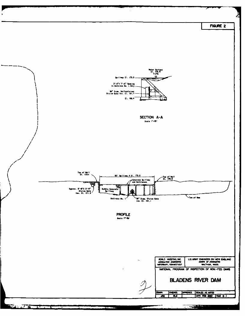
Discharge at the damsite is over an 85-foot long concrete
overflow spillway. A 3'-0" x 3'-0" intake gate is stuck in the
open position and allows water to flow into a forebay, where it
T"ME&

discharges over an auxiliary spillway. A 36-inch low level outlet
or blowoff sluice gate located in the spillway section is stuck in
the closed position.
The maximum known flood since 1973 occurred in January,
1979 when a flow of approximately 18 inches over the spillway was
observed.
1. Outlet Works (conduits) Size: 36 inch*
Invert Elevation: 161.1
Discharge Capacity: 140 cfs
2. Maximum Known Flood at Damsite: 450 cfs (Jan. '79)
(since 1973)3. Ungated Spillway Capacity
at Top of Dam: 940 cfsElevation: 177.5
4. Ungated Spillway Capacityat Test Flood Elevation: 4,050 cfsElevation: 181.6
5. Gated Spillway Caipacityat Normal Pool Elevation: N/AElevation: N/A
6. Gated Spillway Capacityat Test Flood Elevation: N/AElevation: N/A
7. Total Spillway Capacityat Test Flood Elevation: 4,050 cfsElevation: 181.6
8. Total Project Dischargeat Top of Dam: 940 cfsElevation: 177.5
9. Total Project Dischargeat Test Flood Elevation: 8,350 cfsElevation: 181.6
*Inoperative
4o6

c. Elevation - Feet Above Mean Sea Level_(NGVD)
1. Streambed at Toe of Dam: 158
2. Bottom of Cutoff: Unknown
3. Maximum Tailwater: N/A
4. Recreation Pool: N/A
5. Full Flood Control Pool: N/A
6. Spillway Crest: 175
7. Design Surcharge - Original Design: Unknown
8. Top of Dam: 178.6
9. Test Flood Surcharge: 181.6
d. Reservoir - Length in Feet
1. Normal Pool: 400 feet
2. Flood Control Pool: N/A
3. Spillway Crest Pool: 400 feet
4. Top of Dam: 600 feet
5. Test Flood Pool: 1,100 feet
e. Storage - Acre-feet
1. Normal Pool: 13 Acre-Feet
2. Flood Control Pool: N/A
3. Spillway Crest Pool: 13 Acre-Feet
4. Top of Dam: lE Acre-Feet
5. Test Flood Pool: 31 Acre-Feet
f. Reservoir Surface - Acres
1. Normal Pool: 1.3 Acres
2. Flood-Control Pool: N/A
3. Spillway Crest: 1.3 Acres
4. Test Flood Pool: 4.1 Acres
5. Top of Dam: 1.3 Acres
-s

g. Dam
1. Type: 120 ft. Earth Embankment
53 ft. Ambursen-type buttressoverflow32 ft. rubble concrete overflow
2. Length: 330 ft. (including intake struc-ture for downstream factory)
3. Height: 20 feet
4. Top Width: 8 ft. (earth embankment)
5. Side Slopes: 2 Hor. to 1 ver. - upstream(earth embankment) 1.7 Hor. to 1 ver. - down-
stream
6. Zoning: Unknown
7. Tmpervious Core: Unknown
8. Cutoff: Unknown
9. Grout Curtain: Unknown
10. Other:
h. Diversion and Regulating Tunnel - N/A
8J

i. S -]way
1. Type: Rubble concrete gravity cv' -
flow(32 ft.), Amburs-n-t'pebut tr(ss ovecrflow (53 ft.)
2. Length of Wier: 85 f (et
3. Crest Elevationwith Flashboards: N/Awithout Flashboards: 175
4. Gates: N/A
5. Upstream Channel: N/A
6. Downstream Channel: Natural strcuobd of Filite-nsRiver
7. General: Buttress wall spacing 12 ft.;wall thickness 12 in.
j. Regulating Outlets
1. Invert: 161.1
2. Size: 36-inch
3. Description: 36-inch conduit through inclinedslab of buttress spillway section,with downstream sluice gate
4. Control Mechanism: Manually operated from insidecompartment of buttress spillwaysection
5. Other: Impoundment is presently filledwith silt and gate is inoperative

ENGINEERING DATA
SECTION 2
2.1 Design Data
There was no design data available for review.
2.2 Construction Data
There was no information available on the construction of the
dam. The owner believes the stone masonry section near the int-ake
gate to the forebay was constructed around 1845. A date etched
into the concrete portion of the spillway indicates construction
in 1906.
2.3 OLeration Data
Since 1973 the maximum known flow over the spillway occurred
in January 1979 when a flow of approximately 18 inches over the
spillway was observed.
2.4 Evaluation of Data
a. Availability
There was no design or construction data available from
either the State of Connecticut, Department of Environmental Pro-
tection, the owner, or the Town of Seymour.
b. Adequacy
As no design or construction data was available, the assess-
ment of the dam was based on the visual inspection, past performance
history and hydraulic and hydrologic calculations.
10

VI SUAL INtI.I'ECT ION
SECTION 3
3.1 F-in d in qs
a. General
The visual inspection of the dam was conducted on Novem-
ber 29,1979. The inspection t eam was ahcerpan ed by Mr. Michael
German of the Bridgewater Corporation, the owner of the dam.
Approximately 0.1 feet of water was flowing over the spillway at
the time of the inspection. Water was also flowing over the aux-
iliary spillway of the forebay. At the time of the inspection
the dam was judged to be in poor condition.
The dam consists, from left to right, of an earth embank-
ment section, Photo 1; a concrete spillway section, Photo 2; and
an intake structure for a downstream foreLay.
b. Dam
S,]] ay S tion
The overflow spillway has a total length of 85 feet. The
left section of the spillway is a 53-foot long Ambursen-type con-
crete buttress structure, and the right section is a 32-foot long
rubble concrete gravity structure, Photo 2. The Ambursen-type
spillway section is composed of an upstream, inclined concrete deck
supported by the left spillway wall, three vertical buttress walls,
and the left end of the gravity spillway section. Thus, from down-
stream, one can observe four open compartments under the concrete
deck, Photo 2. The downstream face of the gravity section appears
to consist of rubble concrete which may have been faced with gun-
ite, Photo 2.
Lw
PI
Significant concrete deterioration was observed along the
entire length of the spillway crest of both sections, Photos 2 and
3. Areas of particularly severe concrete deterioration of the
spillway crest were observed above the concrete buttress walls,
Photos 3 and 4, and at the left spillway wall, Photos 5 and 6. At
the left spillway wall the deterioration was so severe that water
was flowing around the edgje of the spillway lip as shown in Photo 5.
In the buttress spillway sections, significant concrete deterioration
was observed at the tops and bases of the buttresses, Photos 3 and 4.
This deterioration was most severe at the top of the rightmost but-
tress where reinforcing bars were exposed in several places and where
there was a gap between the concrete at the top of the buttress and
at the bottom of the downstream end of the deck, Photo 2; and at the
base of the center buttress where the downstream end of the buttress
wall was undermined. The conditions of the undlerside of the con-
crete deck varied from good, with minor efflorescence in the far
right compartment, to poor, with deteriorated concrete, exposed
reinforcing steel and seepage in the loft compartment, Photo 4.
In the gravity spillway section some concrete deteriora-
tion was observed on the downstream face, as shown in Photo 2.
The left spillway wall is a dry stone masonry wall, as shown
in Photo 7. Past movement of the left spillway wall was indicated
by 1) generally open joints between the blocks in the wall, 2) a
vertical crack in the stone masonry, Photo 7, 3) tilting of the top
of the wall toward the river, Photo 7, and 4) separation between
the upstream end of the wall and the edge of the spillway, Photos
5 and 6. Some vegetation was observed growing out of the left
12
?i l - -

spillway wall. Some evidence of seepage in the form of rust staining
on the masonry was observed at the base of the wall, n1-wnstrcim of
the spillway.
To the left of the spillway there is an upstream wall which
is undermined to distances up to 12 inches behind the face of the
wall, as shown in Photo 6. The concrete facing on the wall appears
to have been added after previous downstrem movements of the wall,
Photo 5.
The right spillway wall is a dry stone masonry wall and
has an opening which constitutes the auxiliary spillway, Photo 8.
Past movement of the wall is suggested by the generally open nature
of the joints between the blocks in the wall, Photo 8. Some vege-
tation was observed growing out of the right spillway wall.
Earth Embankment Section
The earth embankment section of the dam is approximately
120 feet long and is located between the left spillway wall and the
left abutment. The centerline of the e-bank.ent is oriented al7ost
parallel to the stream channel downstream of the spillway. Heavy
tree growth was observed on the crest and the upstream and downstream
slopes of the embankment, Photo 1. On the upstream slope a nearly
vertical scarp exists at the upstream edge of the crest. Several
large trees were observed growing out of this scarp, Photo 1. Some
seepage with rust staining was observed at the toe of the downstream
slope.
C. Appurtenant Structures
The appurtenant structures consist of 1) a forebay for an
abandoned sluiceway and 2) a low level outlet or blowoff gate in the
spillway section of the dam.
13
-L ..-

The forebay is located to the right of the right spillway
wall and contains an inlet channel and cate structure and an aux-
iliary overflow spillway. The inlet gate is reported to be a wood
gjate stuck in the open position. The channel from the forebay to
the abandoned sluiceway is blocked by an earth fill and the flow
through the inlet gate is diverted over the auxiliary spillway to
the stream channel below the main spillway.
The forebay inlet channel is located downstream of the in-
let gate and has mortared stone masonry walls, as shown in Photo 9.
In many of the joints the mortar was missing or badly deteriorated.
Three trees were observed growing out of the downstream end of the
right wall of the inlet channel, Photo 9.
The auxiliary spillway is located in the right wall of the
spillway section of the dam and was constructed hy removing a sec-
tion of the top of the stone masonry wall, Photo 8.
The low level outlet or blowoff gate is a 36-inch diameter
sluice gate located in the Ambursen-type buttress spillway section,
Photo 3, and is reported to be stuck in the closed position. Some
leakage was observed at the bottom of the gate.
d. Reservoir Area
Siltation of the reservoir has occurred up to practically
the crest of the spillway, Photo 2, resulting in an earth pressure
loading on the upstream side of both the Ambursen-type spillway and
the gravity spillway.
There are no indications of instability along the edges of
the reservoir in the vicinity of the dam.i14
e. Downstream Channel
The spillway sections of the dam and the auxiliary spill-
way of the forebay discharge into the natural streambed of the
Bladens River. Bedrock outcrops were observed in the streambed at
the right side of the dam, as shown in Photo 10.
3.2 Evaluation
Based on the visual inspection the dam is judged to be in poor
condition. The following conditions could effect the integrity of
the dam:
1. Continuation of the concrete deterioration in both spill-
way sections and the increased load 3ue to reservoir silta-
tion could lead to a structural failure of the dam.
2. Continued movement and tilting of the left spillway wall
and erosion below the adjacent upstream wall could result
in partial or complete failure of this wall which could
produce a dam breach.
3. Continued movement of the right spillway wall could result
in partial or complete failure of this wall which could
produce a breach in the dam.
4. Continued erosion of the upstream slope of the earth
embankment section of the dam could breach the dam.
5. Continued loss of mortar and resultant weakening of the
forebay inlet walls could cause failure of those walls
which could lead to erosion around the inlet gate.
6. The root system of the trees and vegetation in the masonry
spillway walls, forebay inlet walls and in the earth em-
bankment section of the dam could provide channels for the
future development of internal erosion.
15

7. The seepage at the toe of the earth embankment section of
the dam could in the future produce internal erosion of
the dam.
8. The large trees at the right abutment and the earth em-
Lkankment could uproot during a storm, resulting in a de-
pression which would reduce the freeboard of the dam.
16
,

OPERATIONAL AND MAINTENANCE PROCEDURES
SECTION 4
4.1 Operational Procedures
a. General
At the present time the dam serves no useful purpose.
Therefore no operational procedures are in effect. The current
owner is investigating the feasibility of utilizing the dam for
nydroelectric purposes.
b. Description of Any Warning System In Effect
There is no formal warning system in effect.
4.2 Maintenance Procedures
a. General
The owner has recently removed trees from portions of the
dam. The auxiliary spillway for the forebay was lowered by removing
stones from the wall to accommodate low stream flows.
b. Operating Facilities
An earth fill has been placed in front of the intake to
the sluiceway leading to the forebay. The owner has tried unsuc-
cessfully to open the low level outlet.
4.3 Evaluation
The present operational and maintenance procedures are in-
adequate. An operations and maintenance manual for the dam and
operating facilities should be prepared. The dam should be in-
spected annually by a qualified, registered engineer.
A formal warning system should be put into effect and should
include monitoring of the dam during heavy rains, and procedures
for notifying downstream authorities.
.* 17
- =I

EVALUATION DF HYDRAULIC/HYDROLOGIC FEATURES
SECTION 5
5.1 General
The Bladens River Dam has a tributary watershed of 10.1 square
miles of wooded, "rolling" terrain with scattered residential devel-
opment.
The dam has an 85-foot long spillway consisting of a concrete
gravity section and an Ambursen Buttress section. The average
crest height of the dam is 3 feet above spillway with a low point
in the earth embankment, 2.5 feet above spillway. The spillway
has a capacity of 940 cfs before overtopping the ,tmbankment.
A wooden sluice gate at the right abutment is stuck partially
open. This allows water to enter the forebay, where it is diverted
back to the river channel via an auxiliary spillway. The gate is
approximately 3'-0" x 3'-0". The gate can discharge all of the dry
weather flows during most of the summer. A 36-inch cast iron low
level outlet or blowoff gate is located in the buttress s(ction of
the dam. The owner reported the gate to be inoperative.
A 36-inch reinforced concrete pipe used to transport water from
the forebay to the factory below the dam. The channel from the fore-
bay to the intake for the sluiceway is blocked by an earth fill.
5.2 Design Data
No information could be found relating to the design of the
dam or the spillway.
5.3 Experience Data
The highest water level observed by the present owner occurred
in January 1979 when a depth of 18-inches was recorded going over
the spillway. These observations date back only to 1973.
18

5.4 Test Flood Analysis
Based on the dam failure analysis, the dam is classified as
"Significant" hazard potential. The 20 foot height and 16 Acre-Feet
storage capacity are below the requirements for even a small dam.
The 16 Acre-Feet storage capacity was calculated assuming the pond
was dredged out. The pond is currently filled with sediment to above
spillway level in many places. For purposes of selectinga Test Flood,
the dam was classified as "Small - Significant". Based on the Corps
of Engineers' Recommended Guidelines for Safety Inspection of Dams,
the spillway Test Flood should be in the range of the 100-Year Flood
to one-half the Probable Maximum Flood (1/2 PMF) depending on the
involved risk.
A Test Flood equal to 1/2 PMF was selected because of the down-
stream development. A peak rate of runoff of 825 cubic feet per second
per square mile (csm) from the guide curve for "rolling" terrain sup-
plied by the Corps of Engineers was used along with the watershed area
of 10.1 square miles to arrive at the 1/2 PMF of 8,300 cfs. The ini-
tial water level was assumed at spillway level. The impoundment is too
small to affect the flood peak so that inflow is equal to outflow. The
calculated spillway capacity of 940 cfs before overtopping the low
point of the embankment is equal to 11 percent of the Test Flood. The
low level outlet is inoperative and because of its location under the
buttress section of the dam it cannot be reached in an emergency. The
wood sluice gate is considered to have a negligible capacity compared
to the Test Flood.
The spillway of this dam is judged to be inadequate. Overtopping
of the dam could occur in the future. Further investigations are re-
quired to determine the need for and means to provide additional dis-
charge capacity.
19
5.5 Dam Fail-ure A-nalysis
A dam failure analysis was made using the "Rule of Thumb" gui-
dance provided by the Corps of Engineers. Failure was assumed when
the water level reached the top of the dam.
A breach of the dam would release up to 13,200 cfs into the
stream channel below the dam. It should be noted that a flow of this
magnitude would empty the pond in less than one minute.
The area of prime impact is the factory 400 feet downstream of
the dam and the house across the river from the factory. The factory
is owned by the Bridgewater Corporation, owner of the dam. Water
depth prior to failure would be 3.5 feet above river bed based on a
spil' .ay capacity of 940 cfs. The flood wave at the factory and house
would have a dlepth of over 14 feet and a flow of 9,500 cfs. Water
depth in the factory would be about 2 feet. The house has a finished
basement exposed to the river channel and would be flooded to a depth
of about 6 feet above the cellar floor.
There is another large factory complex about 1,400 feet further
downstream. The flood wave would cause water depths of about 2 feet
in two of the factory buildings. Water levels would be 4 feet above
river bed prior to failure and 10.5 feet at failure. Peak flood
flow would be 3,700 cfs. Below this point the flood wave would be
confined to the river channel.
The dam is classified as "Significant" hazard potential. A dam
failure could result in the loss of a few lives and an economic loss
due to the flooding of the factories.
The dam breach calculations are shown in Appendix D.
20

EVALUATION OF STRUCTURAL STABILITYSECTION 6
6.1 Visual Observations
The tilting and apparent past movements of the left spillway
wall suggest that it may be only marginally stable at present.
Siltation of the reservoir has occurred practically up to the
crest of the spillway resulting in an earth pressure loading on the
upstream side of the spillway sections.
The future integrity of the dam could be affected by continued
deterioration of the concrete spillway sections, continued movement
of the left and right spillway walls, erosion of the upstream slope
of the earth embankment, and possible internal erosion along the
root systems of trees or resulting from seepage.
6.2 Design and Construction Data
There was no design or construction data available.
6.3 Post-Construction Changes
No known post construction changes have been made which might
jeopardize the integrity of the dam.
6.4 Seismic Stability
The dam is located in Seismic Zone I, and in accordance with
the recommended Phase I Inspection Guidelines does not warrant
seismic analysis.
21

ASSFSSMLNT, RECOMMENDATIONS. & REMEDIAL MEASURES
SECTION 7
7.1 Dam Assessment
a. Condition
On the basis of the visual inspection, the dam is judged
to be in poor condition. The future integrity of the dam could be
affected by the following:
1. Continued deterioration of the concrete in the spillway
sections, and the increased load due to reservoir siltation.
2. Continued movement and tilting of the left spillway wall
and continued erosion below the adjacent upstream wall.
3. Continued movement of the right spillway wall.
4. Continued erosion of the upstream slope of the earth
embankment section of the dlam.
5. Further loss of mortar and resultant weakening of the
forebay inlet walls.
6. Possible future internal erosion along root systems of
the trees and vegetation in the masonry spillway walls
and in the earth embankment section of the dam.
7. Possible future internal erosion resulting from the
seepage at the toe of the earth embankment section of the
dam.
8. The large trees at the right abutment and earth embank-
ment could uproot during a storm, resulting in a depression
which would reduce the freeboard of the dam.
The evaluation of Hydraulic/Hydrologic features of the dam in-
dicates that the spillway is capable of passing 11 percent of the
[22 4

Test Flood before overtopping of tle low point of the earth cpmh- 1 nk-
ment occurs. The earth embankment would be overtopped by approxi-
mately 3 feet due to the Test Flood.
b. Adequacy of Information
There was no design and construction information available
and thus the assessment of the condition of the dam is based solely
on the visual inspection and past performance history of the darn.
C. Urgency
The recomnendations presented in Section 7.2 and 7.3
should be carried out within one year after receipt of this report
by the owner.
7.2 Recommendations
The following recoimmendations should be carried out under i-he
direction of a qualified, registered engineer:
1. The deteriorating concrete spillways should be examined
and necessary repairs made. Consideration should be given
to the increased loading due to reservoir siltation.
2. The left spillway wall should be investigated and remedial
measures to increase the stability of the wall and prevunt
undermining of the adjacent upstream wall should be designed
and constructed.
3. The right spillway wall should be investigated and remedial
measures to retard the movements of the wall should be
designed and constructed.
4. The erosion of the upstream slope of the earth embankment
section of the dam should be investigated and appropriate
slope protection should be designed and constructed.
23! 2 .

5. The forebay inlet walls should be investigated and rr°dial
measures performed, as necessary.
6. The trees and vegetation in the masonry spillway walls and
in the earth embankment section of the dam should be removed.
The trees should be removed by uprooting and the root zones
carefully backfilled with selected soil, placed as directed
by the engineer.
7. The seepage at the toe of the earth embankment section of
the dam should be investigated and seepage control measures
should be designed and constructed, as necessary.
8. A detailed hydrologic/hydraulic analysis should be performed
to determine the need for and means to provide additional
discharge capacity.
7.3 Remedial Measures
a. Operation and Maintenance Procedures
1. Technical inspections by qualified, registered en3ineers
should be made every year.
2. A formal operations and maintenance manual for the dam
and operating facilities should be prepared.
3. A formal warning system should be put into effect and
should include monitoring of the dam during heavy rains
and procedures for notifying downstream authorities in
rthe event of an emergency.
4. The large tree at the right abutment should be removed
to eliminate the possibility of uprooting. If the fore-
bay is excavated in the future, the removal of the tree
stump should be investigated to determine if the root
system could lead to possible internal erosion.
24

5. The low level outlet or blowoff should be Made op(rative
when sediments are removed from the impoundment.
7.4 Alternatives
An alternative to the above rt-,:Londtions is to rjmove the
dam.
25

APPENDIX A
VISUAL CHECK LIST WITH COMMENTS

VISUAL INSPECTION CHECK LIST+ PARTY ORGANI ZATI ON
PROJECT.--- Iia ki( 1 ____ _
DATE: 11/29/79 TIME: 8:30 a.m. WEATHER: C]ear, Cold
W.S. ELEVATION: 175.1 _U.S. N/A DN.S0.1 above spillway
PARTY DISCIPLINE
I Donald L. Smith, P.E. - Roald Haestad, Inc. Civil/Hydrologist
2. Ronald G. Litke, P.E. - Foald Haestad, Inc. Civil Engineer
Ceotechni cal3. Gonzalo Castro, Ph.D., P.E. - Engineers, Inc. Ceotechnical Engineer
Geotechnical
4 John W. France, P.E. - Engineers, Inc. Geotechnical Engineer
5. Michael Gorman - Bridgewater Corporation Owner's representative
6 .
INSPECTED
PROJECT FEATURE BY REMARKS
1 Spillway Sections of Dam GC,JWF Deteriorated concreteSpillway Weir, GC,JWF
2 .Outlet Works - Appr. & Disch. RGL,DLS Deteriorated concrete
(Forebay) Intake Channel GC,JWF Fair - mortar deteriorated
3.Outlet Works - & Structure RGL,DLS or missino in stone Fjaonrv
(Forebay) Outlet Structure GCJWF
4. Outlet Works - & Channel RGL,DLS Stone mas-onry - teriorated
Irreoular with trees on em-
5. Dam Embankment CC,JWF bankrment, uj stream erosion
7.
8.
9.
10.
11.
12.
A-1
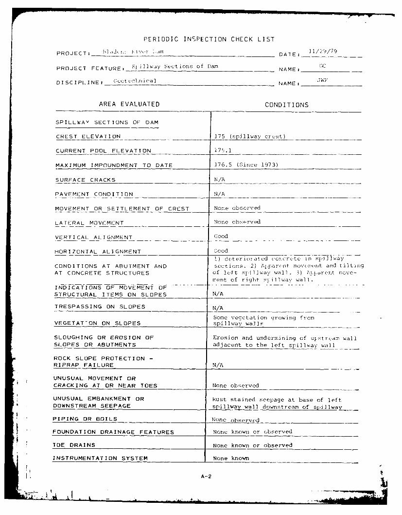
PERIODIC INSPECTION CHECK LIST
PROJECT: h]/L- r iv -Am DATE: I1/29/79
PROJECT FEATURE: S1 ilway Sections of Dam NAMEZ G_
DISCIPLINE: Guot echInica NAME: ITJN_ _
AREA EVALUATED CONDITIONS
SPILLWAY SECTIONS OF DAM
CREST ELEVATION 175 (spillway crest)
CURRENT POOL ELEVATION 175.1
MAXIMUM IMPOUNDMENT TO DATE 176.5 (Since 1973)
SURFACE CRACKS N/A
PAVEMENT CONDITION N/A
MOVEMENT OR SETTLEMENT OF CREST None observed
LATERAL MOVEMENT None observed
VERTICAL ALIGNMENT Good
HORIZONTAL ALIGNMENT Good
1) deteriorated coincrete in slil.way
CONDITIONS AT ABUTMENT AND sections. 2) Apiarot move-ment and tiltingAT CONCRETE STRUCTURES of left spillway wall. 3) Aj--,rent move-
ment of right sillway wall.I-NDICATIONS OF MOVEMENT OF ....... ... .
STRUCTURAL ITEMS ON SLOPES N/A
TRESPASSING ON SLOPES N/A
Some vegetation growing fromVEGETAT'ON ON SLOPES spillway walls
SLOUGHING OR EROSION OF Erosion and undermining of ustr(,am wall
SLOPES OR ABUTMENTS adjacent to the left spillway wall
ROCK SLOPE PROTECTION -
RIPRAP FAILURE N/A
UNUSUAL MOVEMENT OR
CRACKING AT OR NEAR TOES None observed
UNUSUAL EMBANKMENT OR Rust stained seepage at base of leftDOWNSTREAM SEEPAGE sliway wall downstream of spjjlway
PIPING OR BOILS None observed
FOUNDATION DRAINAGE FEATURES None known or observed
* TOE DRAINS None known or observed
INSTRUMENTATION SYSTEM None known
A-2
1L
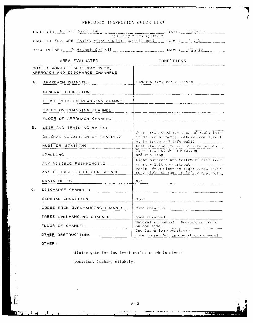
PERIODIC INSPECTION CHECK LIST
PROJECT : 11,-n-1'; FI'v I ____ __ DATE:--- 7?;j ili a 11 V1, W r , Al ; 1:
PROJE CT FE AT URE: Out I (t Wi ,ks Di N A~~jaq MEane u__ N..E:
DISCIPLINE:--(tincI/iil__ NAME: __ ' .1 1
AREA EVALUATED CO ND IT ION S
OUTLET WORKS - SPILLWAY WEIR,APPROACH AND DISCHARGE CHANNELS
A. APPROACH CHANNEL: Unleir wtt-xr, niot ciAs.-ived
GENERAL CONDITION_____
LOOSE ROCK OVERHANGINGCHNE ________________
TREES OVERHANGING CHANNEL___
FLOOR OF APPROACH CHANNEL
B. WEIR AND TRAINING WALLS:
gjre aI d quod (, ort ion of ri qht b~ut -GENERAL CONDITION OF CONCRETE t rc uss C (,I-, a Itmer'?t ) , others poo(.r (c res-t
at hutt-c ss and lecft wall)RUST OR ST AIN ING FBus t -t a in i rq !y evet at e(me rnt5
Manyzarras of deter -orjt ionSPALL ING ______and s:Ialling
Right buttress and bottom of d-..c-k i
ANY VISIBLE REINFORCING crest -left cnm-rartment
Var i es from m inor i n r i ylt I!. t 0 ~ANY SEEPAGE OR EFFLORESCENCE t o visIle i oauc in lot l. S
DRAIN HOLES N/A
C. DISCHARGE CHANNEL:
GENERAL CONDITION c;ood
LOOSE ROCK OVERHANGING CHANNEL None observed
TREES OVERHANGING CHANNEL None observed-_____
Natural stieimbed. Redrock outcroysFLOOR OF CHANNEL on one side.
one large log downstream.OTHER OBSTRUCTIONS Some loose rock in downstream channel
OTHER:
Sluice gate for low level outlet stuck in closed
position, leaking slightly.
IA-3

PERIODIC INSPECTION CHECK LIST
PROJECT: F1ddtn Riv,.rn __m_ DATE: ] / q/79
Intake Channel
PROJECT FEATURE: C)-itlet Works - and Structure (Forebay)NAME: GC,W-
DISCIPLINE: Geotechnical/Civil NAME: RGL,DLS
AREA EVALUATED CONDITIONS
OUTLET WORKS - INTAKE
CHANNEL AND INTAKE STRUCTURE
Forebay approach channel locatedA. APPROACH CHANNEL: downstream of inlet gate
Stone masonry walls with missing
SLOPE CONDITIONS and dceteriorated mortar
BOTTOM CONDITIONS Not observed, under water
ROCK SLIDES OR FALLS None obs:erved
LOG BOOM N/A
DEBRIS N/A
CONDITION OF CONCRETE
LINING N/A
DRAINS OR VEEP HOLES
B. INTAKE STRUCTURE:----
Stone masonry walls with miP singCONDITION OF CONCRETE and deteriorated mortar
STOP LOGS AND SLOTS N/A
OTHER:
Intake gate reportedly stuck in open position.
4
I. A-4£
[DER IUDIC 1WbiLCi 1Lb CHECK LIST
PROJECT: laIJrl., kivtI ITa DATE: 11/29/79uutlet S tructure
PROJECT FEATURE: Outlet WorkL, - and Channel (Forbay) NAME: (;"Jwl_
DISCIPLINE: ___o__ nJ_ a/_ vi NAME: RF T,, DLS
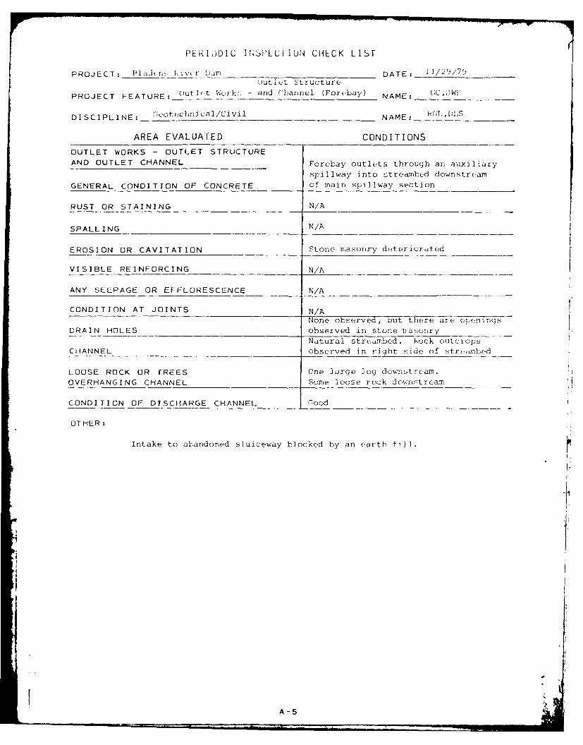
AREA EVALUATED CONDITIONS
OUTLET WORKS - OUTLET STRUCTURE
AND OUTLET CHANNEL Forebay outlets through an auxiliary
spillway into streambed downstream
GENERAL CONDITION OF CONCRETE of main spillway section
RUST OR STAINING N/A
SPALL ING N/A
EROSION OR CAVITATION Stone masonry deteriorated
VISIBLE REINFORCING N/A
ANY SEEPAGE OR EFFLORESCENCE N/A
CONDITION AT JOINTS N/A
None observed, but there are olpenings
DRAIN HOLES observed in stone masonryNatural streambed. Rock outclops
CHANNEL observed in right side of str--ambed
LOOSE ROCK OR TREES One large ]og downstream.OVERHANGING CHANNEL Some loose rock downs-tream
CONDITION OF DISCHARGE CHANNEL Good
OTHER:
Intake to abandoned sluiceway blocked by an earth fill.
A-5 -
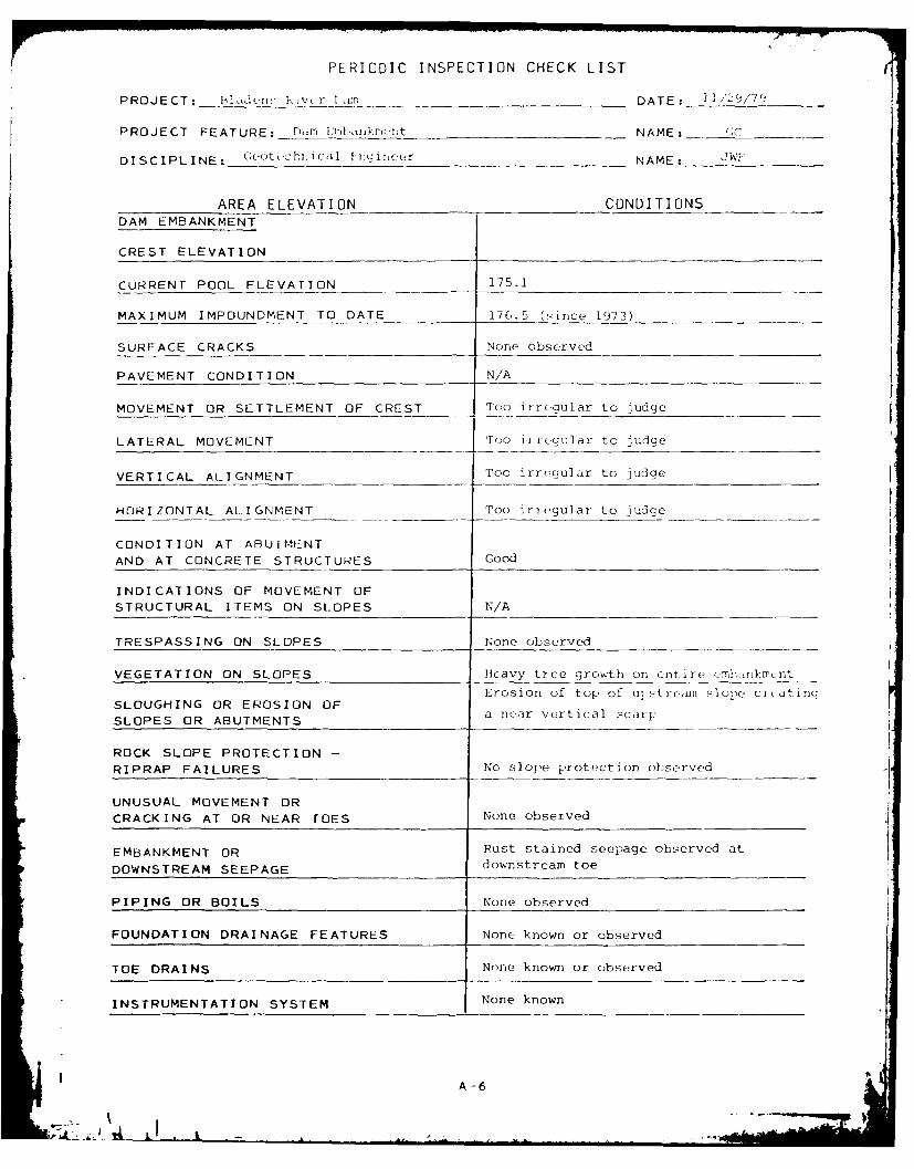
PERIODIC INSPECTION CHECK LIST
PROJECT: I'ldei,, r N tr Iam DATE: I/29//7
PROJECT FEATURE: Da i:5',, (1t NAME: _ _ _
DISCIPLINE: c(.ott,chni cal FnQrine r NAME: JWF'
AREA ELEVATION CONDITIONS
DAM EMBANKMENT
CREST ELEVATION
CURRENT POOL ELEVATION -- 175.1
MAXIMUM IMPOUNDMENT TO DATE 176.5 (r ince 1973)
SURFACE CRACKS None observed
PAVEMENT CONDITION N/A
MOVEMENT OR SETTLEMENT OF CREST Tho irregular to judge
LATERAL MOVEMENT Too i regular to judge
VERTICAL ALIGNMENT Too irregular to judge
HORIZONTAL ALIGNMENT Too iriegular to judge
CONDITION AT ABUTMENTAND AT CONCRETE STRUCTURES Good
INDICATIONS OF MOVEMENT OF
STRUCTURAL ITEMS ON SLOPES N/A
TRESPASSING ON SLOPES None observed
VEGETATION ON SLOPES Heavy tree growth on entire ermn-,ankm(-nt
Erosion of top of ul ;stream slope creatingSLOUGHING OR EROSION OF
SLOPES OR ABUTMENTS a near vertical scarp
ROCK SLOPE PROTECTION -
RIPRAP FAILURES No slope protection ohserved
UNUSUAL MOVEMENT OR
CRACKING AT OR NEAR TOES None observed
EMBANKMENT OR Rust stained seepage observed at
DOWNSTREAM SEEPAGE downstream toe
PIPING OR BOILS None observed
FOUNDATION DRAINAGE FEATURES None known or observed
TOE DRAINS None known or observed
INSTRUMENTATION SYSTEM None known
A-6

APPENDIX B
ENGINEERING DATA

SLADE/
swr RIE
n eI fit Va ( -II* 1' I (ap/x In:ii
I I8011 By 241S 1.4*Owin
For" soilwa Lef Spllalft/We I st/ Itirtia o Noe117oift l. IS Av,*J "'ane'/ if/
. 11"b~t
oncree
"tfor.11. 71. Tooof op o bisoilon/171.9Dan o. 1Ill
[ PLAN
Scl -m
Ittress. only
Sl ic Si* 3e1s t. l dl
sil gt Inv E. 16). 1
SECTION A-A
I scale 1'.20,
To/fWl/vl~ l 7. o fWlAl/l11 l 7.
/rrtereo/l V01 -. ilbeCo
lu. 1res61 l. 1 1l. 171 i. s.fc gaeoooof
I Is,. l. 67..
lii.uln awail WA1.1Il
NI~lONAL PF4OGRAM OF INSPECTION OF NON -FED. DAMS
BLADENS RIVER DAM
OL0 I JAW U SW 1011K8-
7I U 6 -

LIST OF REFERENCES
All references are located at the Department of Environmental
Protection, Office of The Superintendent of Dams, State Office
Building, Hartford, Connecticut 06115.
1. Letter Request to the Connecticut Department of Environ-
mental Protection from First Selectman of the Town of
Seymour, Connecticut, for inspection of the dam, dated
March 4, 1976.
2. Letter Report, "Inspection Report - Dam on the Bladens
River, Seymour - Dam Inventory No. S-4", by Robert E.
Sonnichsen, dated April 30, 1976.
3. Letter from Seymour First Selectman to Connecticut De-
partment of Environmental Protection, indicating ownmer
of dam as Bridgewater Corporation, P.O. Box 2070, Hunting-
ton, Connecticut 06484, dated June 21, 1976.
4. Letter from the Connecticut Department of Environmental
Protection to the Bridgewater Corporation, dated June 30,
1976, requesting an engineering evaluation of the dam and
submission of a report within 60 days.
5. Letter from the Connecticut Department of Environmental
Protection to Bridgewater Corporation, dated November 4,
1976, stating no report had been recieved and that a formal
order would be issued if a report was not received within
two weeks.
B-2

SUGGESTION COMMITTEE SAY: Improve Your Own Condition; Earn CosI and Recogntion: Send in a Suggestion
Inierepartment Message SAVE TIME Ila. ,,,ite.. ,-eia ami a ,tSIC 01rdeparfm 3s '73 $ I[Uie car bon if you feally nced a top) If Jpt'Ar fli,- q r anI 1,"e;570-201 RE v. 3,'73 $1 Alf OF (ON% I( ItL"'
h AMETo - F'{ Il PAL,~
AGE NC ) A!; [ -
k S
NAWI TIiLt ILL F
Fm _ bert E. Sonniehsen ....- er Tntar TE L I ......Fr m AGE NCY AtDRL 5V,
Environmental ProtectionSUBJECI
Inspection Report - Dam on Bladens River, Seymour - Dam Inventory No. S-4
The subject dam has been inspected twice within the last month at therequest of the Town of Seymour.
The structure is partially concrete buttress and partially dry stonemasonry. Portions of the dry stone masonr, have been iunited to give itthe appearance of concrete, but weathering reveals that, in fact, theoriginal masonry exists under the gunite. Original ary stone masonry existsuncovered on both wing walls and on the sluiceway overflow spillway. Thedam's sluiceway has been filled and all water leaking thrcugL the sluicewayentrance gate returns to the river channel by way of the overflow spillway.
The concrete work on the spillway and both abutiments shows sig s ofdeterioration. It a;pears tc be normal weathering. Areas where flow hasbeen concentrated along the base of the southern abutment and some sectionsof the top of the buttress show most severe deterioration. The concrete onthe spillway could not be inspected in more depth than a visual inspectionbecause of the large quantity of flow. Concrete on the south abutment wasin relatively sound condition.
The pond area has been filled with a large quantity of silt. rhedepth of water upstream of the spillway was approximately two feet. I Cesilt appeared to be rather coarse grained gravely sand. No subsurfaceexamination of the silt was performed.
The presence of the silt on the upstream face of the buttress sectionof the dam has certainly increased the loadings on the dam. Generally,design of a structure of this type includes a conservative factor of safetyto compensate for the many unknown factors involved upon construction. Noplans or specifications for design of the particular structure are availableto this office, but it is the opinion of the engineering staff that theincrease in loading due to the presence of the silt blanket on the upstreamface of the buttressSaction of the dam should not surpass the factor ofsafety included in its construction design. Therefore, the spillway sec-tion of this dam is not considered to be in an unsafe condition.
South of the spillway section of the dam, an earth embankment sectionextends approximately 75 feet. The earth embankment section ties into asteep bank at its-end. The embankment wall is -extremely steep sloped I(approximately 1 /I) and has a substantial number of large trees growingfrom it. An investigation of the base of the embankment revealed that itwas saturated and seepage flows existed. Many of.the stones at the baseof the embankment were covered by rust colored iron bacteria which is often
- present in the vicinity-oT earth embankment seepage areas. This earthSAVE TIME: It conveiie,, 6badwvrie reply so sje de on f .i jame sheet.
8-3
, ~ ~ -., .. . . .. .-.. . . . . . ....

e~mr'oa!/~ t~1aeo'.'e to Le tne Ieast 'table sec-I n of: t:.oca:.AlIthoughI the sieepaL-e ELa saturation oi the La.se of' the :vr"- 'odid not ap-pear to placce thie da-m in ii:-ieudlate danger of failure, 1 e c.that at shoculd be repaired by re-inforcing its downistream slope wtLh arelati-vojv pervious fill. The silt dcan , t frorr thje poild ha)CttorT nay t,
suitablec v.aterial for ,hls us-e.
Water ?,csources Unit-
RES 1
B-4

APPENDIX C
PHOTOGRAPHS

LA-
> Z
rL c 0 -V)
a.r - -z =c 0-
-Li 2
IN,
4rrKc
N C14
N ~ o -
N N Lk-1
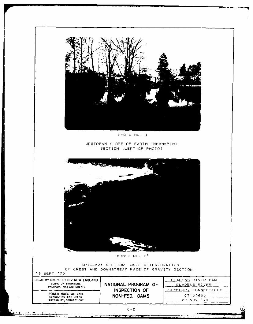
PHOTO NO. 1
UPSTREAM SLOPE OF EARTH EMBANKMENT
SECTION (LEFT OF PHOTO)
PHOTO NO. 2*
SPILLWAY SECTION. NOTE DETERIORATIONOF CREST AND DOWNSTREAM FACE OF GRAVITY SECTION.
*9 SEPT '79
US ARMY ENGINEER DIV NEW ENGLAND BLADENS RIVER DAMCORPS OF ENGINEERS NATIONAL PORMOF BLADENS RIVER
WALTHAM, MASSACHUSETTS PO R M__________________INSPECTION OF SEYMOUR, C NNECTICUT
ROALD HAESTAD, INC. NNFD ASC 00CONSULTING ENGINEERS NNFD ASC 00
WATERBURY, CONNECTICUT 29 NOV '79_ j
*C -2

PHOTO NO. 3
LOW LEVEL OUTLET OR BLOWOFF IN AMBURSEN-TYPE
BUTTRESS SECTION. NOTE CONCRETE DETERIORATION
PHOTO NO. 4
DETERIORATED CONCRETE AT LEFT END OF AMBURSEN-
TYPE BUTTRESS SECTION. NOTE EXPOSED REINFORCING STEEL
US ARMY ENGINEER DIV NEW ENGLAND BLADENS RIVER DAM
CORPS OF ENGINEERS NATIONAL PROGRAM OF BLADENS RIVERINSPECTION OF SEYMOUR, CONNECTICUT
ROALD HAESTAD, INC. NON-FED. DAMS CT 00602CONSULTING ENGINEERSNO -E .D M
ATEROURY, CONNECTICUT 9 SEPT ' 79
C-3

PHOTO NO. 5
WATER FLOWING AROUND LEFT END
OF SPILLWAY WALL. NOTE HOW UP-
STREAM CONCRETE FACE ON WALLHAS BEEN ADDED TO MASONRY WALL
PHOTO NO. 6
UPSTREAM WALL ADJA-
CENT TO LEFT SPILL-
WAY WALL AND SPILL-WAY CREST. NOTE UN-
UNDERMINING OFUPSTREAM WALL
U SARMY ENGINEER DIV NEW ENGLAND BLADENS RIVER DAM
CORPS OF ENGINEERS NATIONAL PROGRAM OF BLADENS RIVERWALTHAM, ASSACHUSETT INSPECTION OF SEYMOUR, CONNECTICUTROALD HAESTAD, INC. NCT 00602CONSULTING ENGINEERS NON-FED. DAMSWATERBURY, CONNECTICUT C 29 NOV '79
I" C-4

PHOTO NO. 7
LEFT SPILLWAY WALL FROM
DOWNSTREAM. NOTE VERTICAL
CRACK IN MASONRY WALL AND
TILTING OF WALL.
PHOTO NO. 8
RIGHT SPILLWAY WALL
DOWNSTREAM OF MAIN
SPILLWAY, INCLUDING
AUXILIARY SPILLWAY
FROM FOREBAY.
US ARMY ENGINEER DIV NEW ENGLAND BLADENS RIVER DAM
WALTHAM MASSECHUNEES NATIONAL PROGRAM OF BLADENS RIVER
WALHAM MASACUSETSINSPECTION OF SEYMOUR, CONNECTICUT
ROALD HAESTAD, INC. NNFDDASCT 00602CONSULTING ENGINEERS 29-FD NAMS
WATERBURY, CONNECTICUT 2NO 79
C- 5
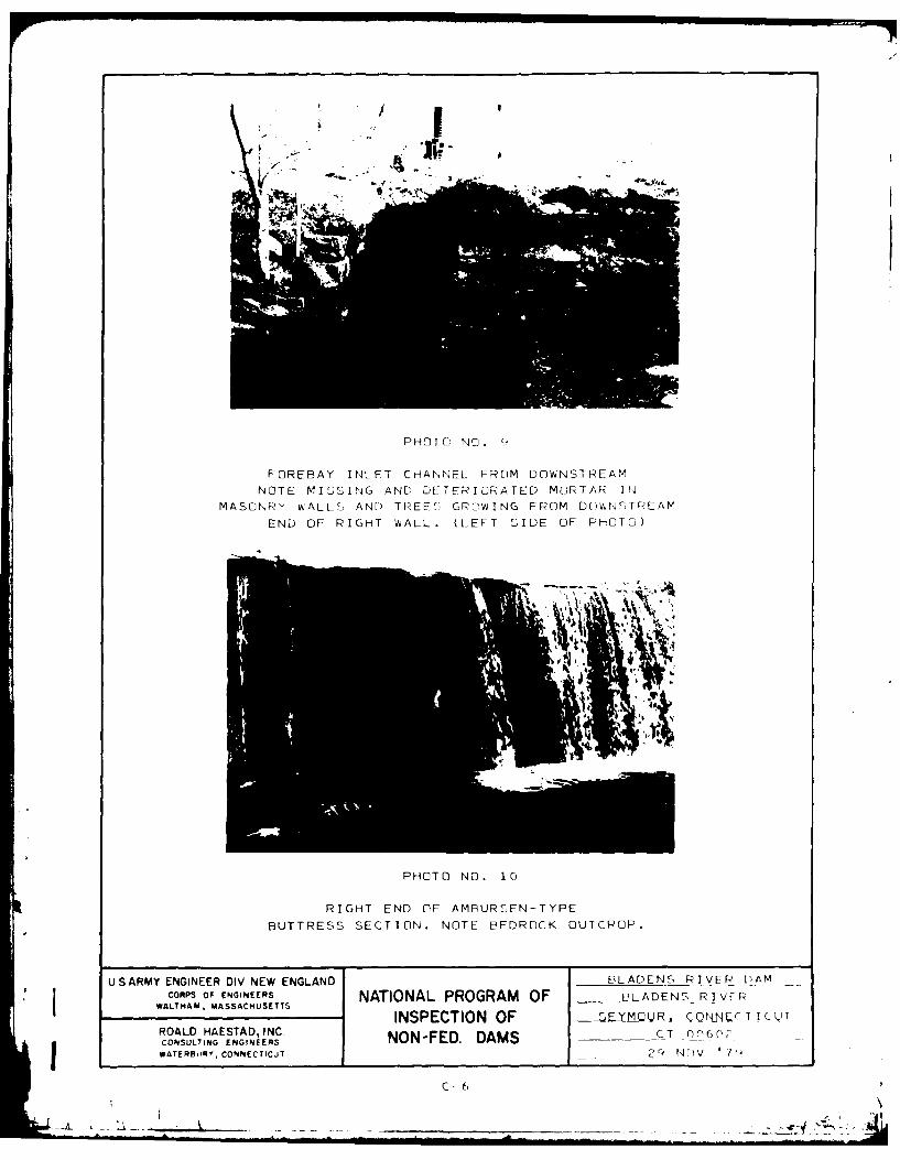
FOREBAY INLET CHANNEL FROM DOWNSTREAM
NOTE MISSING AND DETERIODRATED MORTAR IN
MASONRY W'ALLC, AND) TREE', GROWING FROM DUVWNS'TREAVM
END OF RIGHT WALL. (LEFT 'SIDE OF PHOTO)
PHOTO NO. 10
RIGHT END OF AMPURSEN-TYPE
BUTTRESS SECTION. NOTE BEDROCK OUTCROP.
US ARMY ENGINEER DIV NEW ENLAD3LADENS RIVER DAMCORPS OF ENGINEERS NATIONAL PROGRAM OF PLADENS RIVER
WALTHAM, MASSACHU SETTS INSPECTION OF 7, Y-UR,. CQ"L4C II C QROALD HAESTAD, INC. N -F.DASCT 0(-6(l,
gCONSULTING ENGINEERSNO -E .D M
WATERIFIOR, CONNECTICUT 2(4 NOlV 7'
C- 6

APPENDIX D
HYDROLOGIC AND HYDRAULIC COMPUTATIONS
*1i
I A;
-~~ ~ >%5N
4w-.*
Lo
~ Jr -
L4.
-. N -. " N U-
m . - 7

N.N
I.

-~> ~ --- ~A'-~ FIGURE 4
--4 )
C'
- -- .c
V 7 , .~ ? '-~ '- X
~~/. C~ / 4-S.
..........
71 a
WIN r'- >AETAD IN RYEGNERDVNWEG
5-l r-l~w .4O' Cy.5.Aff
C5.4.CU * MS
'--4LPOGA FiSEC1NO ON-E"OM
::1-7'S--
I,~4*-4
'Ell
BY ........ .DATE..-/A.T. ROALD HAESTAD, INC. SHEET NO ..... 1 ..... OF./CONSULTING ENGINEERS
CKD BY , DATE 37 Brookside Road - Waterbury, Conn. 06708 JOB NO ... 04 .- 1 0 ............
SUBJECT R..',A, ...... X./.J ... ... . ............ ,......'. ........ .. ,.....
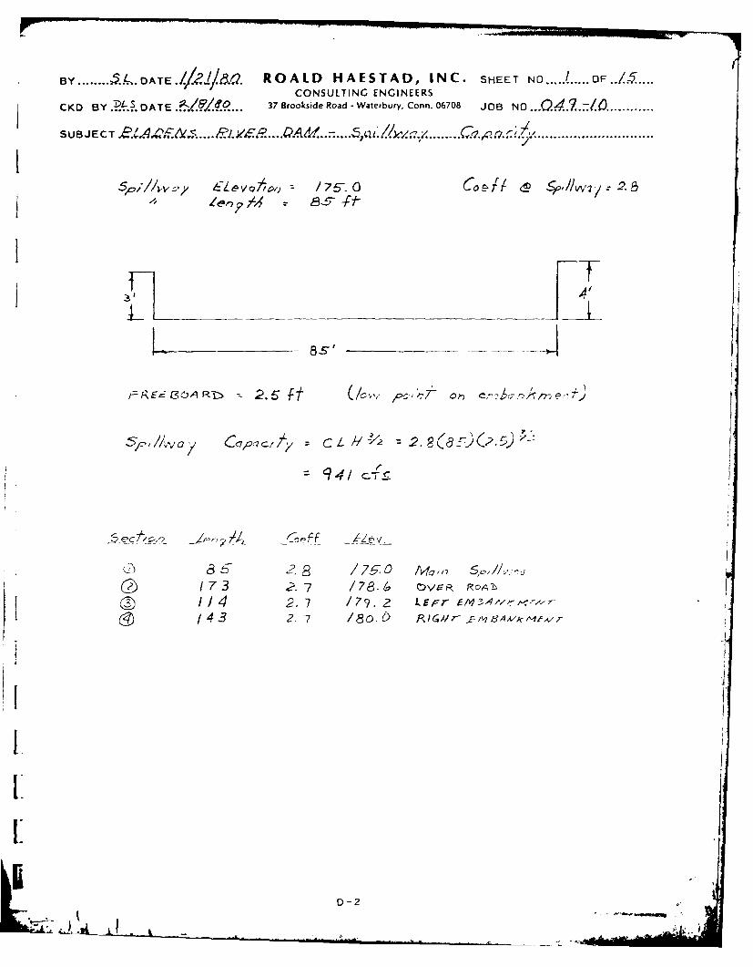
S~p, ,'v//wy 6 a-evo,,, : 75-. 0 fo / , /wt 2.3
-- 8-&'
?R~i O~ b :-2.5" ft" (/c', ,c.:.2:'-~ o e'?:- . ,~,:.
94,4
8 2.8 /7.0 M4 ,,7 ,//..
114 2. 7 /79. 2 LEFr iM'- -t-/ 43 2. 7 /80. & f, cG//r 16, 17 .. v,
I
D-2
- -,..

BY ......1...... DATE.//?..!. ROALD HAESTAD, INC. SHEET NO. ... . O...CONSULTING ENGINEERS
CKD BY .. D.. DATE .. /?./ ... 37 Brookside Road - Waterbury, Conn. 06706 JOB NO ..Q....J... .............
SUBJECT.&A4 t. .... ..Vg. ...P4 M..-.....A1 ./ ../ 7 ! .... '.q. 1. a .. ....................... ........
SeOLT 77LZ
/7,5 o 0 0
/76 238 0 o 0 238
/77 .673 0 0 0 6 7
3 /,237 0 0-o 7
/7. 2 04? 2/7 0 _,2.96
/807 2, 774 220 0 3,655
/8/ 3478 ,7-37 743 3) 42e 4
/82 ,468 2, q2 ,,"4 /, 072 7, 8 7 0
/83 5385~ 4, 3/i ~ 2 8 2 oc /c ,a
/84 642 / 32-7 3 087 /8613
D-3
- w IIIMM

BY ... ROALD HAESTAD, INC. SHETE T NO...: ...... OF./.CONSULNG ENGINEERS
I
CKD BY PA!?> DATE 17 Brookside Road - Waterburv, Conn. 06708 JB N .... /O . .SUBJCT./V~..A'$~ 7JOB4 NCLL -.........
S UB EC 4pQ, *1k q. ... C7,-"7 .... C U V J ..............
. . . .. . . . . .4
(JJ
10~
A V /~J A 7 7/d 5- 3'Ac Y OJ 111 131
D-4

BY. ROALD KAESTAD, INC. SHEET NO.... OF../ CONSULTING ENGINEERS
CKD BY EA?4A DATE 37 Brosd Road - Waterburyv, Conn. 06708 JOB NO ............J
SUBJECT .......Y~ .. 42 .....................
~D~-,7 . 4req z 464 acres /(0.1 / 9 sq~.
7~r-cqrr)
k=6.6 Arc 7 rr, -Sf /1w-- c 7-' fu r-V
67CP, /7.4 o~re-- [7 5,7c Str,;;
0. 0 3 f rcr)ff
! 'y
4941
S- 9D-5
T.. Z' .. ,,..k' . ,.. ' ./ .... 3 ' ' 5 .. .z,/.. . J. .. /.........................
7A_,/ .'-/ U-- 0-5,

BY ........ .-5.. DATE.../L/.. ... ROALD HAESTAD, INC. SHEET NO ...... .. OF...CONSULTING ENGINEERS
CKD BY k.&. . DA TrE ./ /....... 37 Brookside Road -Waterbury, Conn. 06708 JOB NO .. 2~ .5£.:..1Q............
S U B J E C T ....... ...................
SRervo/'r r o r e 3 '77e oF c 7,/hvre- o r'a Ie al §,,,IIay Level +
Fre eAQirz1 -Sto r-e
= - ,,-c./-c 1rel x (4vemye cl"-/' -re c.-wc9 )
$ Qc- r(/~ 3f1#)se A lc~
WL ~ 40y,.u er C-, jt qe~' qcro S~ee j-,F,-,A, he,'// 6.4(220) 0 3.8f-
Yo 7 I-rc A,- 1 7/ rrcm riVer 7e'- o -:r r, _-7
/3~ 20S
9 ,-- (68) 3q2.2 (2oy'2- /3,23. /3 . s-c
t, /16.2 fl A,4. 57 ft
-I,-Op, (TRI-.AL , .) it Opj (v- V16 1 2- 3 . - -FC 3/o', '7 fs
A~ 4x L e,79 A (42 40 fsd P 9 us e 4 ac-CiI .2 2
1/ 4. 2 4Ct
D-6

BY ..... ... DATE.-/.1-DITE a... ROALD HAESTAD, INC. SHEET NO ....... ... OF.CONSULTING ENGINEERS
CKD BY ..-A. DATE ..." /"..... 37 Brookside Road- Waterbury, Conn. 06708 JOB NO ..............
SUBJECT . AA .iN. .... P LVA R .... 4..7.A 9 w .... ..... Ro.q.t2;2 ..............................
5ECT1ON, NO 2 ReacJ Le,?*b 4-00 17
QP29 -5,3 cFs
h a' /2.8 Ft Az- 860 £eq
'4. k A- L en~' 9 (860 'x 400 P)x X4 40 o 7'8~ 9 & 8c-#
V', /.s ege.,a/ to X? of t . reacl ? O. .
Qp 3 (T,'AL) =Gp, (/-vS ) 9,513 cA.(- YC) 4,757 C-)S
H3 I2 h- As: 5-o s7 -ft
V- V A ALe..iM•(5"0fi/eA4Cof/P Jo 5gO/" 3 5 Qse 5 6c- T1
2 2
5ECT/O/V /VO 3 Rea,-/ Ze,q 7 % o 7
~ 564 8 cls
A 3 x ~~4
V73 7/9 Use 7 qc-ft
V3 A's /e-s-s 11"2'? Vz C4 . I-eocb 0-K./1
Gp 4 (T tR/A l - ) p3 (I- V'/.S)= 648 c6 (/ 6 - 3/ 77 C1ES
H 6 9. 7 A4 A o f-t
V 44xLe -9 1A (30 x540 1S-6 0' k r 3.98 QS L 4 o C-[-
2 1
D-7-~ , __ _

BY ....... DATE.- ROALD HAESTAD, INC. SHEET NO ........ .OF....
CONSULTING ENGINEERS
CKD BY .P DATE ./C) 37 Brookside Road - Waterbury, Conn. 06708 JOB NO .Q....-O
SU .JECT. DAT ... . F'.. 1...............................
SECT/O/V O Read Len?"/ = 56e feet
Qp 4 3, 707 cf
14 =/0. 3 ft A4: 330 s. ft
V z, 4 4KL e,1,7 A7 (330 'A 50 /J,)X :%If 56O0P' = 4.24 qcse 4 -
'V4 Is /ess 1a). ya Of 6 /e1-5 ,~ 0111
G P5 (rq 1AL) =0p4Ci %~~ =3, 7 07 4114 ~A 2, 7B 136
I5 -7.7 ft As: /90 s
V5 AS A Lency/i (Iqo ;ff,, 5"40 f,)A loc- 5 ' " 2.44 use 2_,c- 4
-w_ = V6 V4-_ 2 *4 - 3 7c-it2 2
i~ ~ O- =p Ge O IVov"./. : 70 7 Y16l" )- eO2' '
5ECTION & (Al Gp,//lA/d/)
0 pm 3,012 cfs
h1_5 3A? f Vs- /0 PC-
Hp- (79 1 L: ps - V>:l z5a- 3 0c
Vove if±1_ - 5_ e 7.5 ,c-f
Qp 5 VI- '5) 3012 r4S 'Y16 1 ) OO C-r-5
2.7t
7,'" ' " "' ['" - .D,-. . . .. ,..,8.~ .i, ,=: .. Z Jl" l
BY .......... 5..DATE. ,/.'Q-... ROALD HAESTAD, INC. SHEET NO ........ 5.OF.CONSULTING ENGINEERS
CKD BY ... DATE 37 Brookside Road - Waterbury, Conn. 06708 O .C KD B Y .P U D A TE ... Z ...A i: ... JO B N O ... Q . .-. 1 0... ...............
SUB JECT....l /. .... '. v.R 4.... A ...................................
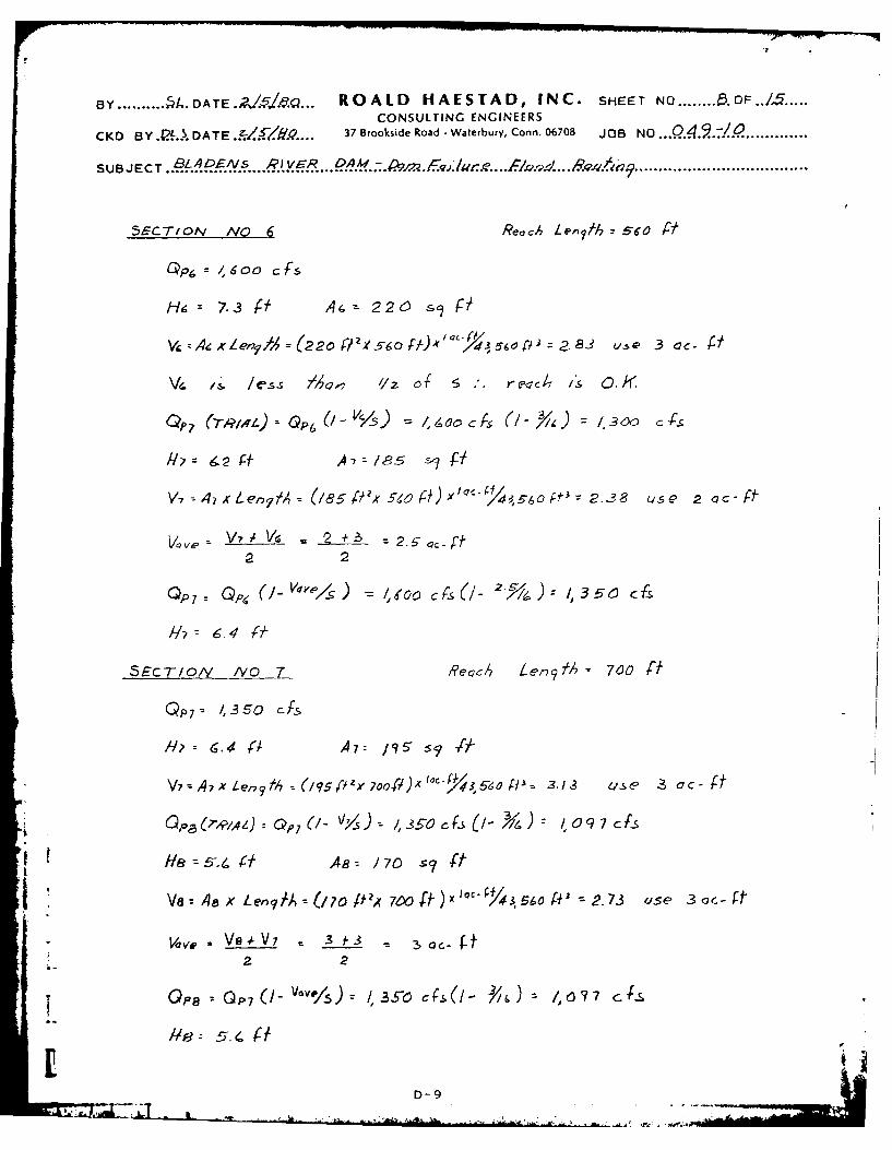
5ECT/ON NO 6 Reach Len?/% 5- 5o Al
He. 7-3 A- 226 sg/
, x ZeV1,4 x (2 20 P'x e 560 f, )' '1,Y114 ,6o r = 83 -S &,., 3 c
Ve s. /ess 74 '/z o e c. IS 0.1 .
OP. (-r9/A'z) = 0P (- V/ 5 ) - 4Y/e 3f~(- ~ ,0 cf-,S
P7= 62 Cf A'z/'R5 '-7T
V-1i 4 x Len~lA (185 P'x 569, 0) Y""Yjk, 5 _6o 2.38 qise 2 cc- f
V~e V7' Vd 2±At ~2 f2 2
QP7 3 ,.de 4 ~ j/ 5,j) /36
//r = 4 f-
SECTION A'O 7 ,qeoc,4 Ler-79 h 700 ft
QP 7 . 1,350 c fs
W 6 .4 10 A 7 9 -~ 1,4-
V,A, LXen f17 (/ 9 5 0 ex 700)xc0" . 3.13 Us,- 3 OC- ft
GPa OP7 -, 3-50 YS / 0 9 7 cS
V 4ax Lenl A (17ol Wx 70o t cxI -6 //3 o " 2.73 ese 3 ac- f-f
Va V'p VO -k 3 73 3
OGoa 0P7('- V"1)5 /3 'so (- 7 7C
/6: . . ft
D-9IL IL _A--

BY ...... 4... DATE.i?/ 4/s.0 ROALD HAESTAD, INC. SHEET NO..9. O
CONSULTING ENGINEERS
C KD B Y D DATE ... 37 8moklide Road - Waterbury, Conn. 06708 JOB NO-. 9n/ .......
-SEcTr/oN 1No // S c~;I~O An~riz.- (E~F6L-RE ) ....... .. z 20 Vert.
- qcoj L=400 fl
* .4 3.3 10 .3 0035 //7
8 41 200 4.89 003-5. 16.1 22012 4 9I 300 6.12 .0-2-5 /8.7 56 /0/7 74 620 '9-38 0.035 23.0 14,26 0
o24 6 . . . /01 4
/8- DI5ChARCQA . .oo .C..A
0 /2
6
4Q . . . . .S . 7
D-10

B Y. D4 A T E./ .. ROALD HAESTAD, INC. SHEET NO.../..Q... OFK.CONSULTING ENGINEERS
CKD By DATE 17 Brook%ide Road - Waierbury, Conn. 06708 JO NO.Q4.:1Q
.UB..C..A...9/... JOB. N.......9..7Q..........
SU3JCTICW 4 A0,/V 9A1,cR . v tf7..Soe./~~'/o
.. . . ................................
4 .33 /00. 3c 03 ~ 0.8 8803 4 I 200 4.89 0-02 12.1 2?420
198 .535 2.70 a02LO 2 4,387/4285. 1,272 4.46 0.0o. /1.4 14,,509
0
-4
0 4 0 21
-7

BY .... DL DATE .. ROALD HAESTAD, INC. SHEET NOD//...OF.../5 ...CONSULTING ENGINEERS
CKD BY ..P. . D A TE .A/C/.......317 Brookside Road -Waterbury, Conn. 06708 JOB NO..49..q ........
SUBJECT.BLADR'E S RI VER ... M .........................................................
SEcT/NN ~/ "~'/o~
L"2'Vert
L. . . . . . . . . . . . .
L. 0. 06V
4 -3 100 a.03 00(a 8.4 840S4.1 . oo . 4-39 atoi 8 S. 2300
12 133 512 3.85 0.w18 9.8 5,01814 . /71 766 4.48 a-0/8 /0.9 8.2345
/2
4-0/
1 4
Q 2 . 5 7
AREA- IC00
0-12
7 -A.~

BY ..... DATE.~5J ROALD HAESTAD, INC. SHEET N ..12. F.. 5.CONSULTING ENGINEERS
CKD BY 4 .DATE .?4......37 Brook.sde Road - Waterbury, Conn. 06708 JOB NO . .4.2. 9 .......
SUBJECT.. ~..... F ? ... )9................................................................
433 . 100 3.03 02 06'
841 40 e025 /0,6 2,900
/0. 10/O 310 307 0.029 /0.7 o12 017 494 .422 0.029 /3.3 ~570
/0
I0
46
D15 AI P4.- -lo s . .
1u 2
2 3
00 L
2 3
j . . . .ARE~A /00 -c
D-i

SY......... OATE./~~. ROALD HAESIAD, INC. SHEET N.. .CONSULTING ENGINEERS
CKO By .?.OATE.:I?.. 17 Brookside Road - Warury, Conn. 06708 JOB NO-9...9:i........
S UB JE CT ..94A4Q'? P M. IF9.Q.... Ra..'. 7 . ........ . . . . . . . . . . . . . . . . . . . . . . . . . . . . . . . . . . . . . . .
. . . . . . RO5 Q
5c4AI;'- " 30' #lartz
100' *
C~f @ P/ IW . 3.7-.5,Wrfa re .4req Z 41 gcf-es .(As.s~, ,rec Co sq7nf)
7, "00 ve', S//i)vqy Pcad< Totd7 Flowv 5toam~ Cap,,jc -ty
. 7. . 30 0 370 2.412.........-0 0 /,o047 4,823 - 1,32 3 0 /,923 -7.23
4 .6 --0- 1.35. 3, 09 5 10.2 1
4
£DI5CHARlqoc - 100o-
.44
5STOFA. CAP, :: -y -Acre - Feel'
0-14

BY ........ . DATE ROALD HAESTAD, INC. SHEET NO..../4..OF.....
CONSULTING ENGINEERS
CKD BY .P.:A. DATE .. /f/8 .... 17 Brookside Road - Waterbury, Conn. 06708 JOB NO .. .. / .............
SUBJECT ..... .9.YV .... ...... .l!2.37 ........................................................
SECTION AI 6 .. 1 . . e /L"= /.' .rz .
. . . . . . . . . . .. . . .
cn'e cuvert
. .wC. . / . . . . . .. . . ,-C I
4 033 2 0 30 6 0 0 /206. 050 38 30 I/140 i/80
8 -067 60 30 , 800 2.40
-6
' ,j ... .. . . . . . .i~~~~~ .. ... . .>-"i - i. . -''
k2
. . . . . i CHAROE -/ loo c7 . .
.* ....
V~ R'EA 0~~ 0
D-15, ' n- * Z. ,, . . " ._

BY ........ §A .8D A T. ROALD HAESTAD, INC. SHEET NO ..... OF./ 5
CONSULTING ENGINEERSC KD Y . D A TE .. j5~Q37 Brookside Road - Waterbury, Conn. 06708 JOB NO ..Q..:I ........
SUBJECT ........... . .jQ. 9 ~. .........................................
HwI r77i~7 fI~HJ Iiji/-rf
-0- - :L[
__ 38 301 1~/ 4!1 180-I - 6IEo L3 .0 11J8O-2 1'0 _
_ _ _ ~'I .
~LI 1 ~ ~~-K71 I
51 __ __ __ 2~o ~I254 ,
.I .( . .I
D0-16
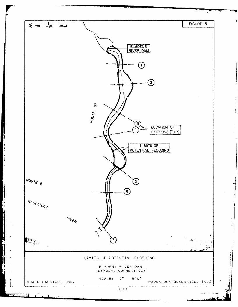
&I FIGURE 5
LRIERDAM]
LOCATION OFSECTIONS (TYP)
A / 4 A 7U ,,
IPITS CIF PLTINTIAL FI-ODING
PLADENS RIVER DAMSEYMOUR, CONNECTICUT
ROALO HAESTAD, INC. 'AL:I goNAUGATUCK QUADRANGLE 1972
D-17

APPENDIX E
INFORMATION AS CONTAINEID IN
THE NATIONAL INVFNT0RY OF DAMS

N. ~ALE~EA, ThIS T I