AD-AOG 365 AIR FORCE INST OF TECH WRIGHT-PATTERSON AFB OH SCHOOL--ETC F/G 21/5 AN ANALYSIS OF AIR FORCE MANAGEMENT OF TURBINE ENGINE MONITORIN--ETC(U) JUN 80 E B HUBBARO, 0 A SWECKER UNCLASSIFIED AFIT-LSSR 6-80 NL ;EEEEEEEllllhlll IIIIIIIIIIIIIIfllfllf ElllEEllEllllhE Elll//EEEEEl/IE EEEEEEEElllllEEI ElllllEllllEEEE
Transcript
AD-AOG 365 AIR FORCE INST OF TECH WRIGHT-PATTERSON AFB OH SCHOOL--ETC F/G 21/5AN ANALYSIS OF AIR FORCE MANAGEMENT OF TURBINE ENGINE MONITORIN--ETC(U)JUN 80 E B HUBBARO, 0 A SWECKER
Approved for public release;Disiribution Unlimited
DEPARTMENT OF THE AIR FORCE
AIR UNIVERSITY (ATC)
C AIR FORCE INSTITUTE OF TECHNOLOGY
LWright-Patterson Air Force Base, Ohio
80 9 22 057
All BBO RCE j GEMEM
Elbert B./Hubbard, 111' Captain, USAL'Gregory A Swecker( Captain, USAF
LSSR 688
Il
The contents of the document are technically accurate, andno sensitive items, detrimental ideas, or deleteriousinformation are contained therein. Furthermore, the viewsexpressed in the document are those of the author(s) and donot necessarily reflect the views of the School of Systemsand Logistics, the Air University, the Air Training Command,the United States Air Force, or the Department of Defense.
USAF SLCN 7S-20B AFIT Control Nuber LSSR 68-80
AFIT RESEARi ASSESS T
The purpose of this questionnaire is to determine the potential for currentand future applications of AFIT thesis research. Please return completedquestionnaires to: AFIT/ LSH (Tesis Feedback), Wright -Patterson AFB,Ohio 45433.
1. Did this research contribute to a current Air Force project?
a. Yes b. No
2. Do you believe this research topic is significant enough that it wouldhave been researched Cor contracted) by your organization or another agencyif AFIT had not researched it?
a. Yes b. No
3. The benefits of AT research can often be expressed by the equivalentvalue that your agency received by virtue of AFIT performing the research.Can you estimate what this research wuld have cost if it had beenaccomplished under contract or if it had been done in-house in terms of man-power and/or dollars?
a. Man-years _____$ ____ (Contract).
b. Man-years $ , (In-house).
4. Often it is not possible to attach equivalent dollar values to research,although the results of the research may, in fact, be important. Whether ornot you were able to establish an equivalent value for this research (3 above),what is your estimate of its significance?
a. Highly b. Significant c. Slightly d. Of NoSignificant Significant Significance
S. Coments:
,Um- and Grade Pos6ion
Organization L oatn
""till
BUSNES REPL MAILMAL
POSAIN WILL SI PAID IT AOlSSI _________
AIUILSH (Thesis feedback)Wright-Pact~rISOU An3 OU 4S433 ______
SECURITY CLASSIFICATION Of THIS PAGE (Mon Datt En__d),REPORT DOCUMEHTA.TION PAGE READ INSTRUCTIONS
BEFORE COMPLETING FORM
I. PORT NUMBll ''n 2. GOVT ACCESSION NO. I. RECIPIENT'S CATALOG NUMBER
LMS 68-80 AD /4A 3b____________4. TITLE (and Subtitle) S. TYPE OF REPORT & PERIOD COVERED
A. AALTSIS OP AIR BO1C MALAE OyT'URBIE mGEE NONI O3G SITM 8 (TEMS) Master's Thesis
S. PERFORMING OG. REPORT NUMBER
7. AUTHORfa) . S. CONTRACT OR GRANT NUMBER(s)
Elbert B. Abboaxd, -11 C&aPta USA.PGreory k. * Sweoker, Captaia, .TsU
S. PERFORMING ORGANIZATION NAME ANO ADORES I. PROGRAM ELEMENT. PROJECT. TASKS - 4 AREA WQNK UNIT NUMBNERS
Ai' .Pore Institute of Teoblnolog.T,WpU 0%I. CONTRQI.I.ING OFFICE NAME ANC AGORESS941• IL REPORT DATE
3) Dear~tmau- or Co=m1=icatlofl and June. 1980.w.1Ral1tes5 1S. NUMBER Of PAGES
ARITTI,- W&PB, OH 45433 10314, MONITORING AGENCY NAME A AbOOS S(ill dJifhouWn frm Cont,.ilinil Office) -IS. SECURITY CLASS. (of this Waort) 4
UNCLLBSUIMXS. OECL ASSI IrICATION/oOWN GRADING
SCH EDULE
1. DISTRIBUTION STATEMENT (of (his Repot)
Lpproyed for public releasel distribution Unlimited
17. DISTRIBUTION STATEMENT (of the abstract entered in Black 20, It difeent e ReLE)AR .A P O E D FO R P ~ I R E S E A FR Ig o 1 7
1. SUPPLEMENTARY MOTES
IS. KEY WOROS (Conlnue as teerse aid. Of noe.al'e, ond Identlfy by block number)
Tuzbine Engine Monitoring 87stemsR.gine Condition Monitoring On Condition Maintenance
SEngine Diasmostics* Engine Manuagement
* 20. ABSTRACT (Contie a. rev*er* aide it n.ce.-r d detity y, Nock fhm-*b)
Thesis Chaix'mans Leslie J. Zaabo, MaJor, USUP
00o I 1473 EDITION Op I Nov 65 is OBSOLETE
SECURITY CLASSIFICATON OF THIS PAGE /USa. D.-. r1.r.d)
I-.
-I III I I I I- ., ,.
3Z-'hASSIFIEDSECURITY CLASSIFICATION OF THIS PAGE(When Oalc Encered)
Turbine Engine Monitoring Systems (TEMS) are engine health moni-toring and diagnostic tools being developed and tested for use onAir Force engines in order to improve and reduce the cost ofengine maintenance and management and to aid in the implementationof On Condition Maintenance. Previous researchers have describedthe major features of TEMS, analyzed the results of developmentand test efforts, and identified problems which must be overcome.This study examines the problem of fragmentation which exists in
the Air Force management of TEMS development and testing. Theauthors describe and analyze the overall Air Force management ofTEMS. Management problems were identified and classified intothree major areas: structure and role problems, information flowand integration problems, and leadership and command problems.Four alternative management concepts were analyzed. Based on thisanalysis, the authors recommend that the management structure bemodified, and a TEMS Task Force be established to more effectivelyutilize TEMS for Air Force engine maintenance and management.
UhiCI"ASIFilmSECIIITY CLASSIFICATION OF 1", PAGFrlwehn Date .ntli
LSSR 68-80
AN ANALYSIS OF AIR FORCE MANAGEMENT OF TURBINE
ENGINE MONITORING SYSTEMS (TEMS)
A Thesis
Presented to the Faculty of the School of Systems and Logistics
of the Air Force Institute of Technology
Air University
In Partial Fulfillment of the Requirements for the
Degree of Master of Science in Logistics Management
BY
Elbert B. Hubbard, III, BS Gregory A. Swecker, BSCaptain, USAF Captain, USAF
June 1980
Approved for public release;distribution unlimited
/t
This thesis, written by
Captain Elbert B. Hubbard, III
and
Captain Gregory A. Swecker
has been accepted by the undersigned on behalf of the fac-ulty of the School of Systems and Logistics in partial ful-fillment of the requirements for the degree of
MASTER OF SCIENCE IN LOGISTICS MANAGMNT
DATE: 9 June 1980
SCOMMITtEB/ CHAIRMAN
ii
ACKNOWLEDGMENTS
The authors wish to express their sincere appre-
ciation to those people whose assistance was vital to the
completion of this study. Special "thanks" go out to those
who gave of their time, knowledge, and expertise in allow-
ing themselves to be interviewed. Without their candid
insights, this study could not have been completed. The
guidance and patience of our thesis chairman, Major Leslie
Zambo, whose continual help was needed to overcome missed
deadlines, was crucial to the accomplishment of this study.
The interpretation of hand-written drafts and the typing
speed and skill of our typist, Mrs. Marianne Ramsey, were
especially appreciated.
The contribution of these individuals provided
the support without which this work would have been
impossible. However, the content and validity of this
study are solely the responsibility of the authors.
and budgeting, reduced spare engine and parts requirements,
reduced base maintenance requirements, reduced depot main-
tenance requirements, and reduced transportation costs
(4:1).
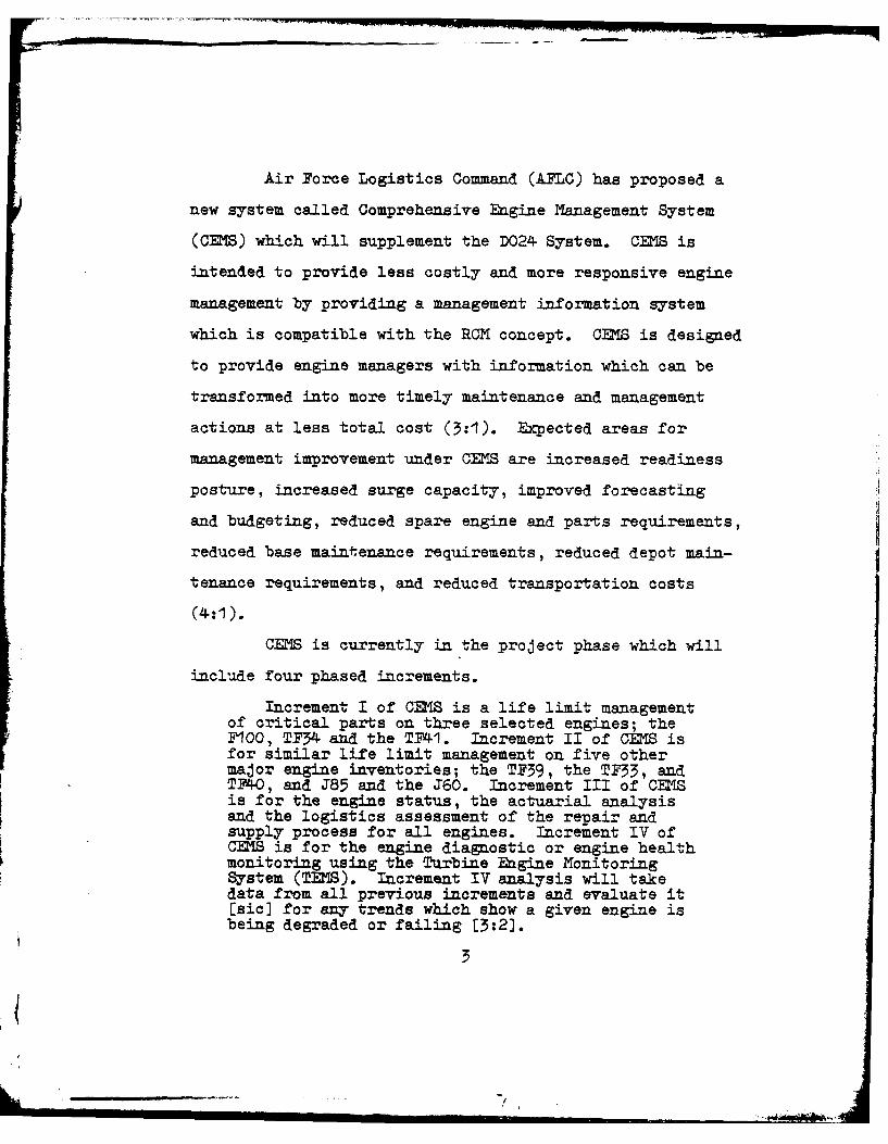
CEMS is currently in the project phase which will
include four phased increments.
Increment I of CEMS is a life limit managementof critical parts on three selected engines; the7100, TF34 and the TF41. Increment II of CEMS isfor similar life limit management on five othermajor engine inventories; the TF39, the TF33, andTF40, and J85 and the J60. Increment III of CEMSis for the engine status, the actuarial analysisand the logistics assessment of the repair andsupply process for all engines. Increment IV ofCEMS is for the engine diagnostic or engine healthmonitoring using the Turbine Engine MonitoringSystem (TEMS). Increment IV analysis will takedata from all previous increments and evaluate it[sic] for any trends which show a given engine isbeing degraded or failing [3:2].
3
JI
Turbine Engine Monitoring Systems (TEMS) will
become an integral part of CRS in Increment IV.
Currently, a profusion of TEMS using a variety cf tech-
niques and approaches to gathering data are in various
stages of development, test, and operation. An extensive
study by Degrande and Eickmann concluded that TENS is
feasible and necessary to meet future Air Force needs.
Their paper concluded that TEMS utilization could:
TEMS related maintenance costs, increased TEMS acquisition
costs, increased personnel training costs, and increased
complexity of the interfaces with the engine information
management system. These potential problem areas may
decrease the responsiveness and increase the cost of the
Air Force engine management system.
OBJECTIVE
The objective of this thesis is to develop a
practicable management concept capable of effectively
dealing with present and future problems associated with
U.S. Air Force Turbine Engine Monitoring Systems (TEMS).
5
RESEARCH BYPOTBESES
1. The present management structure for TENS
development and implementation is inadequate to meet the
needs of the Air Force.
2. A single manager concept for TENS would be the
most beneficial approach to the overall management of Air
Force engine monitoring systems.
MESEARCH QUESTIONS
1. Which Air Force agencies are directly involvedin the planning, development, or implementation of TENS?
2. What is the extent and relationship of eachagency's involvement in the engine monitoring systems?
3. What are the advantages and disadvantages ofthe present TENS management structure?
4. What would be the advantages and disadvantagesof a TIES single-manager structure?
RESEARCH DESIGN
This research effort was exploratory and
descriptive in nature, and was looking for useful insights
and ideas rather than statistically oriented information.
The primary means of obtaining information were the review
of pertinent literature and personal interviews with
people who had practical experience with TENS. An attempt
6
...............
was made to gather and synthesize information and
9experience by gaining insight into relevant interfaces andrelationships between various agencies involved with TEMS.
Sources of Information
1. Literature Review. A thorough search for
literature relevant to TEKS provided numerous articles,
studies, reports, and theses from which to draw n.ufor-
mation. In addition, briefing guides, technical reports,
plans, films, policy letters, and other written documen-
tation were provided by Air Force Logistics Command (AFLC)
and Aeronautical Systems Division (ASD). Although a large
amount of written information concerning TENS was available,
very little information about the management structure of
the TEMS program was found.
2. Personal Interviews. Due to the limited
amount of literature concerning the TENS management
structure, heavy reliance was placed on information
obtained from personal interviews. Members of several
Air Force agencies involved in engine management and TENS
were contacted. These people held positions from which
various aspects of the TENS program could be observed,
and they had acquired a pool of experience and infor-
mation from which to draw. Many of these personnel were
located at Wright-Patterson AFB, Ohio, assigned to HQ
7
l/
AFLC and Aeronautical Systems Division (ASD). Subordinate
organizations of concern include AFLC Directorate of
Propulsion Systems (LOP), AFLC Logistics Operations
Comprehensive Engine Management System (LO CEMS), ASD
Directorate of Engineering and Test (ZE), ASD New Engine
Program Office (Y23), the Aero Propulsion Laboratory (APL),
and Air Force Acquisition Logistics Division (AFALD)
Directorate of Propulsion Logistics (YZL).
Respondents were chosen from these particular
organizations because each organization has a role in
planning, development, or implementation of TEMS programs.
Organizations which were not intimately affiliated with
some aspect of TEMS were not included as sources for this
research effort.
During all personal interviews, variations in
points of view were highly encouraged and sought after.
Due to the heterogeneous nature of the organizations
considered and different types of experiences of indi-
vidual respondents within these organizations, it was
expected that different points of view and insights would
be gained.
Scove
The research was divided into four parts. The
first part included a thorough literature review and
8
unstructured interviews with individuals who by reason of
their previous experience and present positions had become
specialists in various areas related to TENS. This infor-
mation was collected, consolidated, and used to gain a
general understanding of Air Force engine management and
maintenance procedures, capabilities of various past and
present ThS equipment, and past and present uses of TMS
equipment. The initial interviews were not intended to be
highly systematic, but rather were designed to be a
flexible first step to form a basis for parts two, three,
and four.
Part two involved a clarification of the issues
concerning TENS which had become apparent after analyzing
the information gained during part one. From this
analysis a structured interview guide (Appendix) was
designed to ensure that all persons interviewed responded
to the same set of specific questions. This systematic
interview guide was also designed to remain somewhat
flexible to allow respondents the freedom to raise issues
and questions not previously considered. All previous
respondents were interviewed a second time using the
structured interview guide.
Part three included an analysis of information
gathered in part two. This led to the development of a
conceptual representation of the TES organizational
9
interrelationships perceived ty the respondents. Also,
several alternative concepts were formulated to attempt to
overcome the management problems identified by the
respondents.
In part four, the alternative organizational
concepts were presented to the personnel previously inter-
viewed. The interviewees were questioned as to the
advantages and disadvantages of each alternative. Advan-
tages and disadvantages of each concept were identified
and analyzed. From this analysis, a.lodified organiza-
tional concept was developed to provide a recommended
structure for effectively utilizing TENS for Air Force
engine management.
10
AM~r
Chapter 2
LITERATURE REVIEW
AIR FORCE ENGINE MANAGEMENT SYSTEM
The Air Force engine management system consists
of three management levels (command level, depot level,
and base level) (12:11). The command management level
includes HQ USAF and HQ AFLC. HQ USAF is ultimately
responsible for the overall performance of the engine
management system for the entire USAF engine inventory
(8:12-13). The primary functions include engine
management policy and guidance, determination of future
management requirements, and surveillance of the engine
reporting system. In general, these responsibilities
have been directly delegated to HQ AFLC. In this capa-
city HQ AFLC attempts to integrate engine logistics
support for all Air Force organizations involved in
engine management. This is accomplished over the entire
life cycle of all engines. In order to facilitate
integration of engine logistic support Air Force wide,
AMC has established policies for inventory control and
maintenance procedures, and has also developed the soft-
ware to perform logistical analysis and support (12:14).
L1
The second engine management level, depot level,
consists of two Air Logistics Centers (ALCs): Oklahoma
City AC and San Antonio ALC. At each of these ALCs there
are Engine Item Managers (EIMs) who are assigned overall
responsibility for managing particular engine types.
EIMs process and use historical data to fore-cast failures and scheduled removals over a twoyear period, to predict workloads, spare partsprocurement, and to calculate stockage objectivesfor both depot and base levels F12:13-141.
The third management level, base level, is the
lowest management level within the system. Management is
performed by the Base Engine Manager (EM) who monitors the
inventory and movement of all the engines which are assigned
to the base. One of the EM's primary tasks is to ensure
that engine status change reports are submitted in an
accurate and timely manner.
In addition to the engine management levels, the
operational commands provide a parallel management
function. The Major Command Engine Managers (MAJCOM EMs)
are concermed with monitoring fleet performance. They
require a high degree of visibility into engine health
for determination of the mission performance capability
and readiness posture of each base and the overall command
fleet.
12
J . . . . . = :,- j . _ , .. ,. - . .
Like their counterparts at the ALC's, MAJCOMEMs also predict workloads, determine spare enginerequirements, and calculate stockage objectives[8:14-151.
AIR FORCE ENGINE MAINTENANCE SYSTEM
The engine maintenance system also consists of
three levels: flight line level, Jet Engine Intermediate
Maintenance (JEIM), and depot level.
Figure I illustrates the various interrelationships
between these levels by depicting the engine maintenance
flow cycle. The lowest engine maintenance level is flight
line maintenance which is designed to troubleshoot engine
problems on the flight line while the engine is still
installed on the aircraft. Flight line maintenance has
liited repair capability but can repair many minor engine
discrepancies. If a repair capability exists at this
level, the engine is repaired (subject to monetary and
manhour constraints) while still installed on the aircraft
and is returned to operation. Problems which are not
repairable at the flight line level are assigned to JEIM.
The transition from flight line maintenanceto JEIM is predicated upon the identification ofscheduled or unscheduled tasks which requireengine removal. Factors which indicate removalof the engine have included estimated repair time,capability to repair the failure while the engineis installed and ability to accurately identifythe failure [12:111.
13
0
0
0 0
o
E-4 L
0 1 0
-I
0~ 0 I 0
LO :Z 4-
r4 Q)
1 0 0101
+;4 0404,
4 -0 - , *)r-4 H4H ~,Pqr-f 4~4
I .OO,04-1 4.1)0 ' P414*U 0-1 o 4f94po
r- 4- H9$ -H 04.)0r4 0
I Id 01) 04- 404U4I a) i', P40 P4%9j (I 4.) 0 4 ) 0 I M P 4 V4 ' 4 -) M
I r- 4- 0 4) 4-J 102
1 4JP4 ) Ci 4
14)4L 4 I d D(L, 0 '
I4 Q)o9 4
boM-i d4 . ordr
Jet Engine Intermediate Maintenance may be conducted
at the base or at a centralized engine repair facility.
JEIM troubleshoots the engine to assess the problem and
evaluates whether the capability is available to repair or
modify the engine. If JEIM possesses repair capability,
the work is accomplished (subject to monetary and manhour
constraints), and the engine is retuned to the flight
line for reinstallation on an aircraft or for placement in
the base spare engine inventory. If repair is beyond the
capability of JEIM, the engine is sent to the depot level.
A spare engine may be made available to the flight line
from the base spare inventory, if needed.
The transition from J= to depot levelmaintenance has been determined by several factorsincluding criticality of the base engine stocklevel, cost of repair versus hours remaining beforemaximum operating time, possibility of discrepanciesundetectable at base level, and failure of baselevel maintenance to correct discrepancies [12:13].
After receiving an engine needing repair, modifi-
cation or overhaul, the depot will determine whether or
not it is practical to repair. If not, engine components
are either salvaged or disposed of.
Engines which are repaired are then shipped back
to the base level to be installed on an aircraft or to
be placed in the base engine spare inventory. The depot
also has an engine spare inventory which can be used to
provide spare engines to the base level when needed.
15
DO24, PROPULSION UNIT LOGISTICS SYSTEM
The management information system used by the Air
Force to manage its entire engine inventory is known as
the D024, Propulsion Unit Logistics System. This system
uses a base line file which facilitates selective
management through serialized control of the Air Force
engine inventory (8:15). Oklahoma City ALC serves as the
central point of contact for information relating to all
reportable aspects of an Air Force engine (primarily
because Oklahoma City is the location of the system's
central computer).
The primary objectives of the D024 System include
specifying how to manage engines and monitoring how well
engines are being managed.
Data collected are intended to providemanagement with the information needed to determineallocation of funds, procurement, computation ofoverhaul requirements, engine inventory anddistribution, spare engine requirements and disposal,and to provide the budget estimate. The inter-mediate objectives are to maintain an accurate andtimely engine inventory, to reduce pipeline times,to speed transportation, to reduce overhaul time,to extend field maintenance capabilities and, ingeneral, to streamline engine management techniques[8:12].
The source document for the D024, PropulsionUnit Logistics System, is the AF Form 1534, EngineStatus Report. This is a comprehensive formdesigned to follow a particular engine by serialnumber, from procurement through salvage [8:28].
16
This form is submitted by Base Engine Managers in order to
update the central engine master file (12:17). The AF Form
1534 includes such data as engine serial number, engine
location, engine condition, engine operating time, engine
removals, engine installations, engine shipped to or from
any location, and type of engine transaction (8:18; 12:20).
These data are input to the system central computer via
Automatic Digital Network (AUTODIN) for editing and
storage (8:18). The master data file is, therefore, able
to provide
a historical record of all transactionsthat have taken place on the engine, by serialnumber, from the time it was brought into the AirForce inventory until its subsequent removal(salvage through reclamation, transfer to anotherservice, or loss by crash) [8:141.
In order to provide specialized data system support
to the various engine management functions, the master file
data is analyzed and processed in several different formats
including D024B Item Inventory Control, D024C Allocation
Inventory Accounting, and D024K Actuarial Computation
Forecasts (8:28).
The NAJCOI Eis and AIC Efl's accomplish enginestatus monitoring through the use of D024 systemoutput products. Among these were daily status,condition and location information, weekly not-mission-capable (NMC) status for each serial
17
! I
numbered engine on a worldwide and command basis,monthly failure and inventory data, and quarterlyaverages of pipeline time. An update of operatinghours and inventory reconciliation was receivedquarterly from each AF engine reporting activity[12:21].
Users of D024 output data include HQ USAF, Major Air
Commands, Engine Item Managers, the National Guard Bureau,
the Air University, and HQ AFLC (8:17).
RIMIABILITY CENTRD MINT= A.CE (RCM)
The Federal Aviation Administration (FAA) recog-
nizes three primary maintenance processes (25:1). These
processes are included in the Air Force Reliability
Centered Maintenance Program (ROMP), which is defined as:
te .i.ea failure modes and effects analysistechnique (FMFA) for significant aircraft andengine structures, assemblies and items. It usesa decision logic procedure based on the Airlines/Manufacturers' Maintenance Planning Document,MSG-2. This structured approach to maintenancerequirements analysis, identifies minimum essentialrequirements consistent with safety and readiness[12:32].
The objective of the RCMP is to provide a main-
tenance plan that "... prevents deterioration of the
inherent design levels of reliability and operating
safety at the minimum practical cost [12:32]." To meet
this objective, aircraft components are analyzed and
placed into one of three maintenance categories. These
categories or processes are Hard Time Limit, On Condition,
and Condition Monitored (28:19).
18
Hard Time Limit
The Hard Time Limit category emphasizes the
prevention of failures. Maximum intervals are set for
performing maintenance based on the Maximum Operating Time
(MOT) of a component or end item. The MOT is established
from tests, operating experience, and safety factors and
is based on Mean Time Between Failures (MTBF). The MTBF
is measured in terms of flying hours which represent
usage. The var7ing usage associated with flying at
different altitudes, speeds, and other flight conditions
is not directly considered. Because engine usage is
dependent on variables other than flying hours, using
flight times on which to base the Hard Time Limit does
not accurately represent engine life remaining (25:2).
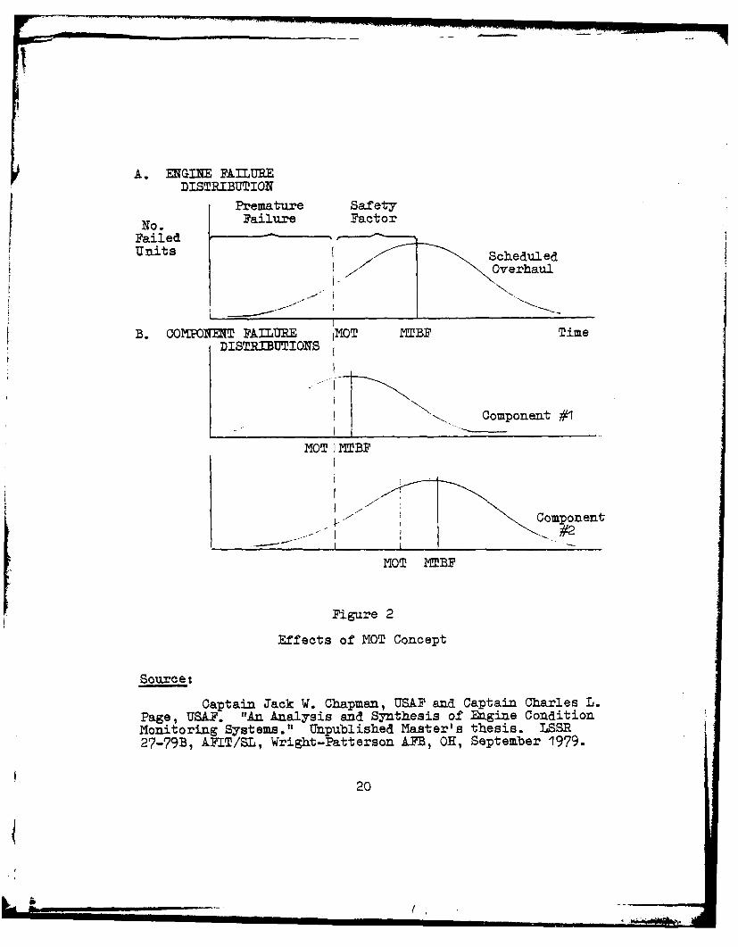
Chapman and Page developed the conceptualization
shown in Figure 2, which represents a bypothetical graph
of the effects of the MOT method on engine replacement.
Although this method usually results in repair before
failure, the efficiency of this method is suspect. In
Figure 2, Part A., the depiction of a theoretical normal
distribution of the number of engine failures over time
indicates that by establishing a MOT based on MTBP minus
a safety factor, a majority of engines would require
maintenance before the end of their useful life. Ertending
19
A. ENGINE FAILUREDISTRIBUTION
Premature Safety
No Failure FactorFail ed ""
Units ScheduledI Overhaul
B. COM ONENT FAILURE IMOT MTBF TimeDISTRIBUTIONS
Component #1
MOT NTBF
Component
- _ _ _ __ _ _
MOT MTBF
Figure 2
Effects of MOT Concept
Source:
Captain Jack W. Chapman, USAF and Captain Charles L.Page, USAF. "An Analysis and Synthesis of Engine ConditionMonitoring Systems." Unpublished Master's thesis. LSSR27-79B, AFIT/SL, Wright-Patterson AFB, OH, September 1979.
20
this conceptualization to engine components or modules,
Figure 2, Part B, depicts the engine MOT as being equal to
that of the engine component or module with the lowest MOT.
Significant amounts of operational readiness time could be
lost due to early scheduled maintenance for MOT components
(12:29-30).
The information necessary for base level engine
management of Hard Time Limit components is minimal. The
requirement exists only to track the operating times of
each of these components.
On Condition Maintenance (0C)
On Condition Maintenance seeks to prevent failures
by establishing periodic inspections or repetitive tests
to check component parts or end items against an opera-
tional standard. OCM is defined by AFR 66-14, Equipment
Maintenan.ce Policies. Oblectives. and Responsibilities, as:
The application of inspection and testingprocedures and techniques without removal or dis-assembly that allows the condition of equipment todictate the need for maintenance or the extent ofrepair required to restore serviceability [25:2].
The preceding definition identifies two key
advantages of the 0CM concept over the Hard Time Limit
Maintenance concept. One advantage is that inspection and
testing do not require removal or disassembly to determine
the condition of equipment. Byrd and Tall state that:
21
. For engines that are past their intro-ducto;r problems and the effects of dilutioncaused by new engine introduction into the fleet,maintenance costs are directly related to engineremoval rates [25:2].
The present overhaul concept of complete engine overhaul
at specified time limits is a critical cost burden to the
Air Force. OCM allows more maintenance tasks to be
performed at base level and reduces engine removal rates
(20; 33).
The second advantage of OCM is that the condition
of equipment is established as the basis for maintenance
and extent of repair rather than a Hard Time Limit. Under
the overhaul concept for MOTs, parts which show any
noticeable deterioration are replaced to ensure relia-
bility for another time interval. Many manhours and
resources are consumed repairing and replacing parts that
are not broken or excessively worn (25:2). In contrast,
under the OCM concept, these parts are repaired or
replaced based on their condition with respect to the
established standards for operational reliability. By
repairing or replacing only when necessary, manhours and
resources are conserved, and costs are reduced.
To effectively implement OCM, the requirement
exists to track the condition of individual components.
This factor requires additional information to be
available for the engine manager. One of the objectives
22
of TEMS development is to provide this information in a
manageable form.
Condition Monitored (CM)
This maintenance category includes items that have
neither Hard Time Limits nor any specific On Condition
inspection or monitoring system.
Condition monitoring is categorized as anunscheduled maintenance process [and] is primarilyapplicable to only those aircraft units the failureof which does not Jeopardize crew safety [28:28-29].
These items are repaired after failure is noted by the crew
or maintenance personnel.
Summary
The progression of Air Force engine maintenance
from maintenance management based completely on the
MOT concept to R' is expected to cut costs of engine
management. To more effectively implement RON and
increase the use of On Condition Maintenance, the CUS
and TES are being developed, tested, and implemented to
provide better and more timely information to engine
managers.
TUPRBINE ENGINE MONITORING SYSTEMS (TEMS)
The various TEMS programs have implemented
"manual/automatic data acquisition, sorting and storage
23
of data, and subsequent manual/computer processing and
trending" to put data "into a foLat which permits timely
and pertinent decisions to be made concerning maintenance,
logistics, operations, etc. C14 :3].." Most efforts have
centered on developing and testing diagnostic techniques
necessary to implement automatic engine monitoring. A
brief review of past and present engine monitoring programs
follows.
Early Systems
Engine Analyzer System (EASY) 1962-1967. This system was
tested cn 36 F-105 and F-4 aircraft to monitor performance
degradation. The large volume of data provided untimely
analysis and was difficult to interpret into maintenance
actions. The need for more reliable sensors, better data
correlation and sorting, and greater data compression was
indicated (14:DI).
Time Temperature Recorder Integrator (TTRI). This system
attempted to predict engine life based on engine temper-
atures recorded over a period of time and number of
operating cycles. A statistical relationship between
engine life and temperature measurements was not estab-
lished in the service tests (14:D-D2).
24
II
Turbine Engine Diagnostic System (TEDS) 1969-1971.
This program demonstrated the feasibility ofautomatically determining the mechanical conditionand functional status of turbine engines usingdata acquisition, interpretation, and processinghardware [14:D31.
Sensors correctly indicated problems in engines with bad
parts installed.
Operational Systems
Malfunction Analysis Detection and Recorder System (MADARS).
This system is installed on the C-5A and is the only
operational Ai Force automatic monitoring system. IADARS
monitors over 800 parameters on the airframe and its sub-
systems including 28 engine-related parameters. In-flight
monitoring is continuous, but data are recorded only when
commanded by the crew or when preselected parameter limits
are exceeded. Flags are displayed in the cockpit for out of
limit conditions which allow the flight engineer to
accomplish appropriate fault isolation procedures. The
data are ground processed and analyzed upon mission
completion at Oklahoma City ALC. In some instances feed-
back to maintenance personnel has been as low as 30
minutes. MkDARS data and trend information have been used
to increase time between overhaul (TBO) rates and to
detect abnormal deterioration rates. However,
25
{
- Zjn
According to AFC, only a small portion of theavailable MADARS data is presently used for enginemaintenance purposes. This situation exists dueto volume of data produced and to the absence ofengine maintenance concepts keyed to the use of theMADARS outputs [14:10].
In-flight Engine Condition Monitoring System (IECMS).
This system has recently been put into operational use by
the U.S. Navy on two squadrons of A-7E aircraft. The
major objective of this program is to detect in-flight
engine problems early enough to prevent aircraft loss.
Forty-nine engine and aircraft parameters are monitored
continuously and on-board analysis and recording takes
place (1) when parameters are exceeded, (2) during certain
flight operations, or (3) on pilot command. This system
provides an on-board malfunction indication system which
wams the crew of damage which may threaten mission
completion. Flags are set in the maintenance avionics
bay for less severe malfunctions, and basic maintenance
requirements are identified to indicate turn-around
readiness status. Ground analysis processes the data for
fault isolation and trending and provides printouts for
corrective actions to be performed by maintenance personnel
(30:19).
Strategic Air Command (SAC) Reliability Improvement Pro-
gram (RIP) (5; 6). SAC RIP is a program designed to
26
4
improve engine reliability for all KC and EC-135s and B-52
aircraft within SAC. The specific objectives of SAC RIP
are: (1) To predict engine failures before they occur.
(This is predicated on early detection of engine problems);
(2) To reduce air aborts and in-flight shutdowns; and
(3) To improve engine management in order to reduce main-
tenance costs. The means used to accomplish these objec-
tives include: (1) Partial power takeoffs which lower the
severity of engine use; (2) Normal engine care; and
maintenance. If visual inspection confirms a problem,
then appropriate maintenance is accomplished. After
corrective maintenance is performed, the engine is checked
28
for signature improvement. If the signature reveals a
change back to the original characteristics, then it
indicates that the problem was corrected. If, however,
the signature remains abnormal, the source of this
deviation has not been determined. Continued observation
and interpretation is necessary.
The key to the ECNP is accurate and timely
recording of in-flight observations by flight crews.
Developmental/Test Systems
F-I00 Engine Diagnostic System (EDS). EDS is designed for
use with the F-100 engine, the propulsion system for the
F-15 and F-16 aircraft. The F-IC0 FDS program is currently
in engineering development with a ten month demonstration
program to follow (7:5). EDS is configured to fault
isolate various Line Replacement Units (LRUs) on the flight
line, and major gas path components at the intermediate
level (23:4-12).
EDS consists of approximately 40 engine mounted
sensors for measuring 44 engine performance parameters.
EDS hardware includes an engine mounted multiplex unit
(EUX) for signal conditioning and analog to digital
conversion, an airframe mounted Data Processing Unit (DPU)
to monitor and record selected signals, and a ground
suitcase type Diagnostic Display Unit (DDU) for data
29
transfer fault isolation, and to aid in performing ground
engine trim (23:3-1). The system continuously monitors
engine operating conditions and records data when: (1)
normal operating limits are exceeded, (2) the aircraft
flies through trend and performance check "windows", and
(3) on pilot command (23:4-1). Any detected event which
is out of limits initiates data recording for the five
seconds afterward (7:5). If an operational limit is
exceeded, a "NO GO" indicator will appear on a status
panel which can be checked by maintenance personnel on the
ground to ascertain engine post flight status (23:4-I).
The EDS cumulatively counts and records major engine cycles
and total time above critical temperatures (7:5). The
system also has the capability to perform engine trim
(23:4-1).
T-38 Engine Health Monitoring System (EHMS). EHMS was
developed by Northrop for operation on the T-38 aircraft.
EMS hardware includes two basic items of equipment:
(1) an Electronics Processor Unit (EPU), and (2) a Data
Display Unit (DDU). An additional item not mandatory for
EES operation is a hard copy printer (24:A-1). The EPU
is aircraft mounted and weighs nine pounds. It receives
parameter signals from 21 engine and airframe mounted
sensors. These signals are converted to digital format,
30
processed by the EPU microcomputer, and compared to norma-
tive values.
When one or more compared values exceedsprogrammed limits, the microcomputer performsdiagnostic analysis using internally storedlogic trees and transmits the maintenance infor-mation to the on-board storage module [24:A-1].
The DDU is a rugged, portable unit weighingless than 25 pounds. When the aircraft lands,the ground crew can meet it and couple theretractable umbilical ',ord to the DDU to theaircraft by a quick-disconnect connector. Pres-sing the data transfer switch of the DDU transfersall stored data from the flight or multiple flightsin approximately two seconds . . . . All data is[sic] related to time of occurrence in the flightand duration of exceedance of limit. The portableDDU has its own battery and uses the same lowpower microcomputer used in the airborne EPU
Since the DDU is teletype compatible, theinformation could be transmitted over a telephoneline to other teletypes or computer centers, ifdesired [24:A-1 ,A-3].
Engine health data are stored only under thefollowing three conditions: (1) when engineparameters exceed normal limits, (2) on pilotcommand, and (3) under preprogrammed flightconditions. When any of the three conditionsoccur, all parameter data as of that momentare recorded (snapshot recording) [7:7].
A-1O/TF. Turbine Engine Monitoring System (TENS).
Modifications were made to the already existing T-38
Engine Health Monitoring System (EHS) f*3r adaptation to
the A-IO/TF34 engine. No changes were made to the EHMS
ground support equipment or data processing unit. This
modified system was called the A-IO/TF34 TENS. A service
evaluation (flight test) was initiated in November 1979
31
at Myrtle Beach AFB, SC, using five TENS equipped A-IO
aircraft; a sixth aircraft was equipped with TEIS in April
1979. Two-thousand (2000) program flying hours were
completed in October 1979 with additional service evaluation
extending to March 1980. The service evaluation was
intended to be an evolutionary transition to production
design with no radical changes in system hardware. A
production decision will be made based upon completion of
the service evaluation (19).
Generic TEIS. In January 1979 the commander of HQ AFSC
directed ASD to develop a "Generic TEMS". The Generic
TEIS is to be general in nature and applicable to any type
of turbine engine. The objectives of Generic TEP4 are to
obtain maximum standardization among various TEiS,
eliminate TEMS proliferation, and support OCM. Generic
TES is primarily conceptual in nature and emphasizes the
development of standardized information and hardware inter-
faces rather than "black boxes". Additionally, validated
technology base programs are being applied to define and
develop TENS support equipment, avionics, and diagnostic
techniques which will be responsive to the engine main-
tenanoe/management system and management information system
requirements (10).
32
Summary
Early TEMS efforts concentrated on developing
measures of engine reliability and performance. Opera-
tional and developing TENS have demonstrated the feasi-
bility of engine monitoring techniques, but the cost
effectiveness of an automated TENS has not been conclu-
sively determined. Birkler and Nelson summed up the
importance of TES in the following statement:
whether EDS passes or fails in thenarrow sense of cost savings over the short termshould not be the sole criterion on which it isjudged. The potential benefits of anticipatingneeded maintenance, helping maintenance crewsand engineering support personnel better under-stand engine failure cause and effect, and veri-fying that maintenance has been properly performedhave substantial value. These benefits areespecially significant now that the Air Force ismoving toward an on-condition maintenance posture
[7:vi].
33
Chapter 3
EVALUATION OF PRESENT AND PROPOSED MANAGEMENT
STRUCTURES FOR TEMS
PRESENT MANAGFN STRUCTURE
The present management structure for TEMS devel-
opment, acquisition, and support is depicted in Figure 3.
This depiction was formulated from the answers given by
the interviewees to questions 4, 5, 9, 10, and 11 of the
Structured Interview Guide (Appendix). A very general
description of the roles and responsibilities of each
agency as perceived by the respondents follows (9; 11; 17;
18; 21; 22; 26; 27; 29; 34; 35).
HQ USAF
Matters relating to TENS are addressed by the
Scientific Advisory Board; Directorate of Research,
Development, and Production; and Directorate of Main-
tenance and Supply.
Scientific Advisory Board (SAB), Ad hoc Committee
for TEMS. This committee is charged by HQ USAF to inves-
tigate the A-10 TEMS, F-100 EDS, and Generic TEMS programs
to identify problem areas and to make suggestions/recom-
mendations for program improvement. Final reports
34
4
4) 3
.-4 9
LNo
'35
from SAB meetings are given to HQ USAF, HQ AFSC, EQ AFLC,
MAJCOs, and others for information and appropriate action.
Directorate of Research, Development, and Production
,(P). RDP is responsible for formulating policy on the
research, development, modification, support, and usage
of gas turbine engines for aeronautical systems. RDP also
coordinates this policy with related contracting, fiscal,
engineering logistics support, and user functions within
the Air Staff. Currently, this office is monitoring all
TENS related activities.
Directorate of Maintenance and Supply (LEY). LEY
ensures that user commands' requirements for TEES are
articulated to Congress in order for funds to be appro-
priated. This office also coordinates Program Management
Directives (RMs) which provide program authorization and
funds for implementation. Currently, LEY is monitoring
all TEMS programs (A-10 TEIS, F-I00 EDS, Generic TEES)
for logistics aspects of engine maintenance.
HQ Air Force Logistics Command (HQ AFLC)
HQ AFLC is responsible for supporting aircraft and
aircraft weapons systems which are currently in operational
use. Primary support responsibility occurs following
Program Management Review Transfer (PMRT) from AFSC to
AFLC.
36
!f
F
San Antonio and Oklahoma City Air Logistics Centers
(ALCs). These ALCs are responsible for determination and
implementation of inventory and pipeline requirements for
all engines/engine components Air Force-wide. They are
also responsible for engine depot maintenance and modifi-
cation programs for engines which have completed PRT.
San Antonio ALC was the location of key personnel involved
in the A-10 TnIS test project. Key personnel included the
test director, contracting officer, and engineering
technicians.
Logistics Operations (LO). This office is respon-
sible for all logistical operations for AFLC. Their
primary responsibility is to ensure suppcrt of operational
aeronautical systems following P=RT.
Logistics Operations Propulsion (LOP). LOP's
responsibilities are to define and convey AFLC's suppor=-
ability goals and objectives to all agencies involved in
engine development and acquisition; to prescribe, monitor,
review, and provide guidance on the logistics support
management of engines in all phases of development; and to
determine user and AMLC engine management information
requirements. LOP is also responsible for the articu-
lation and implementation of the OCM concept. As such,
LOP is attempting to develop diagnostic tools to support
the OCN concept. LOP is managing the A-10 TEMS program
37
and using this program to demonstrate and test the TENS
concept in an operational environment. The A-l0 TEMS test
program was conducted at Myrtle Beach AFB, SC, with San
Antonio ALC providing the contracting officer, engineering
support, and program test director.
Logistics Operations CEMS (LO CEMS). LO CEMS'
responsibility is to build a management information system
which will integrate engine data acquisition and processing.
This is intended to provide more meaningful information to
engine managers which will allow them to make proper
logistics decisions concerning engine management and main-
tenance. LO CEMS is using information requirements
generated by LOP to develop CEMS Increment IV. The A-I0
TENS Program is serving as the prototype for Increment IV.
HQ Air Force Systems Command (HQ AFSC)
AFSC is responsible for the development and
acquisition of aircraft and aircraft weapons systems.
Aero Propulsion Lab (APL). The APL is responsible
for developing a technology base for TENS in that they
are developing TEMS hardware and software capability.
They are attempting to develop analytical tools for engine
diagnostics. They have contracted for a study to develop
turbine engine fault detection and isolation algorithms
and for determination of engine management information
38
11
requirements at all levels of engine management and main-
tenance. Another contracted study involves an analysis of
management information system data flows and interfaces for
TEMS. The APL also provides technical support to the A-10
TEMS program.
Aeronautical Systems Division (ASD). ASD is
responsible for the development and acquisition of all
aircraft and aircraft weapon systems for use by the U.S.
Air Force.
Aircraft System Program Offices (SPOs). The air-
craft SPOs are responsible for development, acquisition
an, initial support of specific aircraft and aircraft
weapon systems. The primary responsibilities for SPO
directors are to ensure system performance specifications
are met, costs are kept to a minimum, and the system is
provided to the user on schedule. The SPO Director should
also be concerned with system supportability after delivery
is made to the user.
Engine System Program Office (TZ). YZ is
responsible for development, acquisition, and initial
support of all engines used by the U.S. Air Force.
New.Engines (YZN). YZN is responsible for the
development, acquisition, and initial support of all new
engines except for the F-107 and F-100 which have separate
program offices. YZX is also the ASD focal point for all
39
matters relating to TENS. YZ is currently managing the
F-100 EDS and Generic TENS programs.
Directorate of Engineering and Test (YZE). YZE is
responsible for the engineering requirements of the F-100
EDS and Generic TEMS. YZE also provides engineering sup-
port to the A-1O TENS program.
Deputy for Avionics Control (AX). AX is a joint
AFALD/ASD program office responsible to develop an Air
Force avionics master plan and to provide the Air Force
a focal point for the coordination and approval of the
development, acquisition, maintenance and modification of
all Air Force avionics and related support equipment. -They
are also tasked to control the proliferation of avionics
control systems as much as possible (2:5).
Air Force Acquisition Logistics Division (AFALD)
AFALD is responsible for improving force readiness
and reducing life cycle costs of Air Force weapon systems
by challenging weapon systems requirements and assuring
consideration of supportability, reliability, and main-
tainability during the design, Ievelopment, and production
phases of acquisition; and to direct acquisition programs
which use already developed systems to meet operational
needs (2:1).
Ll0
-, .. (.
Deput7 for Aeronautical and Armament Programs (SD).
AFALD/SD is responsible for providing the U.S. Air Force
with planning and management needed for effective logistics
support of new and major modified aircraft armament systems.
Directorate of Propulsion Logistics (YZL). AFALD/
YZL is responsible for ensuring that maintainability and
reliability considerations are included in development
and acquisition phases prior to production of aircraft
propulsion systems or subsystems. Consideration of logis-
tical elements prior to production is intended to enhance
the system's design for supportability, thereby lowering
life cycle costs. YZL is currently providing logistical
support inputs to the F-10 EDS and Generic TMNS programs
and is also monitoring the A-10 TEKS program.
Maior Commands (MAJCODs)
MAJCOMs include SAC, TAC, MAC, and ATM. MAJCOMs
are responsible for developing and reviewing TENS
requirements from a functional, rather than equipment,
point of view. They also identify and develop command
positions concerning operational needs and applications
for TEMS.
Interrelationships and Lines of Communication
There are two major focal points for TESS manage-
ment within the Air Force: ASD/YZN and AFLC/LOP. Although
41
ME
several other agencies have a direct relationship with
TENS, only these two are focal points. Figure 4 depicts
the various lines of communication to and from LOP and
other related agencies. Similarly, Figure 5 depicts lines
of communication to and from ASD/YZN and other related
agencies. Lines of communication are lettered and explained
in the accompanying legends.
NANAGEMnT PROBLEMS IDENTIFIED
The initial interviews conducted using the guide
in the Appendix revealed numerous management problems as
perceived by the respondents (9; 11; 17; 18; 21; 22; 26;
27; 29; 34; 35). To aid in analyzing these problems, they
were compiled and divided into three major problem areas:
(1) structure and role problems, (2) integration and
information flow problems, and (3) leadership and command
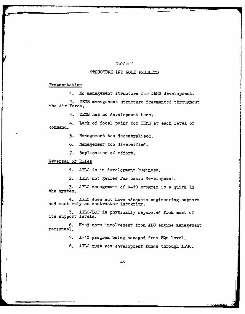
problems. These problems are listed in Tables I through
3, respectively. The problems that did not fit into one
of these major areas were not classified and were analyzed
separately as they related to the major problem areas.
Structure and Role Prblems
Interview respondents identified structure and
role problems which were classified into two major areas:
(1) the fragmentation of TENS management throughout the
42
_________________
04
E4
0
44
opS
RyS
go14014 04
LEGEND FOR FIGURE 4
A RDP monitors 1-10 TEMS program development but has nodirect involvement.
B LET coordinates with Congress for the A-10 TES pro-gram authorization and funds appropriation (PMD).also monitors the A-10 TEMS program for logisticsaspects of engine maintenance.
C AZDC developed the A-1O/TF34 TEMS maintenance hand-book. They also did gas path analysis studies.
D AFLC/LOP determines engine management informationrequirements and furnishes this to CEIS. CEMS isusing information requirements generated by LOP toassist in the development of CIS Increment IV.CZS is using A-10 T2S as a prototype for IncrementIV.
E LO CLIS has a contract with ARtlNC concerning therequirements for CEMS Increment IV.
F Lero Propulsion Lab has furnished informationconcerning Maintenance Information Management System(MIMS) interface and data flows. Also, developedsoftware algorithms.
G Systems Control, Inc. (SCI) was under contract forturbine engine fault detection and isolation algo-rithms. Also, SCI analyzed the engine informationrequirements for the various engine management andmaintenance levels.
H San Antonio AIX was supporting the L-10 TIMS programtest. The program test director, contracting officer,and engineering support were located there.
I Myrtle Beach AFB was the field location for the A-10TMIS program test. A-10 aircraft and personnelassiged to Myrtle Beach AFB participated in theprogram test.
Z HQ TAC provides inputs to LOP as to TEMS requirementsand applications for the A-10 aircraft.
K YZL monitors the A-10 TMIS program for logisticalconsiderations. YZL currently has no other directrelationship with LOP.
L ASD/fZE has provided engineering software support,and data reduction for the A-10 TEMS program.
M LOP inputs ATLC requirements for F-100 EDS andGeneric TEIS programs. YZN and LOP share lessonslearned and program -developments on an informalbasis.
N AX monitors A-10 TIMS program to ensure avionicsstandardization.
0 The SAB periodically reviews the A-10 TMIS program.They make suggestions and recommendations for programimprovement.
AA HQ USAF/RDP monitors all TMIS programs including F-I0EDS and Generic TEKS.
BB HQ USAF/=E monitors P-lO0 EDS and Generic TESprograms for logistical aspects of engine maintenance.L also coordinates TES user requirements withCongress to receive ERT~s.
CC AX monitors the F-100 EDS and Generic TES programsto ensure standardization of avionics.
DD TZL ensures that logistics elements are consideredfor F-l0 EDS and Generic TMIS programs.
E LOP provides inputs to TZN concerning TElS require-ments for new engines. LOP and YZN also have aninformal sharing of lessons learned and programdevelopment.
FF AFLC/LOP determines engine management informationrequirements and provides this to CES. CEMS usesthese requirements to assist in developing CEMSIncrement IV. C12S is using the A-l0 TEKS programas a prototype for CEMS Increment IV.
GG Langley AFB, VA is the location of the F-O0 EDSoperational test program using F-15 aircraft and TWGmaintenance personnel.
H HQ TAC provides inputs to YZNT concerning requirementsand application of the F-10 EDS. All MAJCOkls provideinputs to 1W concerning requirements and applicationsfor the Generic TEMS.
II YZE provides engineering support to YTZ for F-l0 EDSand Generic TEMS programs.
JJ All aircraft SPOs direct engine health monitoring/diagnostic matters to YZN.
EX MCAIR is the primary contractor for the F-1O0 EDSprogram.
LL The Aero Propulsion Lab is providing research anddevelopment efforts to develop fault detection andisolation algorithms for turbine engines. They arealso engaged in diagnostic research and developmentfor the F-l01 engine which may have an applicationfor the Generic TMS program.
MM SCI was contracted to develop fault detection andisolation algorithms for turbine engines. SCI alsoanalyzed engine information requirements for thevarious management and maintenance levels.
N The SIB periodically reviews the P-lO0 EDS and Generic= programs. They make suggestions and recommenda-
tions for program improvements.
46
Table I
STRUCTURE AND ROLE PROBLEMS
Fragmentation
1. No management structure for TENS development.
2. TENS management structure fragmented throughoutthe Air Force.
3. TENS has no development home.
4. Lack of focal point for TENS at each level ofcommand.
5. Management too decentralized.
6. Management too diversified.
7. Duplication of effort.
Reversal of Roles
1. AFLC is in development business.
2. AFLC not geared for basic development.
3. AFLC management of A-10 program is a quirk inthe system.
4. AFLC does not have adequate engineering supportand must rely on contractor integrity.
5. AFLC/LOP is physically separated from most ofits support levels.
6. Need more involvement from ALC engine management
personnel.
7. A-10 program being managed from HQs level.
8. AFLC must get development funds through AFSC.
47
Table 2
INTEGRATION AND INFORMATION FLOW PROBLEMS
Competition
1. Organizations looking and fighting for money
to finance their own TENS programs.
2. Competing for recognition and dollars.
3. Unhealth competition between AFLC and ASD.
4. Competition and politics involved.
Crossfeed
1. No feedback for lessons learned. No crossfeed.
2. Agencies involved are not aware of what isgoing on in other agencies.
3. ALD representatives in YZN are not beingadequately informed about the A-10 program.
4. CES relates to ASD through LOP. No direct
coordination.
5. Need better coordination between LOP and YZN.
Interface
1. Failure to look at overall system. Everyorganization working on its own problems and looking atown piece of the pie.
2. No integration/standardization between TEMSprograms.
3. Need better organizational interface.
4. ALD still learning interface Job, and needsto do a better Job of coordination and integration.
48
5. ALD needs to be more involved at all management
levels.6. Good cooperation, but clumsy and hard to manage.
7. ALC, ASD, and users need to work togetherbetter.
49
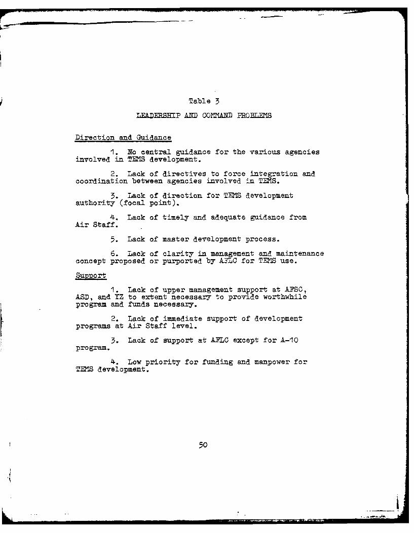
Table 3
LEADER SP AM COMMAIND PROBLEMS
Direction and Guidance
1. No central guidance for the various agenciesinvolved in TENS development.
2. Lack of directives to force integration andcoordination between agencies involved in TENS.
3. Lack of direction for TENS developmentauthority (focal point).
4. Lack of timely and adequate guidance fromAir Staff.
5. Lack of master development process.
6. Lack of clarity in management and maintenanceconcept proposed or purported by AFLC for TENS use.
Support
1. Lack of upper management support at AFSC,ASD, and YZ to extent necessary to provide worthwhileprogram and funds necessary.
2. Lack of immediate support of developmentprograms at Air Staff level.
3. Lack of support at AFLC except for A-10program.
4. Low priority for funding and manpower forTEES development.
50
_____
.4
Air Force, and (2) the reversal of normal, assigned roles
by those involved in TENS development. (See Table I on
page 47).
The problem of fragmentation was viewed and
expressed in several different ways. The respondents
indicated that the management st';ructure for TENS develop-
ment was somewhere between non-existent and too diversified
or decentralized. As was shown in the basic structure,
numerous agencies are involved with TENS development.
Although ASD/YZN and AFLC/LOP were identified as the two
central agencies in TIS development, TENS management was
seen as fragmented or spread between many other Air Force
organizations.
Closely related to the fragmentation problem was
the problem of reversed and unclear roles. Much of the
fragmentation appeared to be caused by the lack of clarity
for authority and specific roles for TEMS development.
Each organization was autonomous to some extent and to
some degree determined its own role in TEIS development.
As brought out in the interviews, the most obvious example
of the role change is ALC's involvement in TENS devel-
opment. With AFLC assuming a development role which is
normally assigned to A-SC, several other problems were
encountered. The interviews indicated that ALC is not
suited or tasked for basic development and lacks adequate
51
engineering support. Therefore, AFLC has had to depend on
contractors and ASD for A-1O TS engineering support.
However, for ASD to provide support, funds must be budgeted
for use in this capacity. Also, funds for any development
undertaken by AFLC must be provided by AFSC since no
development funds can be legally budgeted for AFLC. In
addition to these problems, AFLC/LOP is an headquarters
level organization managing the A-10 program and is
physically separated from most of the support levels within
AFTLC such as the ALCs. Normally, headquarters set policies,
and the divisions such as ALC run the programs.
This fragmentation of the management 9tructure and
reversal of roles among organizations has led to dupli-
cation of effort and no central agency to coordinate TEMS
development and monitor all the various TEMS efforts and
related activities. Therefore, good communication,
cooperation, coordination, and integration between these
agencies are required.
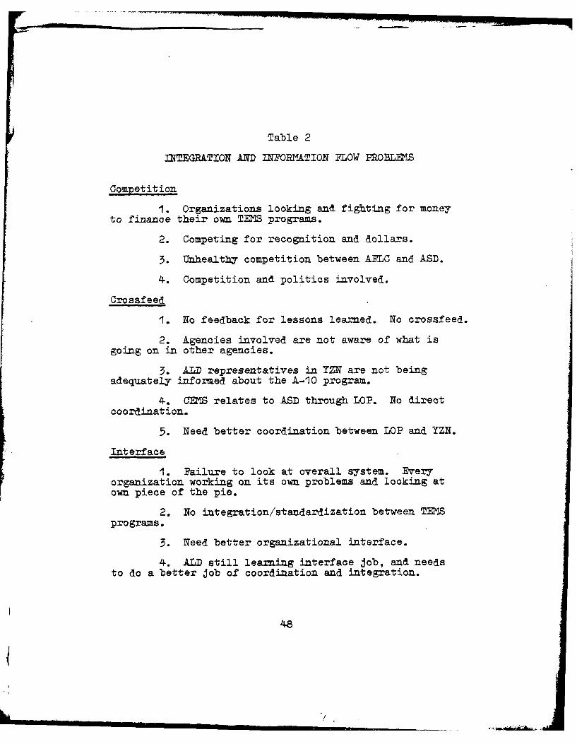
Integration and Information Flow Problems
Integration and information flow among the various
parts of a decentralized organization is critical to
effective and efficient operations. TENS development for
the Air Force is faced with a number of problems in this
critical area. The problems revealed in the interviews
52
were grouped into three sets: (1) competition between
agencies, (2) lack of information crossfeed between agencies,
and (3) lack of integration and interface between agencies
involved in TMS development. (See Table 2 on page 48).
The competition problem was viewed as being very
subtle and below the surface. This problem was not readily
apparent to the interviewers but was apparent to those
involved with TEMS. The underlying cause went back to the
fragmentation and role conflicts of the agencies involved.
TENS development requires manpower and money, both of which
are limited resources. The competition between AFLC and
ASD was also influenced by AFLC's immediate need for a
tool to provide better support for OCN whereas ASD is more
concerned with performance and cost. This immediate need
led AFLC to undertake the A-10 program. The underlying
competition between AFL( and AFSC for money, manpower,
and recognition for their programs has contributed to a
lack of information flow and integration between agencies
involved in TENS development.
The limited information flow between agencies was
reflected by the set of problems listed under crossleed.
The most prevalent area of concern voiced was the lack of
crossfeed and information flow between CENS and YZN. In
general, most of the information flow between any of the
53
agencies was very informaal, and many of the agencies felt
they lacked adequate knowledge about the activities,
progress, successes, and failures of other agencies
involved in TENS development.
The final set of integration problems was clas-
sified under Interface. There were several aspects to
these interface problems. One was a failure of the
agencies working on TENS development to look at the over-
all system. Each agency had a tendency to concentrate on
its own problems and not worry about integrating with the
other agencies and their problems. The result has been
no integration and standardization among TZNS programs
due to this lack of organizational interfacing. Although
most of the respondents felt that genuine efforts for
cooperation were put forth, this cooperation was clumsy
and hard to manage.
The other aspect of the interface problem concez~ed
the role of AFALD. Some respondents indicated that as
AL representatives in ASD become more experienced in
their interface role, coordination, communication,
and integration between Apr and ASD would improve. These
respondents also felt that AwD needed to be more involved
in TENS integration at higher management levels.
54.
2__
Leadership and Command Problems
The leadership and command problems identified were
divided into two areas: (1) lack of adequate direction or
guidance, and (2) lack of adequate support for TENS devel-
opment. (See Table 3 on page 50).
The interviewees perceived a lack of direction and
guidance in several areas of TENS development. First, the
various agencies involved were not provided central
guidance as to the goal of TENS development as it relates
to each of the agencies. The second area lacking was
directives for integration, coordination, and a focal point
or authority for TENS development. Guidance in this area
was seen as needed in order to provide clear definitions
of roles to reduce role conflict and ambiguity. Although
Air Staff monitored the TENS programs, it had very little
direct involvement and provided very little written
direction. Another problem was the lack of a master
development process for TENS. In addition, before direc-
tion for TENS development could be given, the problem of
each agency not clearly understanding the management and
maintenance concepts for which TEMS is a tool should be
resolved.
The lack of support problem seemed to be pointed
mostly at upper level managers at AFSC, ASD, and YZ, who
55
were not convinced that TENS is a necessary tool for OCM
or that it will reduce the high cost of engine support.
Although interest in TEMS was apparent at Air Staff,
interviewees felt that no immediate support for development
programs was available in order to ensure necessary funding.
Some respondents also perceived a lack of support in AFLC
except for the A-1O program. However, to the interviewers,
AFLC seemed to be the biggest advocate of TENS development
for all new aircraft engines. As a result of this lack of
support, TEMS suffers from a low priority for funding and
manpower.
Other Problems
The remaining problems that appeared significant
were grouped into three areas: (1) Personnel, (2) Conti-
nuity, and (3) Incentives. These problems are listed in
Table 4.
PROPOSED STRUCTURES
The structured interview guide (Appendix) elicited
suggestions for overcoming the TENS management problems
perceived by each respondent. Several ideas for improve-
ment of the organizational structure and roles for Air
Force management of TEMS were recommended. Based on the
problem analysis and the suggested structure and role
56
Table 4
OTHER PRO BLEMS
Personnel
1. Lack of experienced personnel in diagnostics.
2. Lack of nucleus of personnel from systemsdevelopment standpoint.
3. Lack of overall expertise in diagnostics.
4. Lack of electronics engineers in YZ.
5. Organizations involved have limited manpower,time, and money to learn or teach technology.
Continuity
1. Lack of continuity and stability in personnel
expertise and assignments.
2. Lack of consistency in support for TENS.
3. Lack of focal point for TENS across each levelof management in each organization.
4. Degree, dedication, and stability for TENSdevelopment in each organization is different.
5. More than one "pusher" and expert needed ineach organization.
Incentives
1. Incentive low for SPO Director to considerTENS for new aircraft.
2. Lack of emphasis from command levels to pushSPOs to use proven parts of TENS technology.
3. SPOs are evaluated on cost, schedule, andperformance for which TENS could be a liability.
57
changes, four proposals were formulated with each proposal
including three key elements: (1) an organizational struc-
ture, (2) an assignment of roles for key agencies, and
(3) lines of interorganizational communication.
Another set of interviews were conducted to solicit
comments concerning the advantages and disadvantages of
each proposal. A brief description of each proposal and
the advantages and disadvantages identified by the respon-
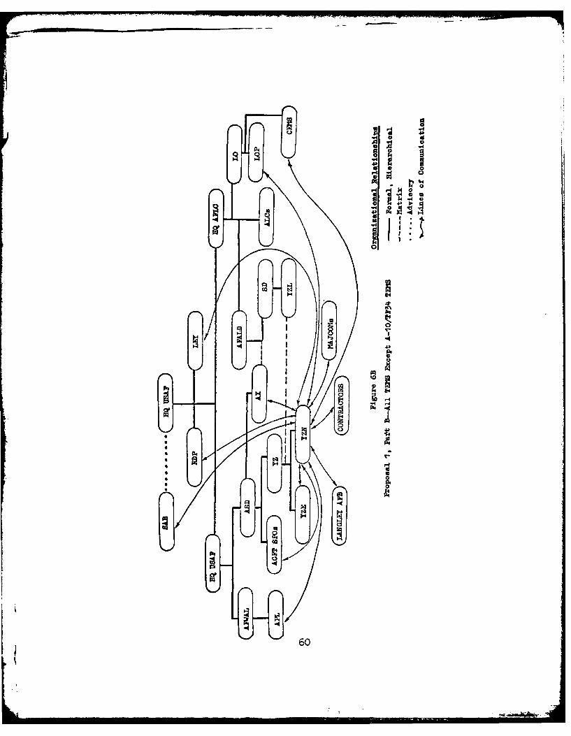
Proposal I essentially left the existing management
structure unchanged while allowing AFLC/LOP to continue
with the A-10 TEMS Program to completion. This proposal
would also designate YZN as the single Air Force focal
point for all TElS development and acquisition programs
except the A-10/TF34 TEMS. This proposal is depicted in
Figures 6A and 6B.
The major advantage identified in this proposal
was that a single focal point for all TENS development
would be established after the A-10 program is completed.
Another advantage recognized was the possible benefits
that could be derived from the testing and proliferation
of two different approaches to TES development. In some
cases competition could lead to greater efficiency and a
58
00
0-44
040
ta4
ca4
590
LOA0
4.14
44
600
better system if information concerning successes, failures,
and lessons learned is shared. Stagnation of ideas may be
avoided and new ideas encouraged.
Several disadvantages for this proposal were pointed
out by the interview respondents. Prior to completion of
the A-10 program, the organizational structure, role, and
,.nterface problems identified in the present management
structure would not be resolved. AFLC would remain in
development for the A-10 TEMS and would still be competing
with ASD for recognition and limited funds. Several other
problems relating to AFLC acting in a development role
would likely continue. Fragmentation and duplication of
effort would be encouraged. The feedback and crossfeed
problems for information and lessons learned would not be
solved. In addition, the perceived lack of support at
upper management levels of AMC, ASD, and YZ could hamper
the TENS effort within YZN. Manpower was already critical
and any further reductions could have a devastating effect
on TENS development and application.
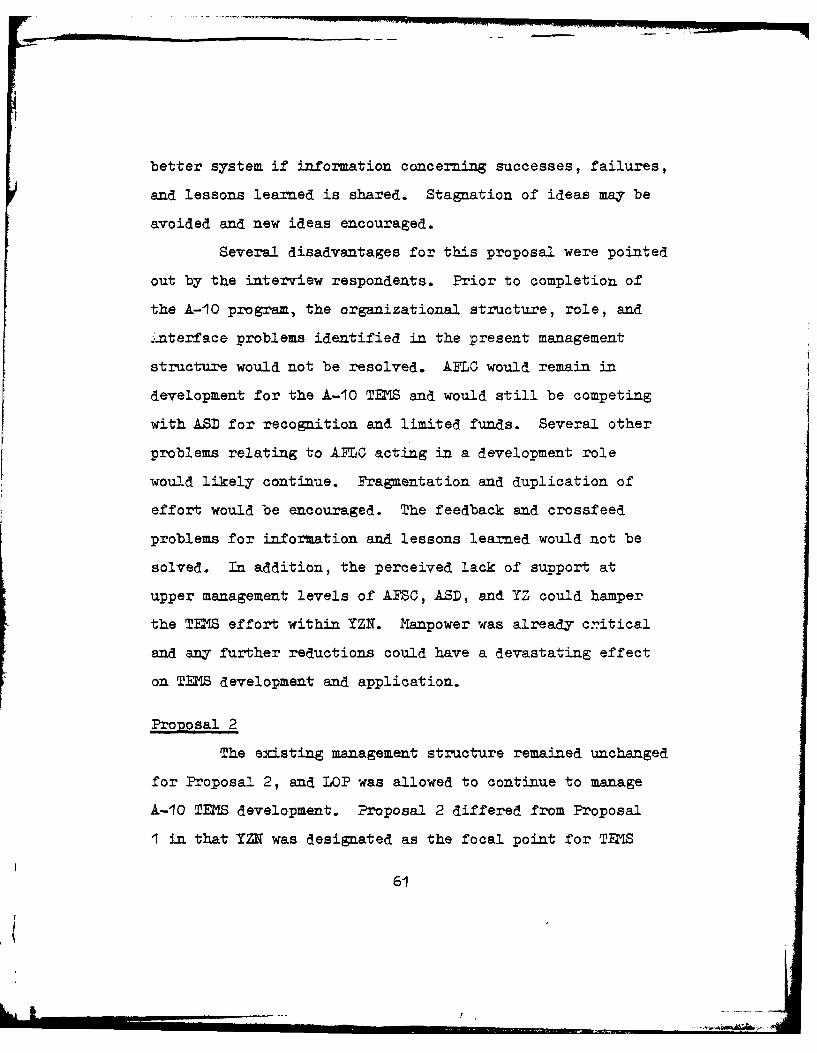
Proposal 2
The existing management structure remained unchanged
for Proposal 2, and LOP was allowed to continue to manage
A-10 TEMS development. Proposal 2 differed from Proposal
1 in that YZN was designated as the focal point for TES
61
J t, -T -- Ili l I III II Ill ........ . ... '.' ! ~ *
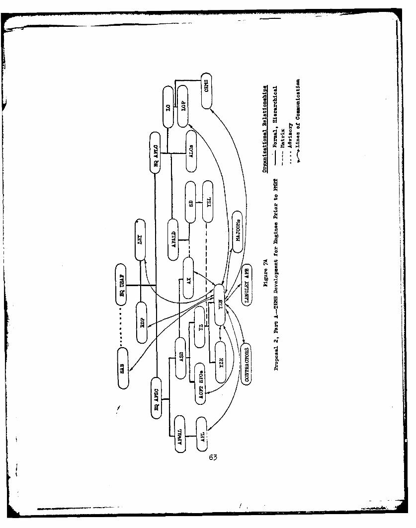
development for all new engines that had not completed
P RT. LOP was designated as the focal point for development
of TEIS after the engine had been transferred to AFLC. This
proposal is depicted in Figures 7A and 7B.
Some respondents indicated that a possible advantage
of Proposal 2 would be more priority, support, and respon-
siveness to the TEMS needs for older engines. This opinion
was based on the perception that, for older engines, ASD/
YZN would have lower priority and support of TENS than
would AFLC/LOP.
In addition to the competition and integration
problems discussed earlier, several disadvantages were
identified. The most significant problem in the eyes of
the respondents was that AFLC would remain in the develop-
ment arena. Also, if this proposal was implemented, the
ALCs, rather than LOP, were recognized as being more
capable of acting as a development focal point for old
engines. However, ASD was seen as the agency with the
expertise and assigned role to develop new systems. The
shortage of engineers Air Force-wide was identified as
another disadvantage which further endorsed the case for
ASD with its locus of engineers to remain as the single
focal point. The concept of two developers also defeats
the concept of generic TENS.
62
t/
424
-C4)
C-4
M 4 p
L P,
634
o 14 3
00
E-4
I0
q *
II.
Proposal 3
This proposal would establish a new office under
ASD/YZ which would be responsible for all TENS development
and acquisition matters Air Force-wide including the A-10
TEM program. This office would not be a subunit of YZN
but would report directly to YZ. The remainder of the
management structure would be the same as that for
Proposals I and 2. Lines of communication would be as
indicated in Figure 8. It is recognized that a great
deal of interorganizational communication would go through
formal, hierarchical channels. For purposes of simplicity,
lines of communication have been purposely drawn between
ultimate sender and receiver agencies.
Respondents identified several probable advan-
tages and disadvantages associated with management of TENS
under Proposal 5. Advantages cited were that this proposal
would:
1. Facilitate definition and clarification ofAir Force requirements and goals for TEMS.
2. Provide centralized planning, programming,budgeting, coordination, control, and policy making forall TENS development and acquisition.
3. Provide better interorganizational communi-cation.
4. Establish TENS priorities to resolve conflictscreated by differing suborganizational goals.
65
" I I . n ,. - -- / ,--
I,0
big
kl 4
0
IDI
I n8
* 7I
5. Provide a systematic approach to TENS manage-ment problems rather than allowing a piecemeal approach.This could enhance system interfaces.
6. Control TENS hardware and software proliferationby ensuring standardization where practical.
7. Provide a single point of contact for MAJCOMs,sister services, allies, contractors, etc. This wouldenhance the application of lessons learned.
8. Provide added emphasis and concentration ofeffort (specialization) on TENS by separating YZ/TIMSfrom YZx.
9. Permit greater TENS program visibility at theAir Staff and Congressional levels to facilitate fundsappropriation.
10. Probably result in lower total dollar costs
than otherwise.
Respondents suggested that management of TENS
under Proposal 3 would have the following disadvantages:
1. The YZ/TEMS organizational concept may be toonarrow to warrant a separate office dedicated only to TENS.
2. The present priority placed on TENS by ASDmay not be high enough to justify a separate office.
3. Resources used for TENS will decrease resourcesavailable for other programs.
4. Since ASD's primary concern is not support-ability, YZ/TEMS may lack an appreciation as to AFLC anduser needs and requirements for TENS. This may beparticularly true for older engines (engines after PM).
5. Absorption of the A-lO TENS program by YZ/TEMSmay cause behavioral problems for AFILC personnel involvedwith the A-l0 TENS program.
6. Benefits gained by competition between theA-l0 TENS and F-l0 EDS programs would be lost.
7. Centralization of TENS efforts may repressfresh ideas concerming TENS. Good ideas may be rejectedor changed to conform to YZ/TENS thinking.
67
I
8. No well-defined relationship exists to clarifyresponsibilities, authority, and procedures to interfaceTES and CEM.
Proposal 4
This proposal would establish a joint AFALD/ASD
Engine Division which would handle all matters relating
to engines (including TEMS). This new organization would
be composed of all the YZ offices, CEMS, LOP, and ALC
representation, as well as other pertinent agencies. This
proposal is depicted in Figure 9. The formal organizational
relationship would be to ASD with matrix relationship to
AFALD. Lines of communication are not depicted since all
necessary agencies would be consolidated into one organi-
zation.
Respondents suggested that management of TEMS under
Proposal 4 would have the following advantages:
1. This cocept would consolidate all enginerelated activities within one organization. This wouldpermit cradle-to-grave management for all engines andprobably reduce engine life cycle costs.
2. This concept would facilitate a more effectiveintegration of engine supportability considerations intoengine system development and acquisition. Long rangeengine supportability would receive a comparable statuswith performance, schedule, and cost criteria since thesame organization would develop, acquire, and supportengines. Therefore, built-in supportability featureswould be enhanced.
3. This may be an effective way to integrateOCM, TEMS, and CEMS.
68
Ix 4
'I
0
43
0
69
I I
I ii
4,
69a
Respondents also suggested that Proposal 4 would
have the following disadvantages:
1. This concept would view the engine subsystemas a system in itself. The engine subsystem may thenexert an excessive influence on the total aircraft systemdesig. thereby decreasing total system effectiveness.
2. ASD/EN is not considered in this proposal.
3. The entire propulsion system needs to beincluded rather than only the engine and its components.
4. Cost and behavioral problems would result fromextensive reorganization.
SUMNAEY OF ANALYSIS
This thesis had two hypotheses: (1) the present
management structure for TZNS development and implementation
is inadequate to meet the needs of the Air Force, and
(2) a single manager concept for TENS would be the most
beneficial approach to the overall management of Air Force
engine monitoring systems. Each hypothesis will be
addressed separately.
Hypothesis I
Analysis of respondents' comments from the
Structured Interview Guide revealed that a highly developed
organizational management structure already exists. This
structure, however, was not designed specifically for
the purpose of managing TENS because TEMS is a relatively
small part of a much larger system. Respondents pointed
70
out that, although a management structure is present, many
problems exist for the development of TENS. These problems
were listed in Table 1, 2, 3, and 4. A closer examination
of respondent comments led to the identification of the
most important problems.
1. Key organizations (AFLC and ASD) have different
perceived needs. AFLC needs to find a solution to the ever
increasing cost of supporting operational systems. While
engines are becoming more and more complex and expensive
to support, personnel experience and ability to support
these systems are decreasing. AFLC views TENS as a pos-
sible solution to these problems because advocates claim
that TEMS can increase operational capability using less
experienced maintenance personnel with lower total support
cost. ASD, on the other hand, needs to produce systems
which meet performance specifications, at a minimum cost,
and on schedule. TENS does not improve performance because
it adds weight, takes up space, and adds more complexity
to the system. TEMS is expensive to develop and acquire
which adds to the total cost of the system. Inclusion of
TENS also decreases the probability that the system will
be developed and acquired on schedule. Although System
Program Directors are required to consider system logistical
support, it is not apparent that supportability is given
equal priorit with performance, cost, and schedule
71
j
criteria. TEMS, therefore, is not perceived as a critical
need by ASD.
2. AFLC is trying to develop diagnostic tools to
more effectively deal with engine supportability needs.
In an attempt to satisfy these needs, AFLC has become the
chief Air Force advocate for the development and acquisition
of TEMS even though their assigned mission does not include
systems development and acquisition. Respondents from
AFLC, ASD, and elsewhere indicated that AFLC has this role
because ASD has not given TEES the support and priority
that AFLC desires. Neither HQ USAF nor HQ AFSC has given
strong support for TMlS. Due to a lack of support from
HQ USAF, HQ AFSC, and ASD, Air Force priority Is relatively
low for development and acquisition of TEMS.
3. HQ USAF has failed to provide formal (written)
policy or guidance which establishes clear lines of
authority, responsibility, and accountability for TEMS
management. Therefore, suborganizational role ambiguity
and role conflict has evolved, particularly between AFLC
and ASD. This lack of leadership from HQ USAF has
encouraged TES management to be operated on a fragmented
basis rather than being treated as an integrated whole.
As such, there is no comprehensive Air Force strategy
for TEKS management. Additionally, there is a general
72
inability to effectively communicate among suborganizations
with different roles.
4. The relationships and interfaces between various
suborganizations are complex, particularly concerning OCM,
TEMS, and CEMS. Although this complexity is a major
problem, there appears to be no structural design or policy
guidance which will force the integration of these inter-
faces.
Although there are major problems associated with
the present management of TEMS, as indicated above, signif-
icant improvements could be made through the existing
organizational structure if HQ USAF would take a more
active leadership role in defining policy, providing
guidance, and clarifying roles for AFSC, ASD, and AFLC
in the development and acquisition of TENS. Weaknesses
in the management of TEMS was primarily due to lack of
support and priority. The organizational structure appears
to be flexible enough to accommodate TEMS development if
adequate support and priority is given by EQ USAF, HQ
AFSC, ASD, and AFALD. The organizational structure can
be improved upon if TEMS receives appropriate support
and priority. Without it, however, there is little to
be gained by changing the organizational structure.
Although the present management structure could be
improved, the analysis shows that the structure is
73
adequate to meet Air Force needs for TEMS development and
acquisition. Therefore, HYpothesis I is rejected.
Hypothesis 2
Respondents commenting in the Structured Inter-
view were nearly unanimous in the opinion that a single
organization should be tasked for the overall management
of TEMS development and acquisition. Some respondents
pointed out that single management of TEMS would risk
sacrificing different approaches which may have yielded
fresh ideas. They also pointed out that competition
between the A-10 TEMS and F-1O0 EDS programs was having
some positive influence on both programs in terms of
efficiency and sharing of lessons learned in two separate
programs.
The advantages of a single organization to manage
TEMS which were mentioned most often included: (1) desig-
nation of a single focal point for all organizations to
coordinate with, get directions from, or address questions
to; (2) goal clarification from a single source; and
(3) centralized management for integrated planning,
programming, budgeting, and control of TEMS. These
improvements were perceived to effect the following changes:
more effective and efficient utilization of resources;
better coordination of effort by reducing role ambiguity
74
and duplication; improved interorganizational communication;
improved interface effectiveness due to leadership, guidance
and communication; elimination of A-l0 TES/F-1O0 EDS
prograx conflicts; and increased assurance of TENS hard-
ware/software standardization. For these reasons Hypothesis
2 was accepted.
75
. T 2, .. . . . .
Chapter 4
CONCLUSIONS AND RECOMDATIONS
MY ISSUES AND CONSIDERATIONS
During the course of the interviews three recurring
issues appeared to have a significant bearing on respondents'
concepts of an appropriate management structure for TENS.
These issues were: (1) respondents' perception of OCM;
(2) cost effectiveness of TEMS; and (3) proper relation-
ships between OCM, TEMS, and CEMS. Conflicting views on
these issues may be the crux of the TEMS management problem.
An additional consideration for standardization is TEMS
avionics classification.
Perceptions of OCM
AFR 66-14 defines OCM as:
the application of inspection and testingprocedures and techniques without removal or dis-assembly that allows the condition of equipment todictate the need for maiutenance or the extent ofrepair required to restore serviceability [14:2].
This definition is rather broad and is subject to
widely differing interpretations. For instance, most
respondents said that it is extremely difficult to practice
OCM without some kind of TEMS. Other respondents indicated
76
that the Air Force has been practicing 0C for years in
the form of the Oil Analysis Program (OAP), Non-Destructive
Inspection (NDI), and borescope. It appears that both
viewpoints have valid arguments depending upon the inter-
pretation of 0CM.
Most respondents agreed that the 0CM concept is
not an either/or proposition but rather a continuum of
various degrees of 0CM implementation ranging from low to
high. Figure 10 depicts this description. According to
the definition in AR 66-14, techniques such as OAP, NDI,
and borescope qualify as 0CM tools. This position was
not questioned by any respondent. However, the consensus
of opinion suggested that the techniques were only a first
step in 0CM implementation and that a more extensive
application of 0CM would require the utilization of a more
sophisticated technique, such as TENS.
Extent of 0CM
I '•I !..
LOW OAP Simple Sophisticated HIGHNBI TEMS TEMS
Borescope
Figure 10
0CM Continuum
OAP, NDI, and borescope are shown to lie on the
lower end of the 0CM Continuum while a simple, relatively
77
unsophisticated TENS would lie somewhat further to the
right. A more sophisticated TENS would lie still further
toward the "HIGH" end of the continuum.
The primary issue is, to what extent does the Air
Force intend to implement OCM? Without this clarification,
suborganizations involved with OC will determine the
extent of OCN which best fits their own needs and desires
without adequate consideration of other suborganizations'
views. This will necessarily result in a lack of goal
congruence and breakdown in effective communication con-
cerning the nature and requirements of OCM.
If OCM concept implementation is to expand, it is
apparent that more advanced techniques, such as TEMS, must
be applied. However, HQ USAF has not clearly communicated
the Air Force's position on this issue.
Cost Effectiveness of TEMS
Past TEMS programs such as the T-38 EEIS and C-5
MDARS, failed to demonstrate the cost effectiveness of
the TMIS concept. Although current TENS programs, such as
A-10 T1S and F-lO0 EDS, have not been fully analyzed, they
also have not clearly demonstrated TENS cost effectiveness.
As the current programs continue to supply operational
test experience, a cost effectiveness determination should
be forthcoming.
78
I I II iS il , ...
Four variables should be considered in the devel-
opment, testing and evaluation of TEMS. These variables
are: (11; 17; 20; 26; 33)
1. TE NS hardware/software complexity,
2. engine sophistication,
3. engine maturity, and
4. the mission environment.
As TEMS increases in sophistication and complexity, it
becomes more costly to develop, acquire, and maintain
related hardware and software. However, an increase in TENS
sophistication creates a greater capability to provide
needed engine health information (see Figure 11). A trade-
off exists between the cost of TENS and the value of the
information it provides. How much TENS sophistication is
enough? The answer to the question is not readily apparent
because there is a great degree of uncertainty as to the
actual value of information provided by TENS. Figure 12
illustrates a conceptual relationship between TENS sophis-
tication and the value of TEMS-generated information. As
TENS sophistication increases, the value of TENS infor-
mation increases up to point B. After B, the value of
information decreases due to information overload. Russell
L. Ackoff gave the following description of information
overload:
79
.S 7 -- S.
4.1a
S
4!
U..
E4Eo C, 0
N ~40
E-4
4o
800
E-4 a: iC, 0 0 *E-1
o P.~ *0
o~ 0.
0
4042
0
0 .4
800
so~
Most managers receive much more data (if notinformation) than they can possibly absorb evenif they spend all of their time trying to do so.Hence they already suffer from information over-load. They must spend a great deal of timeseparating the relevant from the irrelevant andsearching for the kernels in relevant documents. ... Unless information overload to whichmanagers are subjected is reduced, any additionalinformation made available by an MIS [managementinformation system] cannot be expected to be usedeffectively [1 :B1471.
Value ofInformation
DesireaebleIrange ofI
TTNS sophis-Satication
iNeed morel IInfoT o information i Overload
A B C he eree ofTS Sophis -tication
Figure 12
TEIS Sophistication Va. Value of Information
An ideal relationship would match the degree of
TE sophistication with the highest value of TMIS-generated
information. This ideal match would tailor TEMS sophis-
tication. in the range of point A to point C. TEMZ sophis-
tication outside of this range (A to C) would be undesire-
able. k very simple TEMS technique may provide some
81
AD-AO89 365 AIR FORCE INST OF TECH WRIGHT-PATTERSON AFB OH SCHOOL--ETC F/G 1/5AN ANALYSIS OF AIR FORCE MANAGEMENT OF TURBINE ENGINE MONITORIN--ETC(U)UN 80 E G HUBGARD , 6 A SWECKER
UNCLASSIFIED AFIT-LSSR-68-80 NL
2IIIIII
IEhlllEEEllEI
useful information but may not be able to provide all that
is needed. Borescope, NDI, and OAP are possible examples
of this situation. A very complex TEMS may provide too
much information so that needed information is lost or
obscured; the C-5 MI&ABS is a possible example.
The degree of engine sophistication has an impact
on the requirements and nature of a TES. In general,
the greater the degree of engine sophistication, the
greater the need for TEM sophistication. Since highly
sophisticated engines are generally more complex than less
sophisticated engines, the probability for engine malfunc-
tions for a sophisticated engine is higher than that of a
simpler engine. One of the primary purposes for TEMS is
to identify engine component conditions which will lead
to engine malfunction or failure. Once these problems
are identified they can be corrected prior to actual
malfunction/failure. Additionally, if a malfunction/
failure has already taken place, TI4S can be used to
minimize maintenance troubleshooting efforts by isolating
the location and nature of the problem. These functions
become more difficult as engine complexity increases.
Therefore, the benefit potential for TEMS increases as
engine sophistication increases.
The maturity of an engine also has an impact on
the nature and requirements of a TEM. Engine maturity
82
tt
should not be confused with the chronological age of a
specific engine. Naturity refers to the degree of opera-
tional experience for a particular type engine without
regard to the chronological age of a specific engine.
For newly developed engines, acquired knowledge
concerning potential engine problem areas is small. The
phenomenon of infant mortality creates a need to gather
large amounts of information due to the uncertainty of
future engine problems. Some of this information may
become quite useful while some may be relatively useless.
However, knowledge gained through operational experience
with an engine type allows the identification and correction
of built-in defects or weaknesses. This leads to greater
engine reliability and lessens the need for TES. There-
fore, a newly developed engine probably has a greater need
for TENS than does a mature engine.
The fourth TES consideration is the degree of
stress imposed upon the engine due to its operational
environment. Greater environmental stresses will tend to
create or accelerate the occurrence of engine malfunctions
and failures. For example, an engine on a fighter air-
craft is likely to experience more Gs (one G is equal to
the force exerted by gravity on a body at rest and used
to indicate the force to which a body is subjected when
accelerated), higher exhaust gas temperatures, higher
83
sustained revolutions per minute, more throttle bursts,
and higher angles of attack than would a similar engine on
a cargo aircraft. Due to the greater environmental stresses
imposed on the fighter aircraft, it can be expected that
this engine will experience more severe and frequent mal-
functions than would the cargo engine. For this reason,
TIM would have relatively more application for the fighter
engine than for the cargo engine. Consequently, the
operational environment will directly affect the degree
of sophistication and type of TIS needed for a particular
engine/aircraft combination.
It is generally agreed that TEMS sophistication
should be specifically tailored to fit the engine sophis-
tication/complexity, engine maturity, and mission environ-
ment combination. Under or overemphasis on any of these
variables will have a detrimental effect on the effec-
tiveness of TIS. If the T-38 EHS, C-5 MADARS, A-1O
TES, F-100 EDS, or other TEKS programs fail to achieve
a proper mix of the four variables, it would be difficult
to draw meaningful conclusions as to the effectiveness of
TES. Program results should be tempered with an under-
standing of the relationships of these four variables.
Of all the Air Force engine health monitoring programs
and tests to date, only one has had unchallenged success-
84
the SAC Engine Condition Monitoring Program (ECP). In this
program, the four TEMS variables were effectively inter-
related to achieve an estimated cost savings of 20 million
dollars per year (26). Although no TMIS "black boxes" were
used, the TEMS concept was nevertheless applied. The SAC
ECIT stands as an example of how the TEMS concept can be
cost effective.
Additionally, the Scientific Advisory Board (SAB)
cautioned that any cost benefit analysis for TEMS would
be misleading if several intrinsic benefits were not
considered.
TEIS promises to provide the Air Force withintrinsic benefits that cannot be readily quan-tified. Some of these intrinsic benefits includeaccurate recording of data and its automaticinsertion into the Management Information System.This kind of operation avoids transcription errors.A second intrinsic benefit is the increased confi-dence in the ability of the wings to generatesorties when a surge is needed. A third benefitof this kind is that TEMS provides the line main-tenance staff with a better understanding of theengine; hence, in the long term, more efficienttroubleshooting processes will result. A fourthbenefit could be the use of TEMS data for refereepurposes if the Air Force should go to warranty-type procurement. Nevertheless, the cost benefitanalysis will be of little value if the overallsystem issues have not been clarified previouslyand intrinsic benefits taken into account 115:1-2,1-3].
The Air Force position concerning the cost effec-
tiveness of TEMS should consider the appropriateness of the
four previous mentioned variables as well as the intrinsic
85
!(
benefits of TENS. Failure to do so may effectively delay
or destroy a potentially powerful management tool.
The Interzelationships of 0CM, TENS, and CEMS
If 0CM is viewed as a continuum (see Figure 10),
and the goal is to move outward on this continuum to a
more extensive level of 0CN, the use of TENS appears to be
a necessity. To respond to 0CM requirements, the degree
of TENS sophistication should be determined by engine
sophistication, engine maturity, and the mission environment.
Regardless of sophistication, however, overall TENS effec-
tiveness will largely be determined by the ability of CENS
Increment IV to integrate TENS-generated information into
the management information system.
For example, consider a situation were TENS is
effective in collecting relevant information in the
appropriate quantity, quality, format, and time frame,
and CEMS is unable to integrate this data into the engine
management information system. In this case, engine
managers above the flight line and intermediate maintenance
levels will have little use for TENS and the potential
benefits of TES-generated information will be substantially
diminished. Figure 13 depicts four potential situations
resulting from TZMS/CES interrelationships. Obviously,
the ideal situation would be an effective TENS and an
86
effective CE8. Outcomes in all other quadrants are
undesireable especially when both TES and CEMS are inef-
fective.
EFFECTIVE INEFFECTIVETE.S TENS
Effective RelativelyEFFECTIVE Application of ineffective
C3= application of applicationOCM concept. of OCM con-
cept.
Figure 13
OCK, TEMS, CES Effectiveness Grid
OCM, TES, and CES appear to be highly inter-
dependent, and a change in any one will necessarily
influence the other two. Also, the interface between TEMS
and CEKS appears to be especially critical to the success
of On Condition Maintenance application. Due to the nature
of these interdependencies, OCM, TES, and CEKS should be
viewed and managed as an integrated system rather than as
separate entities. Currently, the management structure
has not been modified to deal with this problem in an
integrated fashion, and HQ USAF has failed to state a
position on this issue. 87
TEMS Avionics Consideration
A TEMS consists of four basic parts: (20)
1. sensors and wire bundles,
2. hardware (electronics),
3. software, and
4. ground support equipment.
AF 800-28, Air Force Policy on Avionics Acquisition and
Support, defines avionics as:
All the electronic and electromechanicalsystems and subsystems (hardware and software)installed in an aircraft or attached to it.Avionics systems interact with the crew or otheraircraft systems in these functional areas:communications, navigation, weapons delivery,identification, instrumentation, electronic war-fare, reconnaissance, flight controls, enginecontrols, power distribution, and support equip-ment [32: para 1 -1].
If TES is identified as avionics, ASD/AFALD AX should have
a direct relationship in developing an Air Force master
plan for TENS acquisition, modification, support and
standardization (32para 1-5). If TES is not totally
avionics, at least some portions of it should be classified
as avionics. In any event,the TES role of AX needs to be
clarified.
TEMS TASK FORCE (TTF)
Regardless of the eventual management structure
for TEMS, there is a need for an organizational vehicle to:
88
1. define the overall purpose and goals of TEMS;
2. clarify responsibilities and authority of eachsuborganization involved with TENS;
3. establish clear lines of interorganizationalcommunication on matters relating to TENS;
4. ensure integrated short and long term planningto achieve the overall goal of TEMS;
5. establish a more specific definition of 0CMwhich means the same thing to all organizations;
6. address the cost effectiveness issue of TMS;
7. define proper relationships among 0CM, TENS,and CENS concepts; and
8. define the TENS role for ASD/AFALD AX con-cerning avionics standardization.
No individual or suborganization is likely to have
the knowledge, understanding or skill necessary to effec-
tively deal with all of these issues. A collection of
representatives from each of the TEMS-related suborgani-
zations is necessary. Suggested representation for this
group (to be called the TENS Task Force (TTF)) should
include the following:
1. YZ Engine Supportability (explained on page 91),
2. YZL,
3. YZE,
4. LOP,
5. CEMS,
6. NAJCOMs,
89
7. Aero Propulsion Lab,
8. AFALD, and
9. ALCs.
This task force should be chaired and directed by one of
the following: Director for Engine Supportability, HQ
USAF/RDP, HQ USAFIE!, or AFALD. HQ USAF should charter
one of the aforementioned agencies to establish a task
force by providing adequate funds, personnel, and authority
to ensure task completion. Initially the TTF should be
given a specified period of time to accomplish its assigned
purpose. A final report should be prepared by the TTF
Director and coordinated to appropriate organizations for
information and/or action.
MODIFIED PROPOSAL
Each of the four proposed structures was considered
as an alternative solution to the TEMS management problem.
Respondents evaluated all four proposals and provided
comments on the acceptability of each. All but one of the
respondents was of the opinion that Proposals I and 2 were
inadequate management structures. The primary reason for
this position was the general objection to an AFLC role in
development, test, and acquisition because this role is
assigned to and best performed by AFSC.
90
All respondents acknowledged that there were
potential advantages to Proposal 4; however, all but one
indicated that the disadvantages far outweighed the
advantages. The primary objection was the possibility
that the engine subsystem would exert an excessive
influence on the total aircraft system which could cause
a reduction in the mission effectiveness of the overall
aircraft system; not unlike the "tail wagging the dog"
syndrome. For this reason Proposal 4 was also rejected.
Proposal 3 was preferred over all other proposals.
However, nearly all respondents felt that TEMS was too
narrow in scope to warrant a separate office on the same
level as YZN. Most respondents also felt that this
structure was doomed to failure due to the present lack
of priority and support given to TENS by HQ AFSC and ASD.
For these reasons Proposal 3 was also rejected.
Although each of the proposals was rejected,
Proposal 3 appeared to offer a partial solution to the
TEMS management problem. For this reason Proposal 3 was
modified in an attempt to retain its advantages and
reduce its disadvantages. The modified Proposal 3,
entitled Modified Proposal, is depicted in Figure 14.
This proposal leaves the structure of Proposal 3 basically
unchanged except for ASD/rZ. Under the Modified Proposal,
a new office of Engine Supportability would be created
91
(
I I 0
lu'
op I
0. 0
04
00
00 0
to k04 E-4 0
92
L N N, , ....
on an equal level with YZN. This office would be respon-
sible for:
1. Ensuring that engine life cycle support con-cepts are developed and considered for integration in newengine development and application for old engines withparticular attention given to the requirements and natureof reliability centered maintenance.
2. Providing program management for all TEFShardware and software development and acquisition. Thiswould include the A-l0 TEMS , F-lO0 EDS, Generic TEMS,and future TEMS programs.
3. Ensuring that TEMS effectively interfaces withthe engine management information system. Particularattention should be given to the TEKS/CEMS interface.
4. Developing and improving other techniques ofengine health monitoring such as borescope, NDI, OAF, ormanual trending.
This proposal has attempted to broaden the scope
of TEMS to include engine supportability in general. This
approach is intended to give greater visibility to engine
logistical considerations in the ASD/IYZ community as well
as to create an improved atmosphere for an effective TEMS/
CEMS interface. Some disadvantages associated with Pro-
posal 3 would still persist. These include ASD priority
and support for TMNS, behavioral problems due to AFLC
losing A-10 TENS management, loss of A-IO TEMS/F-IC0 EDS
competition, and possible stagnation of ideas. The Modi-
fied Proposal was made using the following assumption: HQ
AFSC and ASD will provide adequate priority and support for
engine supportability. Without this priority and support
93
L-
the proposal is meaningless and all identified disadvantages
would likely continue. Therefore, it is incumbent upon
HQ USAF to provide the priority and guidance necessary to
ensure AFSC/ASD support if engine supportability (including
TEMS) is to improve.
RECOMMNIT TION
Based on the findings of this research effort, the
Modified Proposal is recommended as the most practicable
management concept for effectively utilizing TENS for Air
Force engine management. The establishment of a TEMS Task
Force is recommended to enhance the effectiveness of dealing
with present and future problems associated with the devel-
opment of Air Force Turbine Engine Monitoring Systems.
94
. ... L __ , : _ : _ "... . . .. . I I I I - I .... ....'-" " f
I
APPENDIX
STRUCTURED INTERVIEW GUIDE
95
HMdi PAG Wa.Mo.M rzUS9
APPENDIX
1. What is your job title?
2. How long have you been in this position?
3. How many years experience have you had inengine-related fields?
4. What is your role/involvement with the TEMSprogram?
5. What additional involvement does your organi-
zation have with TENS?
6. How long have you been involved in this program?
7. In your opinion, what is the present and futureimportance of TENS?
8. In your opinion, what are the major problemsto be overcome in the TMS program?
9. From your perspective, what is the presentmanagement structure for TRIS development and implemen-tat ion?
10. From your perspective, what other organizationsare involved with TEMS, and how do you perceive their role?
11. How does your role in TES relate to/integratewith other organizations' roles?
12. In your opinion, what problems, if any, existdue to the present TEMS management structure? ,
13. What suggestions do you have for overcomingthese problems?
14. In your opinion, should a single organizationbe tasked with the overall responsibility for TENS? Whyor why not?
96
(I
15. If yes, which organization do you feel wouldprovide the best management for TENS or should a neworganization be created? Why?
16. What problems do you foresee with a singlemanager for TMIS?
17. In your opinion, what changes, if any, shouldbe made in the TES management structure in your organi-zation and in the manner your organization relates to otherorganizations involved with TEMS?
2. Air Force Acquisition Logistics Division, Office ofInformation. "Air Force Acquisition LogisticsDivision." Fact sheet. Wright-Patterson AFB OH,May 1979.
3. Air Force Logistics Command, DCS/Logistics Operations."Comprehensive Engine Management System (CEMS)Executive Summary Data Project Plan (DPP-HAF-D-76-001." Wright-Patterson AFB OH, December 1978.
5. Air Force Systems Command, Aeronautical SystemsDivision. "Engine Condition Monitoring." Video-tape. February 1977.
6. __ _. "Engine Condition Monitoring for Main-tenance." Videotape. September 1977.
7. Birkler, J. L. and J. R. Nelson. "Aircraft TurbineEngine Monitoring Experience: Implications forthe F100 Engine Diagnostic System Program."Unpublished-research report No. R-2391-AF, TheRand Corporation, Santa Monica CA, April 1979.
8. Brady, Captain James F., USAF and Captain Michael J.Scritchfield, USAF. "An Examination of theCurrent United States Air Force Engine ReportingSystem." Unpublished Master's thesis. SLSR9-72B, AFIT/SL, Wright-Patterson AFB Of,September 1976. AD 750910.
9. Capps, Major Ted, USAF. Aircraft Maintenance StaffOfficer, Directorate of Maintenance and Supply,HQ USAF, Washington, DC. Telephone interview.11 April 1980.
99
..... - ---- .,
10. Carlson, Major Robert J., USAF. F-100 EDS and GenericTEMS Program Director, ASD/YZN. "Generic TE1S."Briefing to the USAF Scientific Advisory Board,Al hoc Committee on TEMS, Wright-Patterson AFB OH,16 April 1980.
11. . F-100 EDS and Generic TEMS Program Director,=ZN, Wright-Patterson AFB OH. Personal inter-
views conducted on 16 April and 25 April 1980.
12. Chapman, Captain Jack W., USAF and Captain Charles L.Page, USAF. "An Analysis and Synthesis of EngineCondition Monitoring Systems." UnpublishedMaster's thesis. LSSR 27-79B, AFIT/SL, Wright-Patterson AFB OH, September 1979.
13. Chopin, M. H. Chief, TZS Engineering Branch, ASD/YZE,Wright-Patterson AFB OH. Personal interview.29 April 1980.
14. and Mark S. Ewing. "Turbine Engine Diag-noic Monitoring Systems: A State-of-the-ArtAssessment." Unpublished technical memorandumENJE-T-74-1O, ASD/ENJ, Wright-Patterson AFB OH,July 1974.
15. Covert, Eugene E. Chairman, Ad hoc Committee on TEMS,USAF Scientific Advisory Board. Letter, subj:Detailed Remarks from TENS Meeting of September7 to September 9, 1979 to HQ AFLC. undated.
16. Degrande, Major Joe, Jr., USAF and Major Kenneth E.Eickmann, USAF. "A Study of Turbine EngineMonitoring Systems." Unpublished research report0510-78, Air Command and Staff College, ACSC/EDCC, Maxwell AFB AL, April 1978.
17. Delong, George A. Logistics Management Specialist,Engine Diagnostic Branch, AFALD/rZL, Wright-Patterson AFB OH. Personal interviews conductedon 8 April and 25 April 1980.
18. Hamilton, Keith. Diagnostics and InstrumentationTask Manager, Aero Propulsion Laboratory, Wright-Patterson AFB OH. Personal interviews conductedon 11 April and 2 May 1980.
100
i- V
19. Kohlberg, Major Bernard J., Jr., USAF. Director, OnCondition Maintenance, Directorate of PropulsionSystems, HQ AFLC. "A-1O/TF34 TENS Review."Briefing to USAF Scientific Advisory Board, Adhoc Committee on TENS, General Electric AircraftGroup Facility, Lynn MA, 6 September 1979.
20. . Director, On Condition Maintenance,Directorate of Propulsion Systems, HQ AFLC,Wright-Patterson AFB OH. Personal interviewsconducted intermittently 1 October through19 October 1979.
21. . Director, On Condition Maintenance,Directorate of Propulsion Systems, HQ AFLC,Wright-Patterson AFB OH. Personal interviewsconducted on 10 April and 28 April 1980.
22. Maley, Lieutenant Colonel James L., USAF. DeputyProject Manager, Comprehensive Engine ManagementSystem (C S), DCS/Logistics Operations, HQ AFLC,Wright-Patterson AFB OH. Personal interviewsconducted on 3 April and I May 1980.
23. McDonnell Aircraft Company. F100 Engine DiainosticSstem Hardware and Software Definition Phase.fWC Aq270, St. Louis MO, 15 July 1976.
24. Northrop Corporation Electronic Division. T-Engine Health Monitoring System (EEKS) :-- rdware Demonstration Progamm Final Report. NOET76-206, Palos Verdes Peninsula CA, February 1976.
25. Pettigrew, Lieutenant Colonel James L., USAF. "IsENS the Key to Operational Readiness for LessMoney With On-Condition Maintenance?", Presen-tation to Fourteenth Annual InternationalLogistics Symposium, 1979.
26. _. Deputy Director Engineering and TestDeputy for Propulsion, ASD/YZE, Wright-PattersonAFB OH. Personal interviews conducted on 10 Apriland 29 April 1980.
27. Roadruck, Major Max, UBAF. Chief, IntegratedLogistics Support, ASD/YZN, Wright-PattersonAFB OH. Personal interviews conducted 22 Apriland 29 April 1980.
101
28. San Antonio Air Logistics Center. "Program Orien-tation: Reliability Centered Maintenance."Unpublished training guide, Information Spectrum,Inc. Undated.
29. Small, Les. Acting Technical Area Manager forControls and Diagnostics, Components Branch,Aero Propulsion Laboratory, Wright-PattersonAFB OH. Personal interviews conducted on11 April and 2 May 1980.
30. Technical Cooperation Program. Aeronautics Subgroup.Outlines of Current ilitam- Gas Turbine EngineHealth Monitoring Progra s. TTCP technicalreport HAG-2-77, August 1977.
31. U.S. Air Force. Office of the Inspector General.Report On Inspection of Propulsion Unit Management(FPN 74-06), Norton AFB CA, 19 December 1975.
32. U.S. Department of the Air Force. Air Force Policon Avionics Acquisition and Support. AFR 00-28.Washington: Government Printing ffUice, September1978.
33. Williams, Dr. Benjamin R. Program Director, Compre-hensive Engine Management System (CEMS), DCS/Logistics Operations, HQ APLC, Wright-PattersonAFB OH. Personal interviews conducted inter-mittently from 1 October 1979 to 19 October 1979.
34. . Deputy Director, Directorate of PropulsionSystems, DCS/Logistics Operations, HQ AFLC,Wright-Patterson AFB OH. Personal interview.12 April 1980.
35. Yanker, Jerry. Chief, Logistics Engineering Division,Directorate of Propulsion Logistics, AFALD,Wright-Patterson AFB OH. Personal interviewsconducted on 22 April and 29 April 1980.
B. REATED SOURCES
Air Force Logistics Command, DCS/Logistics Operations."Comprehensive Engine Management System (CEMS)."Briefing to the Assistant Secretary of the Air Force/Financial Management, Wright-Patterson AFB OH, 22 May1979.
102
"Comprehensive Engine Management System (CEMS)."Briefing to USAF/CC, Pentagon, Washington, DC,14 October 1978.
. Concept Certification Documentation for the•CoSprehensiv-e.2 ne management SystemCE$,'
Wright-Patterson AFB OH, I January
Pettigrew, Lieutenant Colonel James L., USAF. DeputyDirector Engineering and Test Deputy for Propulsion,ASD/YZE, Wright-Patterson AFB OH. Personal interviewsconducted intermittently from I October 1979 to19 October 1979.
and Keith Hamilton. Proceedings Seventh AnnualTri-Service Meetings for Aircraft Eng~ie Monitoringand Diagnostics (AS-TR-79-904O). Arnold EngineeringDevelopment Center, Arnold A. TN1, 19 July 1979.
Society of Automotive Engineers Committee E-32. Aero-space Recommended Practice: Gas Turbine Engin--rMonitoring System for Aircraft. Technical reportA1P 1587, Warrendale PA, 1979.
Tecbnical Cooperation Program, Aeronautics Subgroup.Outlines of Current Militarz Gas Turbine EngineHealth Monitoring Programs. TTCP technical report
AMG-2-76, keptember 1976.
TZS Review Group. "Turbine Engine Monitoring System(TRW) Review Group Report." Briefing presented toAFLC/LO, Wright-Patterson AFB OH, 25 May 1977.