51
UNIVERSITY OF OSLO IIR filterdesign Sverre Holm INF34700 Digital signalbehandling DEPARTMENT OF INFORMATICS

UNIVERSITY OF OSLO
IIR filterdesign
Sverre HolmINF34700
Digital signalbehandling
DEPARTMENT OF INFORMATICS
UNIVERSITY OF OSLO
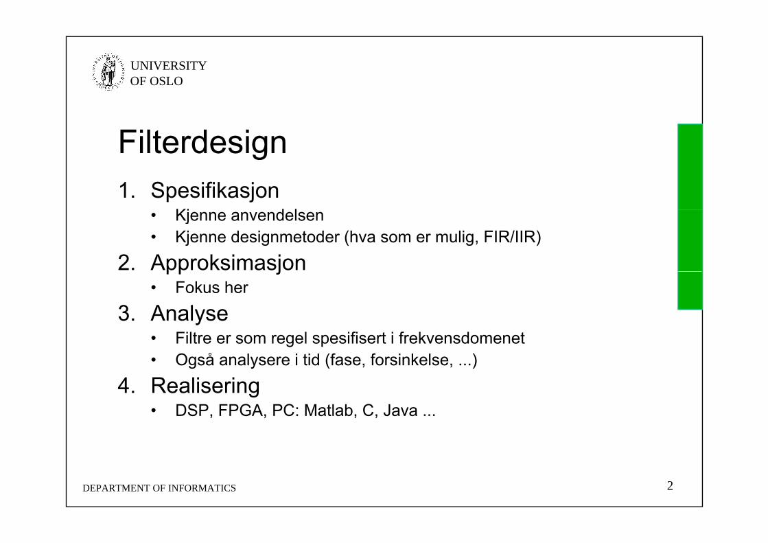
FilterdesignFilterdesign1. Spesifikasjon
Kj d l• Kjenne anvendelsen• Kjenne designmetoder (hva som er mulig, FIR/IIR)
2. Approksimasjonpp j• Fokus her
3. AnalyseFilt l ifi t i f k d t• Filtre er som regel spesifisert i frekvensdomenet
• Også analysere i tid (fase, forsinkelse, ...)
4. Realiseringg• DSP, FPGA, PC: Matlab, C, Java ...
DEPARTMENT OF INFORMATICS 2

UNIVERSITY OF OSLO
SourcesSourcesSourcesSources• The slides about Digital Filter Specifications
h b d t d f lid b S Mithave been adapted from slides by S. Mitra, 2001
• Butterworth Chebychev etc filters are based• Butterworth, Chebychev, etc filters are based on Wikipedia
• Builds on Oppenheim & Schafer with Buck:Builds on Oppenheim & Schafer with Buck: Discrete-Time Signal Processing, 1999.
DEPARTMENT OF INFORMATICS 3
UNIVERSITY OF OSLO
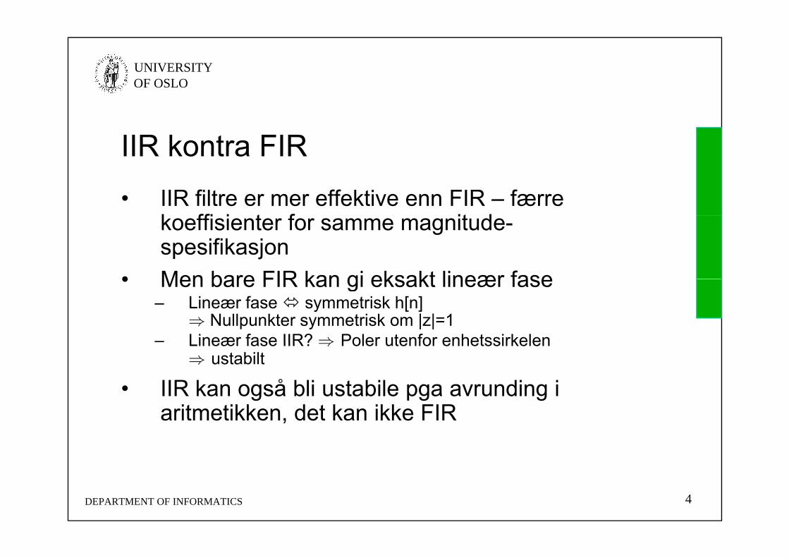
IIR kontra FIRIIR kontra FIR• IIR filtre er mer effektive enn FIR – færre
k ffi i t f it dkoeffisienter for samme magnitude-spesifikasjon
• Men bare FIR kan gi eksakt lineær fase• Men bare FIR kan gi eksakt lineær fase– Lineær fase symmetrisk h[n]
⇒ Nullpunkter symmetrisk om |z|=1– Lineær fase IIR? ⇒ Poler utenfor enhetssirkelenLineær fase IIR? ⇒ Poler utenfor enhetssirkelen
⇒ ustabilt
• IIR kan også bli ustabile pga avrunding i it tikk d t k ikk FIRaritmetikken, det kan ikke FIR
DEPARTMENT OF INFORMATICS 4

UNIVERSITY OF OSLO
Ideal filtersIdeal filtersIdeal filtersIdeal filters• Lavpass, høypass, båndpass, båndstopp
HLP(e j) HHP(e j)
1 1
0 c –c
0 c –c
HBP (e j) HBS(e j)
11– 1
DEPARTMENT OF INFORMATICS 5
–c1 c1 –c2 c2
–c1 c1 –c2 c2

UNIVERSITY OF OSLO
Prototype low-pass filterPrototype low pass filter• All filter design methods are specificed for
l llow-pass only• It can be transformed into a high-pass filter
O i b l d i i i h h• Or it can be placed in series with others to form band-pass and band-stop filters
DEPARTMENT OF INFORMATICS 6

UNIVERSITY OF OSLO
Digital Filter SpecificationsDigital Filter SpecificationsDigital Filter SpecificationsDigital Filter Specifications• As the impulse response corresponding to
h f th id l filt i l d feach of these ideal filters is noncausal and of infinite length, these filters are not realizable
• In practice the magnitude response• In practice, the magnitude response specifications of a digital filter in the passband and in the stopband are given with some acceptable tolerances
• In addition, a transition band is specified between the passband and stopbandbetween the passband and stopband
DEPARTMENT OF INFORMATICS 7
UNIVERSITY OF OSLO
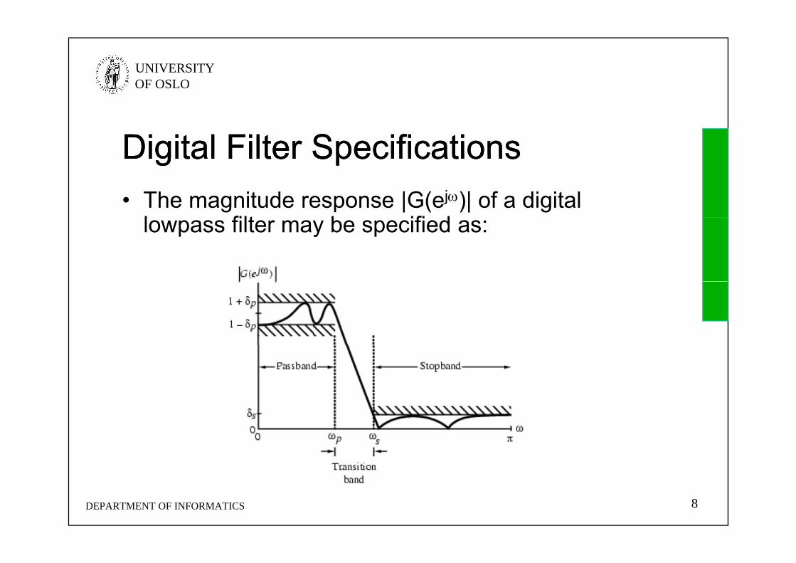
Digital Filter SpecificationsDigital Filter SpecificationsDigital Filter SpecificationsDigital Filter Specifications• The magnitude response |G(ej)| of a digital
l filt b ifi dlowpass filter may be specified as:
DEPARTMENT OF INFORMATICS 8

UNIVERSITY OF OSLO
Digital Filter SpecificationsDigital Filter SpecificationsDigital Filter SpecificationsDigital Filter Specifications• Passband: 0 ≤ ≤ p
– We require that |G(ej)| ≈ 1 with an error ±p, i.e.,
ppj
p eG ,1)(1• Stopband: s ≤ ≤
W i th t |G( j)| 0 ith i
ppp ,)(
– We require that |G(ej)| ≈ 0 with an error s, i.e.,
jeG ,)( sseG ,)(
DEPARTMENT OF INFORMATICS 9

UNIVERSITY OF OSLO
Digital Filter SpecificationsDigital Filter SpecificationsDigital Filter SpecificationsDigital Filter Specifications• p - passband edge frequency• s - stopband edge frequency• p - peak ripple value in the passbandp
• s - peak ripple value in the stopband• Properties:
– G(ej) is a periodic function of – |G(ej)| of a real-coefficient digital filter is an even
function of
• Consequence: Filter specifications are given only for 0 ≤ || ≤
DEPARTMENT OF INFORMATICS 10

UNIVERSITY OF OSLO
Digital Filter SpecificationsDigital Filter SpecificationsDigital Filter SpecificationsDigital Filter Specifications• Specifications are often given in terms of loss
f tifunction: G()=-20 log10|G(ej)| in dB
• Peak passband ripplep = -20log10(1-p) dBp 20log10(1 p) dB
• Minimum stopband attenuationMinimum stopband attenuation p = -20log10(s) dB
DEPARTMENT OF INFORMATICS 11

UNIVERSITY OF OSLO
Digital Filter SpecificationsDigital Filter SpecificationsDigital Filter SpecificationsDigital Filter Specifications• Magnitude specifications may alternately be
i i li d f i di t d b lgiven in a normalized form as indicated below
DEPARTMENT OF INFORMATICS 12
UNIVERSITY OF OSLO
Normalized frequenciesNormalized frequencies• Real values
– Real frequencies: fp, fs, fsample
– Angular frequencies: =2f
• Normalized values• Normalized values– Angular frequencies: =0...2 where fsample 2– Normalized frequencies f=0 ... 2 where 2 is the sampling
frequency (0...1 is the useful range): MATLAB filter design
DEPARTMENT OF INFORMATICS 15

UNIVERSITY OF OSLO
FIR and IIR Digital FilterFIR and IIR Digital FilterFIR and IIR Digital FilterFIR and IIR Digital Filter• Difference equation
Transfer function• Transfer function
– General: IIR - Infinite Impulse ResponseFIR Fi it I l R– FIR - Finite Impulse Response
» N=0, no feedback, always stable
DEPARTMENT OF INFORMATICS 16

UNIVERSITY OF OSLO
Pol- og nullpunktsplasseringPol og nullpunktsplassering• Poler innenfor enhetssirkel Stabil og kausal• Poler og nullpunkter i kompleks konjugerte par Reell• Poler og nullpunkter i kompleks konjugerte par Reell
impulsrespons• Alle nullpunkter finnes speilet om enhetssirkelen Lineær
fase. • Viktig! Lineær fase og reelle koeffisienter Nullpunkter
finnes i grupper av fire.
• Alle nullpunkter er speilbildet av en pol Allpass system• Alle nullpunkter innenfor enhetssirkel Minimum fase
system og inversfilter eksisterer• Alle nullpunkter utenfor enhetssirkel Kausal maksimum
fase
DEPARTMENT OF INFORMATICS 17

UNIVERSITY OF OSLO
DEPARTMENT OF INFORMATICS 18
UNIVERSITY OF OSLO
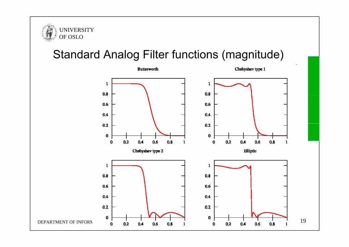
Standard Analog Filter functions (magnitude)
DEPARTMENT OF INFORMATICS 19

UNIVERSITY OF OSLO
Standard Analog Filter FunctionsStandard Analog Filter Functions• Butterworth filter
– no gain ripple in pass band and stop band slow cutoffno gain ripple in pass band and stop band, slow cutoff• Chebyshev filter (Type I)
– no gain ripple in stop band, moderate cutoff• Chebyshev filter (Type II)y ( yp )
– no gain ripple in pass band, moderate cutoff• Elliptic filter
– gain ripple in pass and stop band, fast cutoff
• Bessel filter– no group delay ripple, no gain ripple in both bands, slow gain cutoff
• Linkwitz-Riley filter– Used for crossover filters for loudspeakers
DEPARTMENT OF INFORMATICS 20
UNIVERSITY OF OSLO
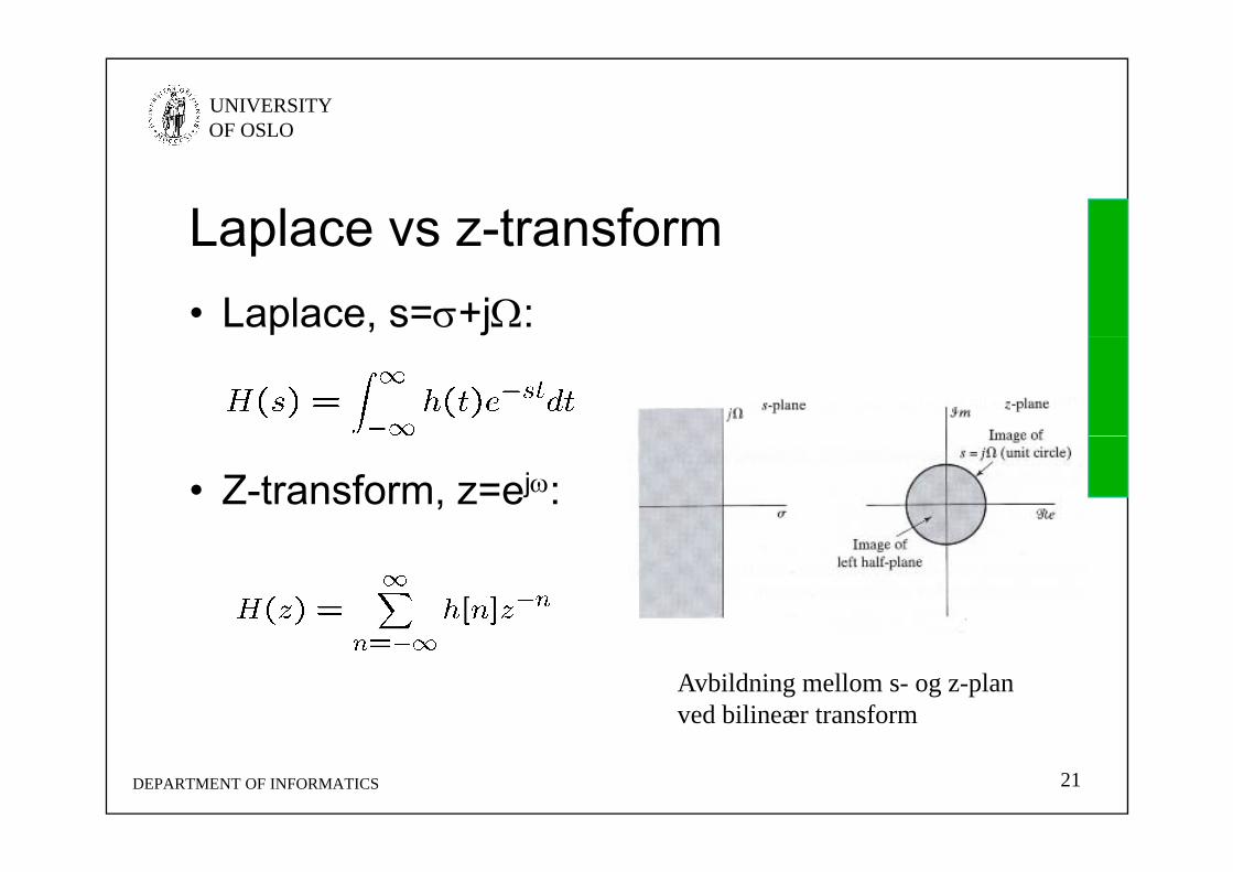
Laplace vs z-transformLaplace vs z transform• Laplace, s=+j:
• Z-transform, z=ej:
Avbildning mellom s- og z-planved bilineær transform
DEPARTMENT OF INFORMATICS 21
UNIVERSITY OF OSLO
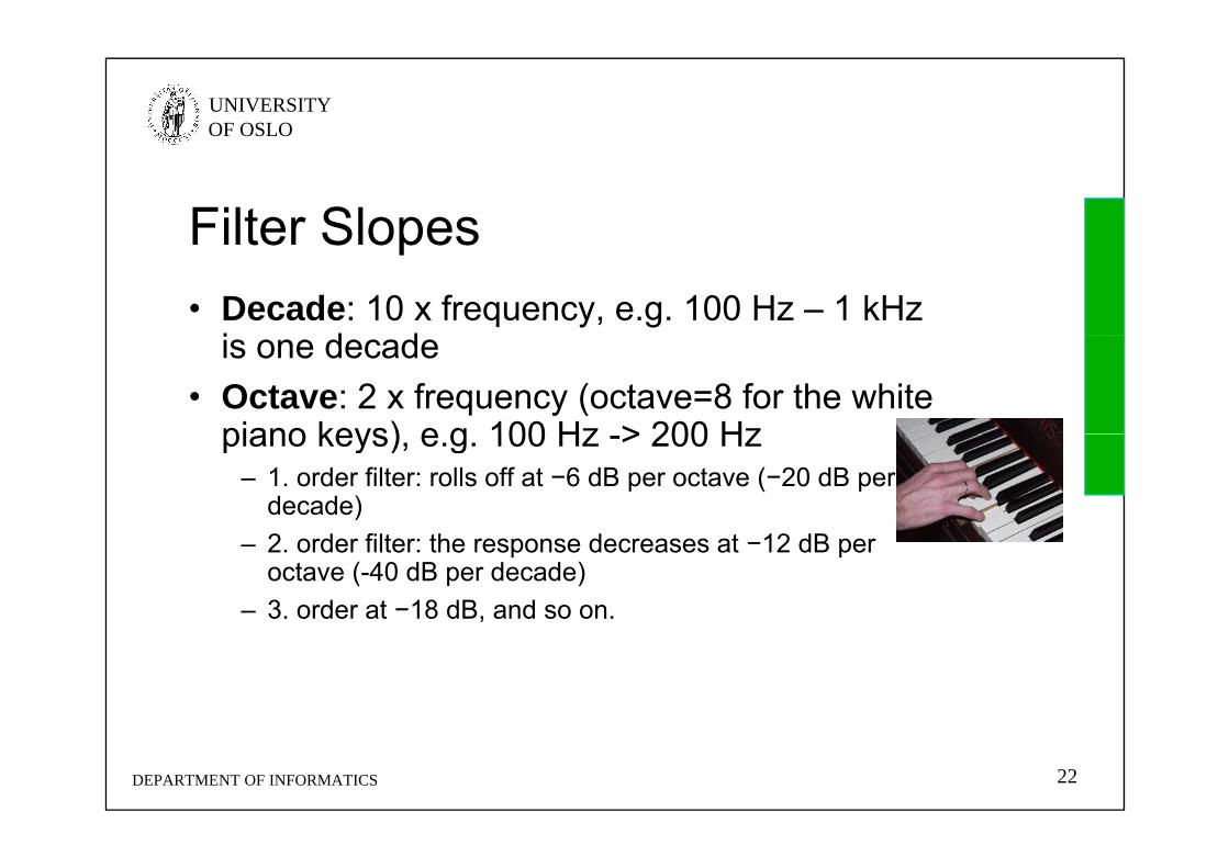
Filter SlopesFilter Slopes• Decade: 10 x frequency, e.g. 100 Hz – 1 kHz
i d dis one decade• Octave: 2 x frequency (octave=8 for the white
piano keys) e g 100 Hz > 200 Hzpiano keys), e.g. 100 Hz -> 200 Hz– 1. order filter: rolls off at −6 dB per octave (−20 dB per
decade) – 2. order filter: the response decreases at −12 dB per
octave (-40 dB per decade)– 3. order at −18 dB, and so on.
DEPARTMENT OF INFORMATICS 22

UNIVERSITY OF OSLO
Group DelayGroup Delay• The group delay is the derivative of the phase
ith t t l fwith respect to angular frequency• It is a measure of the distortion in the signal
introduced by phase differences for differentintroduced by phase differences for different frequencies.
g = -d[arg(H(ej))] / d
DEPARTMENT OF INFORMATICS 23
UNIVERSITY OF OSLO
Butterworth FilterButterworth Filter• Maximally flat (has no ripples) in the passband, and
rolls off towards zero in the stopbandrolls off towards zero in the stopband. • When viewed on a logarithmic plot, the response
slopes off linearly towards negative infinity. • Butterworth filters have a monotonically changing
magnitude function with ω.• First described by British engineer StephenFirst described by British engineer Stephen
Butterworth in "On the Theory of Filter Amplifiers", Wireless Engineer, vol. 7, 1930, pp. 536-541.
DEPARTMENT OF INFORMATICS 24

UNIVERSITY OF OSLO
3 Order Butterworth with =13. Order Butterworth with p 1
DEPARTMENT OF INFORMATICS 25

UNIVERSITY OF OSLO
Plot of the gain of Butterworth low-pass filters of orders 1 through 5.
DEPARTMENT OF INFORMATICS 26Note that the slope is 20n dB/decade where n is the filter order.

UNIVERSITY OF OSLO
Analog ButterworthAnalog Butterworth
3. order passive low passfilter (Cauer topology). ( p gy)
2. order active filter (Sallen-Key topology)
DEPARTMENT OF INFORMATICS 27

UNIVERSITY OF OSLO
ButterworthButterworth• Frequency response:
• Transfer function
• Butterworth polynominals (n even, n odd)
DEPARTMENT OF INFORMATICS 28

UNIVERSITY OF OSLO
ButterworthButterworthn Factors of Polynomial Bn(s)
1 (s + 1)
2 s2 + 1 4142s + 12 s + 1.4142s + 1
3 (s + 1)(s2 + s + 1)
4 (s2 + 0.7654s + 1)(s2 + 1.8478s + 1)
5 (s + 1)(s2 + 0.6180s + 1)(s2 + 1.6180s + 1)( )( )( )
DEPARTMENT OF INFORMATICS 29

UNIVERSITY OF OSLO
Butterworth FilterButterworth Filter• N’th order filter: all derivatives of the gain up
t d i l di th 2N 1’th d i tito and including the 2N-1’th derivative are zero at =0, resulting in "maximal flatness".
• In decibels the high frequency roll off is 20n• In decibels, the high-frequency roll-off is 20n dB/decade, or 6n dB/octave (not only Butterworth – all filters)
DEPARTMENT OF INFORMATICS 30

UNIVERSITY OF OSLO
Chebyshev filterChebyshev filter• Norsk: Tsjebysjeff• Steeper roll-off and more passband ripple (type I) or
stopband ripple (type II) than Butterworth filters. • Minimize the error between the idealized filter
characteristic and the actual, but with ripples in the passband.
• Named after Pafnuty Chebyshev (1821-1894)Named after Pafnuty Chebyshev (1821 1894) Пафну́тий Льво́вич Чебышёв, because they are defined in terms of Chebyshev polynomials.
DEPARTMENT OF INFORMATICS 31
UNIVERSITY OF OSLO
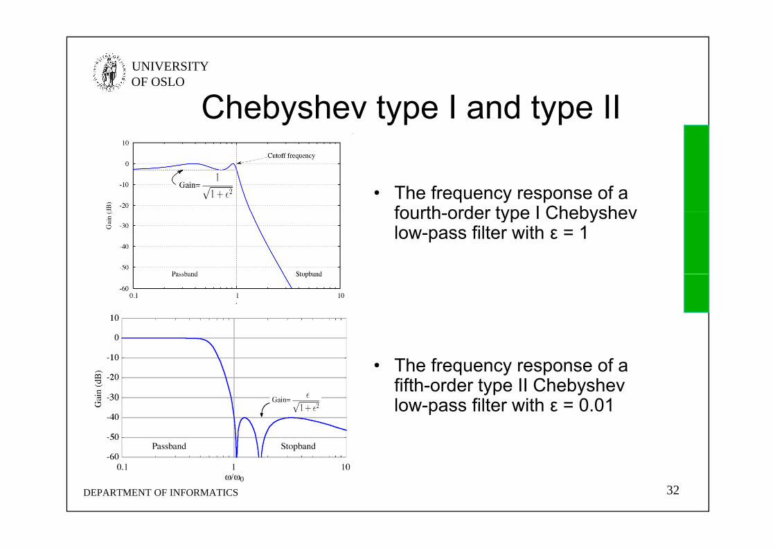
Chebyshev type I and type II
• The frequency response of a fourth order type I Chebyshevfourth-order type I Chebyshev low-pass filter with ε = 1
• The frequency response of a fifth-order type II Chebyshev l filt ith 0 01low-pass filter with ε = 0.01
DEPARTMENT OF INFORMATICS 32

UNIVERSITY OF OSLO
5 Order Chebyshev type I (ε=0 5)5. Order Chebyshev type I (ε 0.5)
• There are ripples in the ppgain and the group delay in the passband but not in the stop band.
DEPARTMENT OF INFORMATICS 33

UNIVERSITY OF OSLO
5 Order Chebyshev type II (ε=0 1)5. Order Chebyshev type II (ε 0.1)
• There are ripples in the gain in the stop band but not in th b dthe pass band.
DEPARTMENT OF INFORMATICS 34

UNIVERSITY OF OSLO
ChebyshevChebyshev• Frequency response (type I, type II)
• ε is the ripple factor, ω0 is the cutoff frequency and Tn() is a nth order Chebyshev polynomial.
DEPARTMENT OF INFORMATICS 35

UNIVERSITY OF OSLO
Elliptic FiltersElliptic Filters• An elliptic filter (also known as a Cauer filter)
h li d i l ( i i l ) b h i ihas equalized ripple (equiripple) behavior in both the passband and the stopband.
• The amount of ripple in each band is• The amount of ripple in each band is independently adjustable.
• No other filter of equal order can have aNo other filter of equal order can have a faster transition between the passband and the stopband, for the given values of ripple (whether the ripple is equalized or not)(whether the ripple is equalized or not).
DEPARTMENT OF INFORMATICS 36

UNIVERSITY OF OSLO
CauerCauer• Wilhelm Cauer (June 24, 1900 – April 22, 1945) was a
German mathematician and scientistGerman mathematician and scientist. • He is most noted for his work on the analysis and
synthesis of electronic filters and his work marked the b i i f th fi ld f t k th ibeginning of the field of network synthesis.
• Prior to his work, electronic filter design was an art, requiring specialized knowledge and intuition. Cauer placed the field on a firm mathematical footing, providing a theoretical basis for the rational design of electronic filters.
DEPARTMENT OF INFORMATICS 37

UNIVERSITY OF OSLO
4 Order Elliptic Filter4. Order Elliptic Filter• The frequency
response of a fourth-response of a fourthorder elliptic low-pass filter with ε=0.5 and ξ=1.05.
• Also shown are the minimum gain in the passband and the maximum gain in themaximum gain in the stopband, and the transition region between normalized frequency 1 and ξ
DEPARTMENT OF INFORMATICS 38

UNIVERSITY OF OSLO
4 Order Elliptic Filter4. Order Elliptic Filter• A closeup of the
transition regiontransition region of the previous plot
DEPARTMENT OF INFORMATICS 39

UNIVERSITY OF OSLO
Elliptic filterElliptic filter• Frequency response:
• where Rn() is the nth-order Jacobian elliptic rational function and ω0 is the cutoff frequency, ε is the ripple factor, ξ is the selectivity factorselectivity factor
DEPARTMENT OF INFORMATICS 40

UNIVERSITY OF OSLO
Bessel FilterBessel Filter• A Bessel filter is a filter with a maximally flat
group delay (≈ linear phase response)group delay (≈ linear phase response). • Analog Bessel filters are characterized by
almost constant group delay across the entire g p ypassband.
• The filter that best preserves the wave shape of filtered signals in the passbandof filtered signals in the passband.
• Named after Friedrich Bessel (1784–1846) as the filter polynomial is expressed with Bessel ffunctions
DEPARTMENT OF INFORMATICS 41

UNIVERSITY OF OSLO
4 Order Bessel Filter4. Order Bessel Filter• A plot of the gain and
group delay for a fourth-group delay for a fourthorder low pass Bessel filter.
• Note that the transition from the pass band to thefrom the pass band to the stop band is much slower than for other filters, but the group delay is practically
t t i th b dconstant in the passband.• The Bessel filter maximizes
the flatness of the group delay curve at zerodelay curve at zero frequency.
DEPARTMENT OF INFORMATICS 42

UNIVERSITY OF OSLO
Bessel filterBessel filter• Transfer function
• where θn(s) is a reverse Bessel polynomial, ω0 is the cut-off frequency
• No Matlab function
DEPARTMENT OF INFORMATICS 43
UNIVERSITY OF OSLO
ComparisonComparison• Butterworth: maximally flat amplitude response• Bessel: maximally flat group delay• Bessel: maximally flat group delay• Compared with a Chebyshev Type I/Type II filter or an
elliptic filter, the Butterworth filter has a slower roll-off, and thus will require a higher order to implement a
ti l t b d ifi tiparticular stopband specification. • However, Butterworth filter will have a more linear
phase response in the passband than the Chebyshev Type I/Type II and elliptic filtersType I/Type II and elliptic filters.
• Chebyshev filters are sharper than the Butterworth filter; they are not as sharp as the elliptic one, but they show fewer ripples over the bandwidth.
• Elliptic filters are sharper than all other filters, but they show ripples on the whole bandwidth.
DEPARTMENT OF INFORMATICS 44

UNIVERSITY OF OSLO
IIR filtersIIR filters
DEPARTMENT OF INFORMATICS 50

UNIVERSITY OF OSLO
Transform analog prototype to di it l d idigital domain• s-plane to z-domain: s=+j z=ej
• Frequency axis: s=j maps to |z|=1• Stability, causality maintained• =0 =0 always: LP LP
DEPARTMENT OF INFORMATICS 51http://en.wikibooks.org/wiki/Digital_Signal_Processing/Bilinear_Transform

UNIVERSITY OF OSLO
Transform from s-plane to z-planeTransform from s plane to z plane
1 Impulse invariance1. Impulse invariance• Impulse response is a sampled version of the analog one• Aliasing as =s =• We are not fond of dealing with aliasing, avoid it if we can
2. Bilinear transformL t b d t• Let =∞ be mapped to =
• Nonlinear transform to go from H(s) to H(z)
DEPARTMENT OF INFORMATICS 52
UNIVERSITY OF OSLO
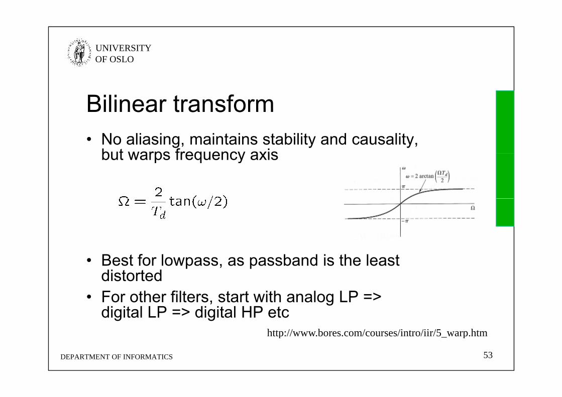
Bilinear transformBilinear transform• No aliasing, maintains stability and causality,
but warps frequency axisbut warps frequency axis
• Best for lowpass, as passband is the least distorted
• For other filters, start with analog LP => digital LP => digital HP etc
http://www bores com/courses/intro/iir/5 warp htm
DEPARTMENT OF INFORMATICS 53
http://www.bores.com/courses/intro/iir/5_warp.htm

UNIVERSITY OF OSLO
Matlab IIR Digital Filter DesignMatlab IIR Digital Filter DesignMatlab IIR Digital Filter DesignMatlab IIR Digital Filter Design• Order Estimation• For IIR filter design using bilinear transformation,
MATLAB statements to determine the order and bandedge are:[N, Wn] = buttord(Wp, Ws, Rp, Rs);
[N, Wn] = cheb1ord(Wp, Ws, Rp, Rs);
[N W ] h b2 d(W W R R )[N, Wn] = cheb2ord(Wp, Ws, Rp, Rs);
[N, Wn] = ellipord(Wp, Ws, Rp, Rs);
DEPARTMENT OF INFORMATICS 54

UNIVERSITY OF OSLO
Matlab IIR Digital Filter DesignMatlab IIR Digital Filter DesignMatlab IIR Digital Filter DesignMatlab IIR Digital Filter Design• Filter Design• For IIR filter design using bilinear transformation,
MATLAB statements to use are:[b, a] = butter(Nb, Wn), ,
[b, a] = cheby1(Nc, Rp, Wn)
[b, a] = cheby2(Nc, Rs, Wn)
[b, a] = ellip(Ne, Rp, Rs, Wn)
• No need to think about bilinear transform• Transfer function can be computed using freqz(b a w)• Transfer function can be computed using freqz(b, a, w)
where w is a set of angular frequencies
DEPARTMENT OF INFORMATICS 55

UNIVERSITY OF OSLO
Matlab IIR Digital Filter DesignMatlab IIR Digital Filter DesignMatlab IIR Digital Filter DesignMatlab IIR Digital Filter Design• Design an elliptic IIR lowpass filter with
F 0 8 kH F 1 kH F 4 kH 0 5Fp=0.8 kHz, Fs=1 kHz, Fsample=4 kHz, p = 0.5 dB, s=40 dB
• Code fragments used are:• Code fragments used are:[N,Wn] = ellipord(0.8/(4/2), 1/(4/2), 0.5, 40);
Result: N=5 order W =0 4– Result: N=5. order, Wn=0.4(compare with Nb=18, Nc=8)
[b a] = ellip(N 0 5 40 Wn);[b, a] = ellip(N, 0.5, 40, Wn);
• Full example: IIRdesign.m
DEPARTMENT OF INFORMATICS 56

UNIVERSITY OF OSLO
Matlab IIR Digital Filter DesignMatlab IIR Digital Filter DesignMatlab IIR Digital Filter DesignMatlab IIR Digital Filter Design
0
Elliptic IIR Lowpass Filter
-0 1
0Passband Details
-20
Gai
n, d
B
-0.3
-0.2
-0.1
Gai
n, d
B0 0.2 0.4 0.6 0.8 1
-60
-40G
0 0.1 0.2 0.3 0.4-0.5
-0.4
G0 0.2 0.4 0.6 0.8 1
/0 0.1 0.2 0.3 0.4
/
DEPARTMENT OF INFORMATICS 57

UNIVERSITY OF OSLO
9 8 Effekter av endelig ordlengde9.8 Effekter av endelig ordlengde• Koeffisienter blir avkortet
– Som regel blir det en liten endring av frekvensresponsSom regel blir det en liten endring av frekvensrespons– Katastrofal feil: en pol innenfor |z|=1 kan havne utenfor (bare
IIR)• Aritmetikken foregår med endelig presisjon
– Filteret blir et ikke-lineært system– Kvantiseringsstøy og avrundingsstøy– Feil pga overstyring
• Limit cycles: Oscillasjoner på utgangen uten inngang• Limit cycles: Oscillasjoner på utgangen uten inngang– Bare i IIR da det trenger tilbakekobling– Fullskala oscillasjoner hvis overstyring folder rundt
(x>xmax ⇒ –xmax) i stedet for metning (x>xmax ⇒ xmax)– Små oscillasjoner hvis avrunding istedet for avkorting– http://cnx.org/content/m11928/latest/
DEPARTMENT OF INFORMATICS 58


![FilterDesign and HFSS HO[1]](https://static.documents.pub/doc/80x56/54508235af795929148b4966/filterdesign-and-hfss-ho1.jpg)


![{Slides} Job+ Presentation Slides [MKS-40]](https://static.documents.pub/doc/80x56/58f058861a28ab96248b45f5/slides-job-presentation-slides-mks-40.jpg)