IJECT VOL. 6, ISSUE 3, JULY - SEPT 2015 www.iject.org INTERNATIONAL JOURNAL OF ELECTRONICS & COMMUNICATION TECHNOLOGY 9 ISSN : 2230-7109 (Online) | ISSN : 2230-9543 (Print) Kinematic Principle of Reflex Klystron: A Necessary Revisit 1 B.N. Biswas, 2 S. Chatterjee, 3 B. Choudhury, 4 S Guha Mallick 1,4 Sir J.C. Bose School of Engineering, SKF Group of Institutions, Hooghly, West Bengal, India 2 Kanailal Vidyamandir (Fr. Section), Chandernagore, Hooghly, West Bengal, India 3 Kalna College, Kalna, Burdwan, West Bengal, India Abstract Reflex Klystron (RK) is an oscillator. Like any other oscillators, it is expected that with the switching on the power supply, the oscillation should start building up either from an infinitesimally small value or from a finite value of small excitation. Thus RK can behave as either a soft-self-excited or a hard-self-excited oscillator- yet to be explored. Naturally it takes different finite durations to attain the steady state value in these two situations. Moreover, RK is not a continuous feedback oscillator but is a discrete time feedback oscillator and naturally the design of the resonator plays an important role. A new method is also adopted to calculate the spectral components of the output current waveform. Keywords Reflex Klystron Oscillator (RKO), Starting Current of RKO I. Introduction The 1939 was the epicenter of the golden period when principle of velocity modulation was evolved in order to overcome the transit time limitations of vacuum tubes. As a result, low power microwave oscillator called Reflex Oscillator, a trade mark of Sperry Gyroscope Company was developed where simple RLC resonator was also replaced by ‘rhumbatrons’ meaning rhythmic oscillation with a Q value of the order of 5-88.104. The Reflex Oscillator then found useful applications in double-detection receivers or as a frequency modulated oscillator in low power transmitters [1]. In the development of the theoretical basis of the Klystron operation, kinematics were used by the W C Hahn neglecting the space charge effects. Latter W C Hahn hinted how space charge effect can be taken into account to predict the tube behavior, On the other hand, latter Simon Ramo developed the theory of velocity modulation by incorporating displacement current and variations of fields charge and current densities with beam cross section, length and time by invoking Maxwell’s equations. He explained the principle of velocity modulation through the existence of two slow space charge waves – one of the waves propagates with a velocity slightly greater and the other slightly less than that of the beam current [2]. In fact this concept helped Webster to explain the phenomenon of de-bunching in Klystron. This creates difficulty in realizing the ideal efficiency. According to him de-bunching does not limit the number of bunches a beam may contain but limits length. But the author feels that the final conclusions more or less agree with the outcome of Kinematic principle of velocity modulation [3-10]. Reflex Klystron Oscillator (RKO) is a velocity modulated tube and is fairly an old topic. As such a large number of papers have been published on RKO. Notwithstanding these, some of the questions still remained unanswered. A schematic arrangement of an RKO is depicted in figure 1 along with the potential distribution (neglecting space charge distribution). Fig. 1: Schematic Diagram of RKO II. Positive Feedback in Reflex Klystron To explain the phenomena of oscillations in a Reflex Klystron, let us refer to an idealized configuration of the system as shown in fig. 1. The vital features of the reflex oscillators are, (1) the initial periodic wave generated when the klystron is switched on, (2) the formation of electron bunch and (3) appropriate time of return of the bunches so that they transfer energy to the resonator. The motion of electrons in the drift may be linked with the projectile motion in the gravitational field of the earth. Let us refer to the transient oscillatory voltage across the resonator grid. The electron at an instant of time ‘t 1 ’ with velocity ‘v 1 ’ is thrown into the retarding field at the drift space, another at ‘t 0 ’ with velocity ‘v 0 ’ and another at time ‘t 2 ’ with velocity ‘v 2 ’. By appropriately adjusting the repeller voltage ‘V R ’ and the accelerating voltage ‘V 0 ’, all the three electrons can be back to the resonator grid at the same time as indicated. This instant of falling back must be at the alternating voltage at the positive, thus forcing the bunch to transfer energy to the resonator. This is illustrated in the modified Applegate diagram of fig. 2.
Transcript
IJECT Vol. 6, IssuE 3, July - sEpT 2015
w w w . i j e c t . o r g InternatIonal Journal of electronIcs & communIcatIon technology 9
Kinematic Principle of Reflex Klystron: A Necessary Revisit1B.N. Biswas, 2S. Chatterjee, 3B. Choudhury, 4S Guha Mallick
1,4Sir J.C. Bose School of Engineering, SKF Group of Institutions, Hooghly, West Bengal, India2Kanailal Vidyamandir (Fr. Section), Chandernagore, Hooghly, West Bengal, India
3Kalna College, Kalna, Burdwan, West Bengal, India
Abstract Reflex Klystron (RK) is an oscillator. Like any other oscillators, it is expected that with the switching on the power supply, the oscillation should start building up either from an infinitesimally small value or from a finite value of small excitation. Thus RK can behave as either a soft-self-excited or a hard-self-excited oscillator- yet to be explored. Naturally it takes different finite durations to attain the steady state value in these two situations. Moreover, RK is not a continuous feedback oscillator but is a discrete time feedback oscillator and naturally the design of the resonator plays an important role. A new method is also adopted to calculate the spectral components of the output current waveform.
Keywords Reflex Klystron Oscillator (RKO), Starting Current of RKO
I. IntroductionThe 1939 was the epicenter of the golden period when principle of velocity modulation was evolved in order to overcome the transit time limitations of vacuum tubes. As a result, low power microwave oscillator called Reflex Oscillator, a trade mark of Sperry Gyroscope Company was developed where simple RLC resonator was also replaced by ‘rhumbatrons’ meaning rhythmic oscillation with a Q value of the order of 5-88.104. The Reflex Oscillator then found useful applications in double-detection receivers or as a frequency modulated oscillator in low power transmitters [1].
In the development of the theoretical basis of the Klystron operation, kinematics were used by the W C Hahn neglecting the space charge effects. Latter W C Hahn hinted how space charge effect can be taken into account to predict the tube behavior, On the other hand, latter Simon Ramo developed the theory of velocity modulation by incorporating displacement current and variations of fields charge and current densities with beam cross section, length and time by invoking Maxwell’s equations. He explained the principle of velocity modulation through the existence of two slow space charge waves – one of the waves propagates with a velocity slightly greater and the other slightly less than that of the beam current [2]. In fact this concept helped Webster to explain the phenomenon of de-bunching in Klystron. This creates difficulty in realizing the ideal efficiency. According to him de-bunching does not limit the number of bunches a beam may contain but limits length. But the author feels that the final conclusions more or less agree with the outcome of Kinematic principle of velocity modulation [3-10].
Reflex Klystron Oscillator (RKO) is a velocity modulated tube and is fairly an old topic. As such a large number of papers have been published on RKO. Notwithstanding these, some of the questions still remained unanswered. A schematic arrangement of an RKO is depicted in figure 1 along with the potential distribution (neglecting space charge distribution).
Fig. 1: Schematic Diagram of RKO
II. Positive Feedback in Reflex KlystronTo explain the phenomena of oscillations in a Reflex Klystron, let us refer to an idealized configuration of the system as shown in fig. 1. The vital features of the reflex oscillators are, (1) the initial periodic wave generated when the klystron is switched on, (2) the formation of electron bunch and (3) appropriate time of return of the bunches so that they transfer energy to the resonator. The motion of electrons in the drift may be linked with the projectile motion in the gravitational field of the earth. Let us refer to the transient oscillatory voltage across the resonator grid. The electron at an instant of time ‘t1’ with velocity ‘v1’ is thrown into the retarding field at the drift space, another at ‘t0’ with velocity ‘v0’ and another at time ‘t2’ with velocity ‘v2’. By appropriately adjusting the repeller voltage ‘VR’ and the accelerating voltage ‘V0’, all the three electrons can be back to the resonator grid at the same time as indicated. This instant of falling back must be at the alternating voltage at the positive, thus forcing the bunch to transfer energy to the resonator. This is illustrated in the modified Applegate diagram of fig. 2.
w w w . i j e c t . o r g 10 InternatIonal Journal of electronIcs & communIcatIon technology
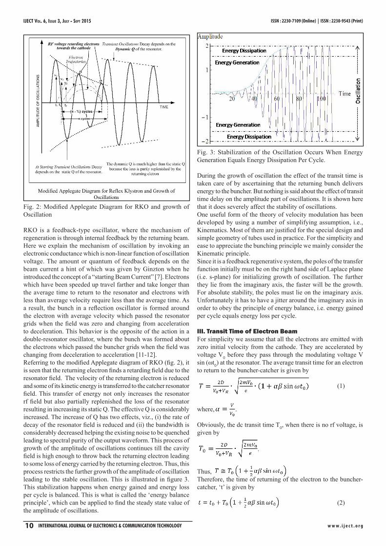
Fig. 2: Modified Applegate Diagram for RKO and growth of Oscillation
RKO is a feedback-type oscillator, where the mechanism of regeneration is through internal feedback by the returning beam. Here we explain the mechanism of oscillation by invoking an electronic conductance which is non-linear function of oscillation voltage. The amount or quantum of feedback depends on the beam current a hint of which was given by Ginzton when he introduced the concept of a “starting Beam Current” [7]. Electrons which have been speeded up travel farther and take longer than the average time to return to the resonator and electrons with less than average velocity require less than the average time. As a result, the bunch in a reflection oscillator is formed around the electron with average velocity which passed the resonator grids when the field was zero and changing from acceleration to deceleration. This behavior is the opposite of the action in a double-resonator oscillator, where the bunch was formed about the electrons which passed the buncher grids when the field was changing from deceleration to acceleration [11-12].Referring to the modified Applegate diagram of RKO (fig. 2), it is seen that the returning electron finds a retarding field due to the resonator field. The velocity of the returning electron is reduced and some of its kinetic energy is transferred to the catcher resonator field. This transfer of energy not only increases the resonator rf field but also partially replenished the loss of the resonator resulting in increasing its static Q. The effective Q is considerably increased. The increase of Q has two effects, viz., (i) the rate of decay of the resonator field is reduced and (ii) the bandwidth is considerably decreased helping the existing noise to be quenched leading to spectral purity of the output waveform. This process of growth of the amplitude of oscillations continues till the cavity field is high enough to throw back the returning electron leading to some loss of energy carried by the returning electron. Thus, this process restricts the further growth of the amplitude of oscillation leading to the stable oscillation. This is illustrated in figure 3. This stabilization happens when energy gained and energy loss per cycle is balanced. This is what is called the ‘energy balance principle’, which can be applied to find the steady state value of the amplitude of oscillations.
Fig. 3: Stabilization of the Oscillation Occurs When Energy Generation Equals Energy Dissipation Per Cycle.
During the growth of oscillation the effect of the transit time is taken care of by ascertaining that the returning bunch delivers energy to the buncher. But nothing is said about the effect of transit time delay on the amplitude part of oscillations. It is shown here that it does severely affect the stability of oscillations.One useful form of the theory of velocity modulation has been developed by using a number of simplifying assumption, i.e., Kinematics. Most of them are justified for the special design and simple geometry of tubes used in practice. For the simplicity and ease to appreciate the bunching principle we mainly consider the Kinematic principle.Since it is a feedback regenerative system, the poles of the transfer function initially must be on the right hand side of Laplace plane (i.e. s-plane) for initializing growth of oscillation. The further they lie from the imaginary axis, the faster will be the growth. For absolute stability, the poles must lie on the imaginary axis. Unfortunately it has to have a jitter around the imaginary axis in order to obey the principle of energy balance, i.e. energy gained per cycle equals energy loss per cycle.
III. Transit Time of Electron BeamFor simplicity we assume that all the electrons are emitted with zero initial velocity from the cathode. They are accelerated by voltage V0 before they pass through the modulating voltage V sin (ωt0) at the resonator. The average transit time for an electron to return to the buncher-catcher is given by
(1)
where, . Obviously, the dc transit time T0, when there is no rf voltage, is given by
Thus, Therefore, the time of returning of the electron to the buncher-catcher, ‘t’ is given by
(2)
IJECT Vol. 6, IssuE 3, July - sEpT 2015
w w w . i j e c t . o r g InternatIonal Journal of electronIcs & communIcatIon technology 11
A. Output Current – A New ApproachLet a bunch of electrons during a small interval of time “dt0” corresponding to current I0 enter from the buncher to the drift space. The electrons, following a parabolic path, return to the grid of buncher within a time interval “dt”. Here “T” is the transit time. Obviously, “t”, the time of return is given by “t = t0+T”. Hence
0 0
1dt dTdt dt
= +
Again by the conservation of charge
One finds that
where ψ = ωT0. Thus we get
Since generation of oscillation is based on the synchronous supply of energy by the returning electron-bunches to the buncher, the generated waveform is inherently rich in harmonics. As such the fundamental component of the wave is calculated by Fourier analysis. But in this paper a novel method, which is simple and accurate, is used to calculate the fundamental component. It can be shown that the fundamental component of current returning to the buncher grid is
(3)
where, putting Y = X J0 (X) for convenience
201
1)(Y
YF−
=
2
2
111)(
YYYYF
−
−−= (4)
Note that there will be a phase reversal of 1800 degree of the beam current and as a result the fundamental component of current induced to the resonator is
(5)The results are verified through FFT calculation of the actual waveform. This is shown in fig. 4 showing remarkable agreement.
Fig. 4: Theoretical and empirical results compared with FFT values as a function of modulation index X.
B. Electronic AdmittanceIt is usually convenient to express the transit time in terms of the number of oscillation cycles N. That is,
Hence,
(6)
Fig. 5: Applegate Diagram of RKO
Referring to Applegate diagram in fig. 5, it is seen that the bunch centre is formed at the peak of the fundamental component of current about the electron which leaves the resonator gap at the instant which is at a quarter of a cycle after the peak of the rf gap voltage. Thus taking this into consideration one writes the resonator voltage in relation to fundamental component of current as
(7)Referring to the fundamental component of the induced currents one writes for the beam admittance
Or,
(8)Again remembering that
(9)where the electronic conductance and susceptance is given by
(10)
C. Starting Current of Oscillation in RKOFig. 4 shows the dependence of fundamental component of current on the parameter X. Taking consideration of the phase relation the beam current (ib) injected into the resonator will be negative. Thus we can write that
w w w . i j e c t . o r g 12 InternatIonal Journal of electronIcs & communIcatIon technology
3 5
01.0 0.782 0.353bi X X X
I= − − +
Remembering that X= 1/2αβψ and ψ=2πN, we find that Therefore, electronic conductance is given by
For permitted values of sinψ, Ge becomes negative
Weak oscillation corresponds to very small value of V and hence X.
Fig. 6: Beam Conductance and Cavity Load
The condition of starting oscillation is that the resonator loss along with the load will be balanced by the electronic conductance, as shown in fig. 6. Thus the starting current of oscillation (Ios ) can be found as follows,
Therefore, the value of the ‘starting current’ is given by
(11)
Note that higher the value of N, lower is the value of the starting current. Some idea of the value of starting current for oscillation can be had by assuming
D. Pole Movement in RKOA sinusoidal oscillator can start to producing sinusoidal output when the poles of the circuit remain in the right half plane and for stable oscillation there must be a mechanism that helps the poles to move in right half plane [1-5]. On the other hand in an electronic or opto-electronic oscillator [6-10] with an embedded RLC circuit, the poles are forcibly placed on the right half plane and as far as practicable away from the imaginary axis in order to help growth of oscillation as quickly as possible. And ultimately it is imagined that the poles are almost frozen on the imaginary axis. But for an ideal linear harmonic oscillator the poles are really frozen so that the oscillation neither grows nor decays.
But all the earlier papers on reflex klystrons are silent about the pole movement.Since RK is an oscillating system its poles, to begin with, must lie on the right half of the s-plane as far as possible for rapid growth of oscillation and the poles must move towards the imaginary axis. The question is: does it remain on the imaginary axis? For absolute stability, the poles must lie on the imaginary axis. Unfortunately it has to have a jitter around the imaginary axis in order to obey the principle of energy balance, i.e. energy gained per cycle equals energy loss per cycle. The movements of the poles are expected to be different for soft-self and hard-self modes of oscillation. Incidentally it must be remembered that concept of poles and zeros of a system is valid for a linear system. Since an oscillator is a nonlinear circuit, we have got to equivalently linearize the system by invoking the describing function technique.
Fig. 7: Equivalent Circuit of a Reflex Klystron.
An equivalent circuit of a reflex klystron is shown in fig. 7. The circuit equation is written as (noting that is the voltage across the tuned circuit)
1 ( ) 0dvGv C vdt I vdt L
+ + + =∫3 5
1 0 2 0 3 0( ) ( )I v a I v a I v a I v= − − +
( )2
3 51 0 2 0 3 02 ( ) v 0d v d va I G a I v a I v
dt dt LC− − + − + = (12)
Poles and zeros are concepts which are valid for linear circuits. For example, for a parallel RLC circuit, the damping factor σ isknown to be given by . However, it can be applied to a nonlinear RLC circuit, by invoking the principle of equivalent linearization or describing function technique in which case, the damping constant can be expressed as , where V is the instantaneous amplitude of a sinusoidal voltage, say, V sinωt. Here referring nonlinear electronic conductance,
(13)
If G is the conductance of the tank of circuit, then the total Geq=(Ge- G) is written as,
IJECT Vol. 6, IssuE 3, July - sEpT 2015
w w w . i j e c t . o r g InternatIonal Journal of electronIcs & communIcatIon technology 13
where α1, α2 and α3 are constants of the non-linear element. Equation (12) turns out to be
( )2
2 (G )V 0ed V d VGdt dt LC
− − + =
Thus it is evident or apparent that as V grows Geq (V) tends to zero in the steady state. Putting,
We get,
Considering, v(t)=V(t) ejωt, it is easily seen that,
Fig. 8: Pole Movement in a Reflex Klystron
Naturally the poles move towards the imaginary axis from the right half of the s-or Laplace plane. Obviously in moving it will intrude into the left half of the s-plane. As soon as it happens, the amplitude will start decaying because of loss of energy and again it will cross to the right half plane and so it will grow again because of energy gain. This process will stabilize ultimately because of the principle of energy balance when the loss per cycle equals the energy gain per cycle.
E. Amplitude of Oscillation from the ‘principle of Energy Balance’The principle of conservation of energy states that the amount of energy supplied to a system during any time interval (t-t0) should be equal to the sum of the energy consumed in the system during the same time interval plus the increase of the energy stored in the system. Calling Pt the instantaneous power supplied to the system, Pc the power consumed and E0, Ethe initial and final energy stored, the energy equation will be given by:
Differentiation gives
In the steady state when the oscillator generates periodic waveform (say, with a period T) then
0 0
T T
t cPdt P dt=∫ ∫
Therefore
0
0T dE dt
dt=∫
Now the total energy stored in a complete cycle is written as
2 21 12 2LE Li Cv= +
So
( )LL L C
didE dvL i Cv v i idt dt dt
= + = + 3 5
1 0 2 0 3 0[( ) ]C Li i a I G v a I v a I v+ = − + −
3 51 0 2 0 3 0( ) )dE a I G v a I v a I v v
dt = − + −
Now for a complete cycle
23 5
1 0 2 0 3 00
( ) ) 0a I G v a I v a I v vdtp
− + − = ∫
Assuming the output of the oscillator of the form
we can write
2 42 0 3 01 0
3 5( ) 04 8osc osc
a I a Ia I G V V− + − =
4 23 21 0
5 3 ( / ) 08 4osc osca aV V a G I− − − =
When,
Then
2 20 2
3
32 25aV Ca
= =
It is to be remembered that for a soft-self-excited oscillator it is necessary that C1 > 0.
w w w . i j e c t . o r g 14 InternatIonal Journal of electronIcs & communIcatIon technology
Therefore,
12
222 8CCCx ++=
And the output power is given by
20
12 oscP V G=
The oscillator amplitude and power output has been depicted in the fig. 9.
Fig. 9: Oscillator Amplitude and Power Output
Referring the electrical equivalent model (fig. 7), we can write, (15)
Normalizing the time by ω0 t = τ, we get,
Where .
Therefore, β1= 0.2076√N. Typically, α1 = 1.0, α2=0.782, α3= 0.353, V0= 300 and β=1. So we can write the above equation as follows,
(16)
Where
Fig. 10 shows the solution in phase space, i.e., in plane. The phase space trajectory shows the growth of oscillation and the limit cycle of this periodic, non-linear system.
Fig. 10: Phase space plot of RKO, where .
F. Hard-Self and Soft-Self Excitation of RKOThe governing equation of the Reflex Klystron is
There can be three cases of interest, as given below, Case-I: when is positive:Here it is easily seen the oscillation will build up from an infinitesimal value for and will stabilize and show a limit cycle operation. Case-II: when C1 =0:Here again the oscillation will build up from an infinitesimal small value but will take a longer time to stabilize compared to Case I. It will also exhibit a limit cycle operation. Case-I and case-II are called ‘soft mode of self-excitation’.Case-III: When is negativeHere the oscillation can build up with an initial value of such that it satisfies the condition,- C1+β1 x
2 - x4 > 0 This is known as the ‘hard mode of self excitation’. Now consider that with the system as described by the equation, the system execute oscillation of the formv = V(t) cos (ψ(t)) (17)Then it can be easily shown,
(18)
Steady state value x0 are given by
(19)Which are obtained from
Stability of the solution is obtained by considering an infinitesimal deviation from stable amplitude (x0+ξ). Substituting x0=(x0+ξ) and retaining only first order terms in ξ we get,
(20)
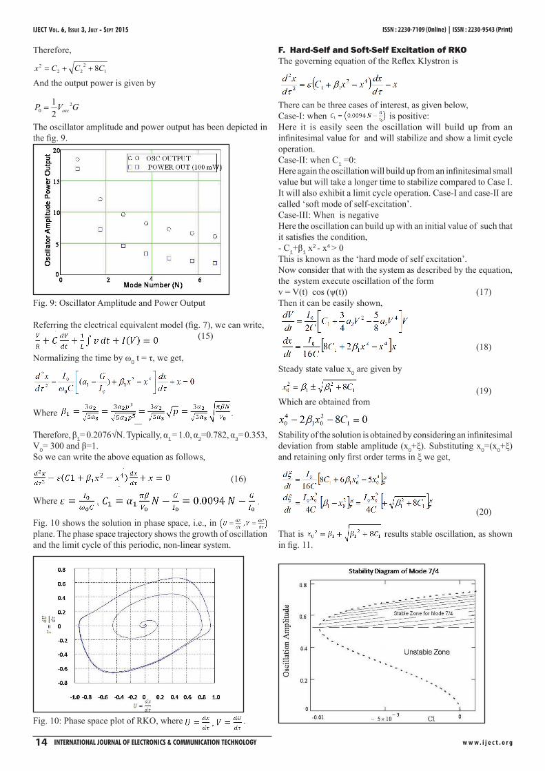
That is results stable oscillation, as shown in fig. 11.
IJECT Vol. 6, IssuE 3, July - sEpT 2015
w w w . i j e c t . o r g InternatIonal Journal of electronIcs & communIcatIon technology 15
Fig. 11: Amplitude of Oscillation as a function of conductance
.
Fig. 12: Oscillation amplitude as a function of, C1, i.e., G/I0.
Fig. 13: Transient Response, output amplitude (y) and dy/dt.
G. Effect of DelayWhen the transit time delay is taken into account, the normalized amplitude equation can be expressed as
Note that tr is the normalized transit time. It is further to be noted that it depends on N i.e. (n-1/4) when n runs through 1,2,3 etc. tr = N/f, let f = 10 GHz (Operating frequency), the tr=(n-1/4).1/f = (n-1/4) 10-10 an I/C = I/(C.10-9), t = t.10-9, then
Typical value of that transit time, and
IV. Jump Phenomenon in RKOAs explained earlier, the reflex oscillator can have both soft self-excitation and hard-self excitation depending upon the mode number '' N and ratio of 0/ IG (equivalent conductance of the timed circuit ''G and the dc beam current '' 0I ). The zone of stability for the mode 19/4 is shown in the fig. 14. It is very interesting to observe from the diagram that there is a possibility that at any particular value of 0/ IG , there can be two values of the oscillations amplitudes, both fall in the stable zone of operation. However, for lower value of the oscillation-amplitude the equivalent '' eQ is lower than that for the higher value of the amplitude of oscillations. This means that the lower amplitude of oscillation is more stable and that the higher amplitude of oscillation. To illustrate this let us consider the particular value of 0/ IG , the oscillator voltage takes that of ‘a’. If gradually decrease 0/ IG , the point will up to ‘b’. After that if we further try to decrease 0/ IG , the point will jump to ‘c’. After this if we further decrees the path will be from c to d. This illustrates Jump Phenomena in reflex oscillator (fig. 14).
Fig. 14: Hysteresis and Jump Phenomena in Reflex Klystron
V. Stationary Oscillation and Its StabilityLet us now consider the stability of the system when the oscillation has reached its steady state value. Incidentally, the stability of an oscillator means both the amplitude and the frequency stability of the oscillation. The technique of finding the stability of the stationary solution consists in seeking the solution of the amplitude and phase equations when small charges are given in the stationery
w w w . i j e c t . o r g 16 InternatIonal Journal of electronIcs & communIcatIon technology
state of oscillation. When the system is disturbed momentarily from its stable state, let the amplitude and the phase of the oscillation assume x0 + δx and θ0+δθ respectively. Once this happens the subsequent behavior of the oscillation will be completely governed by their respective amplitude and phase equations from which it is easy to find the equations for ∆x and ∆θ. ThusLet us assume that an increase of I0 is reflected by a change of oscillator amplitude ∆x. To examine whether ∆x and ∆θ dies out with time. Let us write their incremental equations
Remembering that x02 is given by
The above equation for ∆x turns out
We have already seen that the zone of stability is defined by the condition x0
2 > β1.Therefore ∆x will die out with time. Now, noting that an increase of I0 indicates an increase of V0. When V0 increases then transit time is also increase more than the mode centre value. As a result the frequency of oscillation will be less than the mode centre ω0. Therefore,
Where (ω1 - ω0) is denoted by -Δω. This clearly indicates stability of the frequency of oscillation.
VI. Modified Reflex KlystronFollowing the idea of Bakker and Vries (cf. “Amplification of Small Alternating Tensions by an Inductive Action of the Electrons in a Radio Valve” C. J. Bakker and G. De Vries entitled “Amplification of Small Alternating Tensions by an Inductive Action of the Electrons in a Radio Valve” Physica, 1934) of realizing amplification by inductive of the electrons from the anode of a tetrode valve we may configure the reflector in the form of a resonator as shown in the adjoining figure to realize amplification. Following their analytical method it can be sown that the output voltage as
It is interesting note that the output is proportional to frequency. It means the there is a possibility of FM to AM conversion it the reflex klystron is synchronized by an FM signal.
Fig. 15: Modified Reflex Klystron
VII. DiscussionIt is interesting to note that when the bunches are returning they induce an ac voltage on the repeller. This is concluded from a paper by C. J. Bakker and G. De Vries entitled “Amplification of Small Alternating Tensions by an Inductive Action of the Electrons in a Radio Valve”. The possibility of amplification is investigated both theoretically and experimentally when the anode is kept negative, so that the electrons in a thermionic valve cannot reach this anode, but approach it sufficiently near to induce considerable charges. The influence of the transit time is taken into account. The agreement of theory experiment is satisfactory.
VIII. AcknowledgmentThe authors are grateful to the Chairman Mr B Guha Mallick of Supreme Knowledge Foundation Group of Institutions (SKFGI) for providing all possible assistance in carrying the work. The authors are also thankful to Dr Malay Kanti Dey, Scientist F, VECC, Atomic Energy Commission , Govt of India for his assistance and advice.
Proceedings of the I.R.E., February, 1939, pp. 106-116.[2] Simon Ramo,“The Electronic-Wave Theory of Velocity-
Modulation Tubes”, Proceedings of the I.R.E., December,1939, pp. 757-763.
[3] Karl G. Jansky,“An Experimental Investigation of the Characteristics of Certain Types of Noise”, Proceedings of the I.R.E., December, 1939, pp. 763.
[4] A. E. Harrison,“Kinematics of Reflection Oscillators”, Journal of Applied Physics 15, 709, pp. 709-711, 1944.
[5] Russell H. Varian, Stgurd F. Varian,“A High Frequency Oscillator and Amplifier”, Vol. 10, May, pp. 321-327, 1939.
[6] Edward Leonard Ginzton, Arthur E. Harrison,“Reflex-Klystron Oscillators”, Proceedings of the I.R.E. and Waves and Electrons, 1946, pp. 97-113.
[7] J. R. Pierce,“Reflex Oscillators”, Proceedings of the I.R.E., February, 1945, pp. 112-118.
[8] Edward N. Dingley,“The Theory of Transmission Lines”, Proceedings of the I.R.E., February, pp. 118, 1945.
[9] J.R. Pierce,“Reflex Oscillators”, Proceedings of the I.R.E., July, 1945, pp. 483-485.
[10] David L. Webster,“Cathode-Ray Bunching”, Vol. 10, July, 1939, pp. 501-508.
[11] David L. Webster,“Velocity-Modulation Currents", Journal of Applied Physics, pp. 786-787.
[12] David L. Webster,“The Theory of Klystron Oscillations”, Journal of Applied Physics, pp. 864-872.