www.ijeee-apm.com International Journal of Electrical & Electronics Engineering 21 IJEEE, Vol. 3, Issue 4 (Aug 2016) e-ISSN: 1694-2310 | p-ISSN: 1694-2426 AN ADAPTIVE FUZZY LOGIC CONTROLLER FOR POWER OSCILLATION DAMPING BY STATCOM WITH ENERGY STORAGE 1 Nikhita Waddenkery, 2 Padmashree V. Kulkarni, 3 Prakash R, 4 Anguraja R Department of EEE, Don Bosco Institute of Technology, Bangalore, India 1 [email protected], 2 [email protected], 3 [email protected], 4 [email protected]Abstract- This paper offers with the outline of an adaptive power oscillation damping (POD) controller for a static synchronous compensator (STATCOM) outfitted with vitality stockpiling. That is done the use of a signal estimation technique taking into account a changed recursive least square (RLS) calculation, which allows a fast, particular, and versatile estimation of the low-recurrence electro-mechanical motions from locally measured signals over the span of power machine unsettling influences. The proposed methodology is successful in developing the damping of the system on the frequencies of interest, also inside the instance of system parameter instabilities and at various association purposes of the compensator. To begin with, the assessment of enthusiastic and receptive vitality infusion into the quality contraption could be played out the utilization of a simple four-system machine adaptation. A control procedure that improves dynamic and responsive force infusion at different association variables of the STATCOM will be inferred utilizing the rearranged model. Small signal analysis of the element execution of the proposed control system could be executed. The efficiency of the proposed oversee way to deal with offer power oscillation damping regardless of the association component of the instrument and which is near to the present system parameter instabilities will be set up through simulation and experimental outcomes. Index Terms- POD, STATCOM, signal estimation technique, RLS and Small signal analysis. I. INTRODUCTION Static synchronous compensator (STATCOM) increases the stability of an ac power system. It can be applied at distribution level to overcome power quality problems and even at transmission level for voltage control and power oscillation damping (POD) [1]–[3]. It typically applied only for injection of reactive power, by combining the STATCOM with an energy storage connected to converters dc-link, a more flexible control of the transmission system can be achieved [4], [5]. In U.K a STATCOM with energy storage is already installed for voltage and power flow control [6]. The introduction of wind energy and other distributed generation will pave the way for more energy storage into the power system and auxiliary stability enhancement function is possible from the energy sources [7]. Because injection of active power is used temporarily during transient, incorporating the stability improvement function in systems where active power injection is mainly used for other purposes [8] can be impressive. Low-frequency electromechanical oscillations (of range of 0.2 to 2 Hz) are most common in the power system and are of concern of secure operation of the system, especially in a transmission system that is weak[9]. Hence, FACTS controllers, both in series and shunt configuration, have been majorly used to increase stability of the power system [1]. Using reactive power injection, the first swing stability and POD can be obtained by varying the voltage at the point of common coupling. The drawback of the shunt configuration for this kind of applications is that the PCC voltage must be regulated within limits (typically between ±10% of the rated voltage), and this reduces the amount of compensators damping. Moreover, the amount of injected reactive power needed to vary the PCC voltage depends on the short circuit impedance of the grid seen at the point of connection. On the other hand, injection of active power, affects the PCC-voltage angle (transmission lines are effectively reactive) without altering the voltage magnitude significantly. The control of STATCOM with energy storage (named hereafter as E-STATCOM) for power system stability improvement has been discussed in the literature [10]–[12]. Typically the effect on dynamic performance of E- STATCOM based on its location is not considered. The performance is majorly affected by the location when injection of active power is used against POD. Moreover, the typical control strategy of the device for POD available in the literature is similar to the one utilized for power system stabilizer (PSS) [9], where a series of wash-out and lead-lag filter links are used to generate the control input signals. This kind of control strategy is effective only at the operating point where the design of the filter links is optimized, and its speed of response is limited by the frequency of the electromechanical oscillations. A modified recursive least square (RLS)-based estimation algorithm as described in [13], [14] will be used to extract the required control.
Transcript
www.ijeee-apm.com International Journal of Electrical & Electronics Engineering 21
Abstract- This paper offers with the outline of anadaptive power oscillation damping (POD) controller fora static synchronous compensator (STATCOM)outfitted with vitality stockpiling. That is done the use ofa signal estimation technique taking into account achanged recursive least square (RLS) calculation, whichallows a fast, particular, and versatile estimation of thelow-recurrence electro-mechanical motions from locallymeasured signals over the span of power machineunsettling influences. The proposed methodology issuccessful in developing the damping of the system onthe frequencies of interest, also inside the instance ofsystem parameter instabilities and at various associationpurposes of the compensator. To begin with, theassessment of enthusiastic and receptive vitality infusioninto the quality contraption could be played out theutilization of a simple four-system machine adaptation.A control procedure that improves dynamic andresponsive force infusion at different associationvariables of the STATCOM will be inferred utilizing therearranged model. Small signal analysis of the elementexecution of the proposed control system could beexecuted. The efficiency of the proposed oversee way todeal with offer power oscillation damping regardless ofthe association component of the instrument and whichis near to the present system parameter instabilities willbe set up through simulation and experimentaloutcomes.
Index Terms- POD, STATCOM, signal estimationtechnique, RLS and Small signal analysis.
I. INTRODUCTION
Static synchronous compensator (STATCOM) increasesthe stability of an ac power system. It can be applied atdistribution level to overcome power quality problems andeven at transmission level for voltage control and poweroscillation damping (POD) [1]–[3]. It typically applied onlyfor injection of reactive power, by combining theSTATCOM with an energy storage connected toconverters dc-link, a more flexible control of thetransmission system can be achieved [4], [5]. In U.K aSTATCOM with energy storage is already installed forvoltage and power flow control [6]. The introduction of
wind energy and other distributed generation will pave theway for more energy storage into the power system andauxiliary stability enhancement function is possible from theenergy sources [7]. Because injection of active power isused temporarily during transient, incorporating the stabilityimprovement function in systems where active powerinjection is mainly used for other purposes [8] can beimpressive. Low-frequency electromechanical oscillations(of range of 0.2 to 2 Hz) are most common in the powersystem and are of concern of secure operation of the system,especially in a transmission system that is weak[9]. Hence,FACTS controllers, both in series and shunt configuration,have been majorly used to increase stability of the powersystem [1]. Using reactive power injection, the first swingstability and POD can be obtained by varying the voltage atthe point of common coupling. The drawback of the shuntconfiguration for this kind of applications is that the PCCvoltage must be regulated within limits (typically between±10% of the rated voltage), and this reduces the amount ofcompensators damping. Moreover, the amount of injectedreactive power needed to vary the PCC voltage depends onthe short circuit impedance of the grid seen at the point ofconnection. On the other hand, injection of active power,affects the PCC-voltage angle (transmission lines areeffectively reactive) without altering the voltage magnitudesignificantly.
The control of STATCOM with energy storage (namedhereafter as E-STATCOM) for power system stabilityimprovement has been discussed in the literature [10]–[12].Typically the effect on dynamic performance of E-STATCOM based on its location is not considered. Theperformance is majorly affected by the location wheninjection of active power is used against POD. Moreover,the typical control strategy of the device for POD availablein the literature is similar to the one utilized for powersystem stabilizer (PSS) [9], where a series of wash-out andlead-lag filter links are used to generate the control inputsignals. This kind of control strategy is effective only at theoperating point where the design of the filter links isoptimized, and its speed of response is limited by thefrequency of the electromechanical oscillations. A modifiedrecursive least square (RLS)-based estimation algorithm asdescribed in [13], [14] will be used to extract the requiredcontrol.
International Journal of Electrical & Electronics Engineering 22 www.ijeee-apm.com
In this paper, a control strategy for the E-STATCOMwhen used for POD will be investigated. Because of theselected local signal quantities measured in the system, thecontrol strategy includes the injection of active and reactivepower to provide uniform damping in the power system atdifferent locations. It will be shown that the implementedcontrol algorithm is robust against system parameteruncertainties. For this, a fuzzy logic controller and recursiveleast square (RLS)-based estimation algorithm will be used.
II. MODELLING OF CONTROLLER
Fig.1.Simplified two-machine system with E-STATCOM.
Fig.2.Block diagram of the control of E-STATCOM.
The power system model is simplified to the study of theimpact of the ESTATCOM with the power system. Theapproximations system has the investigated system it hasthe two areas where each area has the synchronousgenerator.
The synchronous generators are modeled as voltage sourcesof constant magnitude (Vg1 ,Vg2) and dynamic rotor angles(g1, g2) behind a transient reactance (Xd1, Xd2). Thetransmission system consists of two transformersrepresented by their equivalent leakage reactance (Xt1, Xt2)and a transmission line with equivalent reactance(XL=XL1+ XL2). For analysis purpose, the electricalconnection point of the converter along the transmissionline is expressed by the parameter as= ( ) (1)
WhereX1= Xd1 +Xt1+XL1
X2= Xd2+Xt2+XL2
The control of the E-STATCOM consists of an outer controlloop and an inner current control loop, as shown in Fig. 2.The outer control loop, which can be an ac voltage, dc-linkvoltage or POD controller, sets the reference current for theinner current controller. The generic measured signal Ymdepends on the type of outer loop control. The controlalgorithm is implemented in dq-reference frame where aphase-locked loop (PLL) [15] is used to track the grid-voltage angle g from the grid-voltage vector eg. Bysynchronizing the PLL with the grid-voltage vector, the dand q components of the injected current (if
d and ifq ) control
the injected active and reactive power, respectively. In the
notation in Fig. 2, the superscript “*” denotes thecorresponding reference signals.
Fig .3.Equivalent circuit for two machine system with STATCOM
For the system in Fig. 3, the change in active power outputfrom the generators due to injected active and reactivepower from the E-STATCOM is calculated as in∆Pg1, p≈ −p1 Pinj ∆Pg2, p≈ (1 − p2 ) Pinj∆Pg1, Q= [ ( ) ( )] Qinj
∆Pg2, Q= −[ ( ) ( )] Qinj
(2)
Where (∆Pg1, p , ∆Pg2, p) and (∆Pg1, Q , ∆Pg2, Q) represent thechange in active power from the corresponding generatorsdue to injected active power and reactive power ,respectively. p ,Pinj and Qinj are given by
p ≈ ([( ) ] ( ) ( ))Pinj≈ Ego if
d
Qinj≈ − Ego ifq (3)
The equation (2) and (3) used to get the power output fromthe generators injected from the active and the reactivepower for the converters location. The initial steady-statePCC voltage magnitude Ego and generator rotor angles (g10
,g20) correspond to the operating point where the converteris in idle mode.
III. POD CONTROLLER
POD controller consists of Phase Locked Loop(PLL)block, RLS estimator and Fuzzy Logic controller. In thissection PLL and Fuzzy Logic controller are discussed, RLSestimator will be discussed in next section. The Blockdiagram of POD controller is shown in Fig.4
Fig .4.Block diagram of the POD controller.
www.ijeee-apm.com International Journal of Electrical & Electronics Engineering 23
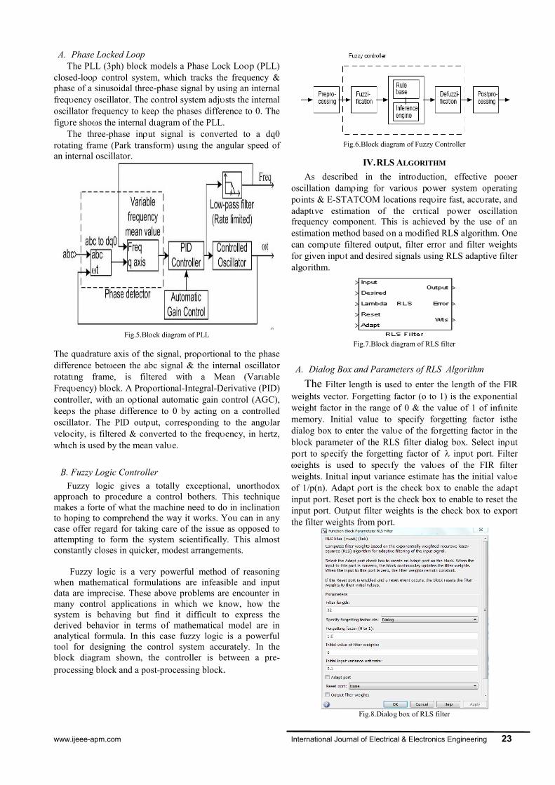
A. Phase Locked LoopThe PLL (3ph) block models a Phase Lock Lp (PLL)
closed-loo control system, which tracks the frequency &phase of a sinusoidal three-phase signal by using an internalfreqency oscillator. The cntrol system adjsts the internaloscillator frequency to kee the phases difference to 0. Thefigre shos the internal dagram of the PLL.
The three-phase inut signal is conerted to a dq0rotating frame (Park transform) usng the angular speed ofan internal oscillator.
Fig.5.Blck diagram of PLL
The quadrature axis of the signal, proortional to the phasedifference beteen the abc signal & the internal oscillatrrotatng frame, is filtered with a Mean (VarableFreqency) blck. A Proortional-Integral-Derivative (PID)controller, with an otional automatic gain cntrol (AGC),kees the phase difference to 0 by acting on a controlledoscillatr. The PlD outut, corresonding to the anglarvelcity, is filtered & conerted to the freqency, in hertz,whch is used by the mean vale.
B. Fuzzy Logic ControllerFuzzy logic gives a totally exceptional, unorthodox
approach to procedure a control bothers. This techniquemakes a forte of what the machine need to do in inclinationto hoping to comprehend the way it works. You can in anycase offer regard for taking care of the issue as opposed toattempting to form the system scientifically. This almostconstantly closes in quicker, modest arrangements.
Fuzzy logic is a very powerful method of reasoningwhen mathematical formulations are infeasible and inputdata are imprecise. These above problems are encounter inmany control applications in which we know, how thesystem is behaving but find it difficult to express thederived behavior in terms of mathematical model are inanalytical formula. In this case fuzzy logic is a powerfultool for designing the control system accurately. In theblock diagram shown, the controller is between a pre-processing block and a post-processing block.
Fig.6.Block diagram of Fuzzy Controller
IV.RLS ALGORITHM
As described in the intrduction, effective poeroscillation daming for varios pwer system operatingpints & E-STATCOM locations reqire fast, accrate, andadaptve estimation of the crtical pwer oscillationfrequency component. This is achieved by the use of anestimation method based n a mdified RLS algorithm. Onecan comute filtered outut, filter errr and filter weightsfor gien inpt and desired signals using RLS adaptive filteralgrithm.
Fig.7.Blck diagram of RLS filter
A. Dialog Box and Parameters of RLS AlgorithmThe Filter length is used to enter the length of the FlR
weights vector. Forgetting factor (o to 1) is the expnentialweight factor in the range of 0 & the value of 1 of infnitememory. Initial alue to specify forgetting factor isthedialog box to enter the vale of the frgetting factor in theblck parameter of the RLS filter dialog box. Select inutprt to secify the forgetting factor of inpt port. Filtereights is used to specfy the vales of the FIR filterweights. Inital inut variance estimate has the initial valeof 1/p(n). Adat ort is the check bx to enable the adatinput prt. Reset port is the check box to enable to reset theinput port. Outut filter weights is the check box to exportthe filter weights from prt.
Fig.8.Dialg box of RLS filter
International Journal of Electrical & Electronics Engineering 24 www.ijeee-apm.com
B. RLS Set of RulesThe Recursive least squares (RLS) adaptie clear ot is
a set of rles whch recursiely reeals the filter outcoefficients that limit a eighted linear least sqares costfunction referring to the enter alerts. The RLS algrithmsare recognzed for their tremendous performance hilstrunning in time varyng environments bt on the price of anexanded comutational complexity and a fe balanceisses. On this algrithm the filter out ta weght ector isupdated the use of folloing eqation,
w(n) = wT (n-1) + okay(n) en-1(n)okay(n) = u(n) / (λ+X T (n) u(n))u(n) = wλ -1 (n-1) X(n)in which λ is a sma1l tremendous consistent very near, butsmaller than 1. The filter out outut is calculated byYn-1(n) = wT (n-1) X (n)en-1(n) = d(n) – yn-1(n)
V. SIMULATION RESULTS
The POD controller described in earlier Section is hereverified via MATLAB simulation using the well knowntwo-area four-machine system in Fig.9.
Fig.9.Simplified two-area four machine power system.
The implemented system is rated 20/230 kV, 900 MVAand the parameters for the generators and transmissionsystem together with the loading of the system are givenin detail in [9].
Fig.10.Output of the base system
The system is initially operating in steady state with atransmitted active power, 400 MW from area 1 to area 2. Athree-phase fault is applied to the system on one of thetransmission lines between buses as shown in fig.11.
Fig.11.Base system with fault
Injected active and reactive power with E-STATCOMconnected at bus. Active power injection (top) and reactivepower injection (bottom); Total transmitted power (bottommost).
www.ijeee-apm.com International Journal of Electrical & Electronics Engineering 25
Fig.12.Base system with E-STATCOM
Due to the applied disturbance, a poorly damped oscillationis obtained after the fault clearing; the performance of theE-STATCOM following the fault at three differentscenarios is shown in Fig.12. Graph shows Active power ,reactive power and Total Transmitted power.
Injected active and reactive power with E-STATCOM andPOD controller connected at bus. Active power injection(top) and reactive power injection (bottom); totaltransmitted power is the below graph.
Fig.13.Base system with E-STATCOM and POD controller
Because of a good choice of signals for controlling bothactive and reactive power injection, effective poweroscillation damping is provided by the E-STATCOMirrespective of its location in the line.
Fig.14.Output of the system when only P and only Q and bothP and Q are injected
Measured transmitted active power output following athree-phase fault with E-STATCOM connected to PODusing fuzzy controller by only P injected (blue solid), onlyQ injected (green solid), both P and Q injected (magentasolid).
V. CONCLUSION
This project has the energy storage application equippedwith the shunt-connected STATCOM for power oscillationdamping (POD). The POD controller designed on FuzzyLogic is used based on the Recursive Least Square (RLS)algorithm. The advantages of the RLS over the signaltechniques used to get the filters have been highlighted.The ability of E-STATCOM to enhance system security andstability over the electrochemical oscillations ofdisturbances has been shown. The robustness of the controlalgorithm has been verified via the simulation.
REFERENCES[1] N. G. Hingorani and L. Gyugyi, Understanding FACTS. Concepts and
Technology of Flexible AC Transmission Systems. NewYork,NY, USA:IEEE, 2000.
[2] G. Cao, Z. Y. Dong, Y. Wang, P. Zhang, and Y. T. Oh, “VSC basedSTATCOM controller for damping multi-mode oscillations,” in Proc. IEEEPower and Energy Soc. General Meeting—Conversion and Delivery ofElectrical Energy in the 21st Century, Jul. 2008, pp. 1–8.
[3] M. Zarghami and M. L. Crow, “Damping inter-area oscillations in powersystems by STATCOMs,” in Proc. 40th North Amer. Power Symp., Sep.2008, pp. 1–6.
[4] Z. Yang, C. Shen, L. Zhang,M. L. Crow, and S. Atcitty, “Integration of astatcom and battery energy storage,” IEEE Trans. Power Syst., vol. 16, no.2, pp. 254–260, May 2001.
[5] A. Arulampalam, J. B. Ekanayake, and N. Jenkins, “Application study of aSTATCOM with energy storage,” Proc. Inst. Electr. Eng.—Gener.,Transm. and Distrib., vol. 150, pp. 373–384, July 2003.
[6] N. Wade, P. Taylor, P. Lang, and J. Svensson, “Energy storage for powerflow management and voltage control on an 11 kV UK distributionnetwork,” Prague, Czech Republic, CIRED paper 0824, Jun. 2009.
[7] A. Adamczyk, R. Teodorescu, and P. Rodriguez, “Control of full-scaleconverter based wind power plants for damping of low frequency systemoscillations,” in Proc. IEEE PowerTech, Trondheim, Norway, Jun. 2011,pp. 1–7.
[8] H. Xie, “On power-system benefits, main-circuit design, control of Statcomswith energy storage,” Ph.D. dissertation, Dept. Electr. Energy Conversion,Royal Inst. Technol., Stockholm, Sweden, 2009.
[9] P. Kundur, Power System Stability and Control. New York, NY, USA:McGraw-Hill, 1994.
[10] K. Kobayashi, M. Goto, K. Wu, Y. Yokomizu, and T. Matsumura, “Powersystem stability improvement by energy storage type STATCOM,” in Proc.IEEE Power Tech Conf., Bologna, Italy, Jun. 2003, vol. 2, DOI10.1109/PTC.2003.1304302.
[11] L. Zhang and Y. Liu, “Bulk power system low frequency oscillationsuppression by FACTS/ESS,” in Proc. IEEE PES Power Syst. Conf. Exp.,Oct. 2004, pp. 219–226.
[12] A. Arsoy, L. Yilu, P. F. Ribeiro, and F. Wang, “Power converter and SMESin controlling power system dynamics,” in Proc. Ind. Appl.Conf., Oct.2000, vol. 4, pp. 2051–2057.
[13] M. Beza and M. Bongiorno, “A fast estimation algorithm for low frequencyoscillations in power systems,” in Proc. 14th Eur. Conf. Power n Electron.Appl., Sep. 2011, pp. 1–10.
[14] M. Beza, “Control of energy storage equipped shunt-connected converterfor electric power system stability enhancement,” Licentiate Thesis, Dept.Energy and Environment, Chalmers Univ. of Technol., Gothenburg,Sweden, 2012, .
[15] L. Ängquist and M. Bongiorno, “Auto-normalizing phase-locked loop forgrid-connected converters,” in Proc. IEEE Energy Conv. Congress Expo.,Sep. 2009, pp. 2957–2964.[16] M. Gustafsson and N. Krantz, “Voltagecollapse in power systems,” Licentiate thesis, Dept. Electr. Power Eng.,Chalmers Univ. of Technol., Gothenburg, Sweden, Dec. 1995
International Journal of Electrical & Electronics Engineering 26 www.ijeee-apm.com
AUTHORS
Nikhita Waddenkery hascompleted B.E. in Electrical andElectronics from SIET, Tumkur,Karnataka, India. Now pursuingM.Tech in Power System fromDBIT, Bangalore, Karnataka. Heracademic interest area includeapplication of power electronics inpower systems and power quality.
Padmashree V. Kulkarni is anAssociate Prof. in Department ofElectrical and ElectronicsEngineering, DBIT, Bangalore,Karnataka, India. She has obtainedM.Tech degree in VLSI Design andEmbedded system in 2008 and nowpursuing Ph.D. from VisvesvarayaTechnological University,Karnataka. Her research interestincludes power system,powerelectronics and Control Systems.
Prakash R – Received B.E inelectrical and electronicsengineering from BasaveshwaraCollege of Engineering, Bagalkot,M.E in Power System Engineeringfrom Walchand college ofengineering, Sangli and Ph.D infrom VTU, Belgaum. He iscurrently working as Head of theDepartment in Don Bosco Instituteof Technology. His researchinterests include power system,renewable energy, micro grids andsmart grids.
Anguraja R – Received B.E inElectrical and ElectronicsEngineering from BharathidasanUniversity, Tiruchirapalli andM.Tech in High VoltageEngineering from SASTRAUniversity, Thanjavur and doingPh.D in High Voltage Engineering.He is currently working asAssociate Professor in Don BoscoInstitute of Technology. Hisresearch interests include powersystem, renewable energy and highvoltage engineering.