Page 1
[Thimmaiah, 4(7): July, 2015] ISSN: 2277-9655
(I2OR), Publication Impact Factor: 3.785
http: // www.ijesrt.com © International Journal of Engineering Sciences & Research Technology
[69]
IJESRT-
INTERNATIONAL JOURNAL OF ENGINEERING SCIENCES & RESEARCH TECHNOLOGY
VOLTAGE STABILITY IMPROVED BY AN ADAPTIVE PI CONTROL OF STATCOM
Mr.M.Chinna Thimmaiah*, Mr.E.Narasimhulu, Mr.P.Sesikiran
M.Tech Scholar*, M.Tech.,Asst Professor, M.Tech.,Asst Professor
Dept.Of Eee,Rajeev Gandhi Memorial College Of Engineering And Technology,Nandyala,India
ABSTRACT A system voltage instability happens once a disturbance occur within the system and increase in load demand. to
beat this drawback inject reactive power in to the system Static synchronous compensator (STATCOM) will give
quick and economical reactive power support to take care of grid voltage stability. Standardmanagementler for
STATCOM as well as several applications of PI controller get PI gains via a trial-and-error approach provides control
parameters for the best performance at a given operative purpose might not be effective at a distinct operative purpose.
This project proposes a brand new management model supported adaptive PI management, which might self-adjust
the management gains throughout a disturbance. associate degree adaptive managementler provides control
parameters for the best performance. below varied operative conditions, like completely different initial management
gains, completely different load levels, amendment of transmission network, consecutive disturbances, and a severe
disturbance. The projected system is enforced in MATLAB/SIMULINK computer code surroundings
KEYWORDS: Adaptive management, plug and play, proportional-integral (PI) management, reactive power
compensation, STATCOM, voltage stability.
INTRODUCTION Voltage stability may be a vital thought in up the protection and responsibleness of power systems. The static
compensator (STATCOM), a well-liked device for reactive power management supported gate turnoff (GTO)
thyristors, has gained a lot of interest within the last decade for up installation stability[1]. within the past, varied
management ways are planned for STATCOM management. References [2]–[9] principally specialise in the
management style instead of exploring a way to set proportional-integral (PI) management gains. In several
STATCOM models, the management logic is enforced with the PI controllers. The management parameters or gains
play a key consider STATCOM performance. Presently, few studies are disbursed within the management parameter
settings. within the [10]-[12] PI controller gains ar designed in an exceedingly independent study or trial-and-error
approach with tradeoffs in performance and potency. typically speaking, it\'s not possible for utility engineers to
perform trial-and-error studies to seek out appropriate parameters once a brand new STATCOM is connected to a
system. Further, although the management gains are tuned to suit the projected situations, performance could also be
dissatisfactory once a substantial modification of the system conditions happens, like once a line is upgraded or retires
from service[13]-[14].
The case are often even worse if such transmission topology modification is as a result of a contingency. Thus, the
STATCOM system might not perform well once principally required. A few, however restricted previous works
within the literature mentioned the STATCOM PI controller gains so as to higher enhance voltage stability and to
avoid long standardisation. as an example, in [15]-[17] linear best managements supported the linear quadratic regular
(LQR) control ar planned. This management depends on the designer’s expertise to get best parameters. In [18] an
exceedingly new STATCOM state feedback style is introduced supported a zero set idea. almost like [15]-[17] the
ultimate gains of the STATCOM state feedback controller still rely upon the designer’s alternative. In [19]-[21] an
exceedingly fuzzy PI management methodology is planned to tune PI controller gains.
However, it is still up to the designer to settle on the particular, settled gains. In [22] the population-based search
technique is applied to tune controller gains. However, this methodology typically desires a protracted period of time
to calculate the controller gains. A trade off of performance and also the sort of operation conditions still needs to be
created throughout the designer’s decision-making method. Thus, extremely economical results might not be forever
accomplishable underneath a selected in operation condition. completely different from these previous works, the
motivation of this paper is to propose an impact methodology that may guarantee a fast and consistent desired response
Page 2
[Thimmaiah, 4(7): July, 2015] ISSN: 2277-9655
(I2OR), Publication Impact Factor: 3.785
http: // www.ijesrt.com © International Journal of Engineering Sciences & Research Technology
[70]
once the system operation condition varies. In alternative words, the modification of the external condition won't have
a negative impact, like slower response, overshoot, or perhaps instability to the performance.
Base on this basic motivation, associate adjustive PI management of STATCOM for voltage regulation is conferred
during this paper. With this adjustive PI management methodology, the PI management parameters are often self-
adjusted mechanically and dynamically underneath completely different disturbances in an exceedingly installation.
once a disturbance happens within the system, the PI management parameters for STATCOM are often computed
mechanically in each sampling period of time and may be adjusted in
Fig.1. Equivalent circuitofSTATCOM.
real time to trace the reference voltage. completely different from alternative management ways, this methodology
will not be laid low with the initial gain settings, changes of system conditions, and also the limits of human expertise
and judgment. this may build the STATCOM a “plug-and-play” device. additionally, this analysis work demonstrates
quick, dynamic performance of the STATCOM in varied in operation conditions..
STATCOM MODEL AND CONTROL A. System Configuration
The equivalent circuit of the STATCOM is shown in Fig. 1. during this facility, the resistance RS in series with the
voltage source electrical converter represents the total of the electrical device winding resistance losses and therefore
the electrical converter conductivity losses. The inductance LSthe outflow inductance of the electrical device. The
resistance RC in in shunt with the electrical device C represents the total of the switch losses of the electrical converter
and therefore the power losses within the electrical device. In Fig. 1, In Fig. 1, Vas,Vbsand Vcsare the three-phase
STATCOM output voltages;Val ,Vbland Vcl are the three phase bus voltages; andias ,ibs andics are the three-phase
STATCOM output currents [15],[23]
B. STATCOM Dynamic Model
The three-phase mathematical expressions of the STATCOM can be written in the following
(1)
(2)
(3)
(4).
By using the abc dq⁄ transformation, the equations from (1) to (4) can be rewritten as
(5)
Page 3
[Thimmaiah, 4(7): July, 2015] ISSN: 2277-9655
(I2OR), Publication Impact Factor: 3.785
http: // www.ijesrt.com © International Journal of Engineering Sciences & Research Technology
[71]
where ids and iqs are the d and q currents corresponding toias ,ibs andics; K is a factor that relates the dc voltage to the
peak phase-to-neutral voltage on the ac side; Vdc is the dc-side voltage; is the phase angle at which the STATCOM
output voltage leads the bus voltage; ω is the synchronously rotating angle speed of the voltage vector; and Vdland
Vqlrepresent the d and q axis voltage corresponding to Val,Vbland Vcl.Since Vql=0, based on the instantaneous active
and reactive power definition, (6) and (7) can be obtained as follows [23],[24]
(6)
(7)
Based on the above equations, the traditional control strategy can be obtained, and the STATCOM control block
diagram is shown in Fig.2 [10],[11],[25].
Fig. 2. Traditional STATCOM PI control block diagram.
As shown in Fig. 2, the phase-locked loop (PLL) provides the essential synchronizing signal that is that the reference
angle to the measuring system. Measured transit line voltage is compared with the reference voltage , and therefore
the transformer provides the specified reactive reference current . The droop issue kd is outlined because the allowable
voltage error at the rated reactive current flow through the STATCOM. The STATCOM reactive current Iqis compared
withIqref,, and therefore the output of the present regulator is that the angle part shift of the electrical converter voltage
with relation to the system voltage. The electrical circuit is that the limit obligatory on the worth of management
whereas considering the most reactive power capability of the STATCOM.
ADAPTIVE PI CONTROL OF STATCOM A.Idea of the planned adjustive PI management technique
The STATCOM with mounted PI management parameters might not reach the specified and acceptable response
within the facility once the ability system operative condition (e.g., hundreds or transmissions) changes.
associateadjustive PI management technique is conferred.
Fig. 3. Adaptive PI control block for STATCOM
Page 4
[Thimmaiah, 4(7): July, 2015] ISSN: 2277-9655
(I2OR), Publication Impact Factor: 3.785
http: // www.ijesrt.com © International Journal of Engineering Sciences & Research Technology
[72]
during this section so as to get the specified response and to avoid activity trial-and-error studies to search out
appropriate parameters for PI controllers once a replacement STATCOM is put in in an exceedingly facility. With this
adjustive PI management technique, the propellant self-adjustment of PI management parameters is complete.
associateadjustive PI management block for STATCOM is shown in Fig. 3. In Fig. 3, the measured voltage and
therefore the reference voltage,and the q-axis reference current and therefore the q-axis current square measure in per–
unit values. The proportional and integral components of the transformer gains square measure denoted by kp−vand
ki−v, severally. Similarly, the gains and represent the proportional and integral components, severally, of the present
regulator. during this system, the allowable voltage errorkd is set to zero. The kp−v,ki−v,kp−iand ki−ican be set to
associate capricious initial price like merely one.0. One exemplary desired curve is associate graphical record in terms
of the voltage growth, shown in Fig. 4, that is ready because the reference voltage within the outer loop. alternative
curves may additionally be used than the delineate graphical record as long because the measured voltage returns to
the specified steady-state voltage in desired time period. {theprocess|the technique} of the adjustive voltage-control
method for STATCOM is represented as follows.
1) The bus voltage vm(t)is measured in real time.
2) Once the measured bus voltage over time , the target steady-state voltage, that is ready to 1.0 per unit (p.u.) within
the discussion and examples, vm(t)is compared with vnn. supported the specified reference voltage curve, kp−iand
ki−iare dynamically adjusted so as to create the measured voltage match the specified reference voltage, and therefore
the q-axis reference current is obtained.
3) Within the inner loop, Iqref is compared with the q-axis current Iq. exploitation the similar management technique
just like the one for the outer loop, the parameters kp−iand ki−iis adjusted supported the error. Then, an appropriate
angle is found and eventually the dc voltage in STATCOM is changed specified STATCOMprovides the precise
quantity of reactive power injected into the system to stay the bus voltage at the specified price.
It ought to be noted that the present and Imaxand Imin the angle αmaxand αminsquare measure the bounds obligatory
with the thought of the most reactive power generation capability of the STATCOM controlled during this manner. If
one in every of the most or minimum limits is reached, the most capability of the STATCOM to inject reactive power
has been reached. Certainly, as long because the STATCOM size has been befittingly studied throughout designing
stages for inserting the STATCOM into the ability system, the STATCOM mustn't reach its limit unexpectedly
Fig. 4.Reference voltage curve.
B.Derivation of the Key Equations
Since the inner loop management is analogous to the outer loop management, the mathematical technique to
mechanically regulate PI controller gains within the outer loop is mentioned during this section for illustrative
functions. the same analysis is applied to the inner loop.
Here, vdl(t)and vql(t) can be computed with the d-q transformation
(8)
Then, we have
Page 5
[Thimmaiah, 4(7): July, 2015] ISSN: 2277-9655
(I2OR), Publication Impact Factor: 3.785
http: // www.ijesrt.com © International Journal of Engineering Sciences & Research Technology
[73]
(9)
Based on vm(t), the reference voltagevref(t), is set as
(10)
Based on the adaptive voltage-control model, at any arbitrary time instant t, the following equation can be obtained:
(11)
whereTsis the sample time, which is set to 2.5×10⁻⁵s here as an example.
In this system, the distinct-time measuring device block in situ of the measuring device block is employed to form a
strictly discrete system, and therefore the Forward-Euler methodology is employed within the discrete-time measuring
device block. Therefore, the ensuing expression for the output of the discrete-time measuring device block at t is
(12)
Where y(t)=Ki_v(t)∫ ΔV(t)dt; y(t − Ts) = Ki_v(t − Ts)t+Ts
t∫ (t − Ts)dt
t
t−Ts
y(t − Ts) = Iqref(t),
(13)
Over a very short time duration , we can consider Ki_v(t)= Ki_v(t-Ts).Hence, (13) can be rewritten as
(14)
Where A=ΔV(t)-ΔV(t-Ts).Based on(12),if we can determine in ideal response the ratio (Iqref(t+Ts)- Iqref(t))/( ΔV(t))
and the ideal ratio (Ki_v(t))/(Kp_v(t)) ,the desired Kp_
v(t) and (Ki_v(t)) can be solved.
Assume at the ideal response, we have
(15)
Since the system is anticipated to be stable, while not losing generality, we tend to could assume that the bus voltage
can come to 1p.u.in 5τ ,where 5τ is that the delay outlined by users as shown in Fig. 4. Since Iqref(t0) = 0based on
(15), (11) will be rewritten as
(16)
Where to is the time that the system disturbance occurs.Setting Ki_𝐼v(t0_ ) ,we then have
(17)
Setting Ki_V(t0_ ) = 0,we then have
Page 6
[Thimmaiah, 4(7): July, 2015] ISSN: 2277-9655
(I2OR), Publication Impact Factor: 3.785
http: // www.ijesrt.com © International Journal of Engineering Sciences & Research Technology
[74]
(18)
Now, the ratio mv − Ki_V(t0_ ) Kp_V(t0
_ )⁄ can be considered as the ideal ratio of the values of Ki_V(t0_ )and Kp_V(t0
_ )after
fault.
Thus, (15) can be rewritten as
(19)
Here, kv can be considered as the steady and ideal ratio (Iref (t + Ts) − Iqref(t)) (Δv(t))⁄
Based on the system bus capability and therefore the STATCOM rating, ∆v_max will be obtained, which implies any
voltage amendment larger than ∆v_max cannot come to one p.u. Since we\'ve got-1 ≤ Iqref(t) ≤ 1, we have the
following equation:
(20)
Based on (16), (19), and (20), kv can be calculated by (21), shown at the bottom of the page.
In order to exactly calculate the PI controller gains based on (14), we can derive
(21)
(22)
Therefore, Kp_V(t)and Ki_V(t) can be computed by the following equations:
(23)
(24)
Therefore, based on (23) and (24), Kp_V(t)and Ki_V(t) can be adjusted dynamically.
Using a similar process, the following expressions for current regulator PI gains can be obtained:
(25)
(26)
WhereΔIq(t)is the error between Iqref and Iq, is that the steady (α(t + Ts − α(t))) (ΔIq(t))⁄ and ideal quantitative
relation ,and is that the angle of the part shift of the electrical converter voltage with relation to the system voltage at
time t ;mI is that the ideal quantitative relation of the values of Kp_I(t)and Ki_I(t)after fault; and is equal to ΔIq(t) −
ΔIq(t − Ts).
Note that the derivation from (10)–(26) is absolutely reversible in order that it ensures that the measured voltage curve
will follow the specified ideal response, as outlined in (10)
Page 7
[Thimmaiah, 4(7): July, 2015] ISSN: 2277-9655
(I2OR), Publication Impact Factor: 3.785
http: // www.ijesrt.com © International Journal of Engineering Sciences & Research Technology
[75]
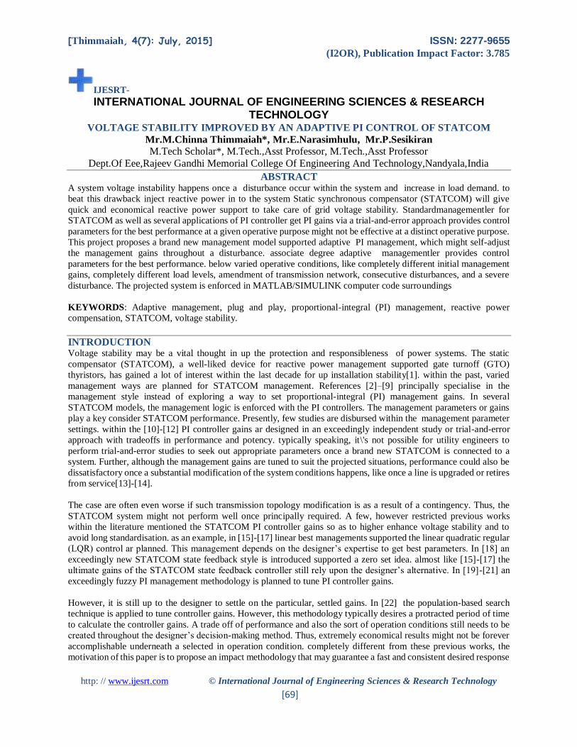
Fig. 5. Adaptive PI control algorithmflowchart
C. Flowcharts of the Adaptive PI Control Procedure
Fig.5 is an exemplary flowchart of the projected accommodative PI management for STATCOM for the diagram of
Fig. 3.
1.The accommodative PI management method begins at begin. The bus voltage over time 𝑉𝑚(𝑡) is sampled in line
with a desired rate. Then 𝑉𝑚(𝑡) is compared with 𝑉𝑠𝑠.If 𝑉𝑚(𝑡) = 𝑉𝑠𝑠, then there is no reason to alter any of the known
parameters Kp_V(t), Ki_V(t), Kp_I(t)and Ki_I(t).The power system is running swimmingly. On the opposite hand, if
𝑉𝑚(𝑡) ≠ 𝑉𝑠𝑠, then accommodative PI management begins.
2.The measured voltage is compared with 𝑉𝑟𝑒𝑓, the reference voltage outlined in (10). Then, Kp_V(t)and area unit
adjusted within the transformer block (outer loop) supported (23) and (24), that results in associate updated Iqref via
a current electrical circuit as showninFig.3
3.Then, the Iqrefis compared with the measured q-currentIqThe management gains Kp_I(t)and Ki_I(t)area unit adjusted
supported (25) and (26). Then, the phase α is decided and felt a electrical circuit for output, that basically decides the
reactive power output from the STATCOM.
4.Next, if |ΔV(t)|is not at intervals a tolerance threshold VЄ, which may be a terribly tiny price like 0.0001 p.u., the
transformer block and current regulator blocks area unit re-entered till the amendment is a smaller amount than the
given threshold VЄ. Thus, the values Kp_V(t), Ki_V(t), Kp_I(t)and Ki_I(t)are maintained
Fig. 6. Studied system
Page 8
[Thimmaiah, 4(7): July, 2015] ISSN: 2277-9655
(I2OR), Publication Impact Factor: 3.785
http: // www.ijesrt.com © International Journal of Engineering Sciences & Research Technology
[76]
If there is the necessity to unceasingly perform the voltage-control method, that is typically the case, then the method
returns to the measured bus voltage. Otherwise, the voltage-control method stops (i.e., the STATCOM management
is deactivated).
SIMULATION RESULTS
A.System Data
In the system simulation diagram shown in Fig. 6, a 100-MVAR STATCOM is enforced with a 48-pulse VSC and
connected to a 500-kV bus. this can be the quality sample STATCOM system in Matlab/Simulink library, and every
one machines utilized in the simulation square measure kinetic models. Here, the eye is concentrated on the
STATCOM management performance in bus voltage regulation mode. within the original model, the compensating
reactive power injection and therefore the regulation speed square measure chiefly suffering from PI controller
parameters within the transformer and therefore the current regulator. the first management are compared with the
planned adjustive PI management model. Assume the steady-state voltage,vss =1.0 p.u.
B.Response of the Original Model
In the original model,kp−v =12, ki−v =3000,kp−i =5, ki−I =40. Here, we have a tendency to keep all of the
parameters unchanged. The initial voltage supply, shown in Fig. 6, is 1 p.u., with the voltage base being 500 kV.
during this case, if we have a tendency to set 1, then we have the initial mvcalculated as mv =770.8780.
Voltage base being 500 kV. In this case, if we set R=1, then we have the initial mV calculated as mV= 770.8780.
Since,in this case, 𝛥𝑉(𝑡𝑜) = 𝛥𝑉𝑚𝑎𝑥 and kV =84.7425, based on(23)–(26), we have
Page 9
[Thimmaiah, 4(7): July, 2015] ISSN: 2277-9655
(I2OR), Publication Impact Factor: 3.785
http: // www.ijesrt.com © International Journal of Engineering Sciences & Research Technology
[77]
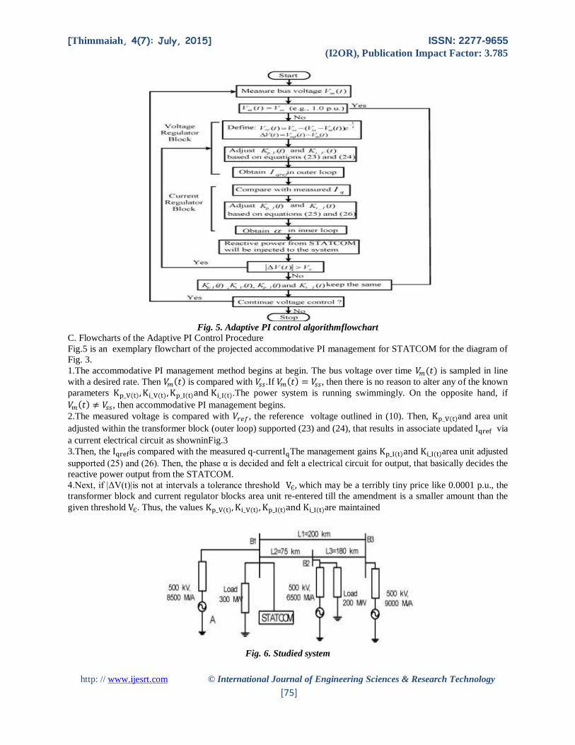
(b)
Fig. 7. Results of (a) voltages and (b) output reactive power using the same network and loads as in the original
system.
Fig. 8. Results of using the same network and loads as in the original system
(27)
(28)
(29)
(30)
Based on (27)–(30),theadjustive PI system is designed, and therefore the results square measure shown in Figs. 7 and
8, severally. Observations square measure summarized in Table I. From the results, It is obvious that the adjustive PI
management are able to do faster response than the first one. the mandatory reactive power quantity is that the same
whereas the adjustive PI approach runs quicker, because the voltage will. Set ωt=α+θ , where α is that the output angle
of this regulator, and is that the reference angle to the mensuration system.
In the STATCOM, it is that decides the management signal. Since θ could be a terribly giant worth (varying between
0 to 2Π ), the ripples of within the scale shown in Fig.8 will not have an effect on the ultimate simulation results.
Note that there is a awfully slight distinction of 0.12 MVar within the volt-ampere quantity at steady state in Table I,
that ought to be caused by process roundoff error. the explanation is that the sensitivity of dVAR/dV is around 100
MVar/0.011 p.u. of voltage. For simplicity, we have a tendency to might assume that sensitivity could be a linear
Page 10
[Thimmaiah, 4(7): July, 2015] ISSN: 2277-9655
(I2OR), Publication Impact Factor: 3.785
http: // www.ijesrt.com © International Journal of Engineering Sciences & Research Technology
[78]
perform. Thus, once the voltage error is 0.00001 p.u., Var is 0.0909 MVar, that is within the same vary because the
0.12-MVar match. Thus, it is affordable to conclude that the slight volt-ampere distinction in Table I is as a result of
spherical ∆var⁄∆voff error within the dynamic simulation that perpetually offers small ripples on the far side fifth
digits even within the final steadystate
C. Amendment of PI management Gains
During this state of affairs, the opposite system parameters stay unchanged whereas the PI managementler gains for
the first control square measure modified to kp−v,ki−v,kp−iand ki−i = 1. The dynamic management gains, that square
measure freelance of the initial values before the disturbance however rely upon the post fault conditions, square
measure given as
(31)
(32)
(33)
(34)
supported (31)–(34), the adjustive PI management model is designed, and therefore the results square measure shown
in Figs. 9 and 10, severally. From Fig. 9(a), it is discovered that once the PI management gains square measure
modified to completely different values, the first management model cannot create the bus voltage come back to to 1
p.u., and therefore the STATCOM has poor response. The reactive power cannot be multiplied to tier to satisfy the
necessity. However, with adjustive PI management, the STATCOM will answer disturbance absolutely as desired,
and therefore the voltage will come back to to 1 p.u. quickly at intervals 0.1 s. Fig. 9(b) conjointly shows that the
reactive power injection cannot be endlessly multiplied within the original management to support voltage, whereas
the adjustive PI management performs as desired.
. (a) (b)
Fig. 9. Results of (a) voltages and (b) output reactive power with changed PI control gains.
Page 11
[Thimmaiah, 4(7): July, 2015] ISSN: 2277-9655
(I2OR), Publication Impact Factor: 3.785
http: // www.ijesrt.com © International Journal of Engineering Sciences & Research Technology
[79]
Fig. 10. Results of α with changed PI control gains
D. Amendment of Load
In this case, the original PI controller gains are kept, which means kp−v,=12,ki−v, = 3000 kp−i = 5and
ki−i =40.However, the load at Bus B1 changes from 300 to 400 MW. during this case, we will have the given dynamic
management gains by
(35)
(36)
(37)
(38)
Based on (35)–(38), the adjustive PI management model is designed for automatic reaction to a amendment in
hundreds. The results square measure shown in Figs. 11 and 12. Table II shows some key observations of the
performance.
(b)
Fig. 11. Results of (a) voltages and (b) output reactive power with a change of load.
Page 12
[Thimmaiah, 4(7): July, 2015] ISSN: 2277-9655
(I2OR), Publication Impact Factor: 3.785
http: // www.ijesrt.com © International Journal of Engineering Sciences & Research Technology
[80]
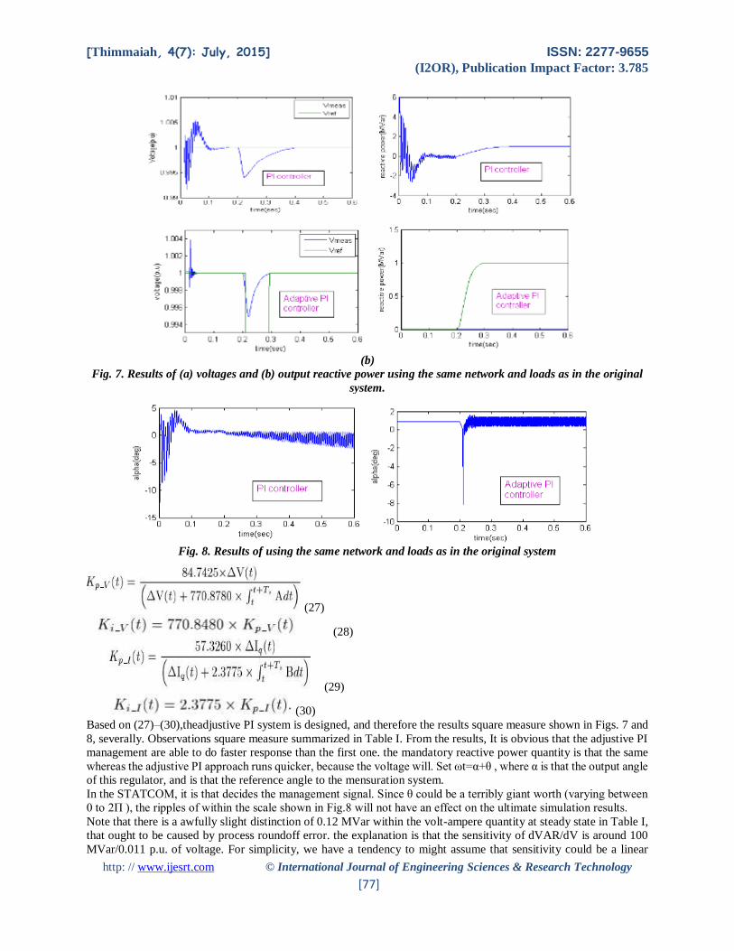
Fig. 12. Results of α with a change of load.
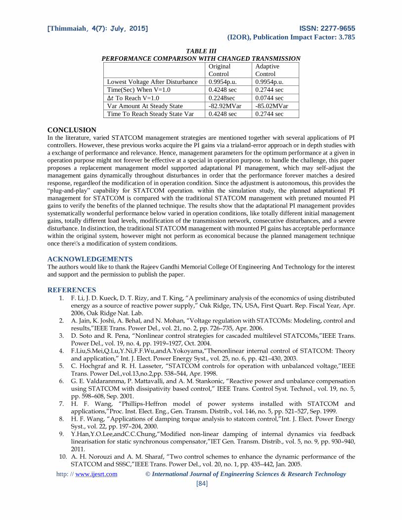
E. Amendment of Transmission Network
During this case, the PI controller gains stay unchanged, as within the original model. However, line one is shifted at
0.2 s to represent a unique network which might correspond to regular transmission maintenance. Here, we have
(40)
(41)
(42)
Based on (39)–(42), the adjustive PI management model is designed to mechanically react to changes within the
transmission network.The results are shown in Figs.13 and 14.
Note that the STATCOM absorbs volt-ampere from the system during this case. Here, the disturbance is assumed to
allow a voltage rise at (substation A) from 1.0 to 1.01 p.u.; meantime, the system features a line removed that tends
to lower the voltages. the general impact results in a voltage rise to on top of 1.0 at the controlled bus within the steady
state if the STATCOM is not activated. Thus, the STATCOM has to absorb volt-ampere within the final steady state
to achieve 1.0 p.u. voltage at the controlled bus. conjointly note that the initial transients forthwith when 0.2 s cause
associate degree over absorption by the STATCOM, whereas the adjustive PI management offers a way drum sander
and faster response, as shown in Fig. 13
Page 13
[Thimmaiah, 4(7): July, 2015] ISSN: 2277-9655
(I2OR), Publication Impact Factor: 3.785
http: // www.ijesrt.com © International Journal of Engineering Sciences & Research Technology
[81]
(a) (b)
Fig. 13. Results of (a) voltages and (b) output reactive power with a change of transmission network.
Fig. 14. Results of α with a change of transmission network.
F.Two Consecutive Disturbances
During this case, a disturbance at 0.2 s causes a voltage decrease from 1.0 to 0.989 p.u. and it happens at station A.
After that, line one is shifted at 0.25 s. The results square measure shown in Figs. 15 and 16. From Fig. 15, it is
apparent that the adjustive PI management are able to do a lot of faster response than the first one, that makes the
system free fall a lot of but the first management throughout the second disturbance. Note in Fig. 15(a) that the most
important free fall throughout the second disturbance event (startingat 0.25s) with the first management is 0.012 p.u.,
whereas it is 0.006 p.u. with the planned adjustive management. Therefore, the system is a lot of sturdy in responding
to consecutive disturbances with adjustive PI management
.
Page 14
[Thimmaiah, 4(7): July, 2015] ISSN: 2277-9655
(I2OR), Publication Impact Factor: 3.785
http: // www.ijesrt.com © International Journal of Engineering Sciences & Research Technology
[82]
(a) (b)
Fig. 15. Results of (a) voltages and (b) output reactive power with two consecutive disturbances.
Fig. 16. Results of α with two consecutive disturbances
G. Severe Disturbance
During this case, a severe disturbance at 0.2 s causes a voltage decrease from 1.0 to 0.6 p.u. and it happens at station
A. After that, the disturbance is cleared at 0.25 s. The results square measure shown in Figs. 17 and 18. as a result of
the limit of STATCOM capability, the voltage cannot come back to to one p.u. when the severe free fall to 0.6 p.u.
when the disturbance is cleared at 0.25 s, the voltage goes back to around 1.0 p.u. As shown in Fig. 17(a) and therefore
the 2 insets, the adjustive PI management will bring the voltage back to 1.0 p.u. a lot of faster and drum sander than
the first one. a lot of vital, the Q curve within the adjustive management (Qmax = 40 MVar) is way but the Q within
the original management Qmax =118 MVar).
Page 15
[Thimmaiah, 4(7): July, 2015] ISSN: 2277-9655
(I2OR), Publication Impact Factor: 3.785
http: // www.ijesrt.com © International Journal of Engineering Sciences & Research Technology
[83]
(b)
Fig. 17. Results of (a) voltages and (b) output reactive power in a severe disturbance
Fig. 18. Results of alpha in a severe disturbance
TABLES
TABLE I
PERFORMANCE COMPARISON FOR THE ORIGINAL SYSTEM PARAMETERS
Original
Control
Adaptive
Control
Lowest Voltage After Disturbance 0.9938 p.u. 0.9938 p.u.
Time(Sec) When V=1.0 0.4095 sec 0.2983 sec
∆𝑇 To Reach V=1.0 0.2095 sec 0.0983 sec
Var Amount At Steady State 97.76 MVar 97.65 MVar
Time To Reach Steady State Var 0.4095 sec 0.2983 sec
TABLE II
PERFORMANCE COMPARISON WITH A CHANGE OF LOAD
Original
Control
Adaptive
Control
Lowest Voltage After Disturbance 0.9949p.u. 0.9949p.u.
Time(Sec) When V=1.0 0.4338 sec 0.3125 sec
∆𝑡 To Reach V=1.0 0.2338 sec 0.1125 sec
Var Amount At Steady State 93.08MVar 92.72MVar
Time To Reach Steady State Var 0.4338 sec 0.3125 sec
Page 16
[Thimmaiah, 4(7): July, 2015] ISSN: 2277-9655
(I2OR), Publication Impact Factor: 3.785
http: // www.ijesrt.com © International Journal of Engineering Sciences & Research Technology
[84]
TABLE III
PERFORMANCE COMPARISON WITH CHANGED TRANSMISSION
Original
Control
Adaptive
Control
Lowest Voltage After Disturbance 0.9954p.u. 0.9954p.u.
Time(Sec) When V=1.0 0.4248 sec 0.2744 sec
∆𝑡 To Reach V=1.0 0.2248sec 0.0744 sec
Var Amount At Steady State -82.92MVar -85.02MVar
Time To Reach Steady State Var 0.4248 sec 0.2744 sec
CONCLUSION In the literature, varied STATCOM management strategies are mentioned together with several applications of PI
controllers. However, these previous works acquire the PI gains via a trialand-error approach or in depth studies with
a exchange of performance and relevance. Hence, management parameters for the optimum performance at a given in
operation purpose might not forever be effective at a special in operation purpose. to handle the challenge, this paper
proposes a replacement management model supported adaptational PI management, which may self-adjust the
management gains dynamically throughout disturbances in order that the performance forever matches a desired
response, regardleof the modification of in operation condition. Since the adjustment is autonomous, this provides the
“plug-and-play” capability for STATCOM operation. within the simulation study, the planned adaptational PI
management for STATCOM is compared with the traditional STATCOM management with pretuned mounted PI
gains to verify the benefits of the planned technique. The results show that the adaptational PI management provides
systematically wonderful performance below varied in operation conditions, like totally different initial management
gains, totally different load levels, modification of the transmission network, consecutive disturbances, and a severe
disturbance. In distinction, the traditional STATCOM management with mounted PI gains has acceptable performance
within the original system, however might not perform as economical because the planned management technique
once there\'s a modification of system conditions.
ACKNOWLEDGEMENTS The authors would like to thank the Rajeev Gandhi Memorial College Of Engineering And Technology for the interest
and support and the permission to publish the paper.
REFERENCES 1. F. Li, J. D. Kueck, D. T. Rizy, and T. King, “A preliminary analysis of the economics of using distributed
energy as a source of reactive power supply,” Oak Ridge, TN, USA, First Quart. Rep. Fiscal Year, Apr. 2006, Oak Ridge Nat. Lab.
2. A. Jain, K. Joshi, A. Behal, and N. Mohan, “Voltage regulation with STATCOMs: Modeling, control and results,”IEEE Trans. Power Del., vol. 21, no. 2, pp. 726–735, Apr. 2006.
3. D. Soto and R. Pena, “Nonlinear control strategies for cascaded multilevel STATCOMs,”IEEE Trans. Power Del., vol. 19, no. 4, pp. 1919–1927, Oct. 2004.
4. F.Liu,S.Mei,Q.Lu,Y.Ni,F.F.Wu,andA.Yokoyama,“Thenonlinear internal control of STATCOM: Theory and application,” Int. J. Elect. Power Energy Syst., vol. 25, no. 6, pp. 421–430, 2003.
5. C. Hochgraf and R. H. Lasseter, “STATCOM controls for operation with unbalanced voltage,”IEEE Trans. Power Del.,vol.13,no.2,pp. 538–544, Apr. 1998.
6. G. E. Valdarannma, P. Mattavalli, and A. M. Stankonic, “Reactive power and unbalance compensation using STATCOM with dissipativity based control,” IEEE Trans. Control Syst. Technol., vol. 19, no. 5, pp. 598–608, Sep. 2001.
7. H. F. Wang, “Phillips-Heffron model of power systems installed with STATCOM and applications,”Proc. Inst. Elect. Eng., Gen. Transm. Distrib., vol. 146, no. 5, pp. 521–527, Sep. 1999.
8. H. F. Wang, “Applications of damping torque analysis to statcom control,”Int. J. Elect. Power Energy Syst., vol. 22, pp. 197–204, 2000.
9. Y.Han,Y.O.Lee,andC.C.Chung,“Modified non-linear damping of internal dynamics via feedback linearisation for static synchronous compensator,”IET Gen. Transm. Distrib., vol. 5, no. 9, pp. 930–940, 2011.
10. A. H. Norouzi and A. M. Sharaf, “Two control schemes to enhance the dynamic performance of the STATCOM and SSSC,”IEEE Trans. Power Del., vol. 20, no. 1, pp. 435–442, Jan. 2005.
Page 17
[Thimmaiah, 4(7): July, 2015] ISSN: 2277-9655
(I2OR), Publication Impact Factor: 3.785
http: // www.ijesrt.com © International Journal of Engineering Sciences & Research Technology
[85]
11. M. S. E. Moursi and A. M. Sharaf, “Novel controllers for the 48-pulse VSC STATCOM and SSSC for voltage regulation and reactive power compensation,”IEEE Trans. Power Syst., vol. 20, no. 4, pp. 1985–1997, Nov. 2005.
12. Matlab& Simulink, GTO-based STATCOM Dec. 2013. [Online]. Available: http://www.mathworks.com/help/physmod/sps/powersys/ug/gto-based-statcom.html, Feb. 2012
13. H. Li, F. Li, J. D. Kueck, and D. T. Rizy, “Adaptive voltage control with distributed energy resources: Algorithm, theoretical analysis, simulation and field test verification,”IEEE Trans. Power Syst., vol. 25, no. 3, pp. 1638–1647, Aug. 2010.
14. H. Li, F. Li, Y. Xu, D. T. Rizy, and S. Adhikari, “Autonomous and adaptive voltage control using multiple distributed energy resources,” IEEE Trans. Power Syst., vol. 28, no. 2, pp. 718–730, May 2013.
15. P. Rao, M. L. Crow, and Z. Yang, “STATCOM control for power system voltage control applications,” IEEE Trans. Power Del., vol. 15, no. 4, pp. 1311–1317, Oct. 2000.
16. W. L. Chen and Y. Y. Hsu, “Controller design for an induction generator driven by a variable speed wind turbine,”IEEE Trans. Energy Convers., vol. 21, no. 3, pp. 625–635, Sep. 2006.
17. K. Wang and M. L. Crow, “Power system voltage regulation via STATCOM internal nonlinear control,”IEEE Trans. Power Syst., vol. 26, no. 3, pp. 1252–1262, Aug. 2011.
18. V. Spitsa, A. Alexandrovitz, and E. Zeheb, “Design of a robust state feedback controller for a STATCOM using a zero set concept,”IEEE Trans. Power Del., vol. 25, no. 1, pp. 456–467, Jan. 2010.
19. A. Luo, C. Tang, Z. Shuai, J. Tang, X. Y. Xu, and D. Chen, “Fuzzy-PIbased direct-output-voltage control strategy for the STATCOM used in utility distribution systems,”IEEE Trans. Ind. Electron.,vol.56,no.1, pp. 2401–2411, Jul. 2009.
20. A. H. M. A. Rahim, E. P. Nowicki, and J. M. Bakhashwain, “Fuzzy STATCOM control strategies for power system stabilization,” inProc. ICGST Int. J. Autom. Control Syst. Eng., Feb. 2006, pp. 41–48.
21. L. O. Mak, Y. X. Ni, and C. M. Shen, “STATCOM with fuzzy controllers for interconnected power systems,”Elect. Power Syst. Res., vol. 55, pp. 87–95, 2000.
22. C.-H. Liu and Y.-Y. Hsu, “Design of a self-tuning PI controller for a STATCOM using particle swarm optimization,”IEEE Trans. Ind. Electron., vol. 57, no. 2, pp. 702–715, Feb. 2010.
23. C. Schauder and H. Mehta, “Vector analysis and control of the advanced static VAr compensators,” Proc. Inst. Elect. Eng., Gen., Transm.,Distrib., vol. 140, no. 4, pp. 299–306, Jul. 1993.
24. I. Papic, P. Zunko, and D. Povh, “Basic control of unified powerflowcontroller,”IEEE Trans. Power Syst., vol. 12, no. 4, pp. 1734–1739, Nov. 1997.
25. K. K. Sen, “Static synchronous compensator—Theory, modeling and applications,” presented at the IEEE Power Eng. Soc. Winter Meeting, Edmonton, AB, Canada, Jan. 1999.


![IJESRT /Archive-2016/April-2016/68_EFFECT OF... · [Deepali*, 5(4): April, 2016] ISSN: 2277-9655 (I2OR), Publication Impact Factor: 3.785 http: // © International Journal of Engineering](https://static.documents.pub/doc/80x56/5b52380b7f8b9a7b648d0242/archive-2016april-201668effect-of-deepali-54-april-2016-issn.jpg)
![IC™ Value: 3.00 IJESRT /Archive-2018/April-2018...http: // © International Journal of Engineering Sciences & Research Technology [836] Ground mounted/conventional and based solar](https://static.documents.pub/doc/80x56/5f4c538784fdef644f668974/ica-value-300-archive-2018april-2018-http-international-journal.jpg)


![IJESRT /Archives-2015/July-2015/35_QFD... · http: // © International Journal of Engineering Sciences & Research Technology [249] IJESRT ... (Jnanesh & Hebbar, 2008). Total Quality](https://static.documents.pub/doc/80x56/5ad42c787f8b9a571e8be123/archives-2015july-201535qfdhttp-international-journal-of-engineering.jpg)


