International Journal of Scientific and Research Publications, Volume 3, Issue 3, March 2013 1 ISSN 2250-3153 www.ijsrp.org Power System Stability Enhancement under Three Phase Fault with FACTS Devices TCSC, STATCOM and UPFC Dr. S. Titus * , B.J.Vinothbabu ** , I. Maria Anton Nishanth ** * Member, IEEE, Department of EEE, MAM college of Engineering, Trichirappalli, India ** Department of EEE, MAM college of Engineering, Trichirappalli, India *** Department of EEE, MAM college of Engineering, Trichirappalli, India Abstract- With the ever increasing complexities in power systems across the globe and the growing need to provide stable, secure, controlled, economic and high quality power especially in the deregulated power market. It is envisaged that FACTS controllers will play a vital role in power systems. This paper investigates the improvement of transient stability of a test system under three phase fault using facts devise. TCSC- Thyristor Controlled Series Capacitor and STATCOM- Static Synchronous Compensator are utilized as a series and shunt compensation respectively. UPFC-Unified Power Flow Controller is considered as a shunt-series compensator. Index Terms- TCSC; STATCOM; UPFC; Transient stability. I. INTRODUCTION oday’s power system is a complex network comprising of generator, transmission lines, variety of loads and transformers. With the ever increase in power demand some transmission line is more loaded than was planned when they were built [1]. With increased loading of long transmission line the problem of transient stability after major disturbance, will cause the entire system to subside. Power system stability is the ability of electric power system, for a given initial operating condition to regain a state of operating equilibrium after being subjected to a physical disturbance, with most system variables bounded so that practically the entire system remains intact [2]. And the main challenges of modern power system is transient stability is referred as the capability of the system to maintain synchronous operation in the event of large disturbance and this kind of stability depends on parameters of system and intensity of disturbance [3] [4]. The recent development of power electronics introduces the use of flexible ac transmission system (FACTS) controllers in power system [5]. FACTS technology provides the opportunity to [6] [7]– Increase loading capacity of transmission lines. Prevent blackouts. Improve generation productivity. Reduce circulating reactive power. Improves system stability limit. Reduce voltage flicker. Reduce system damping and oscillations. Control power flow so that it flows through the designated routes. Congestion management The conventional control devices like synchronous condenser, saturated reactor, thyristor controlled reactor, fixed capacitor thyristor controlled reactor, thyristor switched capacitor having less system stability limit, less enhancement of system damping, less voltage flicker control when compared to emerging facts devices like TCSC, STATCOM and UPFC [8][9]. This paper investigates the improvement of system stability with various emerging FACTS devices and their comparisons. [10] - [13] II. DESCRIPTION OF FACTS DEVICES A. TCSC The basic conceptual TCSC module comprises a series capacitor, C, in parallel with a thyristor-controlled reactor, LS, as shown in Fig.1. A TCSC is a series-controlled capacitive reactance that can provide continuous control of power on the ac line over a wide range. The principle of variable-series compensation is simply to increase the fundamental-frequency voltage across an fixed capacitor in a series compensated line through appropriate variation of the firing angle. This enhanced voltage changes the effective value of the series-capacitive reactance and control the reactive power [9] [14]. B. STATCOM STATCOM is a controlled reactive-power source. It provides the desired reactive-power generation and absorption entirely by means of electronic processing of the voltage and current waveforms in a voltage-source converter (VSC). A single-line STATCOM power circuit is shown in Fig.2 Figure1-Configuration of TCSC T
Transcript
International Journal of Scientific and Research Publications, Volume 3, Issue 3, March 2013 1 ISSN 2250-3153
www.ijsrp.org
Power System Stability Enhancement under Three Phase
Fault with FACTS Devices TCSC, STATCOM and UPFC
Dr. S. Titus*, B.J.Vinothbabu
**, I. Maria Anton Nishanth
**
* Member, IEEE, Department of EEE, MAM college of Engineering, Trichirappalli, India
** Department of EEE, MAM college of Engineering, Trichirappalli, India *** Department of EEE, MAM college of Engineering, Trichirappalli, India
Abstract- With the ever increasing complexities in power
systems across the globe and the growing need to provide stable,
secure, controlled, economic and high quality power especially in
the deregulated power market. It is envisaged that FACTS
controllers will play a vital role in power systems. This paper
investigates the improvement of transient stability of a test
system under three phase fault using facts devise. TCSC-
Thyristor Controlled Series Capacitor and STATCOM- Static
Synchronous Compensator are utilized as a series and shunt
compensation respectively. UPFC-Unified Power Flow
Controller is considered as a shunt-series compensator.
Index Terms- TCSC; STATCOM; UPFC; Transient stability.
I. INTRODUCTION
oday’s power system is a complex network comprising of
generator, transmission lines, variety of loads and
transformers. With the ever increase in power demand some
transmission line is more loaded than was planned when they
were built [1]. With increased loading of long transmission line
the problem of transient stability after major disturbance, will
cause the entire system to subside. Power system stability is the
ability of electric power system, for a given initial operating
condition to regain a state of operating equilibrium after being
subjected to a physical disturbance, with most system variables
bounded so that practically the entire system remains intact [2].
And the main challenges of modern power system is transient
stability is referred as the capability of the system to maintain
synchronous operation in the event of large disturbance and this
kind of stability depends on parameters of system and intensity
of disturbance [3] [4].
The recent development of power electronics introduces
the use of flexible ac transmission system (FACTS) controllers in
power system [5]. FACTS technology provides the opportunity
having less system stability limit, less enhancement of system
damping, less voltage flicker control when compared to
emerging facts devices like TCSC, STATCOM and UPFC [8][9].
This paper investigates the improvement of system stability with
various emerging FACTS devices and their comparisons. [10] -
[13]
II. DESCRIPTION OF FACTS DEVICES
A. TCSC
The basic conceptual TCSC module comprises a series
capacitor, C, in parallel with a thyristor-controlled reactor, LS, as
shown in Fig.1. A TCSC is a series-controlled capacitive
reactance that can provide continuous control of power on the ac
line over a wide range. The principle of variable-series
compensation is simply to increase the fundamental-frequency
voltage across an fixed capacitor in a series compensated line
through appropriate variation of the firing angle. This enhanced
voltage changes the effective value of the series-capacitive
reactance and control the reactive power [9] [14].
B. STATCOM
STATCOM is a controlled reactive-power source. It
provides the desired reactive-power generation and absorption
entirely by means of electronic processing of the voltage and
current waveforms in a voltage-source converter (VSC). A
single-line STATCOM power circuit is shown in Fig.2
Figure1-Configuration of TCSC
T
International Journal of Scientific and Research Publications, Volume 3, Issue 3, March 2013 2
ISSN 2250-3153
www.ijsrp.org
Figure 2-Configuartion of STATCOM
where a VSC is connected to a utility bus through
magnetic coupling. The exchange of reactive power between the
converter and the ac system can be controlled by varying the
amplitude of the 3-phase output voltage, Es, of the converter.
That is, if the amplitude of the output voltage is increased above
that of the utility bus voltage, Et, then a current flows through the
reactance from the converter to the ac system and the converter
generates capacitive-reactive power for the ac system. If the
amplitude of the output voltage is decreased below the utility bus
voltage, then the current flows from the ac system to the
converter and the converter absorbs inductive-reactive power
from the ac system. If the output voltage equals the ac system
voltage, the reactive-power exchange becomes zero, in which
case the STATCOM is said to be in a floating state [9] [15] –
[16].
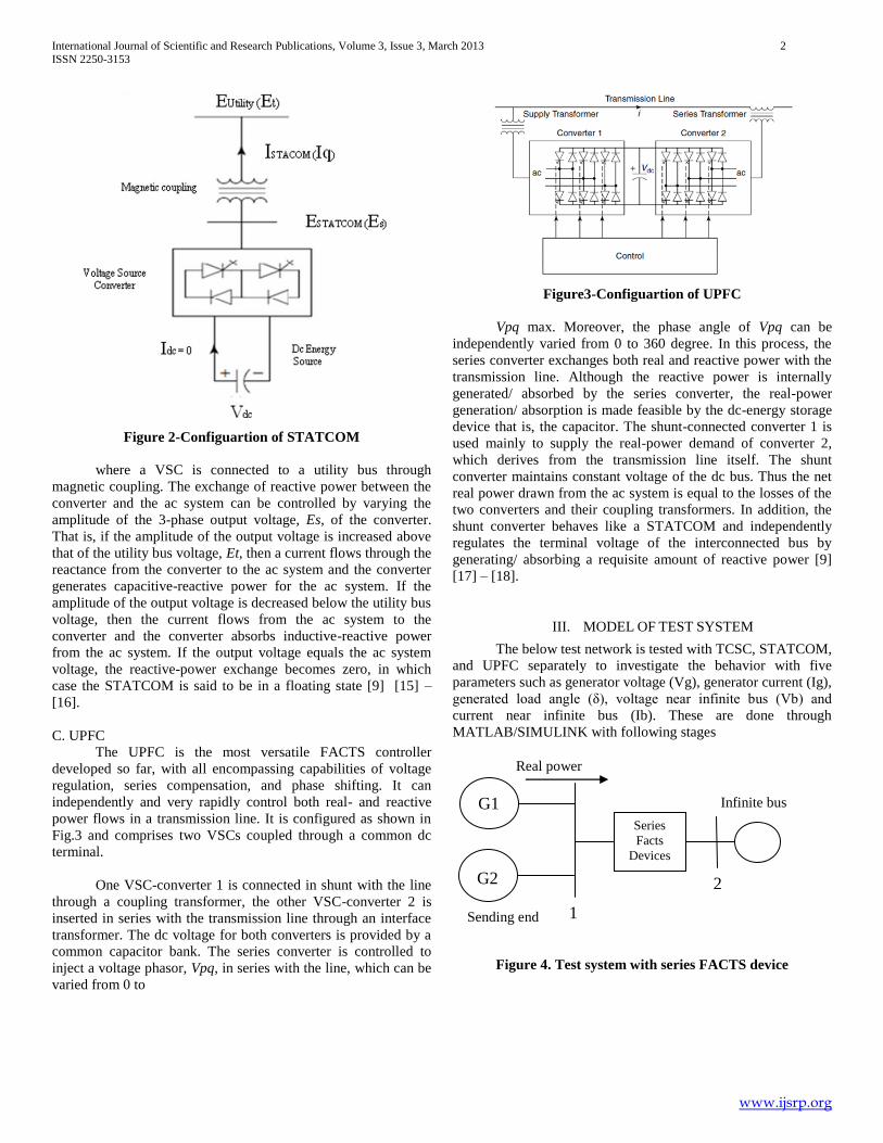
C. UPFC
The UPFC is the most versatile FACTS controller
developed so far, with all encompassing capabilities of voltage
regulation, series compensation, and phase shifting. It can
independently and very rapidly control both real- and reactive
power flows in a transmission line. It is configured as shown in
Fig.3 and comprises two VSCs coupled through a common dc
terminal.
One VSC-converter 1 is connected in shunt with the line
through a coupling transformer, the other VSC-converter 2 is
inserted in series with the transmission line through an interface
transformer. The dc voltage for both converters is provided by a
common capacitor bank. The series converter is controlled to
inject a voltage phasor, Vpq, in series with the line, which can be
varied from 0 to
Figure3-Configuartion of UPFC
Vpq max. Moreover, the phase angle of Vpq can be
independently varied from 0 to 360 degree. In this process, the
series converter exchanges both real and reactive power with the
transmission line. Although the reactive power is internally
generated/ absorbed by the series converter, the real-power
generation/ absorption is made feasible by the dc-energy storage
device that is, the capacitor. The shunt-connected converter 1 is
used mainly to supply the real-power demand of converter 2,
which derives from the transmission line itself. The shunt
converter maintains constant voltage of the dc bus. Thus the net
real power drawn from the ac system is equal to the losses of the
two converters and their coupling transformers. In addition, the
shunt converter behaves like a STATCOM and independently
regulates the terminal voltage of the interconnected bus by
generating/ absorbing a requisite amount of reactive power [9]
[17] – [18].
III. MODEL OF TEST SYSTEM
The below test network is tested with TCSC, STATCOM,
and UPFC separately to investigate the behavior with five
parameters such as generator voltage (Vg), generator current (Ig),
generated load angle (δ), voltage near infinite bus (Vb) and
current near infinite bus (Ib). These are done through
MATLAB/SIMULINK with following stages
Figure 4. Test system with series FACTS device
G1
G2
1
2
Infinite bus
Sending end
Real power
Series
Facts
Devices
International Journal of Scientific and Research Publications, Volume 3, Issue 3, March 2013 3
ISSN 2250-3153
www.ijsrp.org
Figure 5. Test system with shunt FACTS device
Stage 1 -To design test system shown in fig 6.
Stage 2 - To measure five parameters under normal
operating condition.
Stage 3 -To create three phase fault near to infinite bus
in test system. Fault duration 0.5 to 0.6 seconds. Shown
in fig 7.
Stage 4- To measure five parameters under three phase
fault conditions
Stage 5 - To design FACTS devices (TCSC,
STATCOM and UPFC) Shown in fig 8, fig 9 and fig 10
respectively.
Stage 6- To connect FACTS devices (0.6 to0.8 seconds)
in test system under three phase fault condition and to
measure behavioral change of system.
The test system specification is
Generator 1, 2 - 10KV, 110MW, 300 rpm,
TCSC - 10MVAR, 10KV,
STATCOM - 10MVAR, 10KV and
UPFC - 10MVAR, 10KV.
IV. RESULT AND DISCUSSION
In accordance with the above SIMULINK work the five
different parameters - generator voltage (Vg), generator current
(Ig), generated load angle (δ), voltage near infinite bus (Vb) and
current near infinite bus (Ib) of test system is measured and the
settling time of each parameter is calculated for system stability
and also to maximize the power flow in transmission line.
The simulation result for generator voltage (Vg) of phase A is
shown in fig 11. It is clear that under three phase fault, without
FACTS device the voltage fluctuation of generator is more,
whereas, it is less when the FACTS devices are involved. A table
for generator voltage (Vg) under different time interval is
constructed from the observed result. During the time interval of
0.5 to 0.8 seconds and 0.8 to 3.2 seconds the voltage rises from
3200 to 5000 volts and from 5000 to 8000 volts respectively
which is greater than the generator voltage (Vg) without the
involvement of FACTS device. So, when FACTS devices are
connected to the system, it takes 2.4 seconds for TCSC, 2.0
seconds for STATCOM and 1.4 seconds for UPFC to reach the
stability level.
Figure 11. Simulation Result for Generator Voltage (Vg)
Table 1. Generator Voltage (Vg) in volts
Gen
era
tor
Vo
lta
ge
(Vg
) in
vo
lts
Time in
seconds
0 to
0.5
0.5
to
0.6
0.6
to
0.8
0.8
to
3.2
3.2 to
10
Without
FACTS
device
0 to
5000
2000
to 0 4000 4000
4000
to
11000
TCSC 0 to
5000 3200
3200
to
5000
5000
to
8000
8000
STATCOM 0 to
5000 3200
3200
to
5000
5000
to
7000
7000
to
8000
UPFC 0 to
5000 3200
3200
to
5000
5000
to
7600
7600
to
8000
The fig 12 shows the generator current (Ig) of phase A.
The generator current (Ig) is reached to stable at 4.4 seconds
when the FACTS devices are not connected. After incorporating
the FACTS devices TCSC, STATCOM and UPFC, the settling
time of generator current (Ig) is reduced as 2.4, 3.4 and 2.3
seconds respectively for reaching the stable condition, Which is
understood through table 2.
G1
G2
1
2
Infinite bus
Sending end
Real power
Shunt
Facts
Devices
International Journal of Scientific and Research Publications, Volume 3, Issue 3, March 2013 4
ISSN 2250-3153
www.ijsrp.org
Figure 12. Simulation Result for Generator Current (Ig)
Table 2. Generator Current (Ig) in Amps
Gen
era
tor
Cu
rren
t (I
g)
in A
mp
eres
Time in
seconds
0 to
0.5
0.5
to
0.6
0.6
to
0.8
0.8
to
3.2
3.2
to 10
Without
FACTS
device
1500
to
1250
5000 1500 1500
1500
to
1050
TCSC
800
to
750
200 1000
1000
to
700
700
STATCOM
800
to
750
200 800
800
to
700
700
UPFC
800
to
750
200 800
800
to
700
700
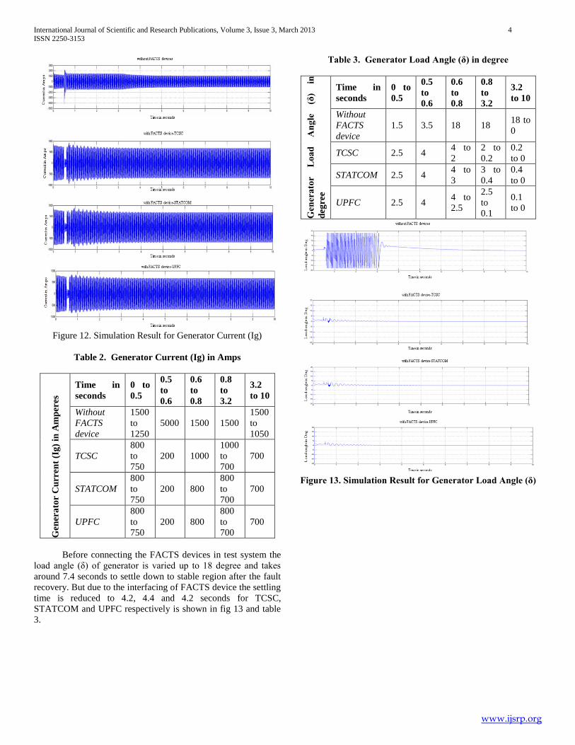
Before connecting the FACTS devices in test system the
load angle (δ) of generator is varied up to 18 degree and takes
around 7.4 seconds to settle down to stable region after the fault
recovery. But due to the interfacing of FACTS device the settling
time is reduced to 4.2, 4.4 and 4.2 seconds for TCSC,
STATCOM and UPFC respectively is shown in fig 13 and table
3.
Table 3. Generator Load Angle (δ) in degree
Gen
era
tor
Lo
ad
A
ng
le
(δ)
in
deg
ree
Time in
seconds
0 to
0.5
0.5
to
0.6
0.6
to
0.8
0.8
to
3.2
3.2
to 10
Without
FACTS
device
1.5 3.5 18 18 18 to
0
TCSC 2.5 4 4 to
2
2 to
0.2
0.2
to 0
STATCOM 2.5 4 4 to
3
3 to
0.4
0.4
to 0
UPFC 2.5 4 4 to
2.5
2.5
to
0.1
0.1
to 0
Figure 13. Simulation Result for Generator Load Angle (δ)
International Journal of Scientific and Research Publications, Volume 3, Issue 3, March 2013 5
ISSN 2250-3153
www.ijsrp.org
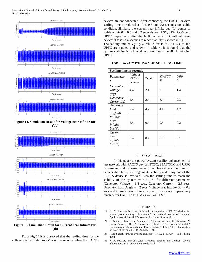
Figure 14. Simulation Result for Voltage near Infinite Bus
(Vb)
Figure 15. Simulation Result for Current near Infinite Bus
(Ib)
From Fig 14 it is observed that the settling time for the
voltage near infinite bus (Vb) is 5.4 seconds when the FACTS
devices are not connected. After connecting the FACTS devices
settling time is reduced as 0.4, 0.5 and 0.2 seconds for stable
condition. Similarly the current near infinite bus (Ib) comes to
stable within 0.4, 0.5 and 0.2 seconds for TCSC, STATCOM and
UPFC respectively after the fault recovery. But without those
devices it takes 3.4 seconds to reach stability is shown in fig 15.
The settling time of Vg, Ig, δ, Vb, Ib for TCSC, STACOM and
UPFC are studied and shown in table 4. It is found that the
system stability is achieved in short interval while interfacing
UPFC.
TABLE 5. COMPARISON OF SETTLING TIME
Settling time in seconds
Parameter
s
Without
FACTS
devices
TCSC STATCO
M
UPF
C
Generator
voltage
(Vg)
4.4 2.4 2 1.4
Generator
Current(Ig) 4.4 2.4 3.4 2.3
Generator
load
angle(δ)
7.4 4.2 4.4 4.2
Voltage
near
infinite
bus(Vb)
5.4 0.4 0.5 0.2
Current
near
infinite
bus(Ib)
3.4 0.4 0.5 0.1
V. CONCLUSION
In this paper the power system stability enhancement of
test network with FACTS devices TCSC, STATCOM and UPFC
is presented and discussed under three phase short circuit fault. It
is clear that the system regains its stability under any one of the
FACTS device is involved. Also the settling time to reach the
stability of the system with UPFC for different parameters
(Generator Voltage – 1.4 secs, Generator Current – 2.3 secs,
Generator Load Angle – 4.2 secs, Voltage near Infinite Bus – 0.2
secs and Current near Infinite Bus – 0.1 secs) is comparatively
much better than STATCOM as well as TCSC.
REFERENCES
[1] Dr. M. Rajaram, N. Reka, D. Murali, “Comparison of FACTS devices for power system stability enhancement,” International Journal of Computer Applications (0975 – 8887), volume 8 – No. 4, October 2010.
[2] P. Kundur, J. Paserba, V. Ajjarapu, G. Anderson, A. Bose, C. Canizares, N. Hatziargyriou, D. Hill, A. Stankovac, C. Taylor, T. V. Custem, V. Vittal, “ Defenition and Classification of Power System Stability,” IEEE Transaction on Power System, 2004, 19(2)..1387 - 1401
[3] Hadi Saadat, “Power system analysis,” TATA McGraw – Hill edition, 2002.
[4] K. R. Padiyar, “Power System Dynamic Stability and Control,” second edition 2002, B. S. publication, Hyderabad
International Journal of Scientific and Research Publications, Volume 3, Issue 3, March 2013 6
ISSN 2250-3153
www.ijsrp.org
[5] S. K. Srivasta, “ Advanced Power Electronics Based Facts Controllers and Overview,” Asian Power Electronics Journal, volume 4, No. 3 December 2010.
[6] Chintu Rza Makkar, Lillie Dewan, “Transient stability enhancement using robust FACTS controllers – a brief tour,” Canadian Journal on Electrical & Electronics Engineering volume 1, No. 7, December 2010.
[7] Amit Garg, Sanjay Kumar Agarwal, “ Voltage Control and Dynamic Performance of Power Transmission System using STATCOM and its Comparison with SVC”, International Journal of Advances in Engineering and Technology, January 2012.
[8] Enrique Acha, Claudio R. Fuerte – Esquivel, Hugo Ambriz – Perez, Cesar Angeles – Camacho, “FACTS Modelling and Simulation in Power Networks,” John Wiley & sons LTD, 2004.
[9] R. Mohan Mathur, Rajiv K. Varma, “Thyristor Based FACTS Controllers for Electrical Transmission Systems,” IEEE press series on Power Engineering, John Wiley & Sons LTD, 2002.
[10] S. Shankar, S. Balaji, S. Arul, “Simulation and Comparison of Various FACTS devices in power system,” International Journal of Engineering Science and Technology, volume 2 (4), 2010, 538 – 547.
[11] Alireza Seifi, Sasan Gholami, Amin Shabanpour, “Power Flow Studt and Comparison of FACTS: Series (SSSC), Shunt (STATCOM) and shunt – series (UPFC),” The Pacific Journal of Science and Technology volume 11. No. 1. May 2010 (spring).
[12] Arthitsode – Yome, N. Mithulananthan, “ Comparison of Shunt Capacitor, SVC and STATCOM in Static Voltage Stability Margin Enhancement,” International Journal of Electrical Engineering Education, 41/2.
[13] J. Barati, A. Saeedian, S. S. Mortazavi, “ Damping Power System Oscillation Improvement by FACTS Devices: A Comparison between SSSC and STATCOM,” Worl Acadamy of Science, Engineering and Technology 62 2010.
[14] A. Kazemi, B. Badrzadeh, “ Modelling and Simulation of SVC and TCSC to Study their Limits on Maximum Loadability Point,” Electrical Power and Energy System 26 (2004) 381 – 388, Elsevier LTD.
[15] P. Venkata Kishore, Dr. S. Rama Reddy, “ Voltage Sag Mitigation in Eight Bus System using D – STATCOM for Power Quality Improvement,” International Journal of Engineering Science and Technology, volume 2 (4), 2010, 529 – 537.
[16] Sayed Mojtaba Shirvani Boroujeni, Reza Hemmati, Hamideh Delafkar, Elahe Behzadipour, “ Voltage Support and Stability Enhancement using STATCOM,” American Journal of Scientific Research, Euro Journal Publishing , 2011.
[17] N. Dizdarebic, G. Anderson, “ Power Flow Regulation by use of UPFC’s Injection Model,” IEEE Power Tech 99 Conference, 1999.
[18] S. Muthu Krishnan, Dr. A. Nirmal Kumar Comparison of Simulation and Experimental Results of UPFC used for Power Quality Improvement,” International Journal of Computer and Electrical Engineering, volume 2, No. 3, June 2010.
AUTHORS
First Author – Dr. S. Titus, Member, IEEE, Department of EEE,
MAM college of Engineering, Trichirappalli, India, E-mail:


![1 1 1 1 1 1 1 ¢ 1 1 1 - pdfs.semanticscholar.org€¦ · 1 1 1 [ v . ] v 1 1 ¢ 1 1 1 1 ý y þ ï 1 1 1 ð 1 1 1 1 1 x ...](https://static.documents.pub/doc/80x56/5f7bc722cb31ab243d422a20/1-1-1-1-1-1-1-1-1-1-pdfs-1-1-1-v-v-1-1-1-1-1-1-y-1-1-1-.jpg)

![1 $SU VW (G +LWDFKL +HDOWKFDUH %XVLQHVV 8QLW 1 X ñ 1 … · 2020. 5. 26. · 1 1 1 1 1 x 1 1 , x _ y ] 1 1 1 1 1 1 ¢ 1 1 1 1 1 1 1 1 1 1 1 1 1 1 1 1 1 1 1 1 1 1 1 1 1 1 1 1 1 1](https://static.documents.pub/doc/80x56/5fbfc0fcc822f24c4706936b/1-su-vw-g-lwdfkl-hdowkfduh-xvlqhvv-8qlw-1-x-1-2020-5-26-1-1-1-1-1-x.jpg)


