26
H ILL I NO I UNIVERSITY OF ILLINOIS AT URBANA-CHAMPAIGN PRODUCTION NOTE University of Illinois at Urbana- Champaign Library Large-scale Digitization Project, 2007.

HILL I NO IUNIVERSITY OF ILLINOIS AT URBANA-CHAMPAIGN
PRODUCTION NOTE
University of Illinois atUrbana- Champaign Library
Large-scale Digitization Project, 2007.


UNIVERSITY OF ILLINOIS BULLETINISSUED WEEKLY
Vol. XXXI March 13, 1934 No.28
[Entered as eoond-clas matter December 11, 1912, at the post oBee at Urban&, Illif , underthe Act of August 24, 1912. Acceptance for mailing at the specal rate of postg provided
for in setion 110, Act of October 3, 1917, authorized July S1, 191.l
THE STRENGTH OF SCREW THREADSUNDER REPEATED TENSION
BY
HERBERT F. MOORE
PROCTOR E. E DPROCTOR E. HENWOOD
Price: $.90
BULLETIN No. 264
ENGINEERING EXPERIMENT STATION
PULISHED BY TH1 UN•TuErIT or ILxoe0S, UR.ANA

T - HE Engineering Experiment Station was established by act ofthe Board of Trustees of the University of Illinois on Decem-ber 8, 1903. It is the purpose of the Station to conduct
investigations and make studies of importance to the engineering,manufacturing, railway, mining, and other industrial interests of theState.
The management of the Engineering Experiment Station is vestedin an Executive Staff composed of the Director and his Assistant, theHeads of the several Departments in the College of Engineering, andthe Professor of Industrial Chemistry. This Staff is responsible forthe establishment of general policies governing the work of the Station,including the approval of material for publication. All members ofthe teaching staff of the College are encouraged to engage in scientificresearch, either directly or in cooperation with the Research Corpscomposed of full-time research assistants, research graduate assistants,and special investigators.
To render the results of its scientific investigations available tothe public, the Engineering Experiment Station publishes and dis-tributes a series of bulletins. Occasionally it publishes circulars oftimely interest, presenting information of importance, compiled fromvarious sources which may not readily be accessible to the clienteleof the Station, and reprints of articles appearing in the technical presswritten by members of the staff.
The volume and number at the top of the front cover page aremerely arbitrary numbers and refer to the general publications of theUniversity. Either above the title or below the seal is given the num-ber of the Engineering Experiment Station bulletin, circular, or reprintwhich should be used in referring to these publications.
For copies of publications or for other information addressTHE ENGINEEIMNG EXPERIMENT STATION,
UNIVERITY OP ILLNOIS,
URBANA, ILLINOIS

UNIVERSITY OF ILLINOISENGINEERING EXPERIMENT STATION
BULLETIN No. 264 MARCH, 1934
THE STRENGTH OF SCREW THREADSUNDER REPEATED TENSION
BI
HERBERT F. MOORERESEARCH PROFESSOR OF ENGINEERING MATERIALS
AND
PROCTOR E. HENWOODASSOCIATE IN MACHINE DESIGN
ENGINEERING EXPERIMENT STATIONPUBLISHED BY THE UNIVERSITY OF ILLINOIS, URBANA

4000-2-34-5258 'uS MIW" 0~l

CONTENTS
PAGE
I. INTRODUCTION . . . . . . . . . . . .. 5
1. Object of Tests . . . . . . . . . . . 52. Acknowledgments . . . . . . . . . . 5
II. MATERIALS, TEST SPECIMENS, AND APPARATUS . . . . 53. M aterials . . . . . . . . . . . . . 54. Test Specimens . . . . . . . . . . . 65. Testing Machine for Repeated Tension Tests . . 7
III. TEST DATA AND RESULTS . . . . . . . . . . 96. Test Procedure to Determine Endurance Limit . . 97. S-N Diagrams of Fatigue Tests and Tabulated
Results. . . . . . . . . . . . . . 11
IV. DISCUSSION OF RESULTS . . . . . . . . . . 11
8. "Stress Concentration" in Screw Threads. . . . 119. Elastic Limit and Endurance Limit . . . . . 13
10. Determination of Stress-concentration Factors . . 14
V. CONCLUSIONS . . . . . . . . . . . . . 15
11. Summary of Conclusions . . . . . . . . 15
APPENDIX. LIST OF SELECTED REFERENCES . . . . . . 17

LIST OF FIGURES
NO. PAGE
1. Test Specimens . . . . . . . . . . . . . . . . . . 62. U. S. Standard and Whitworth Screw Threads . . . . . . . . . 73. Testing Machine for Repeated Tension Tests . . . . . . . . . 84. S-N Diagrams for Test Studs of Medium-Carbon Steel-U. S. Standard and
Whitworth Screw Threads . . . . . . . . . . . . . . 105. S-N Diagrams for Test Studs of Medium-Carbon Steel-Rolled Threads . 106. S-N Diagrams for Test Studs of Heat-treated Nickel Steel-U. S. Standard
and Whitworth Screw Threads . . . . . . . . . . . . . 117. Stress Distribution at Root of Thread. . . . . . . . . . .. . 13
LIST OF TABLES
1. Endurance Limits for Different Screw Threads . . . . . . . . . 122. Stress-concentration Factors for Screw Threads as Given by Fatigue Tests
and by Photo-Elastic Tests . . . . . . . . . . ... . 15
THE STRENGTH OF SCREW THREADSUNDER REPEATED TENSION
I. INTRODUCTION
1. Object of Tests.-Bolts and studs in structural and machineparts are commonly subjected to axial tension in the threaded portion.It is customary to compute the tensile stress in the threaded portion bydividing the axial load by the area of the cross-section at the root ofthe threads. This result is the average stress on the cross-section; but,at the roots of the threads, there exists localized stress much higherthan this average. It is a matter of common experience that underrepeated loading fractures occur in service in bolts and studs subjectedto average stresses at the root of the thread as low as 20 000 lb. persq. in.* The tests herein reported were undertaken to obtain test dataon the behavior under repeated tensile load of %-in. studs with threekinds of screw threads, and of %-in. studs made from ordinary low-carbon steel and %-in studs made from a heat-treated alloy steel. Acomparison has also been made of the effective stress concentration atthe root of thread as shown by repeated-stress tests to destruction, andthe stress concentration as shown by tests of pyralin models examinedunder polarized light.
2. Acknowledgments.-Acknowledgment is made to Mr. N. J. AL-LEMAN for assistance both in carrying out tests and in reduction oftest data. The tests herein reported have been a part of the work ofthe Engineering Experiment Station of the University of Illinois, ofwhich DEAN A. C. WILLARD is acting director, and of the Departmentof Theoretical and Applied Mechanics, of which PROF. M. L. ENGERis the head.
II. MATERIALS, TEST SPECIMENS, AND APPARATUS
3. Materials.-Three different lots of metal were used for makingthe test studs which were subjected to repeated stress: (1) a plaincarbon steel rod containing about 0.30 per cent carbon designated as"medium-carbon" steel, (2) a plain carbon steel rod containing about0.30 per cent carbon, and also designated as "medium-carbon" steel,on which threads had been formed by cold rolling along its entire
*Several striking instances of such failure have been furnished by bolts connecting partsof repeated-stress testing machines in the Fatigue of Metals Laboratory at the University ofIllinois.

g
ILLINOIS ENGINEERING EXPERIMENT STATION
U.S. Staonarlad and Whilwor/lb Die-Cu/l Threa1ds
f1/6 ThreadsW pe'r /c 5V"?ws
Po/led Threfads(a)
US. Sfan'da'rod ota Witwor/-h 20/e-Ca T7hrea'dsW)
/0 Threadls per //7I/h j-1 E M
Polled Threads(c)
FIG. 1. TEST SPECIMENS
length; and (3) a rod of S.A.E. 2320 steel with a nickel content ofabout 3.25 per cent and a carbon content of about 0.20 per cent. Thetwo plain carbon steel rods were tested as received; the 2320 steel washeated to 1500 deg. F., quenched in oil, and drawn at 800 deg. F.
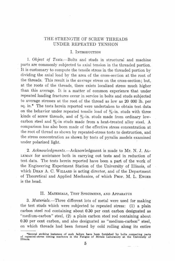
4. Test Specimens.-Figure 1 shows the specimens used in the testsunder repeated tensile load. Figure 1 (a) shows the specimen used fordetermining the endurance limit* of the material in the test studs.
*Endurance limit (or fatigue limit) is that stress below which fracture will not occur underan indefinitely large number of cycles of stress. In this series of tests the endurance limit de-termined is for stress ranging from nearly zero to a maximum tension. The endurance limitfor this range is probably about 50 per cent greater than the endurance limit for cycles ofstress ranging from a maximum tension to a compression of equal magnitude. The range ofstress from zero to maximum tension was chosen as the range of stress most representative of
the stress bolts and studs receive in service.
U.S. •landard and Whitworth Die-Cut Threads(b)

THE STRENGTH OF SCREW THREADS UNDER REPEATED TENSION
FlS. S2•anSard W12/11w4R0-1Fia. 2. U. S. STANDARD AND WHITWORTH SCREW THREADS
Figure 1 (b) shows the specimen used to determine the endurance limitof test specimens (%-in. studs) made from medium-carbon steel andfrom heat-treated nickel steel (S.A.E. 2320). Figure 1 (c) shows thespecimen used to determine the endurance limit of the studs withrolled threads.
The test specimens made from medium-carbon steel and from heat-treated nickel steel were threaded with a'sharp die. For each metalone set of specimens was threaded with a U. S. Standard %-in. die,and a second set of specimens with a Whitworth %-in. die. Figure 2shows the nominal shape of thread for the two dies. It is to be notedthat the absolutely sharp re-entrant corners called for in the U. S.Standard thread cannot be formed, and that there is always somerounding off of corners, although not so much as is found in the Whit-worth thread. The stud specimens (Fig. 3(b) and 3(c)) were fittedwith nuts as shown. The specimens with die-cut threads (U. S.Standard and Whitworth) then had only one or two threads carryingthe maximum tensile stress on the stud, while the rolled-thread studs,which were furnished threaded throughout their whole length, hada long threaded portion carrying the maximum tensile stress. R. R.Moore has shown (and H. F. Moore has checked his results by furthertests) that a single groove, shaped like a screw thread, is more effec-tive in reducing fatigue strength than is a long threaded portion of astud.* A direct comparison of fatigue strength between the studs withrolled threads and the studs with die-cut threads may not, therefore,be quite fair to the die-cut threads.
5. Testing Machine for Repeated Tension Tests.-Figure 3 showsthe repeated-tension testing machine used in the fatigue tests of teststuds. This machine was designed in the Fatigue of Metals Labora-
*See Reference No. 1 in the Selected List of References at the end of this bulletin.

ILLINOIS ENGINEERING EXPERIMENT STATION
Fil. 3. TESTING MACHINE FOR REPEATED TENSION TESTS(Courtesy of J. B. Hayes, Inc., Urbana, Ill.)
tory of the University of Illinois.* The variable-throw cam C worksthe lever A which, in turn, applies tension to the specimen S which issupported on carefully centered balls. The pull on the specimen istransmitted to the elastic ring E, which is fastened to the frameworkof the machine by means of a long vertical screw. The sidewise con-traction of the elastic ring E is a measure of the tensile force applied
*Since the completion of the tests herein described the machine has been materially modi-fied by Mr. G. N. Krouse so that tests under reversal of stress can be made in it as wellas tests under repeated tension.

THE STRENGTH OF SCREW THREADS UNDER REPEATED TENSION 9
to the specimen, and this sidewise contraction between the points PPis measured by means of a micrometer dial gage M. The elastic ring issimilar to those used for calibrating testing machines. The range ofstress to which the specimen S is subjected can be regulated by meansof the long vertical screw and the nuts at the top cross bar. When aspecimen breaks the lower fragment of the specimen and the socketholding it drop, closing an electric circuit, and operating a circuitbreaker, stopping the motor which drives the machine. The machineoperates at a speed of 1000 r.p.m., has a capacity of 2000 lb. maximumload, and is fitted with a revolution counter to indicate the number ofcycles of stress.
The procedure in carrying out a test is as follows: With the speci-men properly centered, the load required to produce the (nominal)stress desired is calculated; then, from the calibration curve furnishedwith each elastic ring, the lateral contraction of the elastic ring cor-responding to this load is determined; the variable-throw cam C andthe nuts at the upper end of the long vertical screw are then adjusteduntil, during one revolution of the cam, the load on the specimen variesfrom nearly zero to the desired maximum.
III. TEST DATA AND RESULTS
6. Test Procedure to Determine Endurance Limit.-The endurancelimit is first estimated for the metal. For repeated stress ranging fromnearly zero to a maximum tension this may be estimated at 75 percent of the tensile strength, as determined by a test of specimens in anordinary "static" testing machine. A specimen (like that shown inFig. 1 (a)) is then placed in the repeated-tension machine and thethrow of the cam and the position of the upper nuts adjusted until arevolution of the cam causes a range of stress of from nearly zero to atensile stress (say) 15 per cent above the estimated endurance limit.Then the machine is started, and, for the first hour or two, is stopped atfrequent intervals to allow taking up any slack that may be necessarydue to adjustments of the specimen to the sockets into which it isscrewed. When the specimen shows no further need of adjustmentthe machine is allowed to run until the specimen breaks. The rangeof stress and the number of cycles of stress required for fracture arethen recorded, and another specimen put in the machine, the throw ofthe cam being adjusted so that the range of stress is from nearly zeroto a slightly lower maximum value than was used for the first speci-

ILLINOIS ENGINEERING EXPERIMENT STATION
'I.
(4)
N.
1::
Fia. 4. S-N DIAGRAMS FOR TEST STUDS OF MEDIUM-CARBON STEEL-U. S. STANDARD AND WHITWORTH SCREW THREADS
IN
/04 10. 306 10o /08Number of Cycles of Stress for Fracture
FIG. 5. S-N DIAGRAMS FOR TEST STUDS OF MEDIUM-CARBON STEE'L-ROLLED THREADS
men. This process is repeated until a specimen withstands a givennumber of cycles of stress without fracture (if feasible, 10 000 000cycles for steel).
A diagram is then plotted with stresses as ordinates and number ofcycles of stress for fracture as abscissas (abscissas plotted to a log.scale). Such a diagram is known as a S-N diagram, and the stress atwhich this diagram becomes horizontal is taken as the endurance limit.
I

THE STRENGTH OF SCREW THREADS UNDER REPEATED TENSION 11
90000
80000
N
S70000
K
S60000
I -o 0000
40000
,' 30000
eo 000
/0000/O"v /0.? 10of t0/00'
Number of C'c/es of Stress for Fracture
Fio. 6. S-N DIAGRAMS FOR TEST STUDS OF HEAT-TREATED NICKEL STEEl-U. S. STANDARD AND WHITWORTH SCREW THREADS
7. S-N Diagrams of Fatigue Tests and Tabulated Results.-Fig-ures 4, 5, and 6 show the S-N diagrams for the fatigue tests made,and Table 1 gives the endurance limits determined for the differentmetals and different threads. In Table 1 are also given the resultsof static tests for tensile strength of the different metals.
IV. DISCUSSION OF RESULTS
8. "Stress Concentration" in Screw Threads.-Before taking up thediscussion of the quantitative results of the fatigue tests, it seemsdesirable to consider the general problem of "stress concentration," orperhaps a better term would be "localized stress intensification."
_ _Mefal of Sfuo6l
,S ' ([.g /a
10- A^( .- b---- -
__ I i I I 1 1 1 _ _ _ _
ILLINOIS ENGINEERING EXPERIMENT STATION
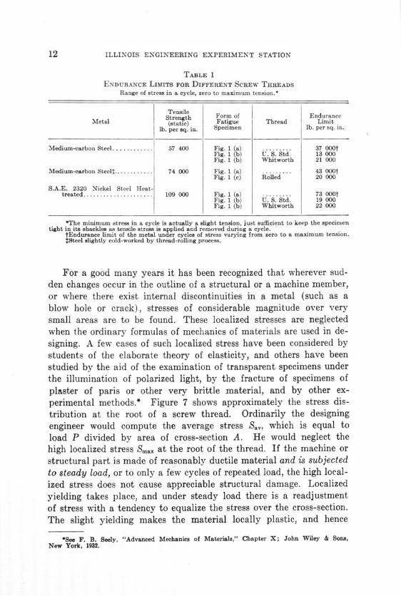
TABLE 1ENDURANCE LIMITS FOR DIFFERENT SCREW THREADS
Range of stress in a cycle, zero to maximum tension.*
TensileStrength Form of Endurance
Metal (static) Fatigue Thread Limitlb. per sq. in. Specimen lb. per sq. in.
Medium-carbon Steel ............ 57 400 Fig. 1 (a) ......... 37 000tFig. 1 (b) U. S. Std. 13 000Fig. 1 (b) Whitworth 21 000
Medium-carbon Steel .............. 74 000 Fig. 1 (a) ......... 43 000tFig. 1 (c) Rolled 20 000
S.A.E. 2320 Nickel Steel Heat-treated..................... 109 000 Fig. 1 (a) ......... 73 000t
Fig. 1 (b) U. S. Std. 19 000Fig. 1 (b) Whitworth 22 000
*The minimum stress in a cycle is actually a slight tension, just sufficient to keep the specimentight in its shackles as tensile stress is applied and removed during a cycle.
tEndurance limit of the metal under cycles of stress varying from zero to a maximum tension.$Steel slightly cold-worked by thread-rolling process.
For a good many years it has been recognized that wherever sud-den changes occur in the outline of a structural or a machine member,or where there exist internal discontinuities in a metal (such as ablow hole or crack), stresses of considerable magnitude over verysmall areas are to be found. These localized stresses are neglectedwhen the ordinary formulas of mechanics of materials are used in de-signing. A few cases of such localized stress have been considered bystudents of the elaborate theory of elasticity, and others have beenstudied by the aid of the examination of transparent specimens underthe illumination of polarized light, by the fracture of specimens ofplaster of paris or other very brittle material, and by other ex-perimental methods.* Figure 7 shows approximately the stress dis-tribution at the root of a screw thread. Ordinarily the designingengineer would compute the average stress Say, which is equal toload P divided by area of cross-section A. He would neglect thehigh localized stress Smax at the root of the thread. If the machine orstructural part is made of reasonably ductile material and is subjectedto steady load, or to only a few cycles of repeated load, the high local-ized stress does not cause appreciable structural damage. Localizedyielding takes place, and under steady load there is a readjustmentof stress with a tendency to equalize the stress over the cross-section.The slight yielding makes the material locally plastic, and hence
*See F. B. Seely, "Advanced Mechanics of Materials," Chapter X; John Wiley & Sons,New York, 1932.

THE STRENGTH OF SCREW THREADS UNDER REPEATED TENSION
FIG. 7. STRESS DISTRIBUTION AT ROOT OF THREAD
renders the theory of elasticity inapplicable for accurate determinationof stress, because that theory assumes perfect elasticity of material.Plastic yielding ("passing the elastic limit" as it is rather looselytermed) causes appreciable structural damage under static load onlyafter a considerable volume of material is affected.
Under many cycles of repeated load the case is quite different. Atthe point of localized stress plastic flow occurs over a minute area,and the metal in that minute area is strengthened and embrittled bycold work. As cycles of stress are repeated this metal graduallychanges its physical properties, not through "crystallization" but bythe gradual sliding over each other of layers of metal within crystals.If this sliding is continued for a sufficient number of cycles of stress,extremely minute cracks open up and spread. This spreading fractureconstitutes fatigue failure, and, while localized stress intensificationis not very apt to cause structural damage under a static load, it isvery likely to cause fracture by a spreading crack under a repeatedload of sufficient magnitude.
Applying this discussion to the screw thread it can be seen thatunder a single static load minute rings of metal at the roots of thethread will suffer plastic deformation. This deformation will be verysmall and will not appreciably affect the serviceability of the bolt. If,however, the bolt is subjected to repeated stress there is danger thatat some point of localized overstressing a crack will start and spreadto fracture.
9. Elastic Limit and Endurance Limit.-From the foregoing dis-cussion it may be thought that the limiting stress under repeatedloading would be the "true" elastic limit of a metal. When the struc-ture of metals is studied it is found that the ordinary metals of con-struction are made up of crystalline grains. X-ray crystallography

ILLINOIS ENGINEERING EXPERIMENT STATION
indicates that in each one of these crystalline grains the atoms arearranged in a regular geometrical pattern with a definite plane alongwhich slip can take place easily. It would be necessary, then, indetermining the "true" elastic limit, to determine the component ofstress along the slip planes of the most unfavorably oriented crystal.Inasmuch as thousands of crystals without any clear system of ori-entation are present in the ring of metal at the root of the thread,this is seen to be impracticable. The elastic limit as determined in thelaboratory is a stress at which an arbitrarily determined amount ofplastic action takes place in a test specimen taken as a whole.
A more practical index of strength under repeated stress is the en-durance limit (or fatigue limit). This is the limiting stress below whichno fracture of specimen occurs even after an -indefinitely large numberof cycles of stress have been applied.* Even in a specimen free fromgrooves, screw threads, or other external causes of stress concentra-tion ("stress raisers" as Dr. H. W. Gillett calls them) the endurancelimit is well below the static tensile strength, and shows no well de-fined relation to the elastic limit as determined in the laboratory. Theexplanation of this difference between endurance limit and tensilestrength is that the structure of the metal itself is non-homogeneousand stress concentration occurs between crystal and crystal, and prob-ably within crystals.
10. Determination of Stress-concentration Factors.-The methodsof the mathematical theory of elasticity have not, so far as the writersknow, been successfully applied to determine stress concentration atthe root of screw threads. The determination of stress concentrationin screw threads by photo-elastic methods has been given some studyby Mr. Stanley G. Hall, and his work is recorded in Bulletin No. 245,Engineering Experiment Station, University of Illinois. The photo-elastic method, in which polarized light is passed through specimens oftransparent material, is an attempt to use optical and mechanicalmethods to solve problems of stress concentration. The material testedmust be transparent, and bakelite, pyralin, or celluloid are the ma-terials commonly used for specimens. The properties of the materialsare not of interest to the user of polarized light except that theremust be elastic strength enough to permit the application of loadsand deformations which can be measured. The stress concentrations
*See Proceedings, Am. Soc. for Testing Materials, Vol. 30, Part I, pp. 272-284 (1930).This article by Professor J. B. Kommers, a part of the 1930 report of the Research Committeeon Fatigue of Metals, discusses variation of endurance limit with range of stress.

THE STRENGTH OF SCREW THREADS UNDER REPEATED TENSION 15
TABLE 2STRESS-CONCENTRATION FACTORS FOR SCREW THREADS AS GIVEN BY
FATIGUE TESTS AND BY PHOTO-ELASTIC TESTS
Stress-concentration Factor
Thread MetalBy Fatigue By Photo-
Test* elastic Testt
U. S. Std.......... Medium-carbon Steel .................. 2.845.62
S.A.E. 2320 Nickel Steel Heat-treated.... 3.85
Whitworth........ Medium-carbon Steel. ................. 1.763.86
S.A.E. 2320 Nickel Steel Heat-treated.... 3.32
Rolled............ Medium-carbon Steel .................. 2.151
*Stress-concentration factor by fatigue test is determined by dividing endurance limit of metal(tests of specimen shown in Fig. 1 (a)) by endurance limit of specimen with critical section at threadedportion (as shown by Fig. 1 (b) or Fig. 1 (c) ).
tTests on pyralin specimens viewed by polarised light,-see Bulletin 245 of the EngineeringExperiment Station, University of Illinois.
tMetal slightly cold-worked by thread-rolling process.
determined by such tests, may, then, be classed as theoretical stressconcentrations.
From the fatigue tests of specimens of the same metal with andwithout screw threads at the critical section an effective stress con-centration may be determined by dividing the endurance limit of themetal as determined by fatigue tests of specimens like those shown inFig. 1 (a) by the endurance limit of specimens like those shown inFig. 1 (b) or 1 (c).
Table 2 gives the results of Mr. Hall's work with photo-elasticmethods and also the effective stress-concentration factors as deter-mined from the data given in this bulletin.
V. CONCLUSIONS
11. Summary of Conclusions.-
(1) The stress-concentration factor for a screw thread is definedas the ratio of maximum stress, which is at the root of the thread, tothe average stress over the minimum area of cross section of thethread. This factor may be determined directly by photo-elastictests. The effective stress concentration factor may be defined as theratio of the endurance limit of the metal itself to the endurance limitof specimens which fail in the screw threads. The tests herein re-ported, taken in connection with photo-elastic tests previously re-

ILLINOIS ENGINEERING EXPERIMENT STATION
ported, indicate that the stress-concentration factor determined byphoto-elastic tests is larger than the effective stress-concentrationfactor determined by fatigue tests. In other words, determination ofstress concentration in screw threads by photo-elastic tests gave results"on the safe side" as compared with those given by fatigue tests.
(2) Both photo-elastic tests and fatigue tests of %-in. studs gavehigher stress-concentration factors for die-cut U. S. Standard threadsthan for die-cut Whitworth threads.
(3) Rolled threads on a medium-carbon steel rod % in. in diametergave effective stress-concentration factors intermediate between thosefor die-cut Whitworth threads and those for die-cut U. S. Standardthreads, but this superiority over the U. S. Standard die-cut threadsmay be explained by the fact that the rolled-thread specimens werethreaded for the full length, while the die-cut specimens were threadedat the ends only.
(4) For both U. S. Standard threads and Whitworth threadshigher effective stress-concentration factors were found for heat-treated nickel steel studs than for medium-carbon steel studs. Thisindicates that the heat-treated nickel steel is more sensitive to stressconcentration than is the medium-carbon steel, and that a smallerproportion of the tensile strength of the material is available in heat-treated nickel steel bolts and studs subjected to repeated stress thanis the case with ordinary structural steel bolts and studs.
(5) For heat-treated nickel steel studs with %-in. U. S. Standardthreads an effective stress-concentration factor of 3.85 was observed;for medium-carbon steel this factor was 2.84. These figures suggest thatfor bolts or studs subjected to repeated tensile stress a safe estimate ofthe stress at the root of the thread would be not the nominal valueP 3P 4P- but for ordinary structural steel, and -- for heat-treatedA A Aalloy steels commonly carried in stock, where P is the load in poundsand A is the area at the root of the thread in square inches.

APPENDIX
LIST OF SELECTED REFERENCES
1. MOORE, R. R. "Effect of Grooves, Threads, and Corrosion upon the Fatigueof Metals," Proc. Am. Soc. for Testing Materials, Vol. 26, Part II. p. 255(1926)
2. PULSIFER, H. B. "The Physical Properties of Fine Bolts," Trans. Am. Soc. forSteel Treating, Vol. 18, 1930, p. 273. This paper deals mainly with thestatic strength properties of bolts.
3. SLAUGHTER, E. M. "Tests on Threaded Sections," Metals Progress, Vol. 23,No. 3, p. 18 (March 1933). See also discussion by Karl Schmimz inMetals Progress, Vol. 24, No. 5, p. 50, (Nov. 1933), This paper and thediscussion deal with static strength properties only.
4. MANVILLE MACHINE CO., Waterbury, Conn. "The Art of Screw Thread Roll-ing," Trade Publication, 1913.
5. MOORE, H. F., and KOMMERS, J. B. "The Fatigue of Metals," Chapter VIII.McGraw-Hill Book Co., New York, 1927.
6. PETERSON, R. E. "Stress Concentration and Fatigue," in Report of ResearchCommittee on Fatigue of Metals, Proc. Am. Soc. for Testing Materials,Vol. 30, Part I. p. 298, 1930.
7. THUM and STAEDEL, "On the Endurance Strength of Screws and the Influenceof their Shape" (Ueber die Dauerfestigkeit von Schrauben in ihrer Beein-flussung durch Formgebung) Maschinenbau, Vol. 11, June 2, 1932, p. 230.Abstract of above (in English) in Metals and Alloys, Sept. 1933, p. Ma 286.
8. LEA, F. C. "The Strength of Materials as Affected by Discontinuities andSurface Conditions," (British) Journal of Glass Technology, Vol. 16, June1932, p. 182.
9. HALL, STANLEY G. "Determination of Stress Concentration in Screw Threadsby the Photo-elastic Method," Bulletin 245, Engineering Experiment Sta-tion, University of Illinois.
10. WIEGAND, H. "Fatigue Properties of Bolts and Nuts in Dependence on theShape of the Nut" (Die Dauerfestigkeit der Schraube in Abhaengigkeit vonder Mutterform) Schriften der Hessichen Hochschulen, 1933, No. 2, p. 67.Abstract of above (in English) in Metals and Alloys, May, 1934.


RECENT PUBLICATIONS OFTHE ENGINEERING EXPERIMENT STATIONt
Bulletin No. 217. Washability Tests of Illinois Coals, by Alfred C. Callen andDavid R. Mitchell. 1930. Sixty cents.
Bulletin No. 218. The Friability of Illinois Coals, by Cloyde M. Smith. 1930.Fifteen cents.
Bulletin No. 219. Treatment of Water for Ice Manufacture, by Dana Burks, Jr.1930. Sixty cents.
Bulletin No. 220. Tests of a Mikado-Type Locomotive Equipped with Nichol-son Thermic Syphons, by Edward C. Schmidt, Everett G. Young, and Herman J.Schrader. 1930. Fifty-five cents.
Bulletin No. 221. An Investigation of Core Oils, by Carl H. Casberg and Carl E.Schubert. 1931. Fifteen cents.
Bulletin No. 222. Flow of Liquids in Pipes of Circular and Annular Cross-Sections, by Alonzo P. Kratz, Horace J. Macintire, and Richard E. Gould. 1931.Fifteen cents.
Bulletin No. 223. Investigation of Various Factors Affecting the Heating ofRooms with Direct Steam Radiators, by Arthur C. Willard, Alonzo P. Kratz, MauriceK. Fahnestock, and Seichi Konzo. 1931. Fifty-five cents.
Bulletin No. 224. The Effect of Smelter Atmospheres on the Quality of Enamelsfor Sheet Steel, by Andrew I. Andrews and Emanuel A. Hertzell. 1931. Ten cents.
Bulletin No. 225. The Microstructure of Some Porcelain Glazes, by Clyde L.Thompson. 1931. Fifteen cents.
Bulletin No. 226. Laboratory Tests of Reinforced Concrete Arches with Decks,by Wilbur M. Wilson. 1931. Fifty cents.
Bulletin No. 227. The Effect of Smelter Atmospheres on the Quality of DryProcess Enamels for Cast Iron, by A. I. Andrews and H. W. Alexander. 1931.Ten cents.
Circular No. 21. Tests of Welds, by Wilbur M. Wilson. 1931. Twenty cents.Bulletin No. 228. The Corrosion of Power Plant Equipment by Flue Gases,
by Henry Fraser Johnstone. 1931. Sixty-five cents.Bulletin No. 229. The Effect of Thermal Shock on Clay Bodies, by William R.
Morgan. 1931. Twenty cents.Bulletin No. 230. Humidification for Residences, by Alonzo P. Kratz. 1931.
Twenty cents.Bulletin No. 231. Accidents from Hand and Mechanical Loading in Some Illinois
Coal Mines, by Alfred C. Callen and Cloyde M. Smith. 1931. Twenty-five cents.Bulletin No. 232. Run-Off Investigations in Central Illinois, by George W.
Pickels. 1931. Seventy cents.Bulletin No. 233. An Investigation of the Properties of Feldspars, by Cullen W.
Parmelee and Thomas N. McVay. 1931. Thirty cents.Bulletin No. 234. Movement of Piers during the Construction of Multiple-Span
Reinforced Concrete Arch Bridges, by Wilbur M. Wilson. 1931. Twenty cents.Reprint No. 1. Steam Condensation an Inverse Index of Heating Effect, by
Alonzo P. Kratz and Maurice K. Fahnestock. 1931. Ten cents.Bulletin No. 235. An Investigation of the Suitability of Soy Bean Oil for Core
Oil, by Carl H. Casberg and Carl E. Schubert. 1931. Fifteen cents.Bulletin No. 236. The Electrolytic Reduction of Ketones, by Sherlock Swann,
Jr. 1931. Ten cents.Bulletin No. 237. Tests of Plain and Reinforced Concrete Made with Haydite
Aggregates, by Frank E. Richart and Vernon P. Jensen. 1931. Forty-five cents.Bulletin No. 238. The Catalytic Partial Oxidation of Ethyl Alcohol, by Donald
B. Keyes and Robert D. Snow. 1931. Twenty cents.Bulletin No. 239. Tests of Joints in Wide Plates, by Wilbur M. Wilson, James
Mather, and Charles 0. Harris. 1931. Forty cents.
ftCopies of the complete list of publications can be obtained without charge by addressing theEngineering Experiment Station, Urbana, Ill.

ILLINOIS ENGINEERING EXPERIMENT STATION
"Bulltihn ao. 240. The Flow of Air through Circular Orifices in Thin Plates, bhJoseph A. Polson and Joseph G. Lowther. 1932. Twenty-five cents.
*Bulletin No. 241. Strength of Light I Beams, by Milo S. Ketchum and Jasper 0.Draffin. 1932. Twenty-five cents.
*Bulletin No. 242. Bearing Value of Pivots for Scales, by Wilbur M. Wilson,Roy L. Moore, and Frank P. Thomas. 1932. Thirty cents.
*Bulletin No. 243. The Creep of Lead and Lead Alloys Used for Cable Sheathing,by Herbert F. Moore and Norville J. Alleman. 1932. Fifteen cents.
*Bulletin No. 244. A Study of Stresses in Car Axles under Service Conditions,by Herbert F. Moore, Nereus H. Roy, and Bernard B. Betty. 1932. Forty cents.
*Bulletin No. 245. Determination of Stress Concentration in Screw Threads bythe Photo-Elastic Method, by Stanley G. Hall. 1932. Ten cents.
Bulletin No. 246. Investigation of Warm-Air Furnaces and Heating Systems,Part V, by Arthur C. Willard, Alonzo P. Kratz, and Seichi Konzo. 1932. Eighty cents.
*Bulletin No. 247. An Experimental Investigation of the Friction of ScrewThreads, by Clarence W. Ham and David G. Ryan. 1932. Thirty-five cents.
*Bulletin No. 248. A Study of a Group of Typical Spinels, by Cullen W. Parmelee,Alfred E. Badger, and George A. Ballam. 1932. Thirty cents.
*Bulletin A o. 249. The Effects on Mine Ventilation of Shaft-Bottom Vanes andImprovements in Air Courses, by Cloyde M. Smith. 1932. Twenty-five cents.
*Bulletin No. 250. A Test of the Durability of Signal-Relay Contacts, by EverettE. King.' 1932. Ten cents.
*Bulletin No. 251. Strength and Stability of Concrete Masonry Walls, by FrankE. Richart, Robert B. B. Moorman, and Paul M. Woodworth. 1932. Twenty cents.
*Bulletin No. 252. The Catalytic Partial Oxidation of Ethyl Alcohol in the VaporPhase. The Use of a Liquid Salt Bath for Temperature Control, by Donald B.Keyes and William Lawrence Faith. 1932. Ten cents.
Bulletin No. 253. Treatment of Water for Ice Manufacture, Part II, by DanaBurks, Jr. 1933. Forty-five cents.
Bulletin No. 254. The Production of Manufactured Ice at Low Brine Temper-ature, by Dana Burks, Jr. 1933. Seventy cents.
Bulletin No. 255. The Strength of Thin Cylindrical Shells as Columns, byWilbur M. Wilson and Nathan M. Newark. 1933. Fifty cents.
Bulletin No. 256. A Study of the Locomotive Front End, Including Tests of aFront-End Model, by Everett G. Young. 1933. One dollar.
*Bulletin No. 257. The Friction of Railway Brake Shoes, Its Variation withSpeed, Shoe Pressure and Wheel Material, by Edward C. Schmidt and Herman J.Schrader. 1933. One dollar.
*Bulletin No. 258. The Possible Production of Low Ash and Sulphur Coal inIllinois as Shown by Float-and-Sink Tests, by D. R. Mitchell. 1933. Fifty cents.
*Budletin No. 259. Oscillations Due to Ionization in Dielectrics and Methods ofTheir Detection and Measurement, by J. Tykocinski Tykociner, Hugh A. Brown,and Ellery Burton Paine. 1933. Sixty-five cents.
*Bidletin No. 260. Investigation of Cable Ionization Characteristics with Dis-charge Detection Bridge, by Hugh A. Brown, J. Tykocinski Tykociner, and ElleryBurton Paine. 1933. Fifty cents.
*Bulletin No. 261. The Cause and Prevention of Calcium Sulphate Scale inSteam Boilers, by Frederick G. Straub. 1933. Eighty-five cents.
*Bulletin No. 262. Flame Temperatures in an Internal Combustion Engineýleasured by Spectral Line Reversal, by Albert E. Hershey and Robert F. Paton.1933. Fifty-five cents.
Reprint No. 2. Progress in the Removal of Sulphur Compounds from WasteGases, by Henry Fraser Johnstone. 1933. Twenty cents.
*Bultetin No. 263. The Bearing Value of Rollers, by Wilbur M. Wilson. 1933.Forty cents.
*Circular No. 22. Condensation of Moisture in Flues, by William R. Morgan.1933. Thirty cents.
*Bulletin No. 264. The Strength of Screw Threads under Repeated Tension, byHerbert F. Moore and Proctor E. Henwood. 1933. Twenty-five cents.
*A limited number of copies of bulletins starred are available for free distribution.


