47
CS48711-1/31 Illinois Institute of Technology CS487 Software Engineering OOA with UML David Lash
| Date post: | 01-Jan-2016 |
| Category: |
Documents |
| Upload: | lance-kent |
| View: | 14 times |
| Download: | 1 times |

CS48711-1/31
Illinois Institute of Technology
CS487
Software Engineering
OOA with UML
David Lash
CS48711-2/31
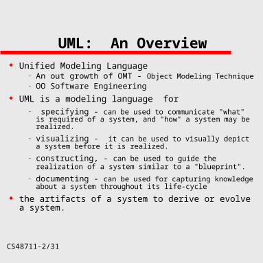
UML: An Overview Unified Modeling Language
– An out growth of OMT - Object Modeling Technique– OO Software Engineering
UML is a modeling language for– specifying - can be used to communicate "what" is
required of a system, and "how" a system may be realized.
– visualizing - it can be used to visually depict a system before it is realized.
– constructing, - can be used to guide the realization of a system similar to a "blueprint".
– documenting - can be used for capturing knowledge about a system throughout its life-cycle
the artifacts of a system to derive or evolve a system.

CS48711-3/31
UML: An Overview
The UML is not:
A visual programming language, but a visual modeling language.
A tool or repository specification, but a modeling language specification.
A process, but enables processes.
Fundamentally, the UML is concerned with capturing, communicating, and levering knowledge
CS48711-4/31
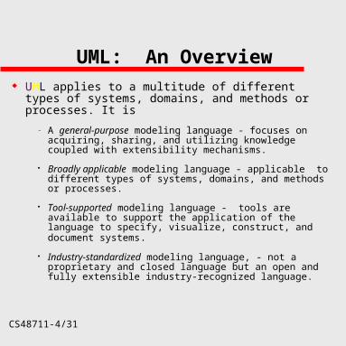
UML: An Overview UML applies to a multitude of different types of
systems, domains, and methods or processes. It is
– A general-purpose modeling language - focuses on acquiring, sharing, and utilizing knowledge coupled with extensibility mechanisms.
Broadly applicable modeling language - applicable to different types of systems, domains, and methods or processes.
Tool-supported modeling language - tools are available to support the application of the language to specify, visualize, construct, and document systems.
Industry-standardized modeling language, - not a proprietary and closed language but an open and fully extensible industry-recognized language.

CS48711-5/31
UML: Views
Unified Modeling Language supports 5 views to use diagrams to describe the system from different perspectives
– User Model View - Use-case modeling approach to representation of the end-user’s perspective.
– Structured Model View - Data and functionality viewed from inside the system (classes, objects & relationships)
– Behavior View - models the behaviours and interactions of various structures
– Implementation model view - the structural and behavior aspects o f the system
– Environment Model View - structural and behaviour aspects of the environment

CS48711-6/31
UML: Views
Unified Modeling Language supports 5 views to use diagrams to describe the system from different perspectives
– User Model View - Use-case modeling approach to representation of the end-user’s perspective.
– Structured Model View - Data and functionality viewed from inside the system (classes, objects & relationships)
– Behavior View - models the behaviours and interactions of various structures
– Implementation model view - the structural and behavior aspects of the system
– Environment Model View - structural and behaviour aspects of the environment

CS48711-7/31
UML: Uses a variety of Diagrams
Use Case
– Show a set of use cases and actors and their relationships
Actors: entities that interact with the system
Class– Show a set of classes, interfaces and
collaborations and their relationships

CS48711-8/31
UML: Diagrams
Interaction – Sequence and collaboration– Show an interaction, consisting of a set of
objects and their relationships
Dependency– A relationship between two elements in which
a change to one element may affect or supply information needed by the other element.

CS48711-9/31
UML: Diagrams State
– Shows behavior a class or use case.– Different notation
Activity – Show the flow from activity to activity within
a system

CS48711-10/31
UML: Diagrams
Component– Show the organizations and dependencies
among a set of components (subsystem)
Deployment– Show the configuration of run-time processing
nodes and components that live on them

CS48711-11/31
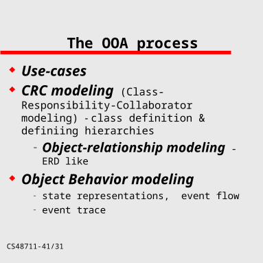
The OOA process
Use-cases CRC modeling (Class-Responsibility-
Collaborator modeling) - class definition & definiing hierarchies
Object-relationship modeling - ERD like Object Behaviour modeling
– state representations, event flow– event trace
CS48711-12/31
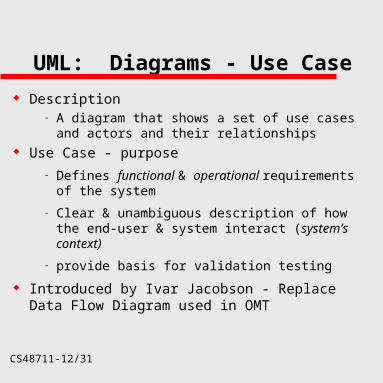
UML: Diagrams - Use Case
Description– A diagram that shows a set of use cases and
actors and their relationships Use Case - purpose
– Defines functional & operational requirements of the system
– Clear & unambiguous description of how the end-user & system interact (system’s context)
– provide basis for validation testing
Introduced by Ivar Jacobson - Replace Data Flow Diagram used in OMT

CS48711-13/31
Use Case: Terms Terms
– Actor An abstraction for entities outside a
system, subsystem, or class that interact directly with the system.
– Classifier A model element that describes
behavioral and structural features– Use Case
The specification of sequences of actions, including variant sequences and error sequences, that a system, subsystem, or class can perform by interacting with outside actors.

CS48711-14/31
UML: Diagrams
Use Case
– Show a set of use cases and actors and their relationships
Actors: entities that interact with the system
Example: Consider homesafe with actors:– homeowner, sensors, & monitoring &
response subsystem– Look only at homeowner for now

CS48711-15/31
Use Case: Actor Relationships
Salesperson
Sales Manager Sales Clerk
CS48711-16/31
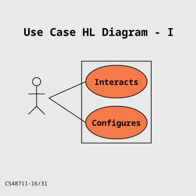
Use Case HL Diagram - I
Configures
Interacts
CS48711-17/31
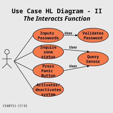
Use Case HL Diagram - IIThe Interacts Function
Inputs Passwords
Inquirezone
status
PressPanic Button
Activates/deactivates
system
ValidatesPassword
Uses
QuerySensor
Uses
Uses

CS48711-18/31
Use Case: Symbols
Actor
system boundary
Use Case
generalizationextend / includeCommunication
CS48711-19/31
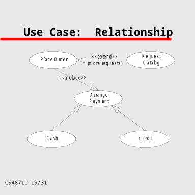
Use Case: Relationship
Place Order
ArrangePayment
RequestCatalog
<<extend>>(more requests)
Cash Credit
<<include>>
CS48711-20/31
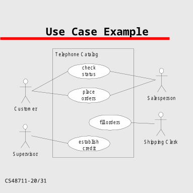
Use Case Example
Customer
Supervisor
Shipping Clerk
Salesperson
Telephone Catalog
checkstatus
placeorders
fill orders
establishcredit
CS48711-21/31
Hints and Tips
A well-structured Use Case diagram:– Focus on communicating one aspect of a
system’s static Use Case view– Contain only those use cases and actors that
are essential to understanding that aspect– Provide detail consistent with its level of
abstraction; you expose only those adornments that are essential to understanding
– Is not so minimalist as to misinform the reader about the semantics that are important
CS48711-22/31
Hints and Tips
When you draw a Use Case diagram– Give it a name that communicates its purpose– Lay out its elements to minimize lines that
cross– Organize its elements spatially so that
behaviors and roles that are semantically close are laid out physically close
– Use notes and color as visual cues to draw attention to important features of your diagram
– Try not to show too many kinds of relationships

CS48711-23/31
The OOA process
Use-cases CRC modeling (Class-Responsibility-
Collaborator modeling) - class definition & definiing hierarchies
– Object-relationship modeling - ERD like
Object Behavior modeling– state representations, event flow– event trace

CS48711-24/31
CRC modeling (Class-Responsibility-Collaborator
modeling) - class definition & defining hierarchies
A simple means for identifying and organizing classes
CS48711-25/31
Selecting Objects (review)
Already spoke about the Six characteristics that should be used on each potential object:
– Retained Information - information about it must be remembered
– Needed services - have a set of identifiable operations that can change attribute’s value
– Multiple Attributes - Are the attributes “major” and useful?
– Common Attributes - can define a set that apply to all occurrences of object
– Essential requirements - External entity in problem and produces information essential to solution
CS48711-26/31
Collaborations- Defining relatips between Classes
A Class can :– use its operations to manipulate its own attributes
or – collaborate with other classes if it cannot complete
its responsibilities by itself Review classes & determine relationship type:
– is-part-of relationship - All classes part of an aggregate class. Player_body is part of player, player_arms is part of player.
– has-knowledge-of relationship - when 1 class must acquire information from another. Control_panel object must determine if any sensors are open. determine_sensor_status relationship between them. Control_panel must work with sensor to get status.
– depends-upon relationship - 2 classes have a dependency that is not 1 of the 2 above -Player_head must always be connected to player-body. (yet they can exist w/o knowledge of eachother).
CS48711-27/31
UML: Create Class Diagram
Use the Class diagram to – Show a set of classes, interfaces and
collaborations and their relationships– Focuses on the the structure of the classes &
hierarchies
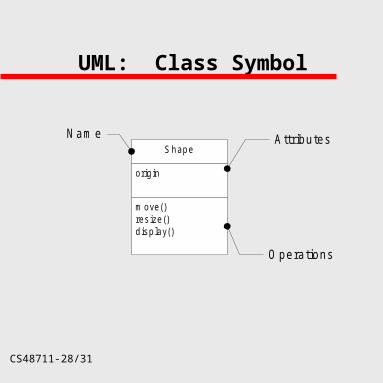
Components– Name– Attributes– Operations– Responsibilities
CS48711-28/31
UML: Class Symbol
origin
move()resize()display()
Shape
Nam e
Operations
Attributes

CS48711-29/31
UML: Class Diagram Chart Structure
Sensor
Attributes
Operatations
Entry Sensor Smoke Sensor Monitor Sensor
•After ID classes & objects, => determine structure. - Objects might be generalization/specialization structure. - Sensor is the generalization of the specialized entry, smoke & motion sensors
CS48711-30/31
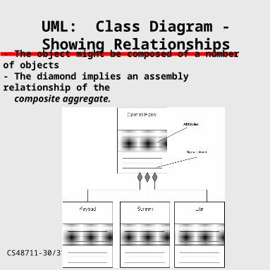
UML: Class Diagram - Showing Relationships
- The object might be composed of a number of objects- The diamond implies an assembly relationship of the
composite aggregate.
CS48711-31/31
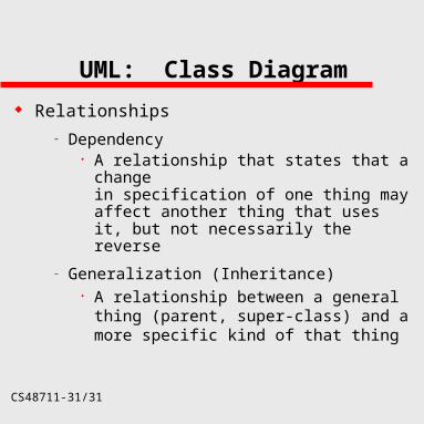
UML: Class Diagram
Relationships
– Dependency A relationship that states that a change
in specification of one thing may affect another thing that uses it, but not necessarily the reverse
– Generalization (Inheritance) A relationship between a general thing
(parent, super-class) and a more specific kind of that thing

CS48711-32/31
UML: Class Diagram
Relationships– Association
A structural relationship that specifies that objects of one thing are connected to objects of another
Characteristics– Name– Role– Multiplicity
– Aggregation Components that comprise the owning
object

CS48711-33/31
UML: Class Relationships
open()close()m ove()display()handleEvent()
W indow
C onsoleW indow D ialogBox C ontro l
Event
dependency
association
generalization
CS48711-34/31
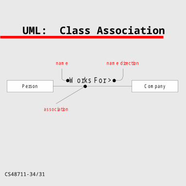
UML: Class Association
Person CompanyW orks For >
name name direction
association
CS48711-35/31
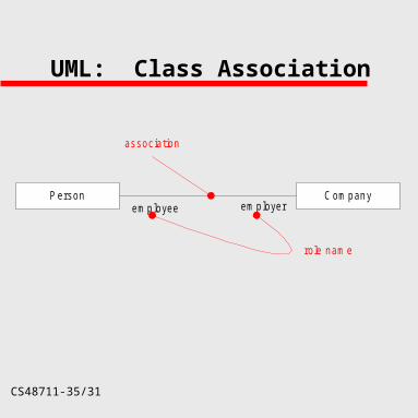
UML: Class Association
Person Company
association
employee employer
role name

CS48711-36/31
UML: Class Association
Person Company
association
employee employer
multiplicity
1..* *
Indicates many
CS48711-37/31
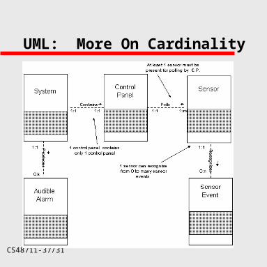
UML: More On Cardinality
CS48711-38/31
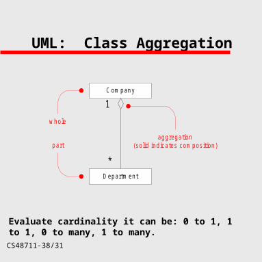
UML: Class Aggregation
Department
Company
whole
part
1
*
aggregation(solid indicates composition)
Evaluate cardinality it can be: 0 to 1, 1 to 1, 0 to many, 1 to many.

CS48711-39/31
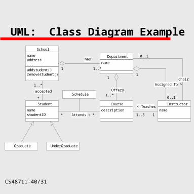
Identifying Classes
Develop an automated student registration system. The students registration system identify the School (i.e. Arts & Sciences, Engineering, Fine Arts, etc.) in which the student is registered. It also shall Identify the current classes offered by each department and the instructor for each class.
CS48711-40/31
UML: Class Diagram Example
nameaddress...
addstudent()removestudent()...
School
namestudentID
Student
1..*
*
Graduate UnderGraduate
name
Department
description
Course
name
Instructor
Offers
1
1..*
Attends >
< Teaches
has
1..*1
* * 1..3 1
Assigned To ^
Chair1
0..1
0..1Schedule
accepted
CS48711-41/31
The OOA process
Use-cases CRC modeling (Class-Responsibility-
Collaborator modeling) - class definition & definiing hierarchies
– Object-relationship modeling - ERD like
Object Behavior modeling– state representations, event flow– event trace
CS48711-42/31
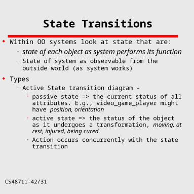
State Transitions
Within OO systems look at state that are:– state of each object as system performs its
function– State of system as observable from the outside world (as
system works)
Types– Active State transition diagram -
passive state => the current status of all attributes. E.g., video_game_player might have position, orientation
active state => the status of the object as it undergoes a transformation, moving, at rest, injured, being cured.
Action occurs concurrently with the state transition

CS48711-43/31
UML: Activity Diagram
CS48711-44/31
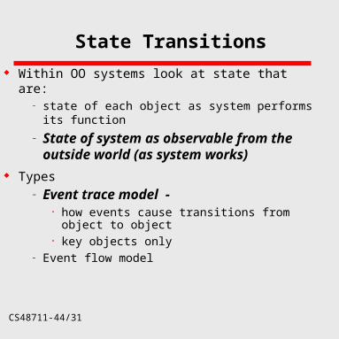
State Transitions
Within OO systems look at state that are:– state of each object as system performs its
function
– State of system as observable from the outside world (as system works)
Types– Event trace model -
how events cause transitions from object to object
key objects only– Event flow model
CS48711-45/31
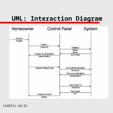
UML: Interaction Diagram
CS48711-46/31
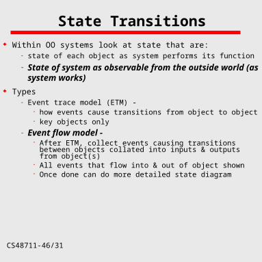
State Transitions
Within OO systems look at state that are:– state of each object as system performs its function
– State of system as observable from the outside world (as system works)
Types– Event trace model (ETM) -
how events cause transitions from object to object key objects only
– Event flow model - After ETM, collect events causing transitions between
objects collated into inputs & outputs from object(s) All events that flow into & out of object shown Once done can do more detailed state diagram
CS48711-47/31
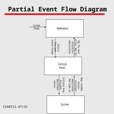
Partial Event Flow Diagram
Homeowner
ControlPanel
System
SystemReady
SelectsStay/aw
ay.Enters Passw
d
Rdy for next
action. Rdy for
activation/deactivation
Beep sounded.sensors
activated/deactivated.R
ed light on.
Initiates beep.Activate/
deactivatesensors


