Model CXT-IR Operator’s Installation and Instruction Manual Covers all Model CXT-IR Sensors September 30, 2013• Document 3822 • Revision 1.4 DETCON, Inc. 4055 Technology Forest Blvd, The Woodlands, Texas 77381 Ph.281.367.4100 / Fax 281.298.2868 www.detcon.com
Transcript
Need
Model CXT-IR
Operator’s Installation and Instruction ManualCovers all Model CXT-IR Sensors
2.5.1 Applying Power to the Unit ...................................................................................................142.6 Initial Start Up .............................................................................................................................................. 15
2.6.1 Combustible Gas Sensors ......................................................................................................152.6.2 Initial Operational Tests........................................................................................................162.6.3 Material Requirements ..........................................................................................................16
3.1.1 Normal Operation..................................................................................................................183.1.2 Calibration Mode...................................................................................................................183.1.3 Program Mode.......................................................................................................................183.1.4 Software Flowchart................................................................................................................19
3.2 Normal Operation......................................................................................................................................... 203.3 Calibration Mode.......................................................................................................................................... 20
3.3.1 AutoZero ................................................................................................................................203.3.2 AutoSpan................................................................................................................................213.3.3 Material Requirements: .........................................................................................................21
3.4 Program Mode.............................................................................................................................................. 233.4.1 Navigating Program Mode ....................................................................................................23
3.5 View Sensor Status....................................................................................................................................... 243.6 Set Gas Type ................................................................................................................................................ 243.7 Set AutoSpan Level...................................................................................................................................... 253.8 Set Gas Factor .............................................................................................................................................. 253.9 Bump Test .................................................................................................................................................... 263.10 Restore Defaults ........................................................................................................................................... 273.11 Set RF Channel............................................................................................................................................. 27
Model CXT-IR
Model CXT-IR Rev. 1.4 iv
3.11.1 Set Modbus™ ID....................................................................................................................273.12 Fault Diagnostic/Failsafe Feature .................................................................................................................28
5. Service and Maintenance ....................................................................................................................34
5.1 Calibration Frequency ..................................................................................................................................345.2 Visual Inspection ..........................................................................................................................................355.3 Condensation Prevention Packet ..................................................................................................................355.4 Replacement of the Batteries/Battery Pack...................................................................................................35
5.4.1 Low Battery Fault Indication.................................................................................................355.4.2 Units with 12V Smart Battery Pack .......................................................................................355.4.3 Units with Tri-C sized Lithium Battery Holder......................................................................35
5.5 Replacement of Plug-in Sensor.....................................................................................................................365.6 Replacement of ITM – Aluminum Junction Box..........................................................................................375.7 Replacement of ITM – Stainless Steel Mini Condulet .................................................................................37
Model CXT-IR Instruction Manual Rev. 1.4 Page 1 of 46
1. Introduction
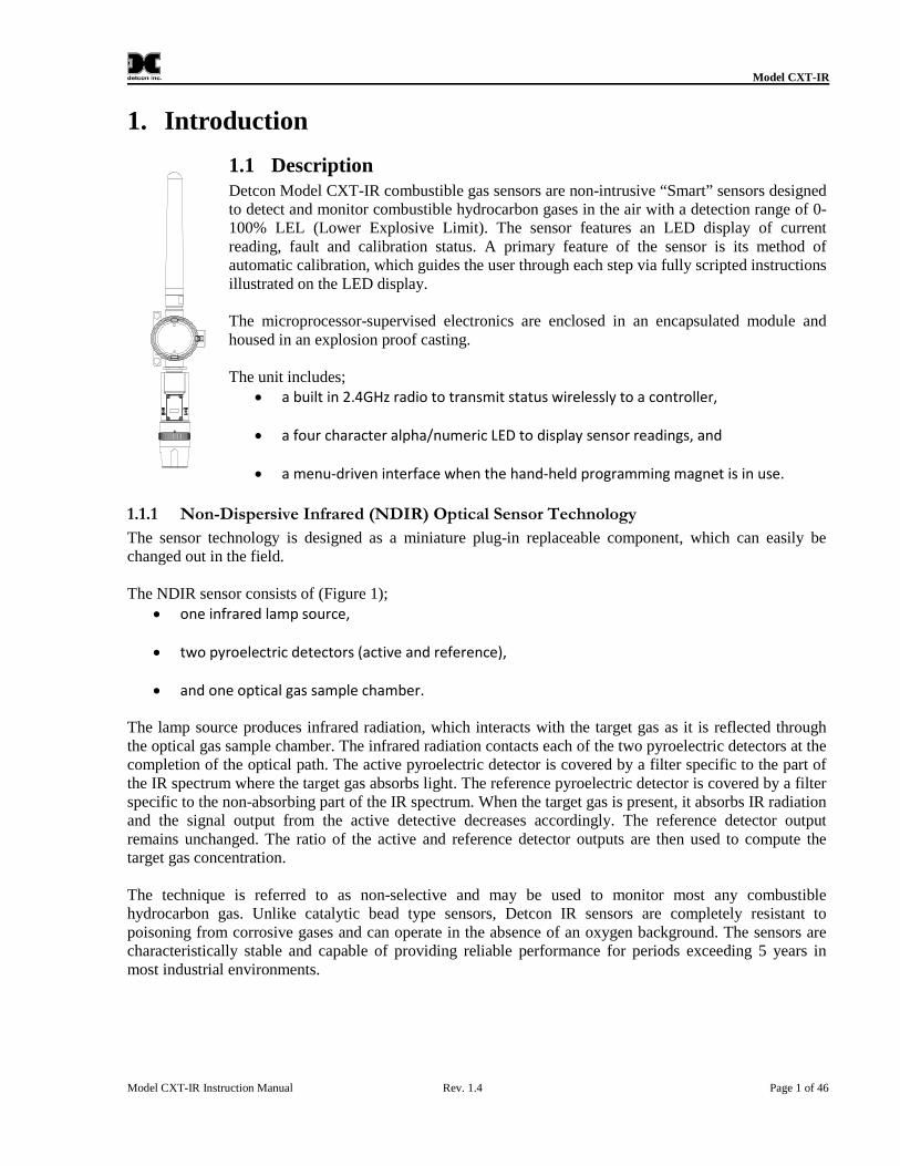
1.1 DescriptionDetcon Model CXT-IR combustible gas sensors are non-intrusive “Smart” sensors designedto detect and monitor combustible hydrocarbon gases in the air with a detection range of 0-100% LEL (Lower Explosive Limit). The sensor features an LED display of currentreading, fault and calibration status. A primary feature of the sensor is its method ofautomatic calibration, which guides the user through each step via fully scripted instructionsillustrated on the LED display.
The microprocessor-supervised electronics are enclosed in an encapsulated module andhoused in an explosion proof casting.
The unit includes; a built in 2.4GHz radio to transmit status wirelessly to a controller,
a four character alpha/numeric LED to display sensor readings, and
a menu-driven interface when the hand-held programming magnet is in use.
The sensor technology is designed as a miniature plug-in replaceable component, which can easily bechanged out in the field.
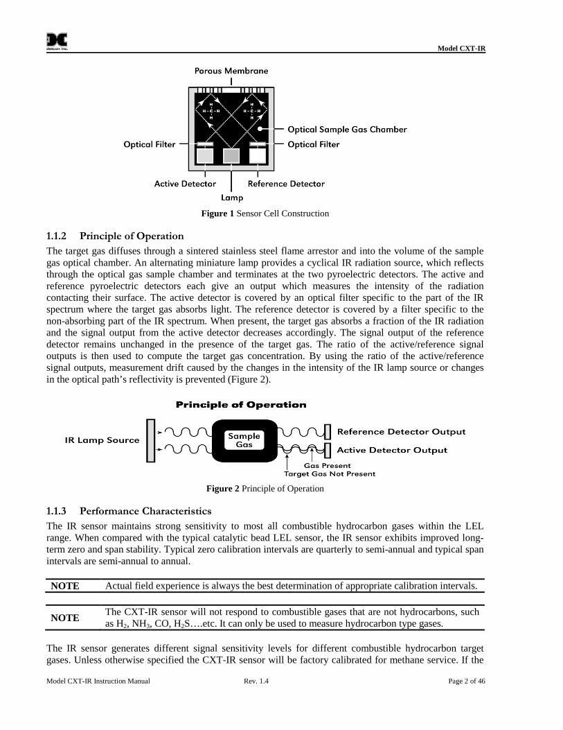
The NDIR sensor consists of (Figure 1); one infrared lamp source,
two pyroelectric detectors (active and reference),
and one optical gas sample chamber.
The lamp source produces infrared radiation, which interacts with the target gas as it is reflected throughthe optical gas sample chamber. The infrared radiation contacts each of the two pyroelectric detectors at thecompletion of the optical path. The active pyroelectric detector is covered by a filter specific to the part ofthe IR spectrum where the target gas absorbs light. The reference pyroelectric detector is covered by a filterspecific to the non-absorbing part of the IR spectrum. When the target gas is present, it absorbs IR radiationand the signal output from the active detective decreases accordingly. The reference detector outputremains unchanged. The ratio of the active and reference detector outputs are then used to compute thetarget gas concentration.
The technique is referred to as non-selective and may be used to monitor most any combustiblehydrocarbon gas. Unlike catalytic bead type sensors, Detcon IR sensors are completely resistant topoisoning from corrosive gases and can operate in the absence of an oxygen background. The sensors arecharacteristically stable and capable of providing reliable performance for periods exceeding 5 years inmost industrial environments.
Model CXT-IR
Model CXT-IR Instruction Manual Rev. 1.4 Page 2 of 46
Figure 1 Sensor Cell Construction
1.1.2 Principle of Operation
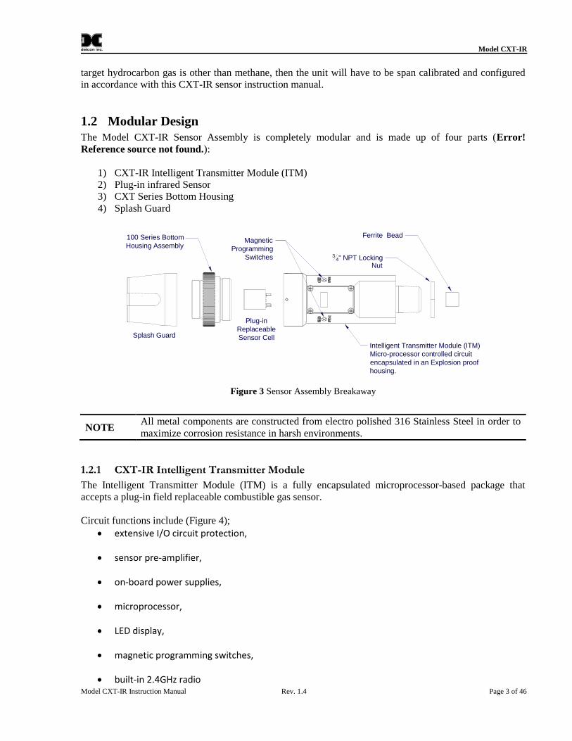
The target gas diffuses through a sintered stainless steel flame arrestor and into the volume of the samplegas optical chamber. An alternating miniature lamp provides a cyclical IR radiation source, which reflectsthrough the optical gas sample chamber and terminates at the two pyroelectric detectors. The active andreference pyroelectric detectors each give an output which measures the intensity of the radiationcontacting their surface. The active detector is covered by an optical filter specific to the part of the IRspectrum where the target gas absorbs light. The reference detector is covered by a filter specific to thenon-absorbing part of the IR spectrum. When present, the target gas absorbs a fraction of the IR radiationand the signal output from the active detector decreases accordingly. The signal output of the referencedetector remains unchanged in the presence of the target gas. The ratio of the active/reference signaloutputs is then used to compute the target gas concentration. By using the ratio of the active/referencesignal outputs, measurement drift caused by the changes in the intensity of the IR lamp source or changesin the optical path’s reflectivity is prevented (Figure 2).
Figure 2 Principle of Operation
1.1.3 Performance Characteristics
The IR sensor maintains strong sensitivity to most all combustible hydrocarbon gases within the LELrange. When compared with the typical catalytic bead LEL sensor, the IR sensor exhibits improved long-term zero and span stability. Typical zero calibration intervals are quarterly to semi-annual and typical spanintervals are semi-annual to annual.
NOTE Actual field experience is always the best determination of appropriate calibration intervals.
NOTEThe CXT-IR sensor will not respond to combustible gases that are not hydrocarbons, suchas H2, NH3, CO, H2S….etc. It can only be used to measure hydrocarbon type gases.
The IR sensor generates different signal sensitivity levels for different combustible hydrocarbon targetgases. Unless otherwise specified the CXT-IR sensor will be factory calibrated for methane service. If the
Model CXT-IR
Model CXT-IR Instruction Manual Rev. 1.4 Page 3 of 46
target hydrocarbon gas is other than methane, then the unit will have to be span calibrated and configuredin accordance with this CXT-IR sensor instruction manual.
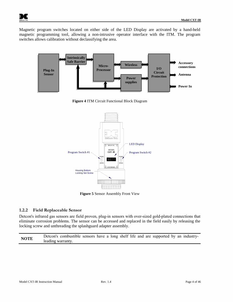
1.2 Modular DesignThe Model CXT-IR Sensor Assembly is completely modular and is made up of four parts (Error!Reference source not found.):
Intelligent Transmitter Module (ITM)Micro-processor controlled circuitencapsulated in an Explosion proofhousing.
MagneticProgramming
Switches
Splash Guard
34" NPT Locking
Nut
Ferrite Bead
Figure 3 Sensor Assembly Breakaway
NOTEAll metal components are constructed from electro polished 316 Stainless Steel in order tomaximize corrosion resistance in harsh environments.
1.2.1 CXT-IR Intelligent Transmitter Module
The Intelligent Transmitter Module (ITM) is a fully encapsulated microprocessor-based package thataccepts a plug-in field replaceable combustible gas sensor.
Circuit functions include (Figure 4); extensive I/O circuit protection,
sensor pre-amplifier,
on-board power supplies,
microprocessor,
LED display,
magnetic programming switches,
built-in 2.4GHz radio
Model CXT-IR
Model CXT-IR Instruction Manual Rev. 1.4 Page 4 of 46
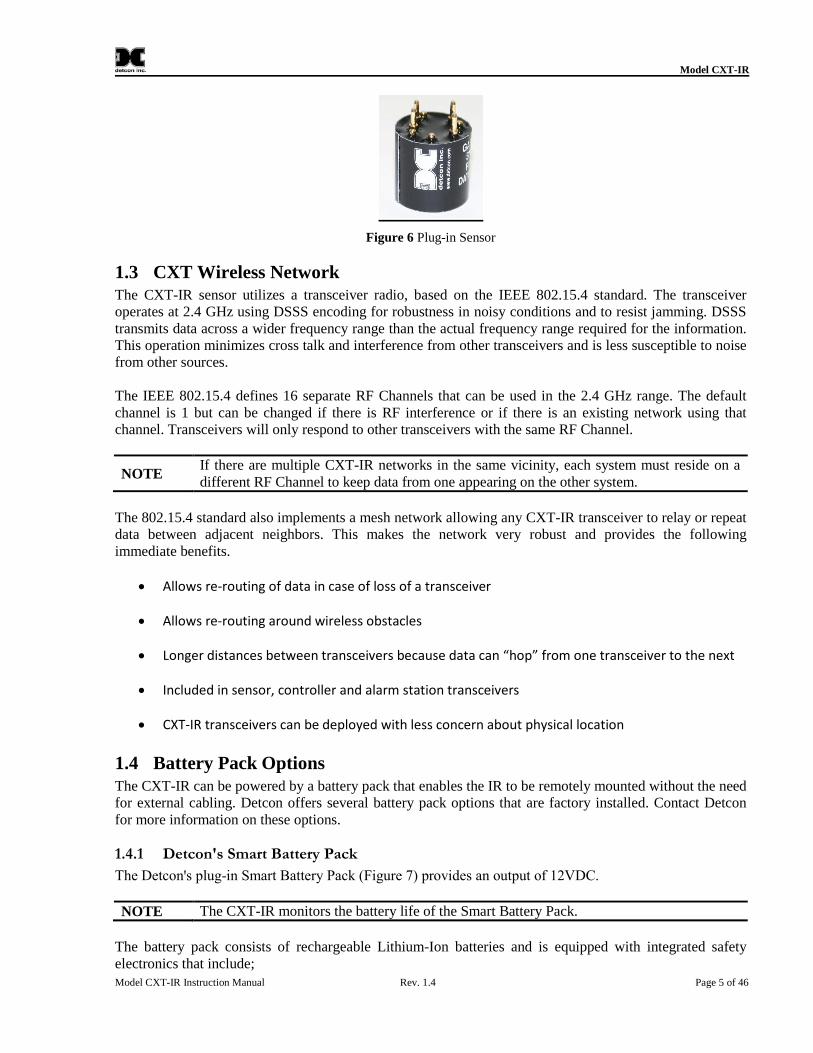
Magnetic program switches located on either side of the LED Display are activated by a hand-heldmagnetic programming tool, allowing a non-intrusive operator interface with the ITM. The programswitches allows calibration without declassifying the area.
Figure 4 ITM Circuit Functional Block Diagram
Program Switch #1
LED Display
Program Switch #2
PGM2
SPAN
PGM1
ZERO
detcon inc.
MODEL
CXT- IR
detcon inc.
H2S Sensor
Housing BottomLocking Set-Screw
Figure 5 Sensor Assembly Front View
1.2.2 Field Replaceable Sensor
Detconꞌs infrared gas sensors are field proven, plug-in sensors with over-sized gold-plated connections that eliminate corrosion problems. The sensor can be accessed and replaced in the field easily by releasing thelocking screw and unthreading the splashguard adapter assembly.
NOTEDetconꞌs combustible sensors have a long shelf life and are supported by an industry-leading warranty.
I/OCircuit
Protection
Accessoryconnections
Antenna
Power In
Wireless
Powersupplies
Micro-Processor
IntrinsicallySafe Barrier
Plug-InSensor
Model CXT-IR
Model CXT-IR Instruction Manual Rev. 1.4 Page 5 of 46
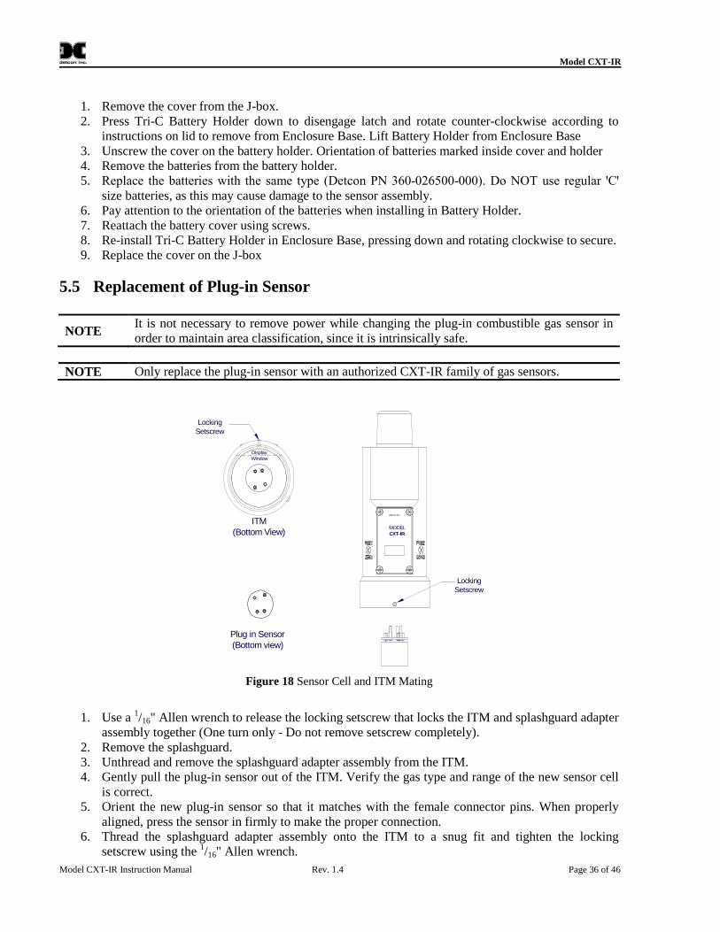
Figure 6 Plug-in Sensor
1.3 CXT Wireless NetworkThe CXT-IR sensor utilizes a transceiver radio, based on the IEEE 802.15.4 standard. The transceiveroperates at 2.4 GHz using DSSS encoding for robustness in noisy conditions and to resist jamming. DSSStransmits data across a wider frequency range than the actual frequency range required for the information.This operation minimizes cross talk and interference from other transceivers and is less susceptible to noisefrom other sources.
The IEEE 802.15.4 defines 16 separate RF Channels that can be used in the 2.4 GHz range. The defaultchannel is 1 but can be changed if there is RF interference or if there is an existing network using thatchannel. Transceivers will only respond to other transceivers with the same RF Channel.
NOTEIf there are multiple CXT-IR networks in the same vicinity, each system must reside on adifferent RF Channel to keep data from one appearing on the other system.
The 802.15.4 standard also implements a mesh network allowing any CXT-IR transceiver to relay or repeatdata between adjacent neighbors. This makes the network very robust and provides the followingimmediate benefits.
Allows re-routing of data in case of loss of a transceiver
Allows re-routing around wireless obstacles
Longer distances between transceivers because data can “hop” from one transceiver to the next
Included in sensor, controller and alarm station transceivers
CXT-IR transceivers can be deployed with less concern about physical location
1.4 Battery Pack OptionsThe CXT-IR can be powered by a battery pack that enables the IR to be remotely mounted without the needfor external cabling. Detcon offers several battery pack options that are factory installed. Contact Detconfor more information on these options.
1.4.1 Detconꞌs Smart Battery Pack
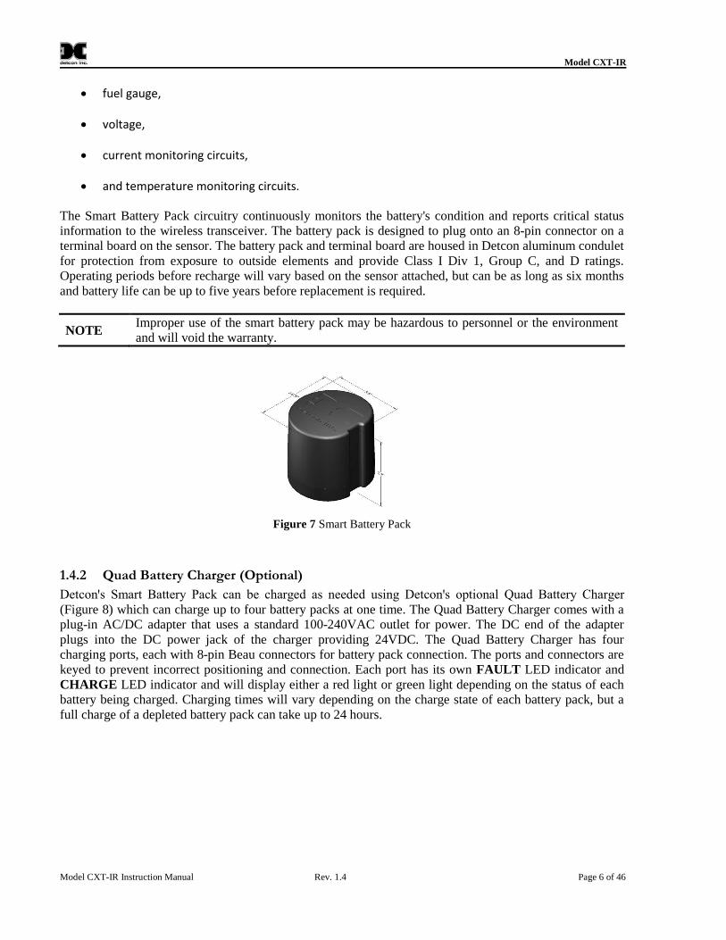
The Detconꞌs plug-in Smart Battery Pack (Figure 7) provides an output of 12VDC.
NOTE The CXT-IR monitors the battery life of the Smart Battery Pack.
The battery pack consists of rechargeable Lithium-Ion batteries and is equipped with integrated safetyelectronics that include;
Model CXT-IR
Model CXT-IR Instruction Manual Rev. 1.4 Page 6 of 46
fuel gauge,
voltage,
current monitoring circuits,
and temperature monitoring circuits.
The Smart Battery Pack circuitry continuously monitors the battery's condition and reports critical statusinformation to the wireless transceiver. The battery pack is designed to plug onto an 8-pin connector on aterminal board on the sensor. The battery pack and terminal board are housed in Detcon aluminum conduletfor protection from exposure to outside elements and provide Class I Div 1, Group C, and D ratings.Operating periods before recharge will vary based on the sensor attached, but can be as long as six monthsand battery life can be up to five years before replacement is required.
NOTEImproper use of the smart battery pack may be hazardous to personnel or the environmentand will void the warranty.
Figure 7 Smart Battery Pack
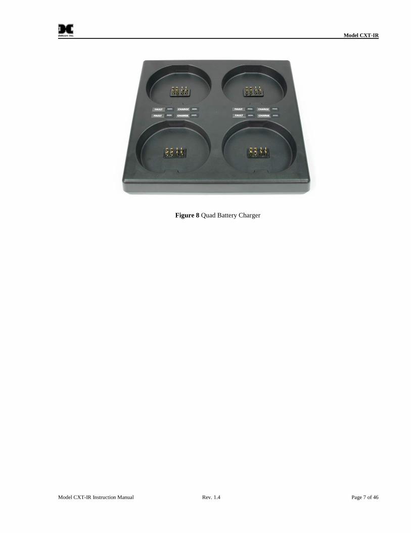
1.4.2 Quad Battery Charger (Optional)
Detconꞌs Smart Battery Pack can be charged as needed using Detconꞌs optional Quad Battery Charger (Figure 8) which can charge up to four battery packs at one time. The Quad Battery Charger comes with aplug-in AC/DC adapter that uses a standard 100-240VAC outlet for power. The DC end of the adapterplugs into the DC power jack of the charger providing 24VDC. The Quad Battery Charger has fourcharging ports, each with 8-pin Beau connectors for battery pack connection. The ports and connectors arekeyed to prevent incorrect positioning and connection. Each port has its own FAULT LED indicator andCHARGE LED indicator and will display either a red light or green light depending on the status of eachbattery being charged. Charging times will vary depending on the charge state of each battery pack, but afull charge of a depleted battery pack can take up to 24 hours.
Model CXT-IR
Model CXT-IR Instruction Manual Rev. 1.4 Page 7 of 46
Figure 8 Quad Battery Charger
Model CXT-IR
Model CXT-IR Instruction Manual Rev. 1.4 Page 8 of 46
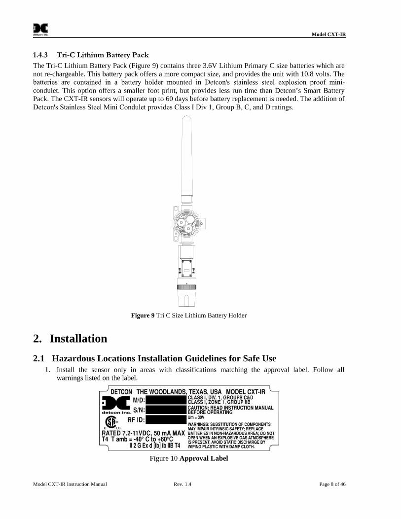
1.4.3 Tri-C Lithium Battery Pack
The Tri-C Lithium Battery Pack (Figure 9) contains three 3.6V Lithium Primary C size batteries which arenot re-chargeable. This battery pack offers a more compact size, and provides the unit with 10.8 volts. Thebatteries are contained in a battery holder mounted in Detconꞌs stainless steel explosion proof mini-condulet. This option offers a smaller foot print, but provides less run time than Detcon’s Smart BatteryPack. The CXT-IR sensors will operate up to 60 days before battery replacement is needed. The addition ofDetconꞌs Stainless Steel Mini Condulet provides Class I Div 1, Group B, C, and D ratings.
Figure 9 Tri C Size Lithium Battery Holder
2. Installation
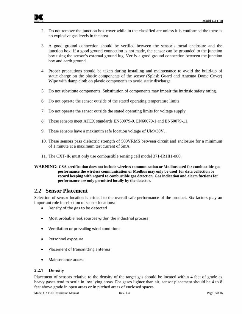
2.1 Hazardous Locations Installation Guidelines for Safe Use1. Install the sensor only in areas with classifications matching the approval label. Follow all
warnings listed on the label.
Figure 10 Approval Label
Model CXT-IR
Model CXT-IR Instruction Manual Rev. 1.4 Page 9 of 46
2. Do not remove the junction box cover while in the classified are unless it is conformed the there isno explosive gas levels in the area.
3. A good ground connection should be verified between the sensor’s metal enclosure and thejunction box. If a good ground connection is not made, the sensor can be grounded to the junctionbox using the sensor’s external ground lug. Verify a good ground connection between the junctionbox and earth ground.
4. Proper precautions should be taken during installing and maintenance to avoid the build-up ofstatic charge on the plastic components of the sensor (Splash Guard and Antenna Dome Cover)Wipe with damp cloth on plastic components to avoid static discharge.
5. Do not substitute components. Substitution of components may impair the intrinsic safety rating.
6. Do not operate the sensor outside of the stated operating temperature limits.
7. Do not operate the sensor outside the stated operating limits for voltage supply.
8. These sensors meet ATEX standards EN60079-0. EN60079-1 and EN60079-11.
9. These sensors have a maximum safe location voltage of UM=30V.
10. These sensors pass dielectric strength of 500VRMS between circuit and enclosure for a minimumof 1 minute at a maximum test current of 5mA.
11. The CXT-IR must only use combustible sensing cell model 371-IR1II1-000.
WARNING: CSA certification does not include wireless communication or Modbus used for combustible gasperformance.the wireless communication or Modbus may only be used for data collection orrecord keeping with regard to combustible gas detection. Gas indication and alarm fnctions forperformance are only permitted locally by the detector.
2.2 Sensor PlacementSelection of sensor location is critical to the overall safe performance of the product. Six factors play animportant role in selection of sensor locations:
Density of the gas to be detected
Most probable leak sources within the industrial process
Ventilation or prevailing wind conditions
Personnel exposure
Placement of transmitting antenna
Maintenance access
2.2.1 Density
Placement of sensors relative to the density of the target gas should be located within 4 feet of grade asheavy gases tend to settle in low lying areas. For gases lighter than air, sensor placement should be 4 to 8feet above grade in open areas or in pitched areas of enclosed spaces.
Model CXT-IR
Model CXT-IR Instruction Manual Rev. 1.4 Page 10 of 46
2.2.2 Leak Sources
The most probable leak sources within an industrial process include flanges, valves, and tubing connectionsof the sealed type where seals may either fail or wear. Other leak sources are best determined by facilityengineers with experience in similar processes.
2.2.3 Ventilation
Normal ventilation or prevailing wind conditions can dictate efficient location of gas sensors in a mannerwhere the migration of gas clouds is quickly detected.
2.2.4 Personnel Exposure
The undetected migration of gas clouds should not be allowed to approach concentrated personnel areassuch as control rooms, maintenance or warehouse buildings. A more general and applicable sensor locationis combining leak source and perimeter protection in the best possible configuration.
2.2.5 Maintenance Access
Consideration should be given to providing easy access for maintenance personnel and the consequences ofclose proximity to contaminants that may foul the sensor prematurely.
NOTEIn all installations the gas sensor should point straight down (Figure 11). Improper sensororientation may result in false readings and permanent sensor damage.
2.2.6 Placement of RF Antenna
Placement of the sensor should have consideration made for line of sight RF transmissions. The devicesshould be placed in a reasonable proximity to other devices in the network. Obstacles between CXTtransceivers can impact RF line-of-sight and may result in communication problems. The CXT sensorshould be in view of at least one other transceiver.
2.2.7 Additional Placement Considerations
The sensor should not be positioned where it may be sprayed or coated with surface contaminatingsubstances. Painting sensor assemblies is prohibited.
Although the sensor is designed to be RFI resistant, it should not be mounted in close proximity to high-powered radio transmitters or similar RFI generating equipment.
When possible mount in an area void of high wind, accumulating dust, rain, or splashing from hose spray,direct steam releases, and continuous vibration. If the sensor cannot be mounted away from theseconditions then make sure the Detcon Harsh Location Dust Guard accessory is used.
Do not mount in locations where temperatures will exceed the operating temperature limits of the sensor.Where direct sunlight leads to exceeding the high temperature-operating limit, use a sunshade to helpreduce temperature.
2.3 Sensor Contaminants and InterferenceDetcon CXT-IR combustible hydrocarbon gas sensors may be adversely affected by exposure to certainairborne substances. Loss of sensitivity or corrosion may be gradual if such materials are present insufficient concentrations.
The performance of the IR sensor may be impaired during operation in the presence of substances that cancause corrosion on gold plating. Other inhibiting substances are those that can coat the internal walls of theoptical chamber and reduce reflectivity. These include but are not limited to heavy oil deposits,
Model CXT-IR
Model CXT-IR Instruction Manual Rev. 1.4 Page 11 of 46
dust/powder, water condensation, and salt formation. Continuous and high concentrations of corrosivegases (such as Cl2, H2S, HCl …etc.) may also have a detrimental long-term effect on the sensorꞌs service life.
The presence of such substances in an area does not preclude the use of this sensor technology, although itis likely that the sensor lifetime will be shorter as a result. Use of this sensor in these environments mayrequire more frequent calibration checks to ensure safe system performance.
For the CXT-IR combustible gas sensors there are no known cross-interference gases that are notcombustible hydrocarbon gases.
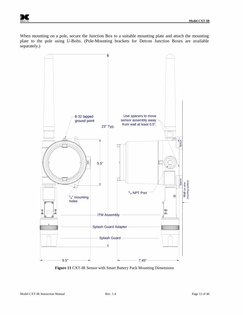
2.4 Sensor MountingThe CXT-IR should be vertically oriented so that the sensor points straight downward (Figure 11). Theexplosion-proof enclosure or junction box is typically mounted on a wall or pole. Detcon provides aselection of standard junction boxes in both Aluminum and Stainless Steel.
NOTEIf wall mounting without a mounting plate, ensure to use at least 0.5"spacers under theDetcon Aluminum Junction Box’s 1/4" mounting holes to move the sensor assembly awayfrom the wall and allow access clearance to the sensor assembly.
Model CXT-IR
Model CXT-IR Instruction Manual Rev. 1.4 Page 12 of 46
When mounting on a pole, secure the Junction Box to a suitable mounting plate and attach the mountingplate to the pole using U-Bolts. (Pole-Mounting brackets for Detcon Junction Boxes are availableseparately.)
8-32 tappedground point
7.45"
34 NPT Port
9.5"
Wa
ll(o
ro
the
r
mou
ntin
gsu
rface)
Splash Guard Adapter
Splash Guard
ITM Assembly
23" Typ.
Use spacers to movesensor assembly awayfrom wall at least 0.5".
Sp
acer
14" mounting
holes
Spacer
5.5"
Figure 11 CXT-IR Sensor with Smart Battery Pack Mounting Dimensions
Model CXT-IR
Model CXT-IR Instruction Manual Rev. 1.4 Page 13 of 46
6-32 tapped
ground point
4.1"
34 NPT Port
3.64"
Ø0.4 X 0.475"mountingholes
Splash Guard Adapter
Splash Guard
ITM Assembly
3.45"
22"Typ.
Mini Condulet withBattery Holder andBatteries
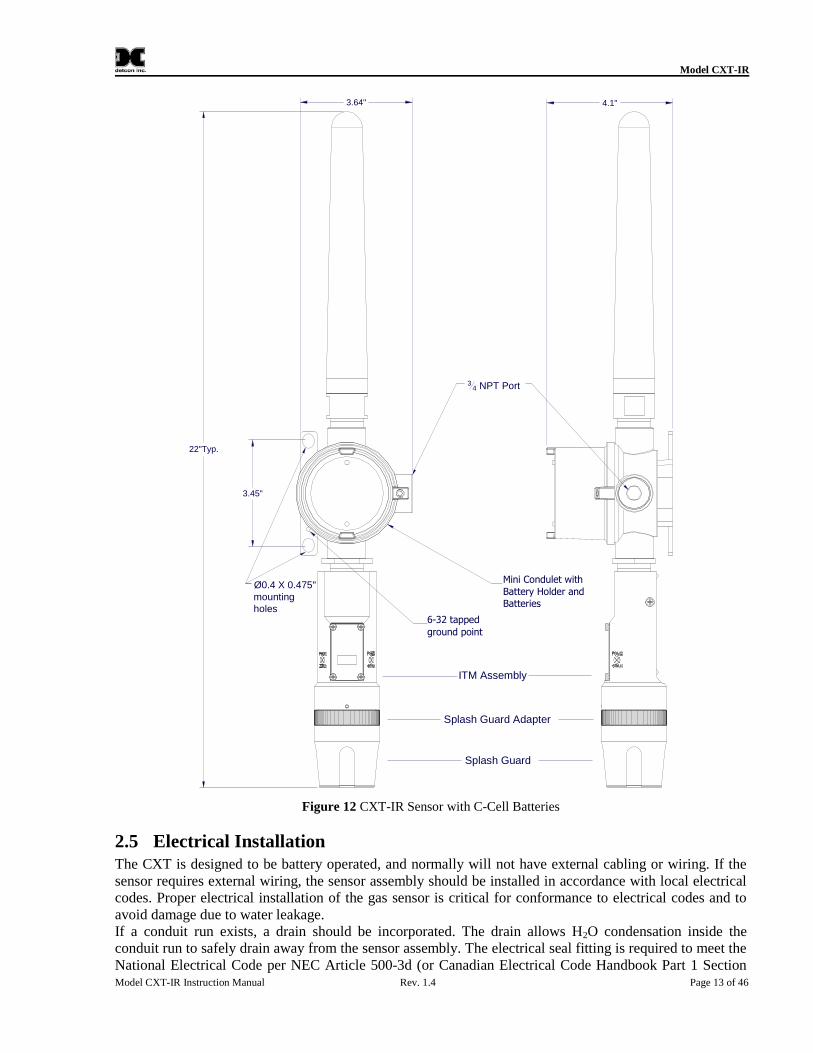
Figure 12 CXT-IR Sensor with C-Cell Batteries
2.5 Electrical InstallationThe CXT is designed to be battery operated, and normally will not have external cabling or wiring. If thesensor requires external wiring, the sensor assembly should be installed in accordance with local electricalcodes. Proper electrical installation of the gas sensor is critical for conformance to electrical codes and toavoid damage due to water leakage.If a conduit run exists, a drain should be incorporated. The drain allows H2O condensation inside theconduit run to safely drain away from the sensor assembly. The electrical seal fitting is required to meet theNational Electrical Code per NEC Article 500-3d (or Canadian Electrical Code Handbook Part 1 Section
Model CXT-IR
Model CXT-IR Instruction Manual Rev. 1.4 Page 14 of 46
18-154). Requirements for locations of electrical seals are covered under NEC Article 501-5. Electricalseals also act as a secondary seal to prevent water from entering the wiring terminal enclosure. However,they are not designed to provide an absolute watertight seal, especially when used in the verticalorientation.
NOTEA conduit seal is typically required to be located within 18" of the J-Box and SensorAssembly. Crouse Hinds type EYS2, EYD2 or equivalent are suitable for this purpose.
NOTEThe Detcon Warranty does not cover water damage resulting from water leaking into theenclosure.
NOTEAny unused ports should be blocked with suitable 3/4" male NPT plugs. Detcon supplies one3/4" NPT male plug with each J-box enclosure. If connections are other than 3/4" NPT, usean appropriate male plug of like construction material.
If the Detcon CXT-IR was ordered with battery packs, no wiring is necessary. Although an external 24Vsource can be applied in some instances. If an external power source is incorporated, wire the externalpower source to the Terminal Interconnect board as prescribed in Figure 13.
CAUTION
Do not apply System power to the sensor until all wiring is properly terminated(2.6 Initial Start Up).
2.5.1 Applying Power to the Unit
CAUTION
A 24V solar panel is the most common option for supplying external power. Asolar panel will recharge the Detcon Smart Battery Pack. It CANNOT be used withthe C-cells. A 24V input with the C-cells will damage the cells.
1. Remove the junction box cover.
2. If external power is to be applied to the unit, connect incoming 24V to the terminal labeled "+" and24V Return to the terminal labeled "-".
3. Install the batteries.
NOTEThe safety approvals require removing entire sensor assembly to a non-hazardous areabefore changing out the batteries or battery pack.
a) For units utilizing the 12V Smart Battery Pack (Figure 13), plug the battery pack into theterminal board. If the sensor has a power switch, power will not be applied until the switch isturned on. If the unit does not have a power switch, power will be applied, and the unit willproceed to power up (Section 2.6).
b) If the unit utilizes the C sized lithium 3.6V batteries and battery holder, install the batteriesproperly. If the sensor has a power switch, power will not be applied until the switch is turnedon. If the unit does not have a power switch, power will be applied, and the unit will proceed topower up (Section2.6).
Model CXT-IR
Model CXT-IR Instruction Manual Rev. 1.4 Page 15 of 46
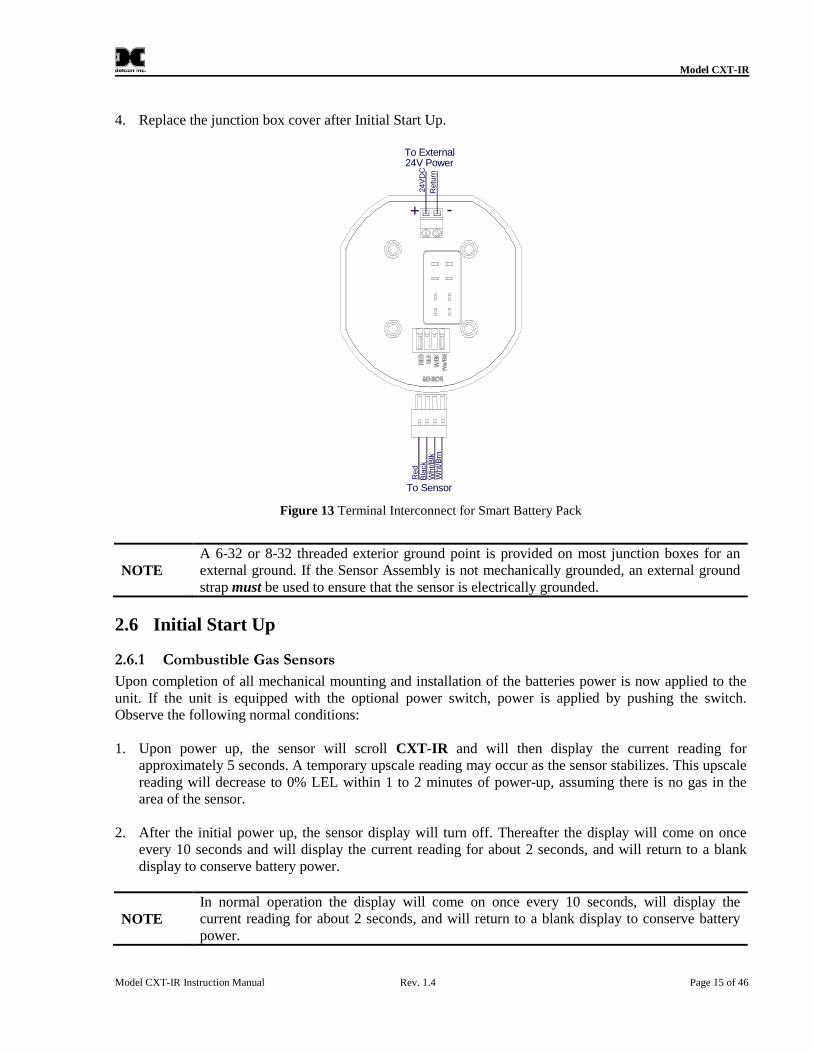
4. Replace the junction box cover after Initial Start Up.
Bla
ckW
ht/
Blk
Wh
t/B
rn
Re
d
To Sensor
24V PowerTo External
Re
turn
24
VD
C
+ -
Figure 13 Terminal Interconnect for Smart Battery Pack
NOTEA 6-32 or 8-32 threaded exterior ground point is provided on most junction boxes for anexternal ground. If the Sensor Assembly is not mechanically grounded, an external groundstrap must be used to ensure that the sensor is electrically grounded.
2.6 Initial Start Up
2.6.1 Combustible Gas Sensors
Upon completion of all mechanical mounting and installation of the batteries power is now applied to theunit. If the unit is equipped with the optional power switch, power is applied by pushing the switch.Observe the following normal conditions:
1. Upon power up, the sensor will scroll CXT-IR and will then display the current reading forapproximately 5 seconds. A temporary upscale reading may occur as the sensor stabilizes. This upscalereading will decrease to 0% LEL within 1 to 2 minutes of power-up, assuming there is no gas in thearea of the sensor.
2. After the initial power up, the sensor display will turn off. Thereafter the display will come on onceevery 10 seconds and will display the current reading for about 2 seconds, and will return to a blankdisplay to conserve battery power.
NOTEIn normal operation the display will come on once every 10 seconds, will display thecurrent reading for about 2 seconds, and will return to a blank display to conserve batterypower.
Model CXT-IR
Model CXT-IR Instruction Manual Rev. 1.4 Page 16 of 46
2.6.2 Initial Operational Tests
After a warm up period of 1 hour (or when zero has stabilized), the sensor should be checked to verifysensitivity to the target gas.
2.6.3 Material Requirements
Detcon Splash Guard with integral Cal Port and with Wind Guard (PN 613-120000-700)
-OR-Detcon Teflon Calibration Adapter for highly reactive gases (PN 943-01747-T05)
Detcon Span Gas; 50% of range target gas in balance N2 or Air at fixed flow rate between 200-
500cc/min (500cc/min is preferred)
NOTECalibration gas generators using perm tubes or electrochemical sources may be used inplace of span gas cylinders.
12. Attach the calibration adapter to the Splashguard Adapter Assembly or connect tubing to integralcal port. It is recommended that the Wind Guard (Detcon PN 943-000000-000) is installed over theSplash Guard during calibration.
13. Apply the test gas at a controlled flow rate of 200 - 500cc/min (500cc/min is the recommendedflow). Observe that the ITM display increases to a level near that of the applied calibration gasvalue.
NOTEWind Guard must be used when calibrating with the integral cal port to ensure propercalibration.
14. Remove test gas and observe that the display decreases to 0.
15. If a calibration adapter was used during these tests, remove it from the unit, and re-install theSplash Guard.
16. If the wind guard was used, remove the wind guard.
Initial operational tests are complete.
CXT-IR Combustible gas sensors are factory calibrated prior to shipment, and should not requiresignificant adjustment on start up. However, it is recommended that a complete calibration test andadjustment be performed 16 to 24 hours after power-up. Refer to calibration instructions in Section 3.3.
Model CXT-IR
Model CXT-IR Instruction Manual Rev. 1.4 Page 17 of 46
3. Operation
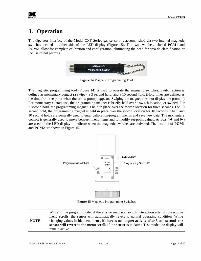
The Operator Interface of the Model CXT Series gas sensors is accomplished via two internal magneticswitches located to either side of the LED display (Figure 15). The two switches, labeled PGM1 andPGM2, allow for complete calibration and configuration, eliminating the need for area de-classification orthe use of hot permits.
Figure 14 Magnetic Programming Tool
The magnetic programming tool (Figure 14) is used to operate the magnetic switches. Switch action isdefined as momentary contact (a swipe), a 3 second hold, and a 10 second hold. (Hold times are defined asthe time from the point when the arrow prompt appears. Swiping the magnet does not display the prompt.)For momentary contact use, the programming magnet is briefly held over a switch location, or swiped. For3 second hold, the programming magnet is held in place over the switch location for three seconds. For 10second hold, the programming magnet is held in place over the switch location for 10 seconds. The 3 and10 second holds are generally used to enter calibration/program menus and save new data. The momentarycontact is generally used to move between menu items and to modify set-point values. Arrows (◄ and ►)are used on the LED display to indicate when the magnetic switches are activated. The location of PGM1and PGM2 are shown in Figure 15.
detcon inc.
MODELCXT-IR
Programming Switch #1
LED Display
Programming Switch #2
Figure 15 Magnetic Programming Switches
NOTE
While in the program mode, if there is no magnetic switch interaction after 4 consecutivemenu scrolls, the sensor will automatically revert to normal operating condition. Whilechanging values inside menu items, if there is no magnet activity after 3 to 4 seconds thesensor will revert to the menu scroll. If the sensor is in Bump Test mode, the display willremain active.
Model CXT-IR
Model CXT-IR Instruction Manual Rev. 1.4 Page 18 of 46
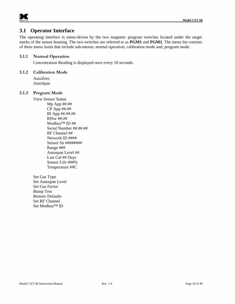
3.1 Operator InterfaceThe operating interface is menu-driven by the two magnetic program switches located under the targetmarks of the sensor housing. The two switches are referred to as PGM1 and PGM2. The menu list consistsof three menu items that include sub-menus; normal operation, calibration mode and, program mode.
3.1.1 Normal Operation
Concentration Reading is displayed once every 10 seconds.
3.1.2 Calibration Mode
AutoZeroAutoSpan
3.1.3 Program Mode
View Sensor StatusMp App ##.##CP App ##.##Rf App ##.##.##RfSw ##.##Modbus™ ID ##Serial Number ##.##.##RF Channel ##Network ID ####Sensor Sn ########Range ###Autospan Level ##Last Cal ## DaysSensor Life ###%Temperature ##C
Set Gas TypeSet Autospan LevelSet Gas FactorBump TestRestore DefaultsSet RF ChannelSet Modbus™ ID
Model CXT-IR
Model CXT-IR Instruction Manual Rev. 1.4 Page 19 of 46
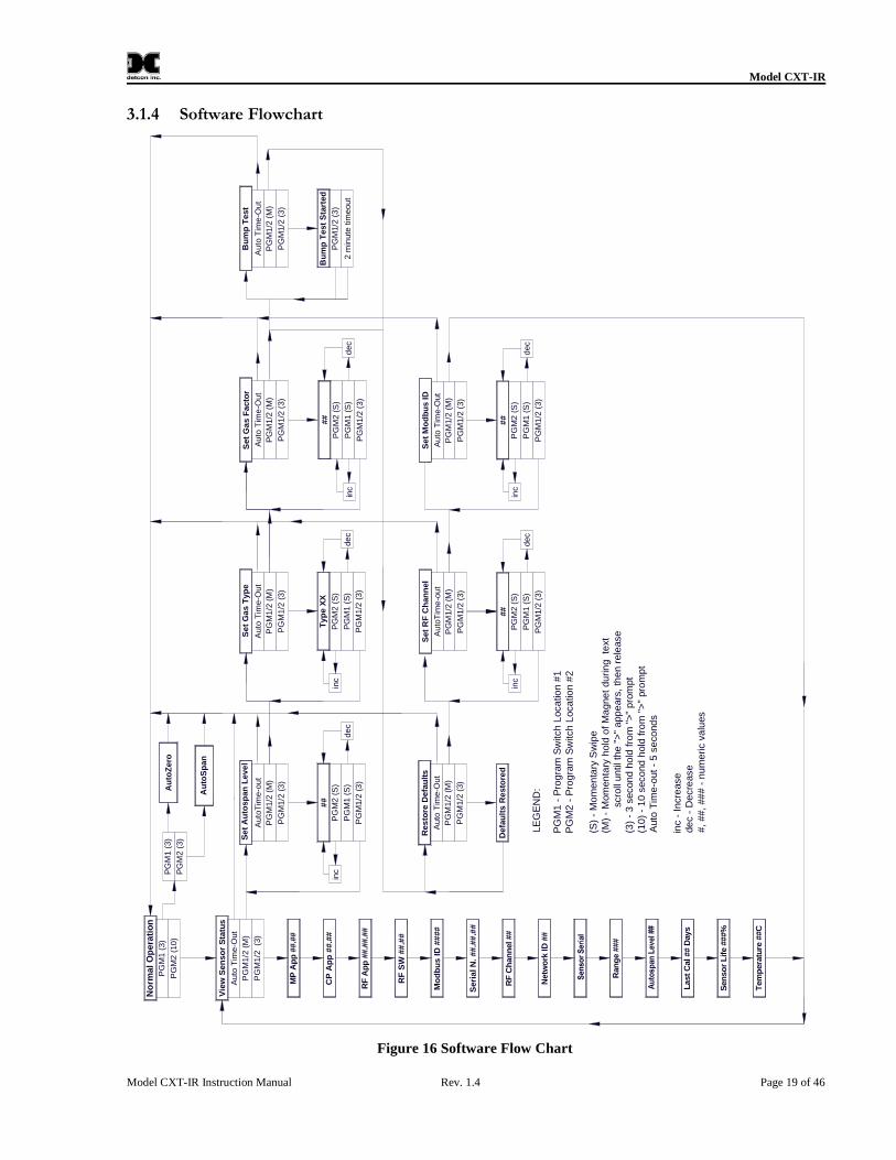
3.1.4 Software Flowchart
de
c
LE
GE
ND
:
PG
M1
-P
rog
ram
Sw
itch
Loca
tion
#1
PG
M2
-P
rog
ram
Sw
itch
Loca
tion
#2
(S)
-M
om
en
tary
Sw
ipe
(M)
-M
om
en
tary
hold
of
Ma
gne
tdu
rin
gte
xtsc
roll
un
tilth
e">
"a
pp
ears
,th
en
rele
ase
(3)
-3
secon
dho
ldfr
om
">"
pro
mpt
(10
)-
10
seco
nd
hold
fro
m">
"pro
mp
tA
uto
Tim
e-o
ut
-5
se
cond
s
inc
-In
cre
ase
de
c-
De
cre
ase
#,
##
,##
#-
nu
me
ric
valu
es
Seri
alN
.##.#
#.#
#
Tem
pera
ture
##C
RF
Ch
an
nel##
Au
toZ
ero
PG
M1
(3)
PG
M2
(10
)P
GM
2(3
)
RF
Ap
p##.#
#.#
#
CP
Ap
p##.#
#
RF
SW
##
.##
Mo
db
us
ID##
##
inc
Auto
Tim
e-O
ut
Vie
wS
en
so
rS
tatu
s
PG
M1/2
(3)
PG
M1/2
(M)
MP
Ap
p##.#
#
PG
M2
(S)
PG
M1/2
(3)
PG
M1
(S)
##
Auto
Tim
e-o
ut
PG
M1/2
(3)
PG
M1/2
(M)
Au
toS
pan
No
rmal
Op
era
tio
n
PG
M1
(3)
Au
toT
ime
-Out
Auto
Tim
e-O
ut
inc
PG
M2
(S)
PG
M1/2
(3)
PG
M1
(S)
Typ
eX
X
PG
M1/2
(3)
PG
M1/2
(M)
dec
PG
M1
/2(3
)
PG
M1/2
(M)
Set
Ga
sF
acto
r
PG
M1/2
(M)
Defa
ult
sR
esto
red
PG
M1/2
(3)
Res
tore
Defa
ult
s
Auto
Tim
e-O
ut
dec
inc
PG
M2
(S)
PG
M1/2
(3)
PG
M1
(S)
##
Auto
Tim
e-o
ut
PG
M1/2
(3)
PG
M1/2
(M)
Set
RF
Ch
an
nel
Au
toT
ime-O
ut
inc
PG
M2
(S)
PG
M1
/2(3
)
PG
M1
(S)
##
PG
M1
/2(3
)
PG
M1/2
(M)
Set
Mo
db
us
ID
dec
Se
tA
uto
sp
an
Leve
l
Netw
ork
ID##
Ran
ge
###
Last
Cal##
Days
Sen
so
rL
ife
###%
Se
tG
as
Typ
e
Auto
Tim
e-O
ut
PG
M1/2
(3)
Bu
mp
Test
Sta
rted
PG
M1/2
(3)
PG
M1
/2(M
)
Bu
mp
Test
2m
inute
timeout
PG
M2
(S)
PG
M1
/2(3
)
PG
M1
(S)
##
inc
dec
Figure 16 Software Flow Chart
Model CXT-IR
Model CXT-IR Instruction Manual Rev. 1.4 Page 20 of 46
3.2 Normal OperationIn normal operation, the ITM Display will be blank and will display the gas reading once every 10 secondsfor about 2 seconds (normally appear as 0). At any time swiping a magnet across either PGM1 or PGM2will cause the ITM to display the units and gas type (i.e. % LEL or PPM H2S). If the sensor is activelyexperiencing any diagnostic faults, a swipe of the magnet will cause the display to scroll the fault condition.Refer to Section 3.12for more information on fault conditions.
3.3 Calibration ModeZero and span calibration should be performed on a routine basis (quarterly minimum is advised) to ensurereliable performance. If a sensor has been exposed to any de-sensitizing gases, or to very high over-rangecombustible gas levels, re-calibration should be considered. Unless otherwise specified, span adjustment isrecommended at 50% of the full scale range.
To enter Calibration Mode hold the magnet over PGM1 for 3 seconds. If the sensor is experiencing a faultcondition the "◄" prompt will not appear until the fault(s) have been displayed. When the ITM entersCalibration Mode the display will scroll Pgm1=Zero . . . Pgm2=Span twice before returning to NormalMode (about 5 seconds).
3.3.1 AutoZero
The AutoZero function is used to zero the sensor. AutoZero should be performed periodically or asrequired. AutoZero should be considered after periods of over-range target gas exposure. Local ambient aircan be used to zero calibrate a combustible gas sensor as long as it can be confirmed that it contains notarget or interference gasses. If this cannot be confirmed then a zero air or N2 cylinder should be used.
Material Requirements: DetconMicroSafe™ Programming Magnet (PN 327-000000-000)
Detcon Splash Guard with integral Cal Port and with Wind Guard (PN 613-120000-700) -OR-
Detcon Zero Air cal gas (PN 942-001123-000) (or use ambient air if no target gas is present)
Detcon Nitrogen 99.99% (PN 942-640023-100)
NOTEThe zero gas source may be zero air or N2 if local ambient air contains target or interferencegases.
a) For combustible gas sensors, if the ambient air is known to contain no target gas content, then it can beused for zero calibration. If a zero gas cal cylinder is going to be used, attach the calibration adapterand set flow rate of 200-500cc/min (500cc/min is the recommended flow rate) and let sensor purge for1 to 2 minutes before executing the AutoZero.
NOTEWind Guard must be used when calibrating with the integral cal port to ensure propercalibration.
b) From normal operation, enter calibration mode by holding the programming magnet over PGM1 for 3seconds The display will then scroll Pgm1=Zero Pgm2=Span. Hold the programming magnet overPGM1 for 3 seconds once the "◄" prompt appears to execute AutoZero (or allow to timeout in 5seconds if AutoZero is not desired).
Model CXT-IR
Model CXT-IR Instruction Manual Rev. 1.4 Page 21 of 46
NOTEThe "◄" prompt will show that the magnetic switch is activated during the 3 second holdperiod.
NOTEUpon entering calibration mode, the Modbus™ status register bit 14 is set to signify thesensor is in-calibration mode. This bit will remain set until the program returns to normaloperation.
c) The ITM will display the following sequence of text messages as it proceeds through the AutoZerosequence:
Zero Cal . . . Setting Zero . . . Zero Saved (each will scroll twice)
d) Remove the zero gas and calibration adapter, if applicable.
3.3.2 AutoSpan
The AutoSpan function is used to span calibrate the sensor. AutoSpan should be performed periodically oras required. AutoSpan should be considered after periods of over-range target gas exposure. Unlessotherwise specified, span adjustment is recommended at 50% of range. This function is called AUTOSPAN.
NOTEBefore performing AutoSpan calibration, verify that the AutoSpan level matches the spancalibration gas concentration as described in Section3.7 Set AutoSpan level.
Detcon Span Gas. Recommended span gas is 50% of range with target gas. Other suitable span gas
sources containing the target gas in air or N2 balance are acceptable.
NOTE Contact Detcon for ordering information on span gas cylinders.
NOTE
A target gas concentration of 50% of range is strongly recommended. This should besupplied at a controlled flow rate of 200 to 500cc/min, with 500cc/min being therecommended flow rate. Other concentrations can be used if they fall within allowablelevels of 5% to 100% of range.
NOTEIt is generally not advised to use other gasses to cross-calibrate for span. Cross-calibrationby use of other gasses should be confirmed by Detcon.
CAUTION
Verification that the calibration gas level setting matches the calibration span gasconcentration is required before executing AutoSpan calibration. These twonumbers must be equal.
Model CXT-IR
Model CXT-IR Instruction Manual Rev. 1.4 Page 22 of 46
AutoSpan consists of entering calibration mode and following the menu-displayed instructions. The displaywill ask for the application of span gas in a specific concentration. The applied gas concentration must beequal to the calibration gas level setting. The factory default setting and recommendation for span gasconcentration is 50% of range. If a span gas containing the recommended concentration is not available,other concentrations may be used as long as they fall between 5% and 95% of range. However, anyalternate span gas concentration value must be programmed via the Set AutoSpan Level menu beforeproceeding with AutoSpan calibration. Follow the instructions a) through f) below for AutoSpancalibration.
a) Verify that the AutoSpan level is equal to the calibration span gas concentration. (Refer to View SensorStatus in Section 3.5.) If the AutoSpan level is not equal to the calibration span gas concentration,adjust the AutoSpan level as instructed in Section 3.3.2AutoSpan.
b) From normal operation, enter calibration mode by holding the programming magnet over PGM1 for 3seconds.
NOTEThe "◄"prompt will show that the magnetic switch is activated during the 3 second holdperiod.
c) The display will then scroll PGM1=Zero PGM2=Span. Hold the programming magnet over PGM2for 3 seconds to execute AutoSpan (or allow to timeout in 5 seconds if AutoSpan is not intended). TheITM will then scroll Apply XX % Gas.
NOTEUpon entering calibration mode, the Modbus™ status register bit 14 is set to signify thesensor is in-calibration mode. This bit will remain set until the program returns to normaloperation.
d) Apply the span calibration test gas for combustible gas sensors at a flow rate of 200-500cc/min(500cc/min is the recommended flow rate). As the sensor signal begins to increase the display willswitch to flashing XX reading as the ITM shows the sensorꞌs as found response to the span gaspresented. If it fails to meet the minimum in-range signal change criteria within 2 minutes, the displaywill report Range Fault twice and the ITM will return to normal operation, aborting the AutoSpansequence. The ITM will continue to report a Range Fault until a successful calibration is completed.
NOTEWind Guard must be used when calibrating with the integral cal port to ensure propercalibration.
Assuming acceptable sensor signal change, after 1 minute the reading will auto-adjust to the programmedAutoSpan level. The ITM then reports the following messages: Remove Gas.
e) Remove the span gas source and calibration adapter. The ITM will report a live reading as it clearstoward 0. When the reading clears below 10% of range, the ITM will display Span Complete and willrevert to normal operation. If the sensor fails to clear to less than 10% in less than 5 minutes, aClearing Fault will be reported twice and the ITM will return to normal operation, aborting theAutoSpan sequence. The ITM will continue to report a Clearing Fault until a successful calibration iscompleted.
f) AutoSpan calibration is complete.
Model CXT-IR
Model CXT-IR Instruction Manual Rev. 1.4 Page 23 of 46
NOTEIf the sensor fails the minimum signal change criteria, a Range Fault will be declared andthe Range Fault bit will be set on the Modbus™ output.
NOTEIf the sensor fails the clearing time criteria, a Clearing Fault will be declared and theClearing fault bit will be set on the Modbus™ output.
3.4 Program ModeProgram Mode provides a View Sensor Status menu to check operational and configuration parameters.Program Mode also provides for adjustment of the AutoSpan Level, Gas Factor, Gas Type and Range, andSerial ID.
The Program Mode menu items appear in the order presented below:View Sensor StatusSet Gas TypeSet AutoSpan LevelSet Gas FactorBump TestRestore DefaultsSet RF ChannelSet Modbus™ ID
3.4.1 Navigating Program Mode
From normal operation, enter program mode by holding the magnet over PGM2 for 10 seconds.
NOTEThe arrow prompt (◄ and ►) will show that the magnetic switch is activated during the 10second hold period.
The ITM will enter program mode and the display will scroll the first menu item View Sensor Status. Toadvance to the next menu item, hold the magnet over PGM1 or PGM2 while the current menu item text isscrolling. At the conclusion of the text scroll the arrow prompt for PGM2 or PGM1 will appear, andimmediately remove the magnet. The ITM will advance to the next menu item. Repeat this process until thedesired menu item is displayed.
NOTEPGM1 moves the menu items from right to left and PGM2 moves the menu items from leftto right.
To enter a menu item, hold the magnet over PGM1 or PGM2 while the menu item is scrolling. At theconclusion of the text scroll the arrow prompt for PGM2 or PGM1 will appear, continue to hold themagnet over PGM1 or PGM2 for an additional 3 to 4 seconds to enter the selected menu item. If there isno magnet activity while the menu item text is scrolling (typically 4 repeated text scrolls), the ITM willautomatically revert to normal operation.
Model CXT-IR
Model CXT-IR Instruction Manual Rev. 1.4 Page 24 of 46
3.5 View Sensor StatusView Sensor Status displays all current configuration and operational parameters including:
sensor type,
software version number,
detection range,
AutoSpan level,
days since last AutoSpan,
estimated remaining sensor life,
gas factor,
gas type,
and sensor ambient temperature.
From the View Sensor Status text scroll, hold the magnet over PGM1 or PGM2 until the arrow promptappears and continue to hold the magnet in place for an additional 3 to 4 seconds (until the display starts toscroll Status Is). The display will scroll the complete list of sensor status parameters sequentially.
When the status list sequence is complete, the ITM will revert to the View Sensor Status text scroll.The user can either:
a) review list again by executing another 3 to 4 second hold,b) move to another menu item by executing a momentary hold over PGM1 or PGM2, orc) return to normal operation via automatic timeout of about 15 seconds (the display will scroll View
Sensor Status four times and then return to normal operation).
3.6 Set Gas TypeThe IR sensor has a slightly different linearization requirement for different groupings of target gases.The two selections are;
%LEL and
%VOL.
The Set Gas Type menu function is a simple choice between these two gas type groupings.
NOTE The default value for Gas Type is methane (%LEL).
The menu item appears as: Set Gas Type.
From the Set Gas Type and Range text scroll, hold the magnet over PGM1 or PGM2 until the arrowprompt appears and continue to hold the magnet in place for an additional 3 to 4 seconds (until the displaystarts to scroll %LEL / %VOL). Swipe the magnet momentarily over PGM2 or PGM1 to change theselection until the correct choice is displayed. Hold the magnet over PGM1 or PGM2 for 3 seconds to
Model CXT-IR
Model CXT-IR Instruction Manual Rev. 1.4 Page 25 of 46
accept the new value. The display will scroll Type Saved, then Set Range followed by the currentlyselected Range. Momentarily hold the magnet over PGM1 or PGM2 to change the Range Selection untilthe correct value is displayed. Hold the magnet over PGM2 for 3 seconds to accept the new value.
Move to another menu item by executing a momentary hold, or, return to normal operation via automatictimeout of about 15 seconds (the display will scroll Set Gas Type 4 times and then return to normaloperation).
3.7 Set AutoSpan LevelSet AutoSpan Level is used to set the span gas concentration level that is being used to calibrate the sensor.This level is adjustable from 5% to 95% of range. The current setting can be viewed in View ProgramStatus.
The menu item appears as: Set AutoSpan Level.
From the Set AutoSpan Level text scroll, hold the magnet over PGM1 or PGM2 until the arrow promptappears and continue to hold the magnet in place for an additional 3-4 seconds (until the display starts toscroll Set Level). The display will switch to XX (where XX is the current gas level). Swipe the magnetmomentarily over PGM2 to increase or PGM1 to decrease the AutoSpan Level until the correct level isdisplayed. When the correct level is achieved, hold the magnet over PGM2 for 3 to 4 seconds to accept thenew value. The display will scroll Level Saved, and revert to Set AutoSpan Level text scroll.
Move to another menu item by executing a momentary hold, or return to normal operation via automatictimeout of about 15 seconds (the display will scroll Set AutoSpan Level 4 times and then return to normaloperation).
3.8 Set Gas FactorBecause of the CXT-IR sensorꞌs almost universal response to combustible hydrocarbon gases, the CXT-IR sensor can be configured and calibrated to detect a variety of combustible gases. The detected gas isreferred to as the "target gas" and the span calibration gas is referred to as the "cal gas". In cases where thecal gas is different from the target gas, the Set Gas Factor menu function is used to maintain accuracy. Thisfeature allows for a significant degree of flexibility in the detection and span calibration process.
NOTEThe default value for Gas Factor is 1.0. This would be used when the target gas is the sameas the cal gas.
Set Gas Factor is used to make the appropriate signal sensitivity adjustment when the target gas is differentfrom the cal gas. This is necessary because the IR sensor has different signal strengths for each combustiblehydrocarbon gas. The Gas Factor value is adjustable from 0.2 to 5.0. It represents the translation betweenthe target gas and the cal gas when they are different.
The menu item appears as: Set Gas Factor.
To calculate the correct Gas Factor (Table 1), take the Gas Factor of the target gas and divide by the GasFactor of the cal gas. The calculated value is the correct number to enter into the menu as the Gas Factor.
For example, if calibrating with methane when propane is the target gas, the correct Gas Factor to enterwould be 0.63/1.0 = 0.63.
Model CXT-IR
Model CXT-IR Instruction Manual Rev. 1.4 Page 26 of 46
For example, if calibrating with butane when ethane is the target gas, the correct Gas Factor to enter wouldbe 0.38/0.72=0.53.
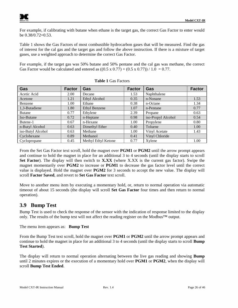
Table 1 shows the Gas Factors of most combustible hydrocarbon gases that will be measured. Find the gasof interest for the cal gas and the target gas and follow the above instruction. If there is a mixture of targetgases, use a weighted approach to determine the correct Gas Factor.
For example, if the target gas was 50% butane and 50% pentane and the cal gas was methane, the correctGas Factor would be calculated and entered as ((0.5 x 0.77) + (0.5 x 0.77)) / 1.0 = 0.77.
From the Set Gas Factor text scroll, hold the magnet over PGM1 or PGM2 until the arrow prompt appearsand continue to hold the magnet in place for an additional 3 to 4 seconds (until the display starts to scrollSet Factor). The display will then switch to X.XX (where X.XX is the current gas factor). Swipe themagnet momentarily over PGM2 to increase or PGM1 to decrease the gas factor level until the correctvalue is displayed. Hold the magnet over PGM2 for 3 seconds to accept the new value. The display willscroll Factor Saved, and revert to Set Gas Factor text scroll.
Move to another menu item by executing a momentary hold, or, return to normal operation via automatictimeout of about 15 seconds (the display will scroll Set Gas Factor four times and then return to normaloperation).
3.9 Bump TestBump Test is used to check the response of the sensor with the indication of response limited to the displayonly. The results of the bump test will not affect the reading register on the Modbus™ output.
The menu item appears as: Bump Test
From the Bump Test text scroll, hold the magnet over PGM1 or PGM2 until the arrow prompt appears andcontinue to hold the magnet in place for an additional 3 to 4 seconds (until the display starts to scroll BumpTest Started).
The display will return to normal operation alternating between the live gas reading and showing Bumpuntil 2 minutes expires or the execution of a momentary hold over PGM1 or PGM2, when the display willscroll Bump Test Ended.
Model CXT-IR
Model CXT-IR Instruction Manual Rev. 1.4 Page 27 of 46
3.10 Restore DefaultsThe CXT-IR sensor has the option to restore its internal memory settings to factory default conditions.
The menu item appears as: Restore Defaults.
From the Restore Defaults text scroll, hold the magnet over PGM2 until the arrow prompt appears andcontinue to hold the magnet in place for an additional 3 to 4 seconds (until the display starts to scrollDefaults Restored). The display will then revert to Restore Defaults text scroll.
Move to another menu item by executing a momentary hold, or, return to normal operation via automatictimeout of about 15 seconds (the display will scroll Restore Defaults four times and then return to normaloperation).
CAUTIONAfter the defaults are restored, the sensor must be recalibrated.
3.11 Set RF ChannelThe CXT-IR sensor communicates wirelessly and can be set to use unique wireless radio channel. Set RFChannel is used to set the RF radio channel. It is adjustable from 0 to 15.
The menu item appears as: Set RF Channel.
From the Set RF Channel text scroll, hold the programming magnet over PGM1 or PGM2 until the arrowprompt appears and continue to hold the magnet in place for an additional 3 to 4 seconds (until the displaystarts to scroll Set Channel). The display will then switch to XX (where XX is the current RF channel).Swipe the magnet momentarily over PGM2 to increase or PGM1 to decrease the hexadecimal numberuntil the desired ID is displayed. Hold the magnet over PGM2 for 3 to 4 seconds to accept the new value.The display will scroll Channel Saved, and revert to Set RF Channel text scroll.
Move to another menu item by executing a momentary hold, or, return to Normal Operation via automatictimeout of about 15 seconds (the display will scroll Set RF Channel four times and then return to NormalOperation).
3.11.1 Set Modbus™ ID
The CXT-IR sensor can be polled serially via RS-485 Modbus™ RTU. Set Modbus™ ID is used to set theModbus™ serial ID address. It is adjustable from 01 to 256 in hexadecimal format (01-FF) hex.
The menu item appears as: Set Modbus™ ID.
From the Set Modbus™ ID text scroll, hold the programming magnet over PGM1 or PGM2 until thearrow prompt appears and continue to hold the magnet in place for an additional 3 to 4 seconds (until thedisplay starts to scroll Set ID). The display will then switch to XX (where XX is the current ID address).Swipe the magnet momentarily over PGM2 to increase or PGM1 to decrease the hexadecimal numberuntil the desired ID is displayed. Hold the magnet over PGM2 for 3 to 4 seconds to accept the new value.The display will scroll ID Saved, and revert to Set Modbus™ ID text scroll.
Model CXT-IR
Model CXT-IR Instruction Manual Rev. 1.4 Page 28 of 46
Move to another menu item by executing a momentary hold, or, return to normal operation via automatictimeout of about 15 seconds (the display will scroll Set Modbus™ ID four times and then return to normaloperation).
3.12 Fault Diagnostic/Failsafe FeatureIf the ITM should incur a fault, the Global Fault bit will be set on the Modbus™ output. This can occur ifthe ITM detects a problem with the sensor, detects that there is no sensor connected, if the ITM has aninternal fault, or other fault condition. The Global Fault bit will be set on the Modbus™ output until theproblem is resolved. The display will show the Fault when a magnetic programming tool is swiped acrosseither PGM1 or PGM2. The error codes are defined in Section 6Troubleshooting.
4. Modbus™ TM Communications
Modbus™ communication with a CXT Sensor is normally accomplished using another wireless transceiversuch as the RXT-320 which is connected through a RS-485 interface to a Modbus™ master control unit.The control unit can then access the Modbus™ registers within the CXT to obtain readings and status of thesensor.
As with normal Modbus™ operation, there can be only one Modbus™ master that polls all the otherdevices on the network which are considered Modbus™ slaves. Each sensor must have a unique Modbus™address and be on the same RF channel (for communication) to work properly on the wireless network.Both the Modbus™ ID and the RF channel are set on the CXT sensor using the display.
The Modbus™ master control unit with RXT-320 transceiver (or equivalent) is responsible forbroadcasting requests and receiving slave device responses. The CXT sensor receives these requeststhrough its own internal transceiver and responds if the Modbus™ address and proper register set matches.The response will be received by the RXT-320 and presented to the master control unit across the RS-485interface.
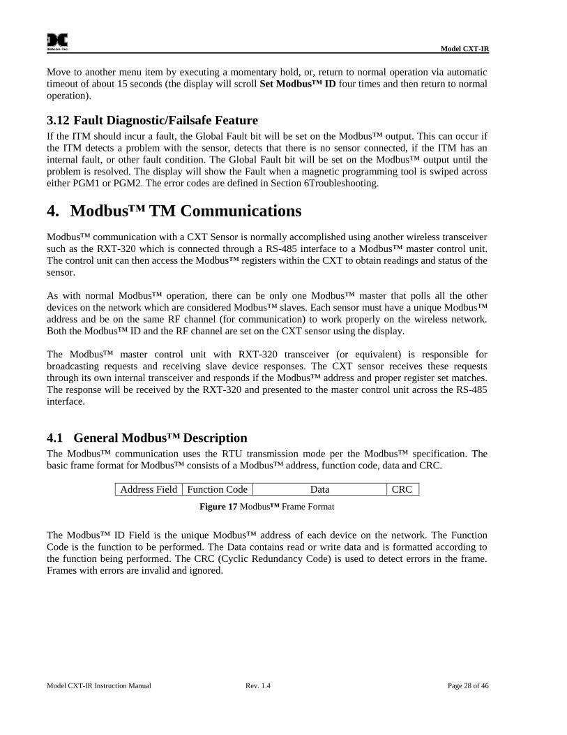
4.1 General Modbus™ DescriptionThe Modbus™ communication uses the RTU transmission mode per the Modbus™ specification. Thebasic frame format for Modbus™ consists of a Modbus™ address, function code, data and CRC.
Address Field Function Code Data CRC
Figure 17 Modbus™ Frame Format
The Modbus™ ID Field is the unique Modbus™ address of each device on the network. The FunctionCode is the function to be performed. The Data contains read or write data and is formatted according tothe function being performed. The CRC (Cyclic Redundancy Code) is used to detect errors in the frame.Frames with errors are invalid and ignored.
Model CXT-IR
Model CXT-IR Instruction Manual Rev. 1.4 Page 29 of 46
Modbus™ transactions consist of both a request by the controller and response from the device beingaddressed so there are two frames transferred for every transaction. Every request is evaluated by the CXTto determine if it is addressed to it, and if it falls within the register address range. If these two conditionsare true, the CXT will then check to see if it is a valid Function Code. Function Codes supported by theCXT are:
Function Code 03 (03h) – Read Holding Registers
Function Code 06 (06h) – Write Single Register
Function Code 16 (10h) – Write Multiple Registers
If an invalid function code is performed, the CXT will ignore the request by default and the controller willtimeout and continue with the next transaction.
4.1.1 Modbus™ Requests
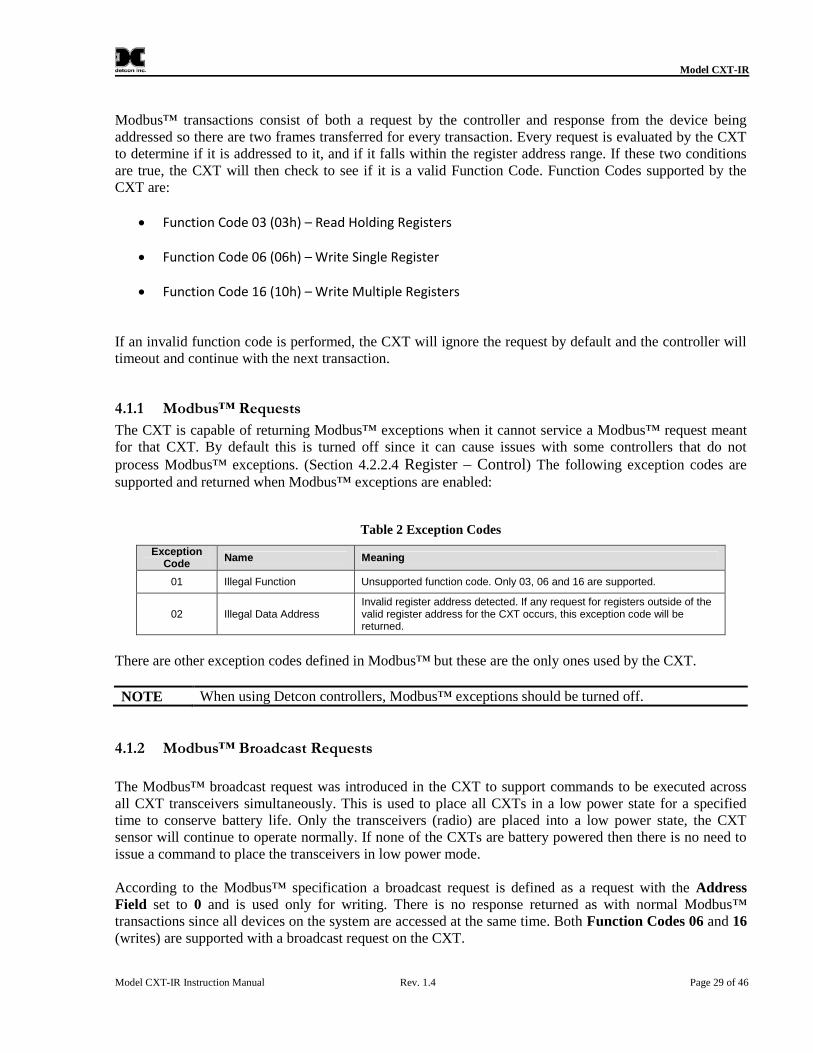
The CXT is capable of returning Modbus™ exceptions when it cannot service a Modbus™ request meantfor that CXT. By default this is turned off since it can cause issues with some controllers that do notprocess Modbus™ exceptions. (Section 4.2.2.4 Register – Control) The following exception codes aresupported and returned when Modbus™ exceptions are enabled:
Table 2 Exception Codes
ExceptionCode
Name Meaning
01 Illegal Function Unsupported function code. Only 03, 06 and 16 are supported.
02 Illegal Data AddressInvalid register address detected. If any request for registers outside of thevalid register address for the CXT occurs, this exception code will bereturned.
There are other exception codes defined in Modbus™ but these are the only ones used by the CXT.
NOTE When using Detcon controllers, Modbus™ exceptions should be turned off.
4.1.2 Modbus™ Broadcast Requests
The Modbus™ broadcast request was introduced in the CXT to support commands to be executed acrossall CXT transceivers simultaneously. This is used to place all CXTs in a low power state for a specifiedtime to conserve battery life. Only the transceivers (radio) are placed into a low power state, the CXTsensor will continue to operate normally. If none of the CXTs are battery powered then there is no need toissue a command to place the transceivers in low power mode.
According to the Modbus™ specification a broadcast request is defined as a request with the AddressField set to 0 and is used only for writing. There is no response returned as with normal Modbus™transactions since all devices on the system are accessed at the same time. Both Function Codes 06 and 16(writes) are supported with a broadcast request on the CXT.
Model CXT-IR
Model CXT-IR Instruction Manual Rev. 1.4 Page 30 of 46
Since there is no response on the broadcast request, there is a requirement to wait for a period of timebefore sending out the next request. This allows all slave devices to process the command before the nextrequest is received, also known as the turnaround delay. This turnaround delay should be approximately150 milliseconds for broadcast requests sent to the CXT. Controllers in general can meet this timingbecause it takes longer than this to generate the next request so it may be unnecessary to make anyadjustments.
NOTEControllers that generate Modbus™ broadcast requests to the CXT must ensure aturnaround delay of 150ms is met otherwise the next request can cause the broadcastrequest to be overwritten and ignored.
Broadcast requests are not confined to commands to put the network in low power mode, but can be usedwhere any normal write command is used.
4.2 Modbus™ Register Map and DirectionsWhen the CXT is assigned a Modbus™ address, the following registers become available to the controllerfor access. All CXT sensors implement this register set. Some registers are Read Only (R) and others areRead/Write (R/W) as shown by the R/W column. This equates to specific function codes where Read isfunction code 03 and Write is function code 06 or 16.
NOTEA write to a Read Only register is allowed and returns a response, but it does not change thevalue of the register. In some devices this would return an exception code.
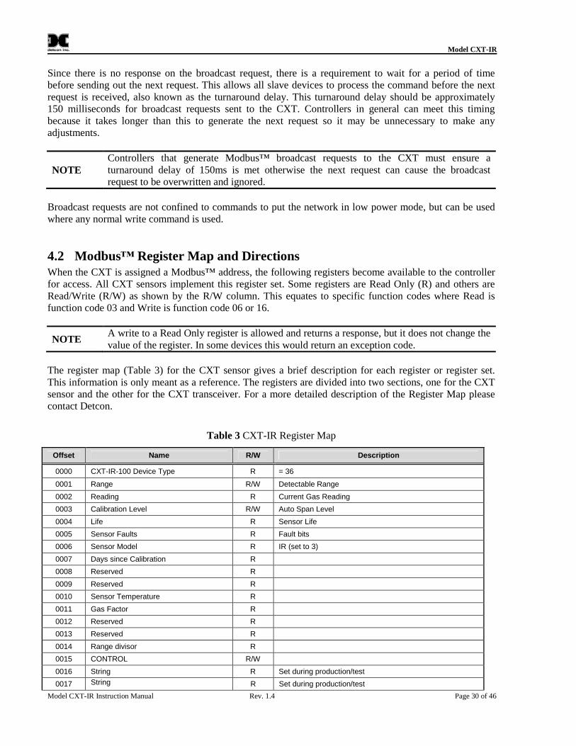
The register map (Table 3) for the CXT sensor gives a brief description for each register or register set.This information is only meant as a reference. The registers are divided into two sections, one for the CXTsensor and the other for the CXT transceiver. For a more detailed description of the Register Map pleasecontact Detcon.
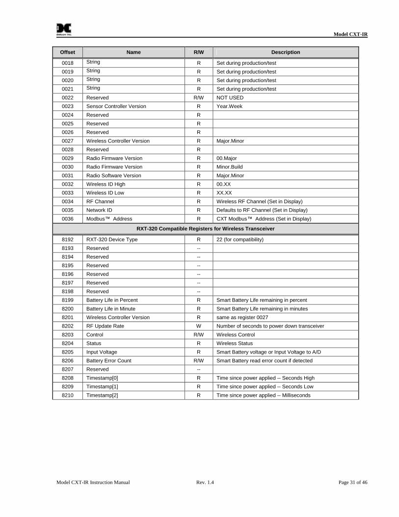
Table 3 CXT-IR Register Map
Offset Name R/W Description
0000 CXT-IR-100 Device Type R = 36
0001 Range R/W Detectable Range
0002 Reading R Current Gas Reading
0003 Calibration Level R/W Auto Span Level
0004 Life R Sensor Life
0005 Sensor Faults R Fault bits
0006 Sensor Model R IR (set to 3)
0007 Days since Calibration R
0008 Reserved R
0009 Reserved R
0010 Sensor Temperature R
0011 Gas Factor R
0012 Reserved R
0013 Reserved R
0014 Range divisor R
0015 CONTROL R/W
0016 String R Set during production/test
0017 String R Set during production/test
Model CXT-IR
Model CXT-IR Instruction Manual Rev. 1.4 Page 31 of 46
Offset Name R/W Description
0018 String R Set during production/test
0019 String R Set during production/test
0020 String R Set during production/test
0021 String R Set during production/test
0022 Reserved R/W NOT USED
0023 Sensor Controller Version R Year.Week
0024 Reserved R
0025 Reserved R
0026 Reserved R
0027 Wireless Controller Version R Major.Minor
0028 Reserved R
0029 Radio Firmware Version R 00.Major
0030 Radio Firmware Version R Minor.Build
0031 Radio Software Version R Major.Minor
0032 Wireless ID High R 00.XX
0033 Wireless ID Low R XX.XX
0034 RF Channel R Wireless RF Channel (Set in Display)
0035 Network ID R Defaults to RF Channel (Set in Display)
0036 Modbus™ Address R CXT Modbus™ Address (Set in Display)
RXT-320 Compatible Registers for Wireless Transceiver
8192 RXT-320 Device Type R 22 (for compatibility)
8193 Reserved --
8194 Reserved --
8195 Reserved --
8196 Reserved --
8197 Reserved --
8198 Reserved --
8199 Battery Life in Percent R Smart Battery Life remaining in percent
8200 Battery Life in Minute R Smart Battery Life remaining in minutes
8201 Wireless Controller Version R same as register 0027
8202 RF Update Rate W Number of seconds to power down transceiver
8203 Control R/W Wireless Control
8204 Status R Wireless Status
8205 Input Voltage R Smart Battery voltage or Input Voltage to A/D
8208 Timestamp[0] R Time since power applied -- Seconds High
8209 Timestamp[1] R Time since power applied -- Seconds Low
8210 Timestamp[2] R Time since power applied -- Milliseconds
Model CXT-IR
Model CXT-IR Instruction Manual Rev. 1.4 Page 32 of 46
4.2.1 CXT Sensor Registers
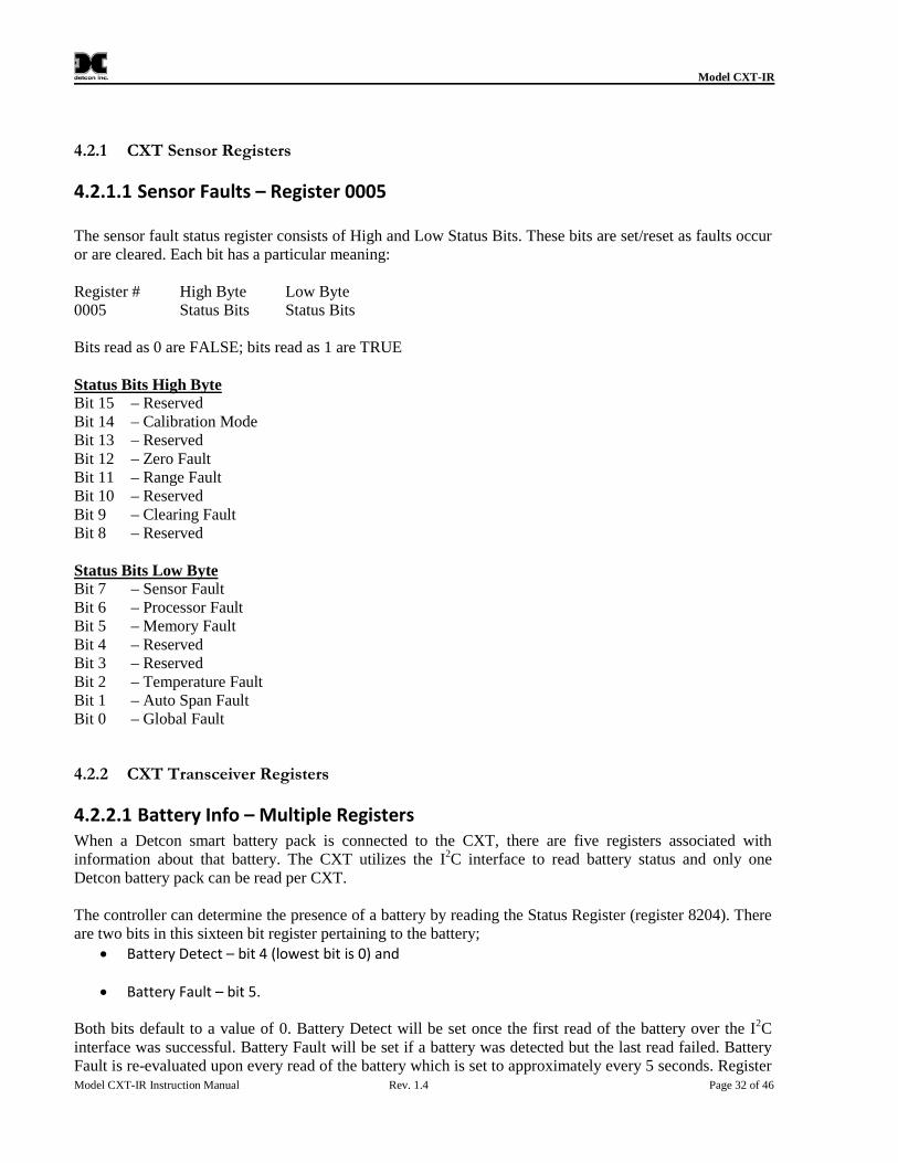
4.2.1.1 Sensor Faults – Register 0005
The sensor fault status register consists of High and Low Status Bits. These bits are set/reset as faults occuror are cleared. Each bit has a particular meaning:
Register # High Byte Low Byte0005 Status Bits Status Bits
Bits read as 0 are FALSE; bits read as 1 are TRUE
Status Bits High ByteBit 15 – ReservedBit 14 – Calibration ModeBit 13 – ReservedBit 12 – Zero FaultBit 11 – Range FaultBit 10 – ReservedBit 9 – Clearing FaultBit 8 – Reserved
Status Bits Low ByteBit 7 – Sensor FaultBit 6 – Processor FaultBit 5 – Memory FaultBit 4 – ReservedBit 3 – ReservedBit 2 – Temperature FaultBit 1 – Auto Span FaultBit 0 – Global Fault
4.2.2 CXT Transceiver Registers
4.2.2.1 Battery Info – Multiple RegistersWhen a Detcon smart battery pack is connected to the CXT, there are five registers associated withinformation about that battery. The CXT utilizes the I2C interface to read battery status and only oneDetcon battery pack can be read per CXT.
The controller can determine the presence of a battery by reading the Status Register (register 8204). Thereare two bits in this sixteen bit register pertaining to the battery;
Battery Detect – bit 4 (lowest bit is 0) and
Battery Fault – bit 5.
Both bits default to a value of 0. Battery Detect will be set once the first read of the battery over the I2Cinterface was successful. Battery Fault will be set if a battery was detected but the last read failed. BatteryFault is re-evaluated upon every read of the battery which is set to approximately every 5 seconds. Register
Model CXT-IR
Model CXT-IR Instruction Manual Rev. 1.4 Page 33 of 46
8206 (I2C Batt Read Fails) will increment by four each time there is a failure since there are four attemptsbefore declaring failure. This register can be cleared by writing a 0 to it at any point.
Once the battery has been detected the controller can read the battery life (registers 8199 and 8200). Thebattery adjusts these values based upon the average current usage. If usage varies widely over time it willtake some time to re-adjust the battery life readings. For example, an alarm station with no alarms willconsume a very small amount of battery but when alarms are active this will jump to a much higher level ofusage. So in this case battery life may go from several weeks down to several hours.
The battery life is presented in two forms, life remaining in percentage (register 8199) and life remaining inminutes (register 8200). The battery life remaining (%) is a value between 0 and 100 and battery life inminutes is an unsigned value between 0 and 65535. Both readings are generally necessary to provideappropriate feedback to the user. Life in minutes is the best for determining when to change the battery. Forexample, to be notified a day before the battery needs to be changed, set a threshold in the controller to benotified of low battery after 1440 minutes (1 day).
The maximum value for life remaining in minutes is 65535 (45.5 days). The battery life for an applicationcan be much greater than the maximum value and the reading will remain at 65535 until it drops below themaximum value. Life in percentage provides a more efficient tracking method. Percentage will trackstarting at 100% and drop down as the battery life decreases. The controller can therefore use bothregisters, one to represent usage in percentage to present to the user and then use the life in minutes to set athreshold on when a low battery condition exists for changing the battery.
4.2.2.2 Wireless Controller VersionThis is set to a value based upon the version of firmware programmed into the RXT-320 microcontroller. Itis stored as two byte value representing the major and minor revision numbers. So a 0113h (275 decimal)represents a major version of 01 and minor version of 13. As software is updated this will be incrementedappropriately.
4.2.2.3 Register – Update RateThe update rate represents the amount of time in seconds the CXT transceiver will be in a low power state.Its main purpose is to provide a mechanism to place all wireless transceivers in a system into a low powermode to conserve battery power. If there are no batteries used within the network of wireless transceiversthis register would not be utilized.
Upon power up, this register is set to 0 and the CXT transceiver is not in low power mode. To place anetwork to low power mode the controller will generate a broadcast request (Modbus™ address = 0) and doa single write (function code 06) to register 8202 with the number of seconds the network should go intolow power mode. During low power mode, there can be no access to any device on the network so changesin sensor readings will not be updated. Once a non-zero value is written to this register on all transceivers,they will begin counting down until the Update Rate register reaches zero, at which time all transceiversshould be active again and ready for network communication. The controller will monitor the update ratetime remaining by accessing Update Rate register on the RXT-320 (or equivalent) that it is attached. TheModbus™ interface remains active, only the wireless network is placed in a low power state. The value ofthis register can be between 0 and 65535 which allows a maximum low power time of 18.2 hours. Removalof power will reset Update Rate to 0 and the transceiver will be active again.
Model CXT-IR
Model CXT-IR Instruction Manual Rev. 1.4 Page 34 of 46
4.2.2.4 Register – ControlThe CXT transceiver control register is generally unused and should not be written to normally. Using thecontrol register, the CXT can be reset and Modbus™ exceptions can be enabled. Each bit in the controlregister can control a particular function and should be read first then modify the bits needed and writtenback. The default state of the register is 0. All reserved bits should always be set to a 0 when writing.
The bit assignments are:
Bit 15: Reserved (set to 0)Bit 14: Reserved (set to 0)Bit 13 – 12: Reserved (set to 0)Bit 11: Modbus™ Exceptions EnabledBit 10 – 08: Reserved (set to 0)Bit 07: Reset the microcontroller and wireless radioBit 06: Reset the microcontrollerBit 05 – 00: Reserved (set to 0)
4.2.2.5 Register – StatusThis register contains status of the CXT transceiver and some of the bits have already been covered in thebattery description. These default to 0 upon reset. The bit assignment and description are given below.
Bit 15 – 08: Reserved (set to 0)Bit 07: Reserved (set to 0)Bit 06: Reserved (set to 1)Bit 05: I2C Fault on last read of Battery StatusBit 04: Battery DetectedBit 03: Reserved (set to 0)Bit 02: Reserved (set to 1)Bit 01: Reserved (set to 0)Bit 00: Reserved (set to 0)
4.2.2.6 Register – TimestampThree registers are utilized to maintain a timestamp that increments on the microcontroller after power up.These are all set to 0 upon power up or a microcontroller reset. The first two registers 8208 and 8209 areinternally combined into a single 32 bit register and incremented each second. The last register 8210maintains the millisecond count and will count from 0 to 999 and start over again.
5. Service and Maintenance
5.1 Calibration FrequencyIn most applications, monthly to quarterly span calibration intervals will assure reliable detection. Uponinitial installation and commissioning, close frequency tests should be performed, weekly to monthly. Testresults should be recorded and reviewed to determine a suitable calibration interval due to differences inindustrial environments.
Model CXT-IR
Model CXT-IR Instruction Manual Rev. 1.4 Page 35 of 46
5.2 Visual InspectionThe Sensor should be inspected annually for the following:
Inspect the sensor for signs of corrosion, pitting, and water damage.
Remove the Splash Guard and inspected it for blockage, broken, cracked, or missing pieces.
For H2S Sensor assemblies, inspect CXT-IR Series Splashguard Adapter Assembly with integral
filter (PN 602-003552-100) for blockage of filter material.
Inspect inside of the Junction Box for signs of water accumulation, signs of corrosion.
Check wiring to ensure there are no loose or pinched wires and all connections are clean and
tight.
5.3 Condensation Prevention PacketA moisture condensation packet (Detcon PN 960-202200-000) should be installed in every explosion proofJunction Box. The moisture condensation prevention packet will prevent the internal volume of the J-Boxfrom condensing and accumulating moisture due to day-night humidity changes. This packet provides acritical function and should be replaced annually.
5.4 Replacement of the Batteries/Battery Pack
5.4.1 Low Battery Fault Indication
The CXT-IR Sensor incorporates a ‘Low battery’ fault message which will appear as an alternating displaybetween the current gas reading and ‘VOLT’ on the sensor display. This fault will appear when the batteryvoltage drops below 7.5 volts. When the voltages drops below 7.2 volts the display will change to a steady‘VOLT’ display, the sensor will then enter into ‘Fault’ mode, and the sensor will no longer provide a validgas reading.
5.4.2 Units with 12V Smart Battery Pack
NOTEThe safety approvals require removing entire sensor assembly to a non-hazardous areabefore changing out the batteries or battery pack.
1. Remove the cover from the J-box.2. Unlatch the holding lever on the side of the battery bracket, and swing the cover away from the
battery pack.3. Remove the battery pack from the J-box, and replace with new battery pack.4. Swing the cover back over the battery pack, and ensure that it is latched.5. Replace the cover on the J-box.
5.4.3 Units with Tri-C sized Lithium Battery Holder
NOTEThe safety approvals require removing entire sensor assembly to a non-hazardous areabefore changing out the batteries or battery pack.
Model CXT-IR
Model CXT-IR Instruction Manual Rev. 1.4 Page 36 of 46
1. Remove the cover from the J-box.2. Press Tri-C Battery Holder down to disengage latch and rotate counter-clockwise according to
instructions on lid to remove from Enclosure Base. Lift Battery Holder from Enclosure Base3. Unscrew the cover on the battery holder. Orientation of batteries marked inside cover and holder4. Remove the batteries from the battery holder.5. Replace the batteries with the same type (Detcon PN 360-026500-000). Do NOT use regular ꞌCꞌ
size batteries, as this may cause damage to the sensor assembly.6. Pay attention to the orientation of the batteries when installing in Battery Holder.7. Reattach the battery cover using screws.8. Re-install Tri-C Battery Holder in Enclosure Base, pressing down and rotating clockwise to secure.9. Replace the cover on the J-box
5.5 Replacement of Plug-in Sensor
NOTEIt is not necessary to remove power while changing the plug-in combustible gas sensor inorder to maintain area classification, since it is intrinsically safe.
NOTE Only replace the plug-in sensor with an authorized CXT-IR family of gas sensors.
ITM(Bottom View)
DisplayWindow
Plug in Sensor(Bottom view)
LockingSetscrew
LockingSetscrew
detcon inc.
MODELCXT-IR
Figure 18 Sensor Cell and ITM Mating
1. Use a 1/16" Allen wrench to release the locking setscrew that locks the ITM and splashguard adapterassembly together (One turn only - Do not remove setscrew completely).
2. Remove the splashguard.3. Unthread and remove the splashguard adapter assembly from the ITM.4. Gently pull the plug-in sensor out of the ITM. Verify the gas type and range of the new sensor cell
is correct.5. Orient the new plug-in sensor so that it matches with the female connector pins. When properly
aligned, press the sensor in firmly to make the proper connection.6. Thread the splashguard adapter assembly onto the ITM to a snug fit and tighten the locking
setscrew using the 1/16" Allen wrench.
Model CXT-IR
Model CXT-IR Instruction Manual Rev. 1.4 Page 37 of 46
7. Install the splashguard.8. Check and perform zero calibration and span calibration as per Section 3.3.
5.6 Replacement of ITM – Aluminum Junction Box1. Remove the power source to the sensor assembly.
2. Remove the battery pack from the J-box.
3. Disconnect all sensor wire connections at the Junction Box Terminal Board, taking note of the wireconnections, and disconnect the RF cable connector.
NOTEIt is necessary to remove power to the Junction box while changing the ITM in order tomaintain area classification.
4. Use a wrench and the wrench flats provided at the top section of the ITM and unthread the ITM forremoval.
5. Use a 1/8" Allen wrench to release the locking cap head screw that locks the ITM and splashguardadapter assembly together (One turn only - Do not remove setscrew completely).
6. Unthread and remove the splashguard adapter assembly and splashguard from the ITM. These willbe re-used with the new ITM.
7. Gently remove the plug-in combustible gas sensor from the old ITM and install it in the new ITM.Orient the plug-in sensor pins so that it matches the female connector pins on the new ITM thenpress the sensor in firmly to make proper connection.
8. Thread the splashguard adapter assembly onto the new ITM until snug, tighten the locking caphead screw and reinstall splashguard.
9. Feed the sensor assembly wires and RF cable through the 3/4" female NPT port and thread theassembly into the J-box until tight and the ITM faces toward the front access point. Use the lockingnut to secure the ITM in this position.
10. Re-connect the sensor assembly wires to the terminal board inside the Junction Box.
11. Re-connect the RF cable to the antenna cable.
12. Install the battery pack.
13. Check and/or perform Zero Calibration and Span Calibration in accordance with Section 3.3.
5.7 Replacement of ITM – Stainless Steel Mini Condulet1. Remove the cover of the battery holder, and remove the batteries.2. Remove the battery holder from the J-box by removing the two 6-32 screws at the bottom of the
housing.
NOTEIt is necessary to remove power to the Junction box while changing the ITM in order tomaintain area classification.
Model CXT-IR
Model CXT-IR Instruction Manual Rev. 1.4 Page 38 of 46
3. Disconnect the sensor wire connections from the shorting blocks, taking note of the wireconnections.
4. Disconnect the RF cable connector. (The wire splice shorting blocks can be difficult to removewires from. By using a pair of needle nose pliers and twisting the wires while pulling them out ofthe shorting blocks can make the task easier.)
5. Use a wrench and the wrench flats provided at the top section of the ITM and unthread the ITMuntil it can be removed.
6. Use a 1/8" Allen wrench to release the locking cap head screw that locks the ITM and SplashguardAdapter Assembly together (One turn only - Do not remove setscrew completely).
7. Unthread and remove the splashguard adapter assembly and splashguard from the ITM. These willbe re-used with the new ITM.
8. Gently remove the plug-in combustible gas sensor from the old ITM and install it in the new ITM.Orient the plug-in sensor pins so that it matches the female connector pins on the new ITM thenpress the sensor in firmly to make proper connection.
9. Thread the splashguard adapter assembly onto the new ITM until snug, tighten the locking caphead screw and reinstall splashguard.
10. Feed the sensor assembly wires and RF cable through the 3/4" female NPT port and thread theassembly into the J-box until tight and the ITM faces toward the front access point. Use the lockingnut to secure the ITM in this position.
11. Re-connect the sensor assembly wires to the shorting blocks by pushing the wire straight into theblock board inside the Junction Box. (Red to red, and black to black.)
12. Re-connect the RF cable to the antenna cable.
13. Install the battery holder in the J-box.
14. Install the batteries into the housing.
15. Replace the battery holder cover.
16. Check and/or perform Zero Calibration and Span Calibration per Section 3.3.
6. Troubleshooting Guide
If the ITM detects any functional errors the ITM will display the fault. If the sensor is experiencing a faultcondition a momentary swipe of the magnet will cause the ITM to scroll the fault condition(s) across thedisplay before the ◄ or ► prompt will appear.
Model CXT-IR Instruction Manual Rev. 1.4 Page 39 of 46
Range FaultMissing Sensor Cell FaultSensor FaultZero FaultLow Battery Fault
Some faults are self-explanatory, and if these faults occur and cannot be cleared the ITM should bereplaced first to see if the fault will clear. Other faults may need further investigation. Some of the sensorproblems, associated error codes, and resolutions are listed below.
6.1 Missing Sensor Cell Fault
Probable Cause: The sensor cell is not installed, is installed incorrectly, or is non operational.
Replace the Sensor Cell with a known good Sensor Cell.
6.2 Sensor Fault
Probable Cause: The sensor optics have become too dirty to support functionality.
Replace the Sensor Cell with a known good Sensor Cell.
All Technical Service and Repair activities should be handled by the Detcon Service Department by phone,fax or email through the contact information given above. RMA numbers should be obtained from theDetcon Service Department prior to equipment being returned. For on-line technical service, customersshould have ready the model number, part number, and serial number of product(s) in question.
All Sales activities (including spare parts purchase) should be handled by the Detcon Sales Department viaphone, fax or email at contact information given above.
7.1 Warranty NoticeDetcon Inc. warrants the Model CXT-IR gas sensor to be free from defects in workmanship of materialunder normal use and service for one year from the date of shipment on the transmitter electronics. SeeWarranty details in Section 7.2.
Detcon Inc. will repair or replace without charge any such equipment found to be defective during thewarranty period. Full determination of the nature of, and responsibility for, defective or damagedequipment will be made by Detcon Inc. personnel.
Defective or damaged equipment must be shipped to the Detcon Inc. factory or representative from whichthe original shipment was made. In all cases, this warranty is limited to the cost of the equipment suppliedby Detcon Inc. The customer will assume all liability for the misuse of this equipment by its employees orother contracted personnel.
All warranties are contingent upon the proper use in the application for which the product was intended anddoes not cover products which have been modified or repaired without Detcon Inc. approval, or which havebeen subjected to neglect, accident, improper installation or application, or on which the originalidentification marks have been removed or altered.
Except for the express warranty stated above, Detcon Inc. disclaims all warranties with regard to theproducts sold. Including all implied warranties of merchantability and fitness and the express warrantiesstated herein are in lieu of all obligations or liabilities on the part of Detcon Inc. for damages including, butnot limited to, consequential damages arising out of, or in connection with, the performance of the product.
Model CXT-IR
Model CXT-IR Instruction Manual Rev. 1.4 Page 44 of 46
7.2 CXT-IR Sensor WarrantyDetcon, Inc., as the manufacturer, warrants under intended normal use each new CXT-IR sensor to be freefrom defects in material and workmanship for a period of one year from the date of shipment to the originalpurchaser. Should the sensor fail to perform in accordance with published specifications within thewarranty period, return to Detcon, Inc., for necessary repair or replacement. All warranties and servicepolicies are FOB the Detcon facility located in The Woodlands, Texas.
7.2.1 Terms and Conditions
The original serial number must be legible on each sensor element base.
Shipping point is FOB the Detcon factory.
Net payment is due within 30 days of invoice.
Detcon, Inc. reserves the right to refund the original purchase price in lieu of sensor
replacement.
Model CXT-IR
Model CXT-IR Instruction Manual Rev. 1.4 Page 45 of 46
8. Appendix
8.1 Specifications
8.1.1 System Specifications
Sensor Type: Continuous diffusion/adsorption typeNDIR Non-Disperse InfraredSub-miniature plug-in replaceable type
Sensor Life: 5 years typical
Measuring Ranges: 0-100% LEL, 0-100% by volume
Accuracy/ Repeatability: ± 3% LEL in 0-50% LEL range, ± 5% LEL in 51-100% LEL range
Response Time: T50 < 10 seconds, T90 < 30 seconds
Warranty: 1 year
8.1.2 Environmental Specifications
Operating Temperature: -40°C to +75°C
Storage Temperature: -40°C to +75°C
Operating Humidity: 0-100% RH (Non-condensing)
Operating Pressure: ±10% atmospheric pressure
8.1.3 Electrical Specifications
Input Voltage: 6-30VDC
Power Consumption: 25mW (typical), 420mW (max)
RFI/EMI Protection: Complies with EN61326
8.1.4 Mechanical Specifications
Length: 14.4 inches (365mm), includes splashguard
Width: 3.77 inches (96mm)
Weight: 5.5lbs (2.5kg), without batteries
Model CXT-IR
Model CXT-IR Instruction Manual Rev. 1.4 Page 46 of 46