Commander 400 OPERATOR’S MANUAL IM544-B June, 1998 Safety Depends on You Lincoln arc welding and cutting equipment is designed and built with safety in mind. However, your overall safety can be increased by proper installation ... and thoughtful operation on your part. DO NOT INSTALL, OPERATE OR REPAIR THIS EQUIPMENT WITHOUT READING THIS MANUAL AND THE SAFETY PRECAUTIONS CONTAINED THROUGHOUT. And, most importantly, think before you act and be careful. For use with machines having Code Numbers: 9978, 10580 (Stick Model), 9979, 10581 (Stick and Wire Model) ™ • Sales and Service through Subsidiaries and Distributors Worldwide • Cleveland, Ohio 44117-1199 U.S.A. TEL: 216.481.8100 FAX: 216.486.1751 WEB SITE: www.lincolnelectric.com World's Leader in Welding and Cutting Products Premier Manufacturer of Industrial Motors
Transcript
Commander 400
OPERATOR’S MANUAL
IM544-BJune, 1998
Safety Depends on YouLincoln arc welding and cuttingequipment is designed and builtwith safety in mind. However, youroverall safety can be increased byproper installation ... and thoughtfuloperation on your part. DO NOTINSTALL, OPERATE OR REPAIRTHIS EQUIPMENT WITHOUTREADING THIS MANUAL ANDTHE SAFETY PRECAUTIONSCONTAINED THROUGHOUT. And,most importantly, think before youact and be careful.
For use with machines having Code Numbers: 9978, 10580 (Stick Model),9979, 10581 (Stick and Wire Model)
™
• Sales and Service through Subsidiaries and Distributors Worldwide •Cleveland, Ohio 44117-1199 U.S.A. TEL: 216.481.8100 FAX: 216.486.1751 WEB SITE: www.lincolnelectric.com
World's Leader in Welding and Cutting Products Premier Manufacturer of Industrial Motors
FOR ENGINEpowered equipment.
1.a. Turn the engine off before troubleshooting and maintenancework unless the maintenance work requires it to be running.
____________________________________________________1.b.Operate engines in open, well-ventilated
areas or vent the engine exhaust fumes outdoors.
____________________________________________________1.c. Do not add the fuel near an open flame weld-
ing arc or when the engine is running. Stopthe engine and allow it to cool before refuel-ing to prevent spilled fuel from vaporizing oncontact with hot engine parts and igniting. Donot spill fuel when filling tank. If fuel is spilled,wipe it up and do not start engine until fumeshave been eliminated.
____________________________________________________1.d. Keep all equipment safety guards, coversand devices in posi-
tion and in good repair.Keep hands, hair, clothing and toolsaway from V-belts, gears, fans and all other moving partswhen starting, operating or repairing equipment.
1.e. In some cases it may be necessary to remove safetyguards to perform required maintenance. Removeguards only when necessary and replace them when themaintenance requiring their removal is complete.Always use the greatest care when working near movingparts.
___________________________________________________1.f. Do not put your hands near the engine fan. Do
not attempt to override the governor or idlerby pushing on the throttle control rods whilethe engine is running.
___________________________________________________1.g. To prevent accidentally starting gasoline engines while
turning the engine or welding generator during maintenancework, disconnect the spark plug wires, distributor cap ormagneto wire as appropriate.
iSAFETYi
ARC WELDING CAN BE HAZARDOUS. PROTECT YOURSELF AND OTHERS FROM POSSIBLE SERIOUS INJURY OR DEATH.KEEP CHILDREN AWAY. PACEMAKER WEARERS SHOULD CONSULT WITH THEIR DOCTOR BEFORE OPERATING.
Read and understand the following safety highlights. For additional safety information, it is strongly recommended that you pur-chase a copy of “Safety in Welding & Cutting - ANSI Standard Z49.1” from the American Welding Society, P.O. Box 351040,Miami, Florida 33135 or CSA Standard W117.2-1974. A Free copy of “Arc Welding Safety” booklet E205 is available from theLincoln Electric Company, 22801 St. Clair Avenue, Cleveland, Ohio 44117-1199.
BE SURE THAT ALL INSTALLATION, OPERATION, MAINTENANCE AND REPAIR PROCEDURES AREPERFORMED ONLY BY QUALIFIED INDIVIDUALS.
WARNING
Mar ‘95
ELECTRIC AND MAGNETIC FIELDSmay be dangerous
2.a. Electric current flowing through any conductor causes localized Electric and Magnetic Fields (EMF). Welding current creates EMF fields around welding cables and welding machines
2.b. EMF fields may interfere with some pacemakers, andwelders having a pacemaker should consult their physicianbefore welding.
2.c. Exposure to EMF fields in welding may have other healtheffects which are now not known.
2.d. All welders should use the following procedures in order tominimize exposure to EMF fields from the welding circuit:
2.d.1. Route the electrode and work cables together - Securethem with tape when possible.
2.d.2. Never coil the electrode lead around your body.
2.d.3. Do not place your body between the electrode andwork cables. If the electrode cable is on your right side, the work cable should also be on your right side.
2.d.4. Connect the work cable to the workpiece as close aspossible to the area being welded.
2.d.5. Do not work next to welding power source.
1.h. To avoid scalding, do not remove theradiator pressure cap when the engine ishot.
For Diesel Engines: Diesel engine exhaust andsome of its constituents are known to the Stateof California to cause cancer, birth defects, andother reproductive harm.
For Gasoline Engines: The engine exhaust fromthis product contains chemicals known to theState of California to cause cancer, birth defects,or other reproductive harm.
CALIFORNIA PROPOSITION 65 WARNINGS
iiSAFETYii
ARC RAYS can burn.4.a. Use a shield with the proper filter and cover
plates to protect your eyes from sparks andthe rays of the arc when welding or observingopen arc welding. Headshield and filter lensshould conform to ANSI Z87. I standards.
4.b. Use suitable clothing made from durable flame-resistantmaterial to protect your skin and that of your helpers fromthe arc rays.
4.c. Protect other nearby personnel with suitable, non-flammablescreening and/or warn them not to watch the arc nor exposethemselves to the arc rays or to hot spatter or metal.
ELECTRIC SHOCK can kill.3.a. The electrode and work (or ground) circuits
are electrically “hot” when the welder is on.Do not touch these “hot” parts with your bareskin or wet clothing. Wear dry, hole-freegloves to insulate hands.
3.b. Insulate yourself from work and ground using dry insulation.Make certain the insulation is large enough to cover your fullarea of physical contact with work and ground.
In addition to the normal safety precautions, if weldingmust be performed under electrically hazardousconditions (in damp locations or while wearing wetclothing; on metal structures such as floors, gratings orscaffolds; when in cramped positions such as sitting,kneeling or lying, if there is a high risk of unavoidable oraccidental contact with the workpiece or ground) usethe following equipment:
• Semiautomatic DC Constant Voltage (Wire) Welder.• DC Manual (Stick) Welder.• AC Welder with Reduced Voltage Control.
3.c. In semiautomatic or automatic wire welding, the electrode,electrode reel, welding head, nozzle or semiautomaticwelding gun are also electrically “hot”.
3.d. Always be sure the work cable makes a good electricalconnection with the metal being welded. The connectionshould be as close as possible to the area being welded.
3.e. Ground the work or metal to be welded to a good electrical(earth) ground.
3.f. Maintain the electrode holder, work clamp, welding cable andwelding machine in good, safe operating condition. Replacedamaged insulation.
3.g. Never dip the electrode in water for cooling.
3.h. Never simultaneously touch electrically “hot” parts ofelectrode holders connected to two welders because voltagebetween the two can be the total of the open circuit voltageof both welders.
3.i. When working above floor level, use a safety belt to protectyourself from a fall should you get a shock.
3.j. Also see Items 6.c. and 8.
FUMES AND GASEScan be dangerous.5.a. Welding may produce fumes and gases
hazardous to health. Avoid breathing thesefumes and gases.When welding, keepyour head out of the fume. Use enoughventilation and/or exhaust at the arc to keep
fumes and gases away from the breathing zone. Whenwelding with electrodes which require specialventilation such as stainless or hard facing (seeinstructions on container or MSDS) or on lead orcadmium plated steel and other metals or coatingswhich produce highly toxic fumes, keep exposure aslow as possible and below Threshold Limit Values (TLV)using local exhaust or mechanical ventilation. Inconfined spaces or in some circumstances, outdoors, arespirator may be required. Additional precautions arealso required when welding on galvanized steel.
5.b. Do not weld in locations near chlorinated hydrocarbon vaporscoming from degreasing, cleaning or spraying operations.The heat and rays of the arc can react with solvent vapors toform phosgene, a highly toxic gas, and other irritating products.
5.c. Shielding gases used for arc welding can displace air andcause injury or death. Always use enough ventilation,especially in confined areas, to insure breathing air is safe.
5.d. Read and understand the manufacturer’s instructions for thisequipment and the consumables to be used, including thematerial safety data sheet (MSDS) and follow youremployer’s safety practices. MSDS forms are available fromyour welding distributor or from the manufacturer.
5.e. Also see item 1.b. Mar ‘95
FOR ELECTRICALLYpowered equipment.
8.a. Turn off input power using the disconnectswitch at the fuse box before working onthe equipment.
8.b. Install equipment in accordance with the U.S. NationalElectrical Code, all local codes and the manufacturer’srecommendations.
8.c. Ground the equipment in accordance with the U.S. NationalElectrical Code and the manufacturer’s recommendations.
CYLINDER may explodeif damaged.7.a. Use only compressed gas cylinders
containing the correct shielding gas for theprocess used and properly operatingregulators designed for the gas and
pressure used. All hoses, fittings, etc. should be suitable forthe application and maintained in good condition.
7.b. Always keep cylinders in an upright position securelychained to an undercarriage or fixed support.
7.c. Cylinders should be located:• Away from areas where they may be struck or subjected tophysical damage.
• A safe distance from arc welding or cutting operations andany other source of heat, sparks, or flame.
7.d. Never allow the electrode, electrode holder or any otherelectrically “hot” parts to touch a cylinder.
7.e. Keep your head and face away from the cylinder valve outletwhen opening the cylinder valve.
7.f. Valve protection caps should always be in place and handtight except when the cylinder is in use or connected foruse.
7.g. Read and follow the instructions on compressed gascylinders, associated equipment, and CGA publication P-l,“Precautions for Safe Handling of Compressed Gases inCylinders,” available from the Compressed Gas Association1235 Jefferson Davis Highway, Arlington, VA 22202.
iiiSAFETYiii
Mar ‘95
WELDING SPARKS cancause fire or explosion.6.a. Remove fire hazards from the welding area.
If this is not possible, cover them to preventthe welding sparks from starting a fire.Remember that welding sparks and hot
materials from welding can easily go through small cracksand openings to adjacent areas. Avoid welding nearhydraulic lines. Have a fire extinguisher readily available.
6.b. Where compressed gases are to be used at the job site,special precautions should be used to prevent hazardoussituations. Refer to “Safety in Welding and Cutting” (ANSIStandard Z49.1) and the operating information for theequipment being used.
6.c. When not welding, make certain no part of the electrodecircuit is touching the work or ground. Accidental contact cancause overheating and create a fire hazard.
6.d. Do not heat, cut or weld tanks, drums or containers until theproper steps have been taken to insure that such procedureswill not cause flammable or toxic vapors from substancesinside. They can cause an explosion even though they havebeen “cleaned”. For information, purchase “RecommendedSafe Practices for the Preparation for Welding and Cutting ofContainers and Piping That Have Held HazardousSubstances”, AWS F4.1 from the American Welding Society(see address above).
6.e. Vent hollow castings or containers before heating, cutting orwelding. They may explode.
6.f. Sparks and spatter are thrown from the welding arc. Wear oilfree protective garments such as leather gloves, heavy shirt,cuffless trousers, high shoes and a cap over your hair. Wearear plugs when welding out of position or in confined places.Always wear safety glasses with side shields when in awelding area.
6.g. Connect the work cable to the work as close to the weldingarea as practical. Work cables connected to the buildingframework or other locations away from the welding areaincrease the possibility of the welding current passingthrough lifting chains, crane cables or other alternate circuits.This can create fire hazards or overheat lifting chains orcables until they fail.
6.h. Also see item 1.c.
ivSAFETYiv
PRÉCAUTIONS DE SÛRETÉPour votre propre protection lire et observer toutes les instructionset les précautions de sûreté specifiques qui parraissent dans cemanuel aussi bien que les précautions de sûreté générales suiv-antes:
Sûreté Pour Soudage A L’Arc1. Protegez-vous contre la secousse électrique:
a. Les circuits à l’électrode et à la piéce sont sous tensionquand la machine à souder est en marche. Eviter toujourstout contact entre les parties sous tension et la peau nueou les vétements mouillés. Porter des gants secs et sanstrous pour isoler les mains.
b. Faire trés attention de bien s’isoler de la masse quand onsoude dans des endroits humides, ou sur un plancher met-allique ou des grilles metalliques, principalement dans les positions assis ou couché pour lesquelles une grandepartie du corps peut être en contact avec la masse.
c. Maintenir le porte-électrode, la pince de masse, le câble desoudage et la machine à souder en bon et sûr état defonc-tionnement.
d.Ne jamais plonger le porte-électrode dans l’eau pour lerefroidir.
e. Ne jamais toucher simultanément les parties sous tensiondes porte-électrodes connectés à deux machines à soud-er parce que la tension entre les deux pinces peut être letotal de la tension à vide des deux machines.
f. Si on utilise la machine à souder comme une source decourant pour soudage semi-automatique, ces precautionspour le porte-électrode s’applicuent aussi au pistolet desoudage.
2. Dans le cas de travail au dessus du niveau du sol, se protégercontre les chutes dans le cas ou on recoit un choc. Ne jamaisenrouler le câble-électrode autour de n’importe quelle partiedu corps.
3. Un coup d’arc peut être plus sévère qu’un coup de soliel,donc:
a. Utiliser un bon masque avec un verre filtrant appropriéainsi qu’un verre blanc afin de se protéger les yeux du ray-onnement de l’arc et des projections quand on soude ouquand on regarde l’arc.
b. Porter des vêtements convenables afin de protéger la peaude soudeur et des aides contre le rayonnement de l‘arc.
c. Protéger l’autre personnel travaillant à proximité ausoudage à l’aide d’écrans appropriés et non-inflammables.
4. Des gouttes de laitier en fusion sont émises de l’arc desoudage. Se protéger avec des vêtements de protection libresde l’huile, tels que les gants en cuir, chemise épaisse, pan-talons sans revers, et chaussures montantes.
5. Toujours porter des lunettes de sécurité dans la zone desoudage. Utiliser des lunettes avec écrans lateraux dans leszones où l’on pique le laitier.
6. Eloigner les matériaux inflammables ou les recouvrir afin deprévenir tout risque d’incendie dû aux étincelles.
7. Quand on ne soude pas, poser la pince à une endroit isolé dela masse. Un court-circuit accidental peut provoquer unéchauffement et un risque d’incendie.
8. S’assurer que la masse est connectée le plus prés possible dela zone de travail qu’il est pratique de le faire. Si on place lamasse sur la charpente de la construction ou d’autres endroitséloignés de la zone de travail, on augmente le risque de voirpasser le courant de soudage par les chaines de levage,câbles de grue, ou autres circuits. Cela peut provoquer desrisques d’incendie ou d’echauffement des chaines et descâbles jusqu’à ce qu’ils se rompent.
9. Assurer une ventilation suffisante dans la zone de soudage.Ceci est particuliérement important pour le soudage de tôlesgalvanisées plombées, ou cadmiées ou tout autre métal quiproduit des fumeés toxiques.
10. Ne pas souder en présence de vapeurs de chlore provenantd’opérations de dégraissage, nettoyage ou pistolage. Lachaleur ou les rayons de l’arc peuvent réagir avec les vapeursdu solvant pour produire du phosgéne (gas fortement toxique)ou autres produits irritants.
11. Pour obtenir de plus amples renseignements sur la sûreté, voirle code “Code for safety in welding and cutting” CSA StandardW 117.2-1974.
PRÉCAUTIONS DE SÛRETÉ POURLES MACHINES À SOUDER ÀTRANSFORMATEUR ET ÀREDRESSEUR
1. Relier à la terre le chassis du poste conformement au code del’électricité et aux recommendations du fabricant. Le dispositifde montage ou la piece à souder doit être branché à unebonne mise à la terre.
2. Autant que possible, I’installation et l’entretien du poste seronteffectués par un électricien qualifié.
3. Avant de faires des travaux à l’interieur de poste, la debranch-er à l’interrupteur à la boite de fusibles.
4. Garder tous les couvercles et dispositifs de sûreté à leurplace.
Mar. ‘93
Thank You for selecting a QUALITY product by Lincoln Electric. We want youto take pride in operating this Lincoln Electric Company product •••as much pride as we have in bringing this product to you!
Read this Operators Manual completely before attempting to use this equipment. Save this manual and keep ithandy for quick reference. Pay particular attention to the safety instructions we have provided for your protection.The level of seriousness to be applied to each is explained below:
WARNINGThis statement appears where the information must be followed exactly to avoid serious personal injury orloss of life.
This statement appears where the information must be followed to avoid minor personal injury or damage tothis equipment.
CAUTION
Please Examine Carton and Equipment For Damage ImmediatelyWhen this equipment is shipped, title passes to the purchaser upon receipt by the carrier. Consequently, Claimsfor material damaged in shipment must be made by the purchaser against the transportation company at thetime the shipment is received.
Please record your equipment identification information below for future reference. This information can be foundon your machine nameplate.
Model Name & Number _____________________________________
Code & Serial Number _____________________________________
Date of Purchase _____________________________________
Whenever you request replacement parts for or information on this equipment always supply the information youhave recorded above.
vv
TABLE OF CONTENTSPage
Safety ................................................................................................................................................i-ivInstallation................................................................................................................................Section A
Recommended Applications..................................................................................................B-1Design Features and Advantages .........................................................................................B-1Welding Capability.................................................................................................................B-1
Controls and Settings....................................................................................................................B-3Engine Controls.....................................................................................................................B-3Welder Controls.....................................................................................................................B-5Auxiliary Power Controls .......................................................................................................B-5
Engine Operation ..........................................................................................................................B-6Starting the Engine................................................................................................................B-6Stopping the Engine..............................................................................................................B-6Break-In Period......................................................................................................................B-6Typical Fuel Consumption .....................................................................................................B-6
Welder Operation ..........................................................................................................................B-7Stick Welding .........................................................................................................................B-7Pipe Welding .........................................................................................................................B-7General Welding....................................................................................................................B-7TIG Welding...........................................................................................................................B-7Arc Gouging ..........................................................................................................................B-7Wire Feed (Constant Voltage) Welding .................................................................................B-9Connection of Stick and Wire model to LN-25, LN-7, LN-8, LN-23P or NA-3 ......................B-9
Auxiliary Power Operation...........................................................................................................B-10Simultaneous Welding and Auxiliary Power Loads .............................................................B-10
Accessories .............................................................................................................................Section COptional Field Installed Accessories.............................................................................................C-1Recommended Equipment ...........................................................................................................C-1High Frequency Generators For TIG Applications........................................................................C-1
Maintenance.............................................................................................................................Section DSafety Precautions........................................................................................................................D-1Routine and Periodic Maintenance...............................................................................................D-1Engine Maintenance .....................................................................................................................D-1
Air Filter.................................................................................................................................D-1Fuel Filters ............................................................................................................................D-2Cooling System .....................................................................................................................D-3Cooling Blower Belt...............................................................................................................D-3Engine Maintenance Components ........................................................................................D-4
Troubleshooting.......................................................................................................................Section EDiagrams and Dimension Print ..............................................................................................Section FParts Manual.........................................................................................................................P267 Series
1. Output rating in watts is equivalent to volt-amperes at unity power factor.Output voltage is within +/- 10% at all loads up to rated capacity. When welding, available auxiliary power will be reduced.
2. Top of Enclosure. Add 6.64” (168.7mm) for exhaust.
A-2INSTALLATION
COMMANDER 400
A-2
Read this entire installation section before youstart installation.
SAFETY PRECAUTIONS
Do not attempt to use this equipment until you havethoroughly read all operating and maintenance man-uals supplied with your machine. They include impor-tant safety precautions, detailed engine starting,operating and maintenance instructions and partslists.
ELECTRIC SHOCK can kill.
•Do not touch electrically live parts suchas output terminals or internal wiring.
•Use in open, well ventilated areas orvent exhaust outside
•Do not stack anything near the engine.------------------------------------------------------------------------
MOVING PARTS can injure.
•Do not operate with doors open orguards off.
•Stop engine before servicing.
•Keep away from moving parts------------------------------------------------------------------------Only qualified personnel should install, use or servicethis equipment
LOCATION/VENTILATION
The welder should be located to provide an unrestrictedflow of clean, cool air to the cooling air inlets and to avoidrestricting the cooling air outlets. Also, locate the welderso that the engine exhaust fumes are properly vented toan outside area.
STACKING
Commander 400 machines cannot be stacked.
ANGLE OF OPERATION
To achieve optimum engine performance theCommander 400 should be run in a level position. Themaximum angle of operation for the Deutz engine is 20degrees in a direction to cause the control panel to beangled up, 30 degrees for side to side tilting and for thecontrol panel to be angled down. If the engine is to beoperated at an angle, provisions must be made forchecking and maintaining the oil level at the normal(FULL) oil capacity in the crankcase. When operatingthe welder at an angle, the effective fuel capacity willbe slightly less than the specified 25 gallons.
LIFTING
The Commander lift bale should be used to lift themachine. The Commander is shipped with the lift baleretracted. Before attempting to lift the Commander thelift bale must be secured in a raised position. Securethe lift bale as follows:
a. Open the engine compartment door.
b. Locate the 2 access holes on the upper middleregion of compartment wall just below the liftbale.
c. Use the lifting strap to raise the lift bale to the fullupright position. This will align the mountingholes on the lift bale with the access holes.
d. Secure the lift bale with 2 thread forming screws.The screws are provided in the shipped looseparts bag.
FALLING EQUIPMENT can causeinjury.
•Do not lift this machine using lift bale ifit is equipped with a heavy accessorysuch as a trailer or gas cylinder.
•Lift only with equipment of adequatelifting capacity.
•Be sure machine is stable when lifting.------------------------------------------------------------------------
WARNING
WARNING
A-3INSTALLATION
COMMANDER 400
A-3
HIGH ALTITUDE OPERATION
At higher altitudes, output derating may be necessary.As a rule of thumb, derate the welder output 5% forevery 400 meters (1312 ft.) above 1000 meters (3280ft.).
Contact a Deutz Service Representative for any engineadjustments that may be required for high altitudeoperation.
TOWING
The recommended trailer for use with this equipmentfor road, in-plant and yard towing by a vehicle(1) isLincoln’s K953-1. If the user adapts a non-Lincolntrailer, he must assume responsibility that the methodof attachment and usage does not result in a safetyhazard nor damage the welding equipment. Some ofthe factors to be considered are as follows:
1. Design capacity of trailer vs. weight of Lincolnequipment and likely additional attachments.
2. Proper support of, and attachment to, the base ofthe welding equipment so that there will be noundue stress to the trailer’s framework.
3. Proper placement of the equipment on the trailer toinsure stability side to side and front to back whenbeing moved and when standing by itself.
4. Typical conditions of use, such as travel speed,roughness of surface on which the trailer will beoperated, and environmental conditions.
5. Proper preventative maintenance of trailer.
6. Conformance with federal, state and local laws.1
1Consult applicable federal, state and local lawsregarding specific requirements for use on public high-ways.
PRE-OPERATION ENGINE SERVICE
READ the engine operating and maintenance instruc-tions supplied with this machine.
•Stop engine and allow to cool beforefueling.
•Do not smoke when fueling.
•Fill fuel tank at a moderate rate and donot overfill.
•Wipe up spilled fuel and allow fumes toclear before starting engine.
The Commander is shipped with the engine crankcasefilled with high quality SAE 10W-30 oil (API class CD orbetter). Check the oil level before starting the engine. If itis not up to the full mark on the dip stick, add oil asrequired. Check the oil level every four hours of runningtime during the first 35 running hours. Refer to the engineOperator’s Manual for specific oil recommendations andbreak-in information. The oil change interval is dependenton the quality of the oil and the operating environment.Refer to the engine Operator’s Manual for the proper ser-vice and maintenance intervals.
FUEL USE DIESEL FUEL ONLY
Fill the fuel tank with clean, fresh diesel fuel. The capac-ity of the fuel tank is 25 gallons (94.6 liters). See engineOperator’s Manual for specific fuel recommendations.The Commander 400 is protected by a low fuel shutdownto prevent the engine from running out of fuel. Themachine will indicate a low fuel condition by turning on thelow fuel light. A time of 30 minutes will elapse once thelow fuel light illuminates before the machine will shut-down. A restart of the machine will restart the timer toallow the operator to override this feature. The amount ofreserve fuel remaining in the tank after the first shutdownwill vary from machine to machine. The operator mustdetermine the amount of fuel remaining before re-startingthe machine. Running out of fuel may require bleedingthe fuel injection pump.
NOTE: Before starting the engine, open the fuel shutoffvalve (lever to be in line with hose) located on the side thefuel pre-filter / water separator housing.
WARNING
A-4INSTALLATION
COMMANDER 400
A-4
FUEL CAPRemove the plastic cap covering from the Fuel TankFiller neck and install the Fuel Cap.
ENGINE COOLING SYSTEMThe Deutz engine is air cooled by a belt driven axialblower. The oil cooler and engine cooling fins shouldbe blown out with compressed air or steam to maintainproper cooling (See the engine Owners Manual for pro-cedures and frequency).
BATTERY CONNECTIONWARNING: Use caution as the electrolyte is a strong
acid that can burn skin and damage eyes.
Remove and discard the insulating cap from the nega-tive battery terminal. Attach and tighten negative bat-tery cable terminal.
NOTE: This machine is furnished with a wet charged battery; ifunused for several months, the battery may require a boostercharge. Be careful to charge the battery with the correct polar-ity. Make sure that the battery is level while charging.
MUFFLER OUTLET PIPE
Remove the plastic plug covering the muffler outlettube. Using the clamp provided secure the outlet pipeto the outlet tube with the pipe positioned such that itwill direct the exhaust in the desired direction.
SPARK ARRESTER
Some federal, state or local laws may require thatgasoline or diesel engines be equipped with exhaustspark arresters when they are operated in certain loca-tions where unarrested sparks may present a fire haz-ard. The standard muffler included with this welderdoes not qualify as a spark arrester. When required bylocal regulations, a suitable spark arrester, such as theK899-1 must be installed and properly maintained.
An incorrect arrester may lead to damage to the engineor adversely affect performance.------------------------------------------------------------------------
CAUTION
ELECTRICAL OUTPUT CONNECTIONS
See Figure A.1 for the location of the weld output terminals, ground stud, and auxiliary power receptacles
FIGURE A.1 - Weld Terminal, Ground Stud and Auxiliary Power Receptacle Locations
0
OIL
0 0 0 0 0FUEL TEMP AMPSPRESSHOURS
+ --
120 VOLT
RECEPTACLES
GROUND STUD
240 VOLT RECEPTACLE
WELD OUTPUT TERMINALS
CV WORK -
WELD OUTPUT
TERMINAL
(ELECTRODE + & CC WORK -)
A-5INSTALLATION
COMMANDER 400
A-5
WELDING OUTPUT CABLES
With the engine off, route the electrode and workcables thru the strain relief bracket provided on eitherside of the base and connect to the terminals provided.These connections should be checked periodically andtightened if necessary.
Listed in Table A.1 are copper cable sizes recom-mended for the rated current and duty cycle. Lengthsstipulated are the distance from the welder to work andback to the welder again. Cable sizes are increased forgreater lengths primarily for the purpose of minimizingcable voltage drop.
Table A.1 Combined Length of Electrode and WorkCables.
MACHINE GROUNDING
Because this portable engine driven welder creates itsown power, it is not necessary to connect its frame toan earth ground, unless the machine is connected topremises wiring (home, shop, etc.).
To prevent dangerous electric shock, other equipmentpowered by this engine driven welder must:
a) be grounded to the frame of the welder using agrounded type plug,
orb) be double insulated.
When this welder is mounted on a truck or trailer, itsframe must be securely connected to the metal frameof the vehicle. When this engine driven welder is con-nected to premises wiring such as that in a home orshop, its frame must be connected to the system earthground. See further connection instructions in the sec-tion entitled “Standby Power Connections” as well asthe article on grounding in the latest U.S. NationalElectrical Code and the local code.
In general, if the machine is to be grounded, it shouldbe connected with a #8 or larger copper wire to a solidearth ground such as a metal water pipe going into theground for at least ten feet and having no insulated
joints, or to the metal framework of a building whichhas been effectively grounded. The U.S. NationalElectrical Code lists a number of alternate means ofgrounding electrical equipment. A machine groundingstud marked with the symbol is provided on thefront of the welder.
AUXILIARY POWER RECEPTACLES
The auxiliary power capacity of the Commander 400 is10,000 watts of 60 Hz, single phase power. The auxil-iary power capacity rating in watts is equivalent to volt-amperes at unity power factor. The maximum permis-sible current of the 240 VAC output is 44 A. The 240VAC output can be split to provide two separate 120VAC outputs with a maximum permissible current of 44A per output to two separate 120 VAC branch circuits.The output voltage is within ± 10% at all loads up torated capacity.
NOTE: The 120/240V receptacle has two 120V outletsof different phases and cannot be paralleled.
The Commander has two 15 Amp-120VAC (5-15R)duplex receptacles with GFCI protection and one 50Amp-120/240 VAC (14-50R) receptacle. The 120/240VAC receptacle can be split for single phase 120 VACoperation. The auxiliary power receptacles should onlybe used with three wire grounded type plugs orapproved double insulated tools with two wire plugs.The current rating of any plug used with the systemmust be at least equal to the current capacity of theassociated receptacle.
STANDBY POWER CONNECTIONS
The Commander 400 is suitable for temporary, stand-by or emergency power using the engine manufactur-er’s recommended maintenance schedule.
The Commander 400 can be permanently installed asa standby power unit for 240 volt-3 wire, 44 amp ser-vice. Connections must be made by a licensed electri-cian who can determine how the 120/240 VAC powercan be adapted to the particular installation and com-ply with all applicable electrical codes. The followinginformation can be used as a guide by the electricianfor most applications. Refer to the connection diagramshown in Figure A.2.
1. Install the double-pole, double-throw switch betweenthe power company meter and the premises discon-nect.
Switch rating must be the same or greater than thecustomer’s premises disconnect and service over cur-rent protection.
Up to 150FT.
1 AWG
3/0 AWG
150-200 FT.
1 AWG
3/0 AWG
200-250 FT.
1/0 AWG
4/0 AWG
AMPS@100%
Duty Cycle
250
400
TOTAL COMBINED LENGTH OF ELEC-TRODE AND WORK CABLES
A-6INSTALLATION
COMMANDER 400
A-6
2. Take necessary steps to assure load is limited to thecapacity of the Commander by installing a 45 amp,240 VAC double pole circuit breaker. Maximumrated load for each leg of the 240 VAC auxiliary is 45amperes. Loading above the rated output willreduce output voltage below the allowable -10% ofrated voltage which may damage appliances orother motor-driven equipment and may result inoverheating of the Commander 400 engine.
3. Install a 50 amp 120/240 VAC plug (NEMA Type 14-50) to the double-pole circuit breaker using No. 6, 4conductor cable of the desired length. (The 50 amp,120/240 VAC plug is available in the optional K802Rplug kit.)
4. Plug this cable into the 50 Amp 120/240 Volt recep-tacle on the Commander 400 case front.
Figure A.2 Connection of the Commander 400 to Premises Wiring
DOUBLE POLE DOUBLE THROWSWITCH RATING TO BE THE SAMEAS OR GREATER THAN PREMISESSERVICE OVERCURRENTPROTECTION.
50 AMP, 120/240VOLT PLUG
NEMA TYPE 14-50
50 AMP, 120/240 VOLTRECEPTACLE
B-1OPERATIONB-1
OPERATING INSTRUCTIONS
Read and understand this entire section before operat-ing your Commander 400.
SAFETY INSTRUCTIONS
Do not attempt to use this equipment until you havethoroughly read all operating and maintenance man-uals supplied with your machine. They include impor-tant safety precautions, detailed engine starting,operating and maintenance instructions and partslists.
ELECTRIC SHOCK can kill.
•Do not touch electrically live parts suchas output terminals or internal wiring.
•Use in open, well ventilated areas orvent exhaust outside
•Do not stack anything near the engine.------------------------------------------------------------------------
MOVING PARTS can injure.
•Do not operate with doors open orguards off.
•Stop engine before servicing.
•Keep away from moving parts------------------------------------------------------------------------Only qualified personnel should operate this equip-ment.
ADDITIONAL SAFETY PRECAUTIONS
Always operate the welder with the hinged door closedand the side panels in place as these provide maxi-mum protection from moving parts and insure propercooling air flow.
GENERAL DESCRIPTION
The Commander is a diesel engine driven weldingpower source. The machine uses a brushless asyn-chronous alternating current generator for DC stickelectrode welding and for 120/240 VAC auxiliary stand-by power. As a generator it can supply up to 10,000watts of 120/240 volt AC power. As a welder it providesup to 400 amps of DC constant current output in sixslope-controlled ranges. In addition a seventh generalpurpose welding range provides up to 575 amps ofconstant current welding output.
The engine is a 44.2 Hp (33kw), 3-cylinder air/oilcooled diesel made by Deutz. This naturally aspirated,4 cycle engine features direct injection, a Bosch in-lineinjection pump and a Bosch mechanical governor.
This machine is controlled by a high quality microcon-troller. The microcontroller provides high speed controlof the weld process as well as the engine protectionfeatures.
RECOMMENDED APPLICATIONS
WELDER
The Commander 400 (Stick model) provides excellent con-stant current DC welding output for stick (SMAW) welding.The Commander 400 (Stick & Wire model) also providesexcellent constant voltage DC welding output for MIG(GMAW) and Innershield (FCAW) welding.
GENERATOR
The Commander 400 provides smooth 120/240 VACoutput for auxiliary power and emergency standbypower.
DESIGN FEATURES AND ADVANTAGES(All Models)
FOR STICK WELDING• Excellent DC constant current output for stick weld-
ing applications.
• 40 to 400 amps output in six slope controlled rangesfor out-of position and pipe electrodes and 50 to 575amps constant current output in one general purposewelding range.
• 3 digit display is provided for presetting the weldamperage and displaying the actual amperage duringwelding. The display uses superbrite L.E.D.’s forimproved readability in full sunlight.
• Remote control capability standard on all models.
COMMANDER 400
WARNING
B-2OPERATIONB-2
FOR AUXILIARY POWER• 10,000 watts of 120/240 VAC, 60Hz auxiliary power.
• Drive a 2 HP motor (provided it is started under noload).
• Two 15 amp 120 VAC duplex receptacles with GFCIprotection for up to 30 amps of 120 VAC power.
• One 50 amp, 120/240 VAC dual voltage receptacle forup to 44 amps of 240 VAC, and up to 44 amps perside to separate branch circuits (not in parallel) of 120VAC single phase auxiliary power. Allows easy con-nection to premises wiring.
• Weld and AC auxiliary power at the same time (with-in machine total capacity).
OTHER FEATURES• Deutz 3-cylinder, air/oil cooled diesel engine.
Designed for long life, easy maintenance and excel-lent fuel economy.
• Engine protection system shuts the engine down forlow oil pressure, high oil temperature or a brokenfan/engine alternator belt.
• Gauges for oil pressure, oil temperature, engine alter-nator output and fuel level.
• Indicator lights for low oil pressure, high oil tempera-ture, engine alternator low output/broken belt and lowfuel level.
• Automatic low fuel shutdown before running out offuel.
• Engine hour meter standard on all models.
• Extended range 25 gallon (94.6 l) fuel tank.
• Fuel pre-filter/water separator with “dry” change ele-ment.
• Automatic idler reduces engine speed when not weld-ing or drawing auxiliary power. This feature reducesfuel consumption and extends engine life.
• Single side engine service with over the top access tothe engine.
• Copper alternator windings and high temperatureinsulation for dependability and long life.
ADDITIONAL DESIGN FEATURES ANDADVANTAGES (Stick & Wire Model only)
FOR WIRE WELDING• One constant voltage position for all wire welding. A
12 to 45V range across the entire current outputrange.
• Excellent arc characteristics with MIG (GMAW) andInnershield (FCAW) welding.
• A Wire Feeder connector for quick connection of thecontrol cable.
• A built in “Electronic Contactor” for “Cold” electrodewhen not welding. This feature and DC ConstantVoltage output provide an added margin of safetywhen welding must be performed under electricallyhazardous conditions such as: damp locations, whilewearing wet clothing or in cramped positions if thereis a high risk of unavoidable or accidental contact withthe workpiece or ground.
• The 3 digit display has the additional feature of pre-setting the open circuit voltage and displaying theactual voltage during welding.
• Designed for use with the following Lincoln wire feeders.•LN-25 •LN-23P •LN-7•LN-8 •NA-3 •Spool Gun &
K488 Module
WELDING CAPABILITY
The Commander 400 is rated at 400 amps, 40 volts at100% duty cycle. The weld current is variable from 40to 575 amps.
COMMANDER 400
• Selection of “hot” or “cold” output terminals with a tog-gle switch on the control panel. This feature can alsobe controlled by installing a remote output terminalcontrol cable designed to open and close the #2 and#4 leads in the amphenol receptacle.
MAY96
B-3OPERATIONB-3
ENGINE CONTROLS (Items 1 through 8)
1. RUN- STOP SWITCHWhen placed in the “RUN” position, this switch ener-gizes the fuel solenoid and other electric accessories.When placed in the “STOP” position, the flow of fuel tothe injection pump is stopped to shut down the engine.(Note: If the switch is left in the “RUN” position and theengine is not running, the battery will be drained by thefuel solenoid).
2. START PUSHBUTTON Energizes the starter motor to crank the engine. Withthe engine RUN-STOP switch in the “Run” position,push and hold the START button for a minimum of 2seconds to crank the engine; release as the enginestarts. Do not press while engine is running since thiscan cause damage to the ring gear and/or startermotor.
3. FUEL LEVEL GAUGE AND LIGHTDisplays the level of diesel fuel in the 25-gallon fueltank. The yellow light turns on when the fuel gagereaches the reserve level. Once the reserve level isreached, the engine protection system will shut downthe engine after 30 minutes of operation. The machinecan be restarted and operated for an additional 30 min-utes before the protection system will shut down theengine. This ability to override the engine protection isto allow the operator to “finish up” if necessary. Theoperator must watch the fuel level closely to preventrunning out of fuel and having to bleed the system.
COMMANDER 400
CONTROLS AND SETTINGS
All welder and engine controls are located on the case front panel. Refer to Figure B.1 and the explanations thatfollow.
Figure B.1 Case Front Panel Controls
0
OIL
2
9
17
23
0 0 0 0 0
87
161518
FUEL TEMP
4
AMPS
5 6
PRESS
9
HOURS
1 3
22
21
24
20
31
1011
12
1914
+ --
B-4OPERATIONB-4
4. ENGINE TEMPERATURE GAUGE ANDLIGHT
The gauge displays the engine oil temperature. Theyellow temperature light remains off under normaloperating temperatures. If the light turns on, theengine protection system will shut down the engine.Check for restrictions at the engine cooling air inletsand outlets (consult the engine Operator’s Manual).Check for loose or disconnected leads at the tempera-ture sender located on the engine. Check engine cool-ing blower belt. Also, check to be sure that the welderloads are within the rating of the welder. The light willremain on when the engine has been shut down due toan over- temperature condition.
5. OIL PRESSURE GAUGE AND LIGHTThe gauge displays the engine oil pressure when theengine is running. The yellow oil pressure lightremains off with proper oil pressure. If the light turnson, the engine protection system will stop the engine.Check for proper oil level and add oil if necessary.Check for loose or disconnected leads at the oil pres-sure sender located on the engine. The light will go onand stay on when the RUN-STOP switch is switched tothe “Run” position with engine not running.
6. ENGINE ALTERNATOR AMMETERAND LIGHT
The yellow engine alternator light is off when batterycharging system is functioning normally. If light turnson, the engine protection system will shut down theengine. Check the engine cooling blower belt. Also,the alternator or the voltage regulator may not be oper-ating correctly. The light may also come on if the alter-nator did not flash up due to not holding the start but-ton in long enough (minimum of 2 seconds) or due to afaulty flashing circuit. The light will remain on when theengine has been shut down due to a fault in the alter-nator, regulator, or the cooling blower belt.
7. IDLER SWITCH Has two positions as follows:
A) In the “High” position , the engine runs atthe high idle speed controlled by the governor.
B) In the “Auto” / position, the idler oper-ates as follows:
a. When switched from “High” to “Auto” or afterstarting the engine, the engine will operate at fullspeed for approximately 15 seconds and then goto low idle speed.
b. When the electrode touches the work or power isdrawn for lights or tools (approximately 100 Wattsminimum) the engine accelerates and operates
at full speed.
c. When welding ceases or the AC power load isturned off, a fixed time delay of approximately 15seconds starts.
d. If the welding or AC power load is not restartedbefore the end of the time delay, the idler reducesthe engine speed to low idle speed.
e. The engine will automatically return to high idlespeed when the welding load or A.C. power loadis reapplied.
Idler Operational exceptions
When the WELDING TERMINALS switch is in the“Welding Terminals Remotely Controlled” position theidler will operate as follows:
a. When the triggering device (Amptrol, Arc StartSwitch, etc.) is pressed the engine will accelerateand operate at full speed provided a welding load isapplied within approximately 15 seconds.
• If the triggering device remains pressed but no weld-ing load is applied within approximately 15 secondsthe engine will return to low idle speed.
• If the triggering device is released or welding ceasesthe engine will return to low idle speed after approxi-mately 15 seconds.
8. HOUR METERThe hour meter displays the total time that the enginehas been running. This meter is a useful indicator forscheduling preventive maintenance.
COMMANDER 400
B-5OPERATIONB-5
WELDER CONTROLS (Items 9 through 14 )
9. OUTPUT RANGE SWITCH & OUTPUT CONTROL
These two controls allow you to select between variouswelding output slopes and adjust the desired weldingoutput. Refer to Table B.1 for a description of howthese two controls work.
Table B.1 Output Range Switch and Output ControlFunctions
1 If the OUTPUT RANGE switch is positioned between settings theprevious setting is maintained until the switch is properly positionedon a setting.
2 OUTPUT CONTROL also controls O.C.V. while in the 6 sloped out-put ranges.
10. DIGITAL OUTPUT METERThe digital output meter is located in the center of thecontrol panel between the two large control knobs. Themeter allows the output current level to be set prior towelding. During the welding process the meter dis-plays the actual output current.
11. WELDING TERMINALS SWITCHThe toggle switch on the control panel labeled“Welding Terminals Always On” and “WeldingTerminals Remotely Controlled”: is used to control theoperation of the “solid state contactor” which allows forthe selection of “Hot” or “Cold” welding terminals.
With the switch in the “Welding Terminals Always On”position the contactor is closed and the welding termi-nals are always “Hot”.
With the switch in the “Welding Terminals RemotelyControlled” position the contactor operation is con-trolled by an Amptrol, Arc Start Switch or some othertype of triggering device through the use of a controlcable connected to the 6-pin MS connector.
When the triggering device is pressed the contactor isclosed and the welding terminals are “Hot”.
When the triggering device is released the contactor isopened and the welding terminals are “Cold”.
12. LOCAL /REMOTE SWITCHThe toggle switch on the control panel labeled“Local/Remote” gives the operator the option of con-trolling the output at the welder control panel or at aremote station.
For remote control the toggle switch is set in the“Remote” position.
For control at the welder control panel, the toggleswitch is set in the “Local” position.
13. 6 - PIN CONNECTOR The 6-pin connector located on the control panelallows for connection of Remote Control accessories.
14. WELD OUTPUT TERMINALS + AND -These 1/2 - 13 studs with flange nuts provide weldingconnection points for the electrode and work cables.For positive polarity welding the electrode cable con-nects to the “+” terminal and the work cable connectsto this “-” terminal. For negative polarity welding thework cable connects to the “+” terminal and the elec-trode cable connects to this “-” terminal.
AUXILIARY POWER CONTROLS (Items 15 - 19 )
15. 120/240VAC RECEPTACLEThis is a 120/240VAC (14-50R) receptacle that pro-vides 240VAC or can be split for 120VAC single phaseauxiliary power. This receptacle has a 50 amp rating.Refer to the AUXILIARY POWER RECEPTACLES sec-tion in the installation chapter for further informationabout this receptacle. Also refer to the AUXILIARYPOWER OPERATION section later in this chapter.
16. 50 AMP CIRCUIT BREAKERSThese circuit breaker provide separate overload cur-rent protection for each 120V circuit at the 240V recep-tacle.
COMMANDER 400
Sloped Output forPipe Welding.(all models)
Constant CurrentOutput forFabrication andGeneral PurposeWelding (This set-ting also used forTIG) (all models)
Constant VoltageOutput for WireWelding (Stick &Wire model only)
6 RangeSettings
90, 120, 180,230, 270, 400
(Max. current oneach setting)
1 Range setting50-575 Amps
1 Range setting12 to 40 Volts
Provides a fineadjustment of
welding currentor voltage fromMin (1) to Max
(10) within eachrange
RangeSwitch1
Control2
B-6OPERATIONB-6
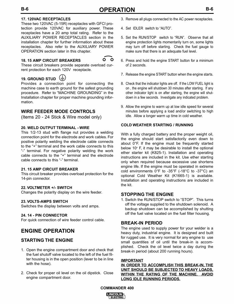
17. 120VAC RECEPTACLESThese two 120VAC (5-15R) receptacles with GFCI pro-tection provide 120VAC for auxiliary power. Thesereceptacles have a 20 amp total rating. Refer to theAUXILIARY POWER RECEPTACLES section in theinstallation chapter for further information about thesereceptacles. Also refer to the AUXILIARY POWEROPERATION section later in this chapter.
18. 15 AMP CIRCUIT BREAKERSThese circuit breakers provide separate overload cur-rent protection for each 120V receptacle.
19. GROUND STUDProvides a connection point for connecting themachine case to earth ground for the safest groundingprocedure. Refer to “MACHINE GROUNDING” in theInstallation chapter for proper machine grounding infor-mation.
20. WELD OUTPUT TERMINAL - WIREThis 1/2-13 stud with flange nut provides a weldingconnection point for the electrode and work cables. Forpositive polarity welding the electrode cable connectsto the “+” terminal and the work cable connects to this“-” terminal. For negative polarity welding the workcable connects to the “+” terminal and the electrodecable connects to this “-” terminal.
22. VOLTMETER +/- SWITCHChanges the polarity display on the wire feeder.
23. VOLTS-AMPS SWITCHSwitches the display between volts and amps.
24. 14 - PIN CONNECTORFor quick connection of wire feeder control cable.
ENGINE OPERATIONSTARTING THE ENGINE
1. Open the engine compartment door and check thatthe fuel shutoff valve located to the left of the fuel fil-ter housing is in the open position (lever to be in linewith the hose).
2. Check for proper oil level on the oil dipstick. Closeengine compartment door.
3. Remove all plugs connected to the AC power receptacles.
4. Set IDLER switch to “AUTO”.
5. Set the RUN/STOP switch to “RUN”. Observe that allengine protection lights momentarily turn on, some lightsmay turn off before starting. Check the fuel gauge tomake sure that there is an adequate fuel level.
6. Press and hold the engine START button for a minimumof 2 seconds.
7. Release the engine START button when the engine starts.
8. Check that the indicator lights are off. If the LOW FUEL light ison , the engine will shutdown 30 minutes after starting. If anyother indicator light is on after starting, the engine will shut-down in a few seconds. Investigate any indicated problem.
9. Allow the engine to warm up at low idle speed for severalminutes before applying a load and/or switching to highidle. Allow a longer warm up time in cold weather.
COLD WEATHER STARTING / RUNNING
With a fully charged battery and the proper weight oil,the engine should start satisfactorily even down toabout 0°F. If the engine must be frequently startedbelow 10o F, it may be desirable to install the optionalether starter kit (K825-1). Installation and operatinginstructions are included in the kit. Use ether startingonly when required because excessive use shortensengine life. If the engine must be operated in extremecold environments 0°F to -35°F (-18°C to -37°C) anoptional Cold Weather Kit (K1665-1) is available.Installation and operating instructions are included inthe kit.
STOPPING THE ENGINE1. Switch the RUN/STOP switch to “STOP”. This turns
off the voltage supplied to the shutdown solenoid. Abackup shutdown can be accomplished by shuttingoff the fuel valve located on the fuel filter housing.
BREAK-IN PERIODThe engine used to supply power for your welder is aheavy duty, industrial engine. It is designed and builtfor rugged use. It is very normal for any engine to usesmall quantities of oil until the break-in is accom-plished. Check the oil level twice a day during thebreak-in period (about 200 running hours).
IMPORTANTIN ORDER TO ACCOMPLISH THIS BREAK-IN, THEUNIT SHOULD BE SUBJECTED TO HEAVY LOADS,WITHIN THE RATING OF THE MACHINE. AVOIDLONG IDLE RUNNING PERIODS.
COMMANDER 400
B-7OPERATIONB-7
TYPICAL FUEL CONSUMPTION
Refer to Table B.2 for typical fuel consumption of theCommander 400’s Engine for various operating sce-narios.
Table B.2 Deutz F3L 912 Engine Fuel Consumption
WELDER OPERATION
STICK WELDING
The Commander 400 can be used with a broad rangeof DC stick electrodes.
The OUTPUT RANGE switch provides six overlappingslope controlled current ranges. The OUTPUT CON-TROL adjusts the current from minimum to maximumwithin each range. Open circuit voltage is also con-trolled by the OUTPUT CONTROL in the slope con-trolled setting. These slope controlled settings areintended for “out-of-position” welding, including pipewhere the operator would like to control the currentlevel by changing the arc length.
PIPE WELDING
When using a sloped range, high open circuit voltagesetting provides the softest arc with best resistance topop-outs. To get this characteristic, set the OUTPUTRANGE switch to the lowest setting that still providesthe current you need and set the OUTPUT CONTROLnear maximum. For example: to obtain 175 amps anda soft arc, set the OUTPUT RANGE switch to the “180MAX” position and then adjust the OUTPUT CON-TROL for 175 amps.
When a forceful “digging” arc is required, use a higher
setting and lower open circuit voltage. For example: toobtain 175 amps and a forceful arc, set the to the “230MAX” position and then adjust the OUTPUT CON-TROL to get 175 amps.
GENERAL WELDING
The seventh position of the OUTPUT RANGE switch isdesigned for horizontal welds with all types of elec-trodes especially low hydrogen. The OUTPUT CON-TROL adjusts the full range of 50 to 575 amps. Thissetting provides a soft, constant current arc. If a moreforceful arc is desired, then select the proper rangefrom the slope controlled current ranges.
TIG WELDING
The Commander 400 can be used in a wide variety ofDC Tungsten Inert Gas (TIG) welding applications forDC TIG welding up to 400A at a 20% duty cycle, 300Aat a 60% duty cycle and 250A at a 80% duty cycle.Refer to Table B.3 for recommended output settingdepending on the tungsten electrode size. TheCommander can be used without a TIG module or Hi-Freq Unit for scratch start DC TIG welding. Using aK799 Hi-Freq Unit or K930-1 TIG Module enables DCTIG welding without having to scratch start. The end ofthis section also details Commander 400 settingswhen using either of these units for DC TIG welding.Also refer to the Accessories chapter for recommend-ed equipment for TIG welding.
ARC GOUGING
Set the output range switch to the General purposeposition (50-575). For current setting, refer to TheProcedure Handbook of Arc Welding, section on arcgouging (13.5) or the consumable manufacturer’s rec-ommended current rating.
COMMANDER 400
Low Idle - NoLoad 1350 RPM
High Idle - NoLoad 1900 RPM
DC CC WeldOutput 400Amps @ 40 Volts Auxiliary Power10,000 VA
.30 gallons/hour(1.36 liters/hour)
.78 gallons/hour( 3.55 liters/hour)
1.84 gallons/hour( 8.36 liters/hour)
1.32 gallons/hour(6.00 liters/hour)
83.3
32.1
13.6
18.9
Deutz F3L 91244.2 Hp
@ 1800 RPM
Running Time for25 gallons
(Hours)
B-8OPERATIONB-8
COMMANDER 400 SETTINGS WHEN USING THEK799 HI-FREQ UNIT
a. Set the OUTPUT RANGE switch to the “50-575 set-ting” (Fabrication and General Purpose)
b. Set the IDLER switch to the “High “ position.
c. Set the LOCAL/REMOTE switch to the “Remote” posi-tion.
d. Set the WELDING TERMINALS switch to the “WeldingTerminals Always On” position. This will close the solidstate contactor and provide an always “hot” electrode.
(Note: This is necessary because the K799 circuitry withrespect to the #2 and #4 leads does not provide the prop-er signal to open and close the solid state contactor in theCommander).
COMMANDER 400 SETTINGS WHEN USING THEK930-1 TIG MODULE
a. Set the OUTPUT RANGE switch to the 50-575 Setting(Fabrication and General Purpose)
b. Set the IDLER switch to the “Auto “ position.
c. Set the LOCAL/REMOTE switch to the “Remote” posi-tion.
d. Set the WELDING TERMINALS switch to the “WeldingTerminals Remotely Controlled” position. This willkeep the solid state contactor open and provide a“cold” electrode until the triggering device (Amptrol orArc Start Switch) is pressed.
COMMANDER 400
TungstenElectrodeDiameterin. (mm)
2-155-2015-80
70-150
150-250250-400
400-500500-750750-1000
(3)(3)(3)
10-20
15-3025-40
40-5555-8080-125
3-8 (2-4)5-10 (3-5)5-10 (3-5)
5-10 (3-5)
13-17 (6-8)15-23 (7-11)
21-25 (10-12)23-27 (11-13)28-32 (13-15)
3-8 (2-4)5-10 (3-5)5-10 (3-5)
9-13 (4-6)
11-15 (5-7)11-15 (5-7)
13-17 (6-8)18-22 (8-10)23-27 (11-13)
TIG TORCHNozzle
Size (4), (5)
Approximate Argon Gas Flow Rate C.F.H. (l/min.)
DCEN (-) DCEP (+)
#4, #5, #6
#5, #6
#6, #7, #8
#8, #10
0 .010 (.25)0.020 (.50)0.040 (1.0)
1/16 (1.6)
3/32 (2.4)1/8 (3.2)
5/32 (4.0)3/16 (4.8)1/4 (6.4)
1%, 2%ThoriatedTungsten
1%, 2%ThoriatedTungsten
Aluminum Stainless Steel
Table B.3 TYPICAL CURRENT RANGES (1) FOR TUNGSTEN ELECTRODES(2)
(1) When used with argon gas. The current ranges shown must be reduced when using argon/helium or pure heliumshielding gases.
(2) Tungsten electrodes are classified as follows by the American Welding Society (AWS):Pure EWP1% Thoriated EWTh-12% Thoriated EWTh-2
Though not yet recognized by the AWS, Ceriated Tungsten is now widely accepted as a substitute for 2% ThoriatedTungsten in AC and DC applications.
(3) DCEP is not commonly used in these sizes.(4) TIG torch nozzle “sizes” are in multiples of 1/16ths of an inch:
# 4 = 1/4 in. (6 mm)# 5 = 5/16 in. (8 mm)# 6 = 3/8 in. (10 mm)# 7 = 7/16 in. (11 mm)# 8 = 1/2 in. (12.5 mm)#10 = 5/8 in. (16 mm)
(5) TIG torch nozzles are typically made from alumina ceramic. Special applications may require lava nozzles, which areless prone to breakage, but cannot withstand high temperatures and high duty cycles.
B-9OPERATIONB-9
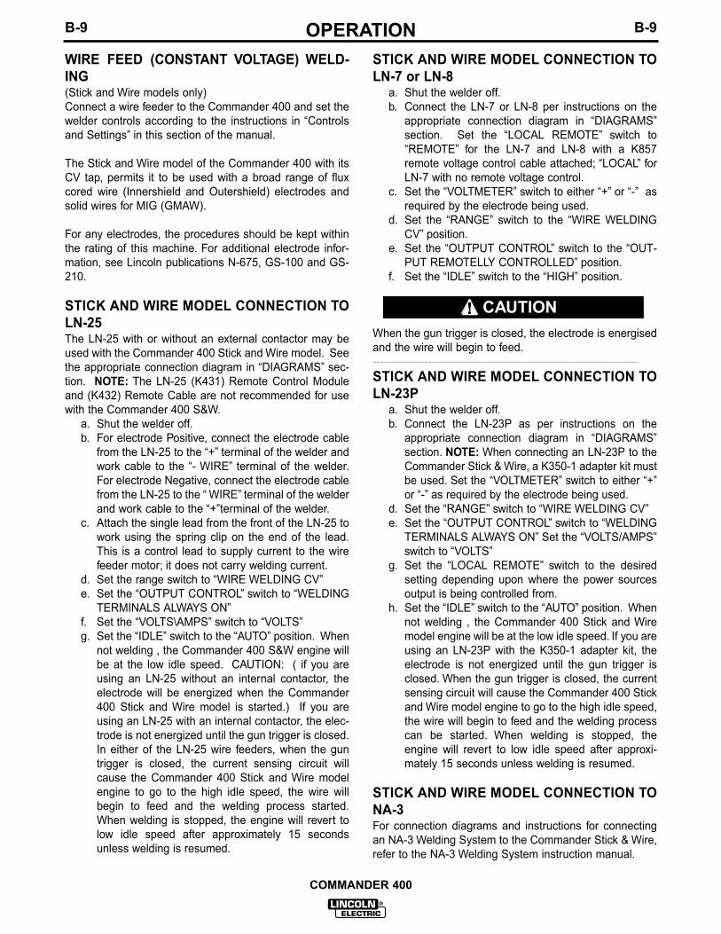
WIRE FEED (CONSTANT VOLTAGE) WELD-ING(Stick and Wire models only)Connect a wire feeder to the Commander 400 and set thewelder controls according to the instructions in “Controlsand Settings” in this section of the manual.
The Stick and Wire model of the Commander 400 with itsCV tap, permits it to be used with a broad range of fluxcored wire (Innershield and Outershield) electrodes andsolid wires for MIG (GMAW).
For any electrodes, the procedures should be kept withinthe rating of this machine. For additional electrode infor-mation, see Lincoln publications N-675, GS-100 and GS-210.
STICK AND WIRE MODEL CONNECTION TOLN-25The LN-25 with or without an external contactor may beused with the Commander 400 Stick and Wire model. Seethe appropriate connection diagram in “DIAGRAMS” sec-tion. NOTE: The LN-25 (K431) Remote Control Moduleand (K432) Remote Cable are not recommended for usewith the Commander 400 S&W.
a. Shut the welder off.b. For electrode Positive, connect the electrode cable
from the LN-25 to the “+” terminal of the welder andwork cable to the “- WIRE” terminal of the welder.For electrode Negative, connect the electrode cablefrom the LN-25 to the “ WIRE” terminal of the welderand work cable to the “+”terminal of the welder.
c. Attach the single lead from the front of the LN-25 towork using the spring clip on the end of the lead.This is a control lead to supply current to the wirefeeder motor; it does not carry welding current.
d. Set the range switch to “WIRE WELDING CV”e. Set the “OUTPUT CONTROL” switch to “WELDING
TERMINALS ALWAYS ON”f. Set the “VOLTS\AMPS” switch to “VOLTS”g. Set the “IDLE” switch to the “AUTO” position. When
not welding , the Commander 400 S&W engine willbe at the low idle speed. CAUTION: ( if you areusing an LN-25 without an internal contactor, theelectrode will be energized when the Commander400 Stick and Wire model is started.) If you areusing an LN-25 with an internal contactor, the elec-trode is not energized until the gun trigger is closed.In either of the LN-25 wire feeders, when the guntrigger is closed, the current sensing circuit willcause the Commander 400 Stick and Wire modelengine to go to the high idle speed, the wire willbegin to feed and the welding process started.When welding is stopped, the engine will revert tolow idle speed after approximately 15 secondsunless welding is resumed.
STICK AND WIRE MODEL CONNECTION TOLN-7 or LN-8
a. Shut the welder off.b. Connect the LN-7 or LN-8 per instructions on the
appropriate connection diagram in “DIAGRAMS”section. Set the “LOCAL REMOTE” switch to“REMOTE” for the LN-7 and LN-8 with a K857remote voltage control cable attached; “LOCAL” forLN-7 with no remote voltage control.
c. Set the “VOLTMETER” switch to either “+” or “-” asrequired by the electrode being used.
d. Set the “RANGE” switch to the “WIRE WELDINGCV” position.
e. Set the “OUTPUT CONTROL” switch to the “OUT-PUT REMOTELLY CONTROLLED” position.
f. Set the “IDLE” switch to the “HIGH” position.
When the gun trigger is closed, the electrode is energisedand the wire will begin to feed.------------------------------------------------------------------------STICK AND WIRE MODEL CONNECTION TOLN-23P
a. Shut the welder off.b. Connect the LN-23P as per instructions on the
appropriate connection diagram in “DIAGRAMS”section. NOTE: When connecting an LN-23P to theCommander Stick & Wire, a K350-1 adapter kit mustbe used. Set the “VOLTMETER” switch to either “+”or “-” as required by the electrode being used.
d. Set the “RANGE” switch to “WIRE WELDING CV”e. Set the “OUTPUT CONTROL” switch to “WELDING
TERMINALS ALWAYS ON” Set the “VOLTS/AMPS”switch to “VOLTS”
g. Set the “LOCAL REMOTE” switch to the desiredsetting depending upon where the power sourcesoutput is being controlled from.
h. Set the “IDLE” switch to the “AUTO” position. Whennot welding , the Commander 400 Stick and Wiremodel engine will be at the low idle speed. If you areusing an LN-23P with the K350-1 adapter kit, theelectrode is not energized until the gun trigger isclosed. When the gun trigger is closed, the currentsensing circuit will cause the Commander 400 Stickand Wire model engine to go to the high idle speed,the wire will begin to feed and the welding processcan be started. When welding is stopped, theengine will revert to low idle speed after approxi-mately 15 seconds unless welding is resumed.
STICK AND WIRE MODEL CONNECTION TONA-3For connection diagrams and instructions for connectingan NA-3 Welding System to the Commander Stick & Wire,refer to the NA-3 Welding System instruction manual.
COMMANDER 400
CAUTION
B-10OPERATIONB-10
AUXILIARY POWER OPERATION
Start the engine and set the IDLER control switch tothe desired operating mode. Full power is availableregardless of the welding control settings, if no weldingcurrent is being drawn..
The auxiliary power of the Commander consists of two-120VAC (5-15R) duplex receptacles with GFCI protec-tion and one 120/240 VAC (14-50R) receptacle. The120/240VAC receptacle can be split for single phase120 VAC operation.
The auxiliary power capacity is 10,000 watts of 60 Hz,single phase power. The auxiliary power capacity rat-ing in watts is equivalent to volt-amperes at unity powerfactor. The maximum permissible current of the 240VAC output is 44 A. The 240 VAC output can be split toprovide two separate 120 VAC outputs with a maximumpermissible current of 44 A per output to two separate120 VAC branch circuits. Output voltage is within ±10% at all loads up to rated capacity.
NOTE: The 240V receptacle has two 120V outlets ofdifferent phases and cannot be paralleled.
The auxiliary power receptacles should only be usedwith three wire grounded type plugs or approved dou-ble insulated tools with two wire plugs.
The current rating of any plug used with the systemmust be at least equal to the current capacity of theassociated receptacle.
SIMULTANEOUS WELDING AND AUXIL-IARY POWER LOADS
It must be noted that the above auxiliary power ratingsare with no welding load. Simultaneous welding andpower loads are specified in table B.4. The permissiblecurrents shown assume that current is being drawnfrom either the 120 VAC or 240 VAC supply (not both atthe same time).
* Each GFCI duplex receptacle is limited to 15 amps.** Not to exceed 44 A per 120 VAC branch circuit when splitting the 240
VAC output.
TABLE B.4 Commander 400 Simultaneous Welding and PowerLoads
C-1ACCESSORIESC-1
OPTIONAL FIELD INSTALLEDACCESSORIES
K802R POWER PLUG KIT - Provides a plug for eachreceptacle.
K857 28 ft. (8.5 m) or K857-1 100 ft. (30.4 m)REMOTE CONTROL - Portable control provides samedial range as the output control on the welder from alocation up to the specified length from the welder. Hasconvenient plug for easy connection to the welder. TheCommander 400 is equipped with a 6 pin connectorfor connecting the remote control and a toggle switchfor selecting “LOCAL” output control or “REMOTE” out-put control.
K704 ACCESSORY SET - Includes 35 feet (10 m) ofelectrode cable and 30 feet (9 m) of work cable, head-shield, work clamp and electrode holder. Cable israted at 500 amps, 60% duty cycle.
K953-1 TWO WHEEL TRAILER - For road, in-plantand yard towing. Road towing with optional fender &light kit. (For highway use, consult applicable federal,state and local laws regarding possible additionalrequirements)
K949-1 OIL DRAIN KIT - Includes ball valve, hose andclamp.
RECOMMENDED EQUIPMENT
STICK
K704 Accessory Kit which includes:• Electrode holder and cable.• Ground clamp and cable.• Headshield.
K857 Remote Control Kit is optional for remote cur-rent control.
TIG
Magnum TIG TorchMagnum Parts Kit and Argon gasK930-1 TIG Module (not required for scratch startDC TIG welding)
K936-3 Control CableK870 Foot Amptrol
Also available:
K812 Hand AmptrolK814 Arc Start SwitchK937-22 Control Cable ExtensionK937-45 Control Cable ExtensionK844-1 Water Valve
HIGH FREQUENCY GENERATORS FORTIG APPLICATIONS
The K799 Hi-Freq Unit and the K930-1 TIG Module aresuitable for use with the Commander 400. TheCommander is equipped with the required R.F. bypasscircuitry for the connection of high frequency generat-ing equipment. The high frequency bypass networksupplied with the K799 Hi-Freq Unit does NOT needto be installed into the Commander.
The Commander and any high frequency generatingequipment must be properly grounded. See the K799Hi-Freq Unit and the K930-1 TIG Module operatingmanuals for complete instructions on installation, oper-ation, and maintenance.
COMMANDER 400
D-1MAINTENANCED-1
SAFETY PRECAUTIONS
•Have a qualified technician do the maintenanceand troubleshooting work.
•Turn the engine off before working inside themachine.
•Remove guards only when necessary and replacethem when the maintenance requiring theirremoval is complete.
•Always use the greatest care when working nearmoving parts.
Read the Safety Precautions in front of this manual andthe engine instruction manual before working on thismachine.
Keep all equipment safety guards, covers and devicesin position and in good repair. Keep hands, hair, cloth-ing and tools away from V-belts, gears, fans and allother moving parts when starting, operating or repair-ing the equipment.
ROUTINE AND PERIODIC MAINTENANCE
DAILY
a. Check the crankcase oil level .
b. Refill the fuel tank to minimize moisture condensa-tion in the tank.
c. Open the water drain valve located on the bottom ofthe water separator element 1 or 2 turns and allow todrain into a container suitable for diesel fuel for 2 to3 seconds. Repeat the above drainage procedureuntil diesel fuel is detected in the container.
WEEKLY
Blow out the machine with low pressure air periodical-ly. In particularly dirty locations, this may be requiredonce a week.
ENGINE MAINTENANCE
Refer to the “Periodic Checks” section of the EngineOperator’s Manual for the recommended maintenanceschedule of the following:
a) Engine Oil and Filterb) Air Cleanerc) Fuel Filter - and Delivery Systemd) Cooling Blower Belte) Batteryf) Cooling System
Refer to Table D.1 at the end of this section for variousengine maintenance components.
AIR FILTER
EXCESSIVE AIR FILTER RESTRICTION WILLRESULT IN REDUCED ENGINE LIFE.------------------------------------------------------------------------The air filter element is a dry cartridge type. It can becleaned and reused; however, damaged elementsshould not be reused. Stop engine after 100 hours ofrunning time and clean filter element , replace the fil-ter if necessary. Service air cleaner regularly accord-ing to Engine Operator’s Manual.
1. Locate the air filter canister located behind theengine door on the top of the engine.
2. Remove air filter element.
3. Remove loose dirt from element with compressedair or water hose directed from inside out.
Compressed Air: 100 psi maximum with nozzles atleast one inch away from element.
Water Hose: 40 psi maximum without nozzle.
4. Soak element in a mild detergent solution for 15 min-utes. Do not soak more than 24 hours. Swish ele-ment around in the solution to help remove dirt.
5. Rinse elements from inside out with a gentle streamof water (less than 40 psi) to remove all suds anddirt.
6.Dry element before reuse with warm air at less than160
oF (71
oC). Do not use a light bulb to dry the ele-
ment.
COMMANDER 400
WARNING
CAUTION
D-2MAINTENANCED-2
7. Inspect for holes and tears by looking through theelement toward a bright light. Check for damaged gas-kets or dented metal parts. Do not reuse damaged ele-ments. Protect element from dust and damage duringdrying and storage.
8. Reinstall air filter element.
After six cleanings replace air filter. A cleaned filter willhave approximately 70% of the life of a new filter ele-ment. A restricted filter element may not appear exces-sively dirty.
The Commander 400 is equipped with a Fuel Pre-Filter/Water Separator Assembly located before thelift pump and a Secondary Fuel Filter located after thelift pump and before the fuel injectors. The Fuel Pre-Filter/Water Separator is mounted to the engine blockjust below the lift pump. The Secondary Fuel Filter ismounted directly to the engine just above the oil filter.
FUEL PRE-FILTER/WATER SEPARATOR ASSEM-BLY
The pre-filter is a 150 micron screen designed to pro-tect against gross fuel contamination of the water sep-arator element and the Secondary Fuel Filter. If thepre-filter becomes plugged it may be removed, inspect-ed, cleaned and reinstalled. In general this only needsto be done with each water separator element change(about every 1,000 hrs.) However if at any time exces-sive fuel contamination is suspected or a sudden fall-off in engine performance is detected the pre-filterscreen should be inspected and cleaned. Follow thefollowing procedure:
1. Close the fuel shutoff valve (Lever should be per-pendicular to the hose) located on the side of theFuel Pre-Filter/Water Separator Assembly.
2. Unscrew the cap ring located on the top of the filterheader and remove the plastic center cap and O-ring.
3. Remove the large white volume plug located direct-ly under the center cap in the upper cavity of the fil-ter header. Use a small screwdriver (or similardevice) to lift the plug part way out of the cavity toassist with its removal.
Be careful not to damage the pre-filter screen withthe tool used to remove the plug.
4. Using a pair of pliers, gently tug on the pull tabs ofthe pre-filter screen in an alternating pattern togradually remove the pre-filter screen.
5. Brush off any debris and rinse in diesel fuel.
6. Re-install the pre-filter screen into the upper cavityof the filter header making sure the four pull tabsare pointing up. Putting your fingers on the pull tabs,push down evenly until the lower body of the pre-fil-ter screen contacts the floor of the upper cavity.
7. Re-insert the large white volume plug into the uppercavity.
8. Place the O-ring onto the angled seal surface of thefilter header and re-install the plastic cap. Make sureits flange rests on the O-ring.
9. Screw on the cap ring and tighten hand tight.
10. Remember to open the fuel shutoff valve (Lever inline with the hose) before starting the engine.
WATER SEPARATOR ELEMENT
The water separator element is a two stage filter with aspecial filtration/water separating media, and anexpanded water reservoir providing maximum protec-tion against water in the fuel. The recommendedchange interval for the water separator element is1,000 hours. The procedure for changing the elementis as follows:
1. Close the fuel shutoff valve (Lever should be per-pendicular to the hose) located on the side of theFuel Pre-Filter/Water Separator Assembly.
2. Rotate the quick change ring (located just below fil-ter header) clockwise approximately 1/2 turn andslide it down and off of the element.
3. Grasp the element and pull down with a slight rock-ing motion to remove the element from the grommetpost on the bottom of the filter header.
COMMANDER 400
WARNING
D-3MAINTENANCED-3
4. Slide the new element onto the grommet post on thebottom of the filter header until the element no longereasily moves up into the filter header. Now rotate theelement (may take almost 1 full turn) with a slightupward pressure until the element begins to furtherengage the header. With the proper orientation nowestablished apply additional pressure to seat the ele-ment in the filter header. You should feel the element“pop” into place when properly seated.
Note: The element will only go on one way. Never useexcessive force when mounting the element to theheader.
5. Slide the quick change ring up over the element androtate counter clockwise until an audible click or popis heard. If you do not hear the click you have not rotat-ed the ring far enough and the element is not in thelocked position. Another indication that the ring is inthe locked position is that one set (it doesn’t matterwhich one) of arrows located on the outside of the ringshould be located directly under the air vent valve.
6. Open the fuel shutoff valve (lever in line with the hose).
7. Open the air vent valve on the front of the filter headeruntil fuel emerges free of air bubbles and then closethe air vent valve.
Note : Consult your engine operation manual for informa-tion on air -bleeding the entire fuel system.
SECONDARY FUEL FILTER
The Secondary Fuel Filter is a spin on cartridge typemount directly to the engine. Consult your engine opera-tion manual for complete information on service intervalsand element changing procedures.
COOLING SYSTEMThe cooling system of the Deutz engine needs to bechecked and cleaned periodically. Consult the engineowners manual for the proper frequency and procedure.
COOLING BLOWER BELTThe following procedure should be followed to replace thecooling blower belt:
1. Allow machine to cool.
2. Unfasten and slide the battery holder out from thewelder.
3. Disconnect the negative battery cable.
4. Remove the engine end panel for access to theengine.
5. Loosen the alternator mounting bolts and rotate thealternator towards the engine.
6. Remove the old cooling blower belt and install a newone.
7. Adjust the cold belt tension to 63-73 lbs. midwaybetween any two pulleys.
8. Reinstall the engine end panel. Reattach the negativebattery cable. Slide in and refasten the battery holder.
9. Check the cooling blower belt tension after 100 hoursof operation. (Follow steps 1,2,3,4,7 & 8)
BATTERY HANDLING
GASES FROM BATTERY can explode.• Keep sparks, flame and cigarettes away from bat-
tery.
To prevent EXPLOSION when:• INSTALLING A NEW BATTERY - disconnect nega-
tive cable from old battery first and connect to newbattery last.
• CONNECTING A BATTERY CHARGER - Remove bat-tery from welder by disconnecting negative cablefirst, then positive cable and battery clamp. Whenreinstalling, connect negative cable last. Keep wellventilated.
• USING A BOOSTER - connect positive lead to bat-tery first then connect negative lead to engine foot.
BATTERY ACID CAN BURN EYES AND SKIN.• Wear gloves and eye protection and be careful when
working near battery. Follow instructions printed onbattery.
1. When replacing, jumping, or otherwise connecting thebattery to the battery cables, the proper polarity must beobserved. Failure to observe the proper polarity couldresult in damage to the charging circuit. The positive (+)battery cable has a red terminal cover.
2. If the battery requires charging from an external charg-er, disconnect the negative battery cable first and then thepositive battery cable before attaching the charger leads.Failure to do so can result in damage to the internalcharger components. When reconnecting the cables,connect the positive cable first and the negative cablelast.
PREVENTING BATTERY DISCHARGE
If you have an ignition switch, turn it off when engine isnot running.
PREVENTING BATTERY BUCKLING
Tighten nuts on battery clamp until snug.
COMMANDER 400
WARNING
D-4MAINTENANCED-4
COMMANDER 400
Table D.1 Engine Maintenance Components
ITEM
Air Cleaner Element
Cooling Blower Belt
Oil Filter Element
Fuel Filter Element
Water Separator Element
Fuel Pre-Filter Screen
Battery
MAKE
DonaldsonAC
LincolnGates
DeutzPurolator
NapaFram
DeutzPurolator
NapaFram
LincolnStanadyne
LincolnStanadyne
PART NUMBER
P181052A302C
T13536-37585
1174418PER2168
1820PH3776
1174423PC423358
P4102
M16890-C31572
M16890-B29575
BCIGroup
34
E-1TROUBLESHOOTINGE-1
COMMANDER 400
If for any reason you do not understand the test procedures or are unable to perform the tests/repairs safely, contact your LocalLincoln Authorized Field Service Facility for technical troubleshooting assistance before you proceed.
CAUTION
This Troubleshooting Guide is provided tohelp you locate and repair possible machinemalfunctions. Simply follow the three-stepprocedure listed below.
Step 1. LOCATE PROBLEM (SYMPTOM).Look under the column labeled “PROBLEM(SYMPTOMS)”. This column describes pos-sible symptoms that the machine may exhib-it. Find the listing that best describes thesymptom that the machine is exhibiting.Symptoms are grouped into the followingcategories: engine problems, function prob-lems and output problems.
Step 2. PERFORM EXTERNAL TESTS.The second column labeled “POSSIBLEAREAS OF MISADJUSTMENT(S)” lists theobvious external possibilities that may con-tribute to the machine symptom. Performthese tests/checks in the order listed. Ingeneral, these tests can be conducted with-out removing the case wrap-around cover.
Step 3. RECOMMENDED COURSE OFACTION
If you have exhausted all of the items in step2. Contact your Local Lincoln AuthorizedField Service Facility.
HOW TO USE TROUBLESHOOTING GUIDE
Service and Repair should only be performed by Lincoln Electric Factory Trained Personnel.Unauthorized repairs performed on this equipment may result in danger to the technicianand machine operator and will invalidate your factory warranty. For your safety and to avoidElectrical Shock, please observe all safety notes and precautions detailed throughout this manual.__________________________________________________________________________
WARNING
E-2TROUBLESHOOTINGE-2
COMMANDER 400
Observe all Safety Guidelines detailed throughout this manual
If for any reason you do not understand the test procedures or are unable to perform the tests/repairs safely, contact your LocalLincoln Authorized Field Service Facility for technical troubleshooting assistance before you proceed.
CAUTION
ENGINE PROBLEMS
PROBLEMS(SYMPTOMS)
POSSIBLE AREAS OFMISADJUSTMENTS(S)
RECOMMENDEDCOURSE OF ACTION
Major Physical or Electrical Damageis Evident.
Engine will not “crank”.
Engine will “crank” but not start.
Engine shuts down shortly afterstarting.
Battery does not stay charged.
1. Contact your Local LincolnAuthorized Field Service Facility.
1. Battery is low. Charge Battery.
2. Loose battery cable connections.Inspect, clean and tighten.
1. Out of fuel. Fill prime tank.
2. Fuel shut off valve is in offposition.
3. High oil temperature (Indicatorlight lit. Check engine coolingsystem. (Consult engine servicedealer.
3. High oil temperature (Indicatorlight lit). Check engine coolingsystem. (Consult engine servicedealer.
1. Faulty battery. Replace
Contact your Local Lincoln AuthorizedField Service Facility for technicaltroubleshooting assistance.
E-3TROUBLESHOOTINGE-3
COMMANDER 400
Observe all Safety Guidelines detailed throughout this manual
If for any reason you do not understand the test procedures or are unable to perform the tests/repairs safely, contact your LocalLincoln Authorized Field Service Facility for technical troubleshooting assistance before you proceed.
CAUTION
FUNCTION PROBLEMS
PROBLEMS(SYMPTOMS)
POSSIBLE AREAS OFMISADJUSTMENTS(S)
RECOMMENDEDCOURSE OF ACTION
Engine will not idle down to lowspeed.
Engine will not go to high idle whenattempting to weld.
Engine will not go to high idle whenusing auxiliary power.
1. Idler switch in High idle position.Set switch to Auto.
2. External load on welder or auxil-iary power. Remove all externalloads.
1. Poor work lead connection towork. Make sure work clamp istightly connected to clean basemetal.
2. ”Welding Terminals” switch is inwrong position. Set to “AlwaysOn” when welding without a weld-ing terminal control cable. Referto Operations chapter for properuse of this switch.
1. Auxiliary power load is less than100 watts. Idler may not respondwith less than a 100 watt load.Set Idler to “High”
Contact your Local Lincoln AuthorizedField Service Facility for technicaltroubleshooting assistance.
E-4TROUBLESHOOTINGE-4
COMMANDER 400
Observe all Safety Guidelines detailed throughout this manual
If for any reason you do not understand the test procedures or are unable to perform the tests/repairs safely, contact your LocalLincoln Authorized Field Service Facility for technical troubleshooting assistance before you proceed.
CAUTION
OUTPUT PROBLEMS
PROBLEMS(SYMPTOMS)
POSSIBLE AREAS OFMISADJUSTMENTS(S)
RECOMMENDEDCOURSE OF ACTION
No welding power output.
Welder has output and no control.
No auxiliary power.
1. Welding terminals switch in wrongposition. Place switch in “AlwaysOn” position when welding withoutwelding terminal control cable.Refer to Operation chapter forproper switch function.
1. Local/Remote switch is in wrongposition. Place switch in Localposition to control output atwelder. Place switch in Remoteposition to control output remotely.Refer to Operation chapter forproper switch function.
2. Poor remote kit connection.Check connections.
3. Faulty remote kit. Replace if nec-cessary.
1. Open circuit breakers. Resetbreakers. If breakers keep trip-ping check connections to auxil-iary receptacles. Also make sureload does not exceed receptaclescurrent rating. Refer to AuxiliaryConnections in the Installationand Operation chapters.
2. Faulty connections to auxiliaryreceptacles. Check connections.
3. GFCI tripped. Clear any groundfault and reset GFCI circuit bypressing “Reset” button on the120 V receptacle.
Contact your Local Lincoln AuthorizedField Service Facility for technicaltroubleshooting assistance.
F-1DIAGRAMSF-1
COMMANDER 400
NO
TE:T
his
diag
ram
is fo
r ref
eren
ce o
nly.
It m
ay n
ot b
e ac
cura
te fo
r all
mac
hine
s co
vere
d by
this
man
ual.
The
spec
ific
dia-
gram
for y
our p
artic
ular
mac
hine
is p
aste
d in
side
the
mac
hine
on
one
of th
e en
clos
ure
pane
ls.
WIRING DIAGRAM:
240 uF
240 uF
240 uF
STATOR
ASSEMBLY
RECTIFIER
SHUNT
600 AMP
CHOKE
OUTPUT
SCR A
SCR B
SCR C
G1
G2
G3
G1
G2
G3
12
36
82
31
23
204S
206S
204S
206S
207
SNUBBER PC BOARD
12
3
221
220
219
218
217
216
215
214
213
222
1 2 3 4 5 6 7 8 9 10
213
214
215
216
217
218
219
220
221
222
261
223
204
50 Ohm
100 W
120 V
WHITE
120/240V
15A
CB4 15A
CB3
CB1
CB2
11
12
9
6A
50A
50A
9
11
12
TERM.
3A
GREENGREENGREEN
WHITE
BLACK
BLACK
BLACK
8
8
GND-C
GND-D
E1
E2
3
IDLER
SWITCH
AUTO
S4
SWITCH
FINE CONTROL
POT
SELECTOR
S1
42
76
75
75
77
77
76B
77B
76
12 VOLT
BATTERY
(+)
(-)
COIL
COIL
PULL
HOLD SOLENOID
IDLE
ENGINE GROUND
1J2
13
4
B1
E2
E1
MOTOR
+
-
232
231A
231A
236C
240
234
233A
255
GROUND SCREW
3
GND-E
5C
5A
5
5C
5C
236B
236A
METER
HOUR
SENSOR
SENSOR FUEL LVL.
S2
232A
239A
229241
J10
6
WHITE
5E 5G
5G
5E
5H
5H
5C
GROUND SCREW
IN CONTROL BOX
GND-D
GND-C
GND-E
IN CONTROL BOX
6B
3B
S3
START BUTTON
HIGH
3
BLACK
6 BLACK
IN CONTROL BOX
T1
1002
1004
1006
1008
1011
1013
1015
1009
1010
1012
1014
1016
1017
1019
1021
1023
1018
1020
1022
1024
1001
1003
1005
1007
1002
1004
1006
1008
CAPACITOR
T2
T3
S8
W5
CONNECTOR CAVITY NUMBERING SEQUENCE
(VIEWED FROM COMPONENT SIDE OF BOARD)
ELECTRICAL SYMBOLS PER E1537
NEG.
POS.
RUN
STOP
242E
239A
229B
245
243
56
78
242D
247
227
239
EXC
NEG
POS
SENSE
226
225
224
STARTER
SOLENOID
ALTERNATOR
242
242
NEXT AVLB.
S6
A CB D E F
AMPHENOL 2
77D
76D
75D 2D
4D
REMOTE
CONTROL
GROUND
TRIGGER
77C
GFCI
LINE
LOAD
LOAD
LINE
HOT
WHITE
WHITE
HOT
227
75B
J12
METER
PCB
12
34
1 2 3 4
250
251
252
253
9
87
65
4
3 2
1
A
226
234
246
242G
12
34
56
SENSOR
SWITCH
SWITCH
228A
241A
229A
239
239B
1 2 3 4 5 6 7 8
ENGINE TO PCB HARNESS
PANEL TO PANEL WIRES
PANEL TO PCB HARNESS
120 V
GFCI
LINE
LOAD
LOAD
LINE
HOT
WHITE
WHITE
HOT
J11
239B
242I
204B
209
9
237
J16
P16
254
COIL
COIL
PULL
HOLD SOLENOID
SHUTDOWN
256
232
224
242D
76C
228
STARTING
206 6 8 15
16
SPI
SCI
OUTPUT
SOURCE
CONTROL
ALWAYS ON
OUTPUT REMOTELY
CONTROLLED
CW
VIEWED FROM
BACK
11
12 13
14
23
56
89
4
267
238
262
262
261
204
223
CC
BYPASS PC
BOARD
260
12
34
56
78
910
270
269
268
272
273
270
269
268
272
273
REMOTE/
LOCAL
SWITCH
GND-F
GND-F
87
65
204A
2 4
WELDED STUD
ON OUTPUT PANEL
GND-A
DC
DB
DA
DD
AUX. POWER
B3
B2
4
J30
260
ENGINE PROT.
BOARD
J23
J8
J4
J1
J6
J7
J3 237
274
280
10
207
233
280
279
10
11
256
255
STAINLESS STEEL
STAND-OFF
FRAME GROUND
14
712
14
47
9
204A
T3
T2
T1
6
55A
3
EXCITER
WINDINGS
W1
W5
W2
W6
W3
W3
W6
W1
W4
W2
240
287
SOLENOID GROUND
STUD ON ENGINE
4
279
236A
233A
233
240
240A
MOTHER
CONTROL
PC BOARD
J5
J40
J50
STUD ON ENGINE
MOUNT CHANNEL STUD
ON
ENGINE
CONNECTIONS TO
CAPACITORS MADE
EXCITER
VOLTAGE
FEEDBACK BOARD
5D
3D
3D
3D
5D
3D
5D
3D
NEUTRAL T2 STUD
T1 INSULATED STUD
T3
INSULATED STUD
(optional)
232H
CONNECTIONS
WK
G
OIL TEMP. SENSOR & SWITCH
+
-
AMMETER
229A
+ -
+ -
+ -
FUEL
SS
S
228A
241A
232B
TEMP.
232C
232A
242B
242A
242C
LOW
FUEL
LOW
PRESS.
245
OIL
PRESS.
TEMP.
ALT.
243
236C
229B
247
246
238
242G
232E
232G
232F
232D
L11008
COMMANDER 400-STICK MODEL WIRING DIAGRAM
1 2 3 4 5
J60
2
4D
75D
76D
2D
77D
3 4 5 61 7 86
77C
75B
76C
4B
2B
4B
2B
FRAME GROUND
J61
(VIEWED FROM BACK)
REMOTE PROTECTION PCB
AUXILIARY BYPASS PCB
5J
9A
5K
8A
5J
9A
5K
8A
AUX. CURRENT
SENSE TOROID
8A
5J
9A
5K
8A
5J
9A
5K
B4
B5
B6
B7
9A
5K
5J
8A
5D
274
240A
CONTROL HARNESS
CONTROL HARNESS
CONTROL HARNESS
ENGINE HARNESS TO PANEL WIRES
ENGINE HARNESS
CONTROL PANEL
GND-H
ON CONTROL PANEL
SMALL
TABLARGE
TAB
SILVER
TAB
SILVER
TAB
SILVER
TAB
STUD ON GENERATOR
MOUNT CHANNEL
STAINLESS STEEL
STAND-OFF
FRAME GROUND
STAINLESS STEEL
STAND-OFF
FRAME GROUND
W4
W6
242I
CONNECTIONS ON CONTROL BOARD
(VIEWED AS INSTALLED)
J2
J6
J5
J8
J7
J1
J4
J3
B1
B2
B3
J23
ENGINE
PROT.
BOARD
POSITION NAMEPLATE SETTING
SELECTOR SWITCH (S8)
1 NO FUNCTION
2 NO FUNCTION
3 90 MAX
4 120 MAX
5 180 MAX
6 230 MAX
7 270 MAX
8 400 MAX
9 50-575
(SEE SELECT SWITCH CHART)
STAINLESS STEEL
STAND-OFF
COMMON BATT.
285
285
OIL PRESSURE SWITCH
& SENSOR286
BOLT ONTO
SENDER BRK’T
VIA BOLTED
5-15-98A
F-2DIAGRAMSF-2
COMMANDER 400
NO
TE:T
his
diag
ram
is fo
r ref
eren
ce o
nly.
It m
ay n
ot b
e ac
cura
te fo
r all
mac
hine
s co
vere
d by
this
man
ual.
The
spec
ific
dia-
gram
for y
our p
artic
ular
mac
hine
is p
aste
d in
side
the
mac
hine
on
one
of th
e en
clos
ure
pane
ls.
WIRING DIAGRAM:COMMANDER 400-STICK & WIRE MODEL WIRING DIAGRAM
6
2
30 M
AX.
9
5
0-57
5
8
4
00 M
AX.
7
2
70 M
AX.
2
W
IRE
WELD
ING
CV
5
1
80 M
AX.
4
1
20 M
AX.
3
9
0 MA
X.
1
N
O FU
NCTI
ON
POSI
TION
NA
MEPL
ATE
SETT
ING
FROM BACK)
(VIEWED
S8
216
5FINE CONTROL
2
46
215
208A
POT
3219
214
A
NEG.
220
CW
CC
77
77B
CV28
4B
222
BOARD
284
1
CHOK
E28
4A
L2
CV
3
216
217
218
4
219
4
220
5
221
222
5
6 7
E2
E1
237
9
6
226
227
234
21
34
59
87
65
43
21
12
6
77D
2
4B 2D
6
2B 76D
76C
J62
208282
32
21
1
206S
208A
S5
SWITCH
POLARITY
ELECTRODE
4
285A
285
SHUNT
4D
31 32A
21
77E
76E
H E F
242H
WORK
G I K B
242I
F
AMPHENOL 1
GROUND
223
204
EXCITER VOLTAGE
FEEDBACK BOARD
ENGINE
J50
OIL PRESSURE SWITCH & SENSOR
OIL TEMP. SENSOR & SWITCH
STUD ON ENGINE
MOUNT CHANNEL
MOUNT CHANNEL STUD ON
STUD ON GENERATOR
11
12
STAINLESS STEEL
T3
1005
1024
1003
T2
1023
1016
1021
T1
10155D
1008
3D
1002
1013
1014
240 uF
1012
1010
1017
1019
1006
1011
240 uF
1004
1009
3D
WHITE
5H
TERM.
WHITE
GND-C
GREEN
GFCI
J11
HOT
LOAD
HOT
115 V
LINE
9
GREEN
WELDED STUD
WHITE
5G
LOAD
WHITE
9
12
B6
11
B5B4
FRAME
GROUND
STAND-OFF
B7
10
207
98
43
21
21
204S
76 J6
253
252
251
250
J1 COMMON BATT.
206
SELECTOR SWITCH (S8)
LINE
GFCI
GND-A
8
LOAD
WHITE
BLACK
3D
15A
3A
CB3
WHITE
AMMETER
6B
T1 INSULATED STUD
50A
IN CONTROL BOX
+
50A
CB2
CB1
238
6A
BLACK
J12
3D
115 V
5G
LINE
HOT
LOAD
HOT
11
10
J6
J5
262
J2
POS
J8
SENSE
1
MOTHER
CONTROL
2
PC BOARD
213
3
214
239
215
234
SENDER
BRACKET 286
BOLT ON
10
3D
9
240A
87
273
6
272
55D
3
T3
T2
EXCITER
WINDINGS
6
4
36
5A
5 ON OUTPUT PANEL
GND-E
GND-D
GND-C
IN CONTROL BOX
GROUND SCREW
AUX. POWER
5C
E1
274
268
STATOR
2
269
CONNECTIONS
CAPACITORS MADE
1
CONNECTIONS TO
270
VIA BOLTED
247
LOW
PRESS.
J40
5
77D
1
76D
4D
2
2D
76E
34 5
75D
3
SWITCH
SENSOR
FUEL LVL.
ENGINE TO PANEL HARNESS
SENSOR
228 241
242E
229
239
P16
J16
8 9
228A
241A
242D
229A
239B
233A
WK
SWITCH
285
PANEL TO PANEL WIRES
54 6 73
G
2
SENSOR
1
(-)
232C
245
229B
232B
246
232A
FUEL
232F
LOW
+
FUEL
S
TEMP.
OIL
-
TEMP.
243
+
232E
S
PRESS.
229A
-
242
5K
CONTROL
8A
REMOTE
BCONTROL
C75D
D
AUXI
LIAR
Y BY
PASS
PCB
J
9A5K
5J8A
A
GROUND
242I 242H
AMPHENOL 2
75E
7
CB5
15AM
P
REMOTE
2E
4E
CD
CONTACTOR
115AC
RF BYPASS
PC BOARD
1
W2
W5
75E
242H
242I
77E
32A
A
CONTACTOR
E
1 3
J60
CONT
ROLL
ED
4
J21
4
ALWA
YS O
N
OUTP
UT R
EMOT
ELY
FRAM
E GR
OUND
5J9A
8
75B
4
77C
277
J61
7
267
8 9 10 11
14 1 4
1
J2
232
3
J3 4
56
233
233A
232H
S3
RUN
STOP
232A
236A
285
6
CONNECTOR CAVITY NUMBERING SEQUENCE
(VIEWED FROM COMPONENT SIDE OF BOARD)
NEXT AVAILABLE 287
76
1 2 3 4 5
8
G4
10
283
21
CV D
AUGH
TER
BOAR
D
77
3 2
J20
1 2
6 5
4E
2E
ELECTRICAL SYMBOLS PER E1537
255
S4
AUTO
HIGH
PULL
SOLENOID GROUND
-
+
239B
METER
HOUR
PANEL TO PCB HARNESS
COIL
PULL
227
COIL
262
SOLENOID
IDLE
225
COIL
HOLD
SOLENOID
226
240
COIL
ENGINE TO PCB HARNESS
HOLD
224
SHUTDOWN 239A
242G
STUD ON ENGINE
237
236A
IDLER
SWITCH
256
S2
254
231A
236C
206A
SCR
C
204B
204C
268
270
273
280
G2
POS.
207
204S
277
G4
280
206
NOTE:
NO CONNECTION
C1-C
4
SWITCH
SEE CHART
206A
213
POS.
283
DE
FRAME
GROUND
NEG.
BYPASS PC
ON NEWER MODELS
E2
1022
1020
1007
1018
1008
5H
5D
1001
1006
1004
1002
240 uF
55A
GREEN
GND-E
GND-D
5D 5E
3
W6
3
W3 2
W4
W1
6
W3
W5
W4
W6
W1
6
2B
OUTPUT 4B
S6
CONTROL
SOURCE
63
63
6
32
GND-F
W2
240
245
232
239A
236B
224
BOARD
247
5
START BUTTON
2
240
13
ENGINE PROT.
233
6
12
229B
J7
43
1
B3
B2
B1
2468
2437
J23
J21
J4ENGINE
PROT.
BOARD
B2
B1
J1
J23 J3
J8
J7
CONNECTIONS ON CONTROL BOARD
(VIEWED AS INSTALLED)
CV
BOARD
B3
6
3
208
3
279
6
OUTP
UT
CHOK
EL1
221
BACK
76B
75
VIEWED FROM
7
9
75
217
8
218
76C
231A
STARTER
+
242G
S
232D
-
241A
242A
ALT.
232G
ENGINE TO PANEL HARNESS
-
228A
242C
242B
242D
236C
5C
INSTRUMENT PANEL
GROUND SCREW
IN CONTROL BOX
ALTERNATOR
238
MOTOR E
XC
NEG
STARTING
SOLENOID
PCB
3 2 1 5 6 7
SPI
8
J5
SCI
STAND-OFF
240A
STAINLESS STEEL
FRAME GROUND
METER
SELECTOR
261
260
261
204
223
300W
R3-12
R2-12
282
21
DB
SCR
1
ASSE
MBLY
600 AMP
CURRENT
SENSE TOROID
SCR
B
30,0
00 u
FDD
R1-50
100 W 209
DC
209A
77C
REMOTE/
LOCAL
SWITCH
S1
S9
260
V A
VOLT
/AMP
J30
4
275B
SWIT
CH
76
256
255
269
206S
G1
G3
204A
G2
G1
G3
204A RE
CTIF
IER
SCR
A
DA
BLACK
3IN CONTROL BOX
INSULATED STUD
T3
3B
15A
CB4
5C
BLACK
J10
115/230V
5H
BLACK
8
5E
WHITE
LINE
31
T1
IN CONTROL BOX
NEUTRAL T2 STUD
5-15-98A
L11009
7
272
274
68
279
12
34
4
43
5C
12 VOLT
(+)
GND-F
GND-H
ENGINE GROUND
J4
BATTERY
242
F-3DIAGRAMSF-3
COMMANDER 400
CONNECTION DIAGRAM:
CONTROL MODULE. INCORRECT SWITCH POSITION COULD RESULT IN DAMAGE TO THE CONTROL MODULE AND/OR POWER SOURCE.
K487-25
SPOOL GUN
BE SURE THAT CONTROL MODULE MODE SLIDE SWITCH IS IN THE "LINCOLN" (CONTACT CLOSURE) POSITION BEFORE ATTEMPTING TO OPERATE
N.B. USE VOLTMETER SWITCH TO SELECT DESIRED ELECTRODE POLARITY. POSITION THE RANGE SWITCH TO "WIRE WELDING CV".
K691-10
INPUT CABLE
K488 SG
DAMAGED. THE ENGINE GOVERNOR SETTING IS PRE-SET AT THE FACTORY - DO NOT ADJUST ABOVE RPM SPECIFICATIONS LISTED IN
Keep guards in place.
or service this equipment.
TO WORK
RECEPTACLE
CAUTION :
AN INCREASE IN THE THE AC AUXILIARY VOLTAGE. IF THIS VOLTAGE GOES OVER 140 VOLTS, WIRE FEEDER CONTROL CIRCUITS MAY BE
CONTROL MODULE
Keep away from moving parts.
ANY INCREASE OF THE HIGH IDLE ENGINE RPM BY CHANGING THE GOVERNOR SETTING OR OVERRIDING THE THROTTLE LINKAGE WILL CAUSE
Only qualified personnel should install,use
Do not touch electrically live parts.
before servicing.
Disconnect NEGATIVE (-) BATTERY LEAD
Do not operate with panels open.
N.A. WELDING CABLE MUST BE OF PROPER CAPACITY FOR THE CURRENT AND DUTY CYCLE OF IMMEDIATE AND FUTURE
N.B. USE VOLTMETER SWITCH TO SELECT DESIRED ELECTRODE POLARITY. POSITION THE RANGE SWITCH TO "WIRE WELDING CV".
ELECTRODE CABLE
TO WIRE FEED UNIT
N.A. WELDING CABLES MUST BE OF PROPER CAPACITY FOR THE CURRENT AND DUTY CYCLE OF IMMEDIATE AND FUTURE
AN INCREASE IN THE THE AC AUXILIARY VOLTAGE. IF THIS VOLTAGE GOES OVER 140 VOLTS, WIRE FEEDER CONTROL CIRCUITS MAY BE
ANY INCREASE OF THE HIGH IDLE ENGINE RPM BY CHANGING THE GOVERNOR SETTING OR OVERRIDING THE THROTTLE LINKAGE WILL CAUSE
DAMAGED. THE ENGINE GOVERNOR SETTING IS PRE-SET AT THE FACTORY - DO NOT ADJUST ABOVE RPM SPECIFICATIONS LISTED IN
12-13-96
F-11DIAGRAMSF-11
COMMANDER 400
DIMENSION PRINT
FOR BATTERY
REMOVAL.
19.63
23.69
28.99
50.38
54.44
1.26
6-21-96
45.67
CENTER OF GRAVITY
WITH OIL IN ENGINE
AND FULL FUEL TANK.
6.56
*63.10
*6.55
15.75
14.63
*
42.00
37.30
45.38
*6.5324.97
BOTTOM VIEW OF
WELDER BASE.
48.64
10.22
29.50
29.50
32.06
48.30
*TRAILER MOUNTING HOLE LOCATIONS.
31.50
M17685
F-12NOTESF-12
COMMANDER 400
Now Available...12th EditionThe Procedure Handbook of Arc Welding
With over 500,000 copies of previous editions publishedsince 1933, the Procedure Handbook is considered by many to be the “Bible” of the arc welding industry.
This printing will go fast so don’t delay. Place your order now using the coupon below.
The hardbound book contains over 750 pages of welding infor-mation, techniques and procedures. Much of this material has never been included in any other book.
A must for all welders, supervisors, engineers anddesigners. Many welding instructors will want to use the book asa reference for all students by taking advantage of the low quan-tity discount prices which include shipping by4th class parcel post.
$15.00 postage paid U.S.A. Mainland
How To Read Shop Drawings
The book contains the latest information and applicationdata on the American Welding Society Standard WeldingSymbols. Detailed discussion tells how engineers and drafts-men use the “short-cut” language of symbols to pass onassembly and welding information to shop personnel.
Practical exercises and examples develop the reader’s abilityto visualize mechanically drawn objects as they will appear intheir assembled form.
187 pages with more than 100 illustrations. Size 8-1/2” x 11”Durable, cloth-covered board binding.
$4.50 postage paid U.S.A. Mainland
New Lessons in Arc WeldingLessons, simply written, cover manipulatory techniques;
machine and electrode characteristics; related subjects, suchas distortion; and supplemental information on arc weldingapplications, speeds and costs. Practice materials, exercises,questions and answers are suggested for each lesson.
528 pages, well illustrated, 6” x 9” size, bound in simulated,gold embossed leather.
$5.00 postage paid U.S.A. Mainland
Need Welding Training?The Lincoln Electric Company operates the oldest and
most respected Arc Welding School in the United States at itscorporate headquarters in Cleveland, Ohio. Over 100,000 studentshave graduated. Tuition is low and the training is “hands on”
For details write: Lincoln Welding School22801 St. Clair Ave.Cleveland, Ohio 44117-1199.
and ask for bulletin ED-80 or call 216-383-2259 and ask for theWelding School Registrar.
Lincoln Welding SchoolBASIC COURSE $700.00
5 weeks of fundamentalsThere is a 10% discount on all orders of $50.00 or more for shipment at one time to one location.Orders of $50 or less before discount or orders outside of North America must be prepaid with charge, check or money order in U.S. Funds Only.Prices include shipment by 4 th Class Book Rate for U.S.A. Mainland Only. Please allow up to 4 weeks for delivery.UPS Shipping for North America Only. All prepaid orders that request UPS shipment please add:
$5.00 For order value up to $49.99$10.00 For order value between $50.00 & $99.99$15.00 For order value between $100.00 & $149.00
For North America invoiced orders over $50.00 & credit card orders, if UPS is requested, it will be invoiced or charged to you at cost.Outside U.S.A. Mainland order must be prepaid in U.S. Funds. Please add $2.00 per book for surface mail or $15.00 per book for air parcel post shipment.METHOD OF PAYMENT: (Sorry, No C.O.D. Orders)
Signature as it appears on Charge Card:Account No. |_|_|_|_|_|_|_|_|_|_|_|_|_|_|_|_|_|_|_|_|_| Exp Date |_|_| |_|_| ______________________Month Year
USE THIS FORM TO ORDER: Order from: BOOK DIVISION, The Lincoln Electric Company, 22801 St. Clair Avenue, Cleveland, Ohio 44117-1199BOOKS OR FREE INFORMATIVE CATALOGS Telephone: 216-383-2211 or, for fastest service, FAX this completed form to: 216-361-5901.
Lincoln Welding School Titles: Price Code Quantity Cost(ED-80) New Lessons in Arc Welding $5.00 L
Seminar Information Procedure Handbook “Twelfth Edition” $15.00 PH(ED-45) How to Read Shop Drawings $4.50 H
Educational Video Information Incentive Management $5.00 IM(ED-93) A New Approach to Industrial Economics $5.00 NA
James F. Lincoln Arc Welding The American Century of John C. Lincoln $5.00 ACFoundation Book Information Welding Preheat Calculator $3.00 WC-8
(JFLF-515) Pipe Welding Charts $4.50 ED-89SUB TOTAL
Additional Shipping Costs if anyTOTAL COST
VISA ®MasterCardMasterCard
®
WARNING
AVISO DEPRECAUCION
ATTENTION
WARNUNG
ATENÇÃO
Spanish
French
German
Portuguese
Japanese
Chinese
Korean
Arabic
READ AND UNDERSTAND THE MANUFACTURER’S INSTRUCTION FOR THIS EQUIPMENT AND THE CONSUMABLES TOBE USED AND FOLLOW YOUR EMPLOYER’S SAFETY PRACTICES.
SE RECOMIENDA LEER Y ENTENDER LAS INSTRUCCIONES DEL FABRICANTE PARA EL USO DE ESTE EQUIPO Y LOSCONSUMIBLES QUE VA A UTILIZAR, SIGA LAS MEDIDAS DE SEGURIDAD DE SU SUPERVISOR.
LISEZ ET COMPRENEZ LES INSTRUCTIONS DU FABRICANT EN CE QUI REGARDE CET EQUIPMENT ET LES PRODUITS AETRE EMPLOYES ET SUIVEZ LES PROCEDURES DE SECURITE DE VOTRE EMPLOYEUR.
LESEN SIE UND BEFOLGEN SIE DIE BETRIEBSANLEITUNG DER ANLAGE UND DEN ELEKTRODENEINSATZ DES HER-STELLERS. DIE UNFALLVERHÜTUNGSVORSCHRIFTEN DES ARBEITGEBERS SIND EBENFALLS ZU BEACHTEN.
● Do not touch electrically live parts orelectrode with skin or wet clothing.
● Insulate yourself from work andground.
● No toque las partes o los electrodosbajo carga con la piel o ropa moja-da.
● Aislese del trabajo y de la tierra.
● Ne laissez ni la peau ni des vête-ments mouillés entrer en contactavec des pièces sous tension.
● Isolez-vous du travail et de la terre.
● Berühren Sie keine stromführendenTeile oder Elektroden mit IhremKörper oder feuchter Kleidung!
● Isolieren Sie sich von denElektroden und dem Erdboden!
● Não toque partes elétricas e elec-trodos com a pele ou roupa molha-da.
● Isole-se da peça e terra.
● Keep flammable materials away.
● Mantenga el material combustiblefuera del área de trabajo.
● Gardez à l’écart de tout matérielinflammable.
● Entfernen Sie brennbarres Material!
● Mantenha inflamáveis bem guarda-dos.
● Wear eye, ear and body protection.
● Protéjase los ojos, los oídos y elcuerpo.
● Protégez vos yeux, vos oreilles etvotre corps.
● Tragen Sie Augen-, Ohren- und Kör-perschutz!
● Use proteção para a vista, ouvido ecorpo.
WARNING
AVISO DEPRECAUCION
ATTENTION
WARNUNG
ATENÇÃO
Spanish
French
German
Portuguese
Japanese
Chinese
Korean
Arabic
LEIA E COMPREENDA AS INSTRUÇÕES DO FABRICANTE PARA ESTE EQUIPAMENTO E AS PARTES DE USO, E SIGA ASPRÁTICAS DE SEGURANÇA DO EMPREGADOR.
● Keep your head out of fumes.● Use ventilation or exhaust to
remove fumes from breathing zone.
● Los humos fuera de la zona de res-piración.
● Mantenga la cabeza fuera de loshumos. Utilice ventilación oaspiración para gases.
● Gardez la tête à l’écart des fumées.● Utilisez un ventilateur ou un aspira-
teur pour ôter les fumées des zonesde travail.
● Vermeiden Sie das Einatmen vonSchweibrauch!
● Sorgen Sie für gute Be- undEntlüftung des Arbeitsplatzes!
● Mantenha seu rosto da fumaça.● Use ventilação e exhaustão para
remover fumo da zona respiratória.
● Turn power off before servicing.
● Desconectar el cable de ali-mentación de poder de la máquinaantes de iniciar cualquier servicio.
● Débranchez le courant avant l’entre-tien.
● Strom vor Wartungsarbeitenabschalten! (Netzstrom völlig öff-nen; Maschine anhalten!)
● Não opere com as tampas removidas.● Desligue a corrente antes de fazer
serviço.● Não toque as partes elétricas nuas.
● Do not operate with panel open orguards off.
● No operar con panel abierto oguardas quitadas.
● N’opérez pas avec les panneauxouverts ou avec les dispositifs deprotection enlevés.
● Anlage nie ohne Schutzgehäuseoder Innenschutzverkleidung inBetrieb setzen!
● Mantenha-se afastado das partesmoventes.
● Não opere com os paineis abertosou guardas removidas.
• Sales and Service through Subsidiaries and Distributors Worldwide •Cleveland, Ohio 44117-1199 U.S.A. TEL: 216.481.8100 FAX: 216.486.1751 WEB SITE: www.lincolnelectric.com
World's Leader in Welding and Cutting Products Premier Manufacturer of Industrial Motors
STATEMENT OF LIMITED WARRANTYThe Lincoln Electric Company (Lincoln) warrants to the enduser (purchaser) of all new welding and cutting equipment,electrode and flux (collectively called the “Goods”) that it willbe free of defects in workmanship and material.
This warranty is void if Lincoln or its Authorized ServiceFacility finds that the equipment has been subjected toimproper installation, improper care or abnormal opera-tions.
WARRANTY PERIOD (1) (2) (3)
Lincoln will assume both the parts and labor expense ofcorrecting defects during the full warranty period. All war-ranty periods date from the date of purchase to the originalend user and are as follows:
7 Years• Main power rectifiers on all non-inverter low frequency (50
and 60 Hz) type welders.
3 Years• All Lincoln welding machines, wirefeeders and plasma
Invertec V100-S, Invertec V130-S, Invertec V200-T Power Arc 4000Pro-Cut 20
• All water coolers (internal or external models)
• All stick electrode, welding wire and flux.
• Arc welding and cutting robots and robotic controllers
• All Environmental Systems equipment, including portableunits, central units, gun and cable assemblies and acces-sories. (Does not include consumable items listed under30 day warranty.)
• All welding and cutting accessories including gun andcable assemblies, TIG and plasma torches, spool guns,wire feed modules, undercarriages, field installed optionsthat are sold separately, unattached options, welding sup-plies, standard accessory sets, replacement parts, andMagnum products. (Does not include expendable partslisted under 30 day warranty)
30 Days• All consumable items that may be used with the environ-
mental systems described above. This includes hoses, fil-ters, belts and hose adapters.
• Expendable Parts - Lincoln is not responsible for thereplacement of any expendable part that is required dueto normal wear.
CONDITIONS OF WARRANTYTO OBTAIN WARRANTY COVERAGE:The purchaser must contact Lincoln or Lincoln’s AuthorizedService Facility about any defect claimed under Lincoln’swarranty.
Determination of warranty on welding and cutting equipmentwill be made by Lincoln or Lincoln’s Authorized ServiceFacility.
WARRANTY REPAIR:If Lincoln or Lincoln’s Authorized Service Facility confirmsthe existence of a defect covered by this warranty, the defectwill be corrected by repair or replacement at Lincoln’soption.
At Lincoln’s request, the purchaser must return, to Lincoln orits Authorized Service Facility, any “Goods” claimed defec-tive under Lincoln’s warranty.
FREIGHT COSTS:The purchaser is responsible for shipment to and from theLincoln Authorized Service Facility.
WARRANTY LIMITATIONSLincoln will not accept responsibility or liability for repairsmade outside of a Lincoln Authorized Service Facility.
Lincoln’s liability under this warranty shall not exceed thecost of correcting the defect of the Lincoln product.
Lincoln will not be liable for incidental or consequential dam-ages (such as loss of business, etc.) caused by the defector the time involved to correct the defect.
This written warranty is the only express warranty providedby Lincoln with respect to its products. Warranties impliedby law such as the warranty of merchantability are limited tothe duration of this limited warranty for the equipmentinvolved.
This warranty gives the purchaser specific legal rights. Thepurchaser may also have other rights which vary from stateto state.
(1) Equipment manufactured for the Lincoln Electric Company is subject to thewarranty period of the original manufacturer.
(2) All engines and engine accessories are warranted by the engine or engineaccessory manufacturer and are not covered by this warranty.
(3) SAE400 WELD N’ AIR compressor is warranted by the compressor manu-facturer and not covered by this warranty.