Safety Depends on YouLincoln arc welding and cuttingequipment is designed and builtwith safety in mind. However, youroverall safety can be increased byproper installation ... and thought-ful operation on your part. DONOT INSTALL, OPERATE ORREPAIR THIS EQUIPMENTWITHOUT READING THISMANUAL AND THE SAFETYPRECAUTIONS CONTAINEDTHROUGHOUT. And, mostimportantly, think before you actand be careful.
For use with machine Code Numbers 10564For use with machine Code Numbers
• Sales and Service through Subsidiaries and Distributors Worldwide •
This manual covers equipment which is no longer in production by The Lincoln Electric Co. Speci�cations and availability of optional features may have changed.
FOR ENGINEpowered equipment.
1.a. Turn the engine off before troubleshooting and maintenancework unless the maintenance work requires it to be running.
____________________________________________________1.b. Operate engines in open, well-ventilated
areas or vent the engine exhaust fumes outdoors.
____________________________________________________1.c. Do not add the fuel near an open flame
welding arc or when the engine is running.Stop the engine and allow it to cool beforerefueling to prevent spilled fuel from vaporiz-ing on contact with hot engine parts andigniting. Do not spill fuel when filling tank. Iffuel is spilled, wipe it up and do not startengine until fumes have been eliminated.
____________________________________________________1.d. Keep all equipment safety guards, covers and devices in
position and in good repair.Keep hands, hair, clothing andtools away from V-belts, gears, fans and all other movingparts when starting, operating or repairing equipment.
1.e. In some cases it may be necessary to remove safetyguards to perform required maintenance. Removeguards only when necessary and replace them when themaintenance requiring their removal is complete.Always use the greatest care when working near movingparts.
___________________________________________________1.f. Do not put your hands near the engine fan.
Do not attempt to override the governor oridler by pushing on the throttle control rodswhile the engine is running.
___________________________________________________1.g. To prevent accidentally starting gasoline engines while
turning the engine or welding generator during maintenancework, disconnect the spark plug wires, distributor cap ormagneto wire as appropriate.
iSAFETYi
ARC WELDING CAN BE HAZARDOUS. PROTECT YOURSELF AND OTHERS FROM POSSIBLE SERIOUS INJURY OR DEATH.KEEP CHILDREN AWAY. PACEMAKER WEARERS SHOULD CONSULT WITH THEIR DOCTOR BEFORE OPERATING.
Read and understand the following safety highlights. For additional safety information, it is strongly recommended that youpurchase a copy of “Safety in Welding & Cutting - ANSI Standard Z49.1” from the American Welding Society, P.O. Box351040, Miami, Florida 33135 or CSA Standard W117.2-1974. A Free copy of “Arc Welding Safety” booklet E205 is availablefrom the Lincoln Electric Company, 22801 St. Clair Avenue, Cleveland, Ohio 44117-1199.
BE SURE THAT ALL INSTALLATION, OPERATION, MAINTENANCE AND REPAIR PROCEDURES AREPERFORMED ONLY BY QUALIFIED INDIVIDUALS.
WARNING
Mar ‘95
ELECTRIC AND MAGNETIC FIELDSmay be dangerous
2.a. Electric current flowing through any conductor causes localized Electric and Magnetic Fields (EMF). Welding current creates EMF fields around welding cables and welding machines
2.b. EMF fields may interfere with some pacemakers, andwelders having a pacemaker should consult their physicianbefore welding.
2.c. Exposure to EMF fields in welding may have other healtheffects which are now not known.
2.d. All welders should use the following procedures in order tominimize exposure to EMF fields from the welding circuit:
2.d.1. Route the electrode and work cables together - Securethem with tape when possible.
2.d.2. Never coil the electrode lead around your body.
2.d.3. Do not place your body between the electrode andwork cables. If the electrode cable is on your right side, the work cable should also be on your right side.
2.d.4. Connect the work cable to the workpiece as close aspossible to the area being welded.
2.d.5. Do not work next to welding power source.
1.h. To avoid scalding, do not remove theradiator pressure cap when the engine ishot.
CALIFORNIA PROPOSITION 65 WARNINGS
Diesel engine exhaust and some of its constituentsare known to the State of California to cause can-cer, birth defects, and other reproductive harm.
The engine exhaust from this product containschemicals known to the State of California to causecancer, birth defects, or other reproductive harm.
The Above For Diesel Engines The Above For Gasoline Engines
POWER MIG 200
iiSAFETYii
ARC RAYS can burn.4.a. Use a shield with the proper filter and cover
plates to protect your eyes from sparks andthe rays of the arc when welding or observingopen arc welding. Headshield and filter lensshould conform to ANSI Z87. I standards.
4.b. Use suitable clothing made from durable flame-resistantmaterial to protect your skin and that of your helpers fromthe arc rays.
4.c. Protect other nearby personnel with suitable, non-flammablescreening and/or warn them not to watch the arc nor exposethemselves to the arc rays or to hot spatter or metal.
ELECTRIC SHOCK cankill.3.a. The electrode and work (or ground) circuits
are electrically “hot” when the welder is on.Do not touch these “hot” parts with your bareskin or wet clothing. Wear dry, hole-free
gloves to insulate hands.
3.b. Insulate yourself from work and ground using dry insulation.Make certain the insulation is large enough to cover your fullarea of physical contact with work and ground.
In addition to the normal safety precautions, if weldingmust be performed under electrically hazardousconditions (in damp locations or while wearing wetclothing; on metal structures such as floors, gratings orscaffolds; when in cramped positions such as sitting,kneeling or lying, if there is a high risk of unavoidable oraccidental contact with the workpiece or ground) usethe following equipment:
• Semiautomatic DC Constant Voltage (Wire) Welder.• DC Manual (Stick) Welder.• AC Welder with Reduced Voltage Control.
3.c. In semiautomatic or automatic wire welding, the electrode,electrode reel, welding head, nozzle or semiautomaticwelding gun are also electrically “hot”.
3.d. Always be sure the work cable makes a good electricalconnection with the metal being welded. The connectionshould be as close as possible to the area being welded.
3.e. Ground the work or metal to be welded to a good electrical(earth) ground.
3.f. Maintain the electrode holder, work clamp, welding cable andwelding machine in good, safe operating condition. Replacedamaged insulation.
3.g. Never dip the electrode in water for cooling.
3.h. Never simultaneously touch electrically “hot” parts ofelectrode holders connected to two welders because voltagebetween the two can be the total of the open circuit voltageof both welders.
3.i. When working above floor level, use a safety belt to protectyourself from a fall should you get a shock.
3.j. Also see Items 6.c. and 8.
POWER MIG 200
FUMES AND GASEScan be dangerous.5.a. Welding may produce fumes and gases
hazardous to health. Avoid breathing thesefumes and gases.When welding, keepyour head out of the fume. Use enoughventilation and/or exhaust at the arc to keep
fumes and gases away from the breathing zone. Whenwelding with electrodes which require specialventilation such as stainless or hard facing (seeinstructions on container or MSDS) or on lead orcadmium plated steel and other metals or coatingswhich produce highly toxic fumes, keep exposure aslow as possible and below Threshold Limit Values (TLV)using local exhaust or mechanical ventilation. Inconfined spaces or in some circumstances, outdoors, arespirator may be required. Additional precautions arealso required when welding on galvanized steel.
5.b. Do not weld in locations near chlorinated hydrocarbon vaporscoming from degreasing, cleaning or spraying operations.The heat and rays of the arc can react with solvent vapors toform phosgene, a highly toxic gas, and other irritating prod-ucts.
5.c. Shielding gases used for arc welding can displace air andcause injury or death. Always use enough ventilation,especially in confined areas, to insure breathing air is safe.
5.d. Read and understand the manufacturer’s instructions for thisequipment and the consumables to be used, including thematerial safety data sheet (MSDS) and follow youremployer’s safety practices. MSDS forms are available fromyour welding distributor or from the manufacturer.
5.e. Also see item 1.b.
Mar ‘95
FOR ELECTRICALLYpowered equipment.
8.a. Turn off input power using the disconnectswitch at the fuse box before working onthe equipment.
8.b. Install equipment in accordance with the U.S. NationalElectrical Code, all local codes and the manufacturer’srecommendations.
8.c. Ground the equipment in accordance with the U.S. NationalElectrical Code and the manufacturer’s recommendations.
CYLINDER may explodeif damaged.7.a. Use only compressed gas cylinders
containing the correct shielding gas for theprocess used and properly operatingregulators designed for the gas and
pressure used. All hoses, fittings, etc. should be suitable forthe application and maintained in good condition.
7.b. Always keep cylinders in an upright position securelychained to an undercarriage or fixed support.
7.c. Cylinders should be located:• Away from areas where they may be struck or subjected tophysical damage.
• A safe distance from arc welding or cutting operations andany other source of heat, sparks, or flame.
7.d. Never allow the electrode, electrode holder or any otherelectrically “hot” parts to touch a cylinder.
7.e. Keep your head and face away from the cylinder valve outletwhen opening the cylinder valve.
7.f. Valve protection caps should always be in place and handtight except when the cylinder is in use or connected foruse.
7.g. Read and follow the instructions on compressed gascylinders, associated equipment, and CGA publication P-l,“Precautions for Safe Handling of Compressed Gases inCylinders,” available from the Compressed Gas Association1235 Jefferson Davis Highway, Arlington, VA 22202.
iiiSAFETYiii
Mar ‘95
WELDING SPARKS cancause fire or explosion.6.a. Remove fire hazards from the welding area.
If this is not possible, cover them to preventthe welding sparks from starting a fire.Remember that welding sparks and hot
materials from welding can easily go through small cracksand openings to adjacent areas. Avoid welding nearhydraulic lines. Have a fire extinguisher readily available.
6.b. Where compressed gases are to be used at the job site,special precautions should be used to prevent hazardoussituations. Refer to “Safety in Welding and Cutting” (ANSIStandard Z49.1) and the operating information for theequipment being used.
6.c. When not welding, make certain no part of the electrodecircuit is touching the work or ground. Accidental contactcan cause overheating and create a fire hazard.
6.d. Do not heat, cut or weld tanks, drums or containers until theproper steps have been taken to insure that such procedureswill not cause flammable or toxic vapors from substancesinside. They can cause an explosion even though they havebeen “cleaned”. For information, purchase “RecommendedSafe Practices for the Preparation for Welding and Cutting ofContainers and Piping That Have Held HazardousSubstances”, AWS F4.1 from the American Welding Society(see address above).
6.e. Vent hollow castings or containers before heating, cutting orwelding. They may explode.
6.f. Sparks and spatter are thrown from the welding arc. Wear oilfree protective garments such as leather gloves, heavy shirt,cuffless trousers, high shoes and a cap over your hair. Wearear plugs when welding out of position or in confined places.Always wear safety glasses with side shields when in awelding area.
6.g. Connect the work cable to the work as close to the weldingarea as practical. Work cables connected to the buildingframework or other locations away from the welding areaincrease the possibility of the welding current passingthrough lifting chains, crane cables or other alternate cir-cuits. This can create fire hazards or overheat lifting chainsor cables until they fail.
6.h. Also see item 1.c.
POWER MIG 200
ivSAFETYiv
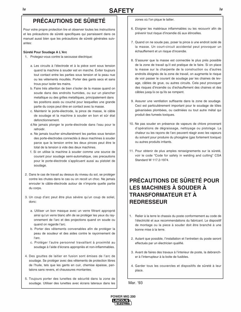
PRÉCAUTIONS DE SÛRETÉPour votre propre protection lire et observer toutes les instructionset les précautions de sûreté specifiques qui parraissent dans cemanuel aussi bien que les précautions de sûreté générales suiv-antes:
Sûreté Pour Soudage A L’Arc1. Protegez-vous contre la secousse électrique:
a. Les circuits à l’électrode et à la piéce sont sous tensionquand la machine à souder est en marche. Eviter toujourstout contact entre les parties sous tension et la peau nueou les vétements mouillés. Porter des gants secs et sanstrous pour isoler les mains.
b. Faire trés attention de bien s’isoler de la masse quand onsoude dans des endroits humides, ou sur un planchermetallique ou des grilles metalliques, principalement dans les positions assis ou couché pour lesquelles une grandepartie du corps peut être en contact avec la masse.
c. Maintenir le porte-électrode, la pince de masse, le câblede soudage et la machine à souder en bon et sûr étatdefonctionnement.
d.Ne jamais plonger le porte-électrode dans l’eau pour lerefroidir.
e. Ne jamais toucher simultanément les parties sous tensiondes porte-électrodes connectés à deux machines à souderparce que la tension entre les deux pinces peut être letotal de la tension à vide des deux machines.
f. Si on utilise la machine à souder comme une source decourant pour soudage semi-automatique, ces precautionspour le porte-électrode s’applicuent aussi au pistolet desoudage.
2. Dans le cas de travail au dessus du niveau du sol, se protégercontre les chutes dans le cas ou on recoit un choc. Ne jamaisenrouler le câble-électrode autour de n’importe quelle partiedu corps.
3. Un coup d’arc peut être plus sévère qu’un coup de soliel,donc:
a. Utiliser un bon masque avec un verre filtrant appropriéainsi qu’un verre blanc afin de se protéger les yeux du ray-onnement de l’arc et des projections quand on soude ouquand on regarde l’arc.
b. Porter des vêtements convenables afin de protéger lapeau de soudeur et des aides contre le rayonnement del‘arc.
c. Protéger l’autre personnel travaillant à proximité ausoudage à l’aide d’écrans appropriés et non-inflammables.
4. Des gouttes de laitier en fusion sont émises de l’arc desoudage. Se protéger avec des vêtements de protection libresde l’huile, tels que les gants en cuir, chemise épaisse, pan-talons sans revers, et chaussures montantes.
5. Toujours porter des lunettes de sécurité dans la zone desoudage. Utiliser des lunettes avec écrans lateraux dans les
zones où l’on pique le laitier.
6. Eloigner les matériaux inflammables ou les recouvrir afin deprévenir tout risque d’incendie dû aux étincelles.
7. Quand on ne soude pas, poser la pince à une endroit isolé dela masse. Un court-circuit accidental peut provoquer unéchauffement et un risque d’incendie.
8. S’assurer que la masse est connectée le plus prés possiblede la zone de travail qu’il est pratique de le faire. Si on placela masse sur la charpente de la construction ou d’autresendroits éloignés de la zone de travail, on augmente le risquede voir passer le courant de soudage par les chaines de lev-age, câbles de grue, ou autres circuits. Cela peut provoquerdes risques d’incendie ou d’echauffement des chaines et descâbles jusqu’à ce qu’ils se rompent.
9. Assurer une ventilation suffisante dans la zone de soudage.Ceci est particuliérement important pour le soudage de tôlesgalvanisées plombées, ou cadmiées ou tout autre métal quiproduit des fumeés toxiques.
10. Ne pas souder en présence de vapeurs de chlore provenantd’opérations de dégraissage, nettoyage ou pistolage. Lachaleur ou les rayons de l’arc peuvent réagir avec les vapeursdu solvant pour produire du phosgéne (gas fortement toxique)ou autres produits irritants.
11. Pour obtenir de plus amples renseignements sur la sûreté,voir le code “Code for safety in welding and cutting” CSAStandard W 117.2-1974.
PRÉCAUTIONS DE SÛRETÉ POURLES MACHINES À SOUDER ÀTRANSFORMATEUR ET ÀREDRESSEUR
1. Relier à la terre le chassis du poste conformement au code del’électricité et aux recommendations du fabricant. Le dispositifde montage ou la piece à souder doit être branché à unebonne mise à la terre.
2. Autant que possible, I’installation et l’entretien du poste seronteffectués par un électricien qualifié.
3. Avant de faires des travaux à l’interieur de poste, la debranch-er à l’interrupteur à la boite de fusibles.
4. Garder tous les couvercles et dispositifs de sûreté à leurplace.
Mar. ‘93
POWER MIG 200
Thank You for selecting a QUALITY product by Lincoln Electric. We want youto take pride in operating this Lincoln Electric Company product••• as much pride as we have in bringing this product to you!
Read this Operators Manual completely before attempting to use this equipment. Save this manual and keep ithandy for quick reference. Pay particular attention to the safety instructions we have provided for your protection.The level of seriousness to be applied to each is explained below:
WARNINGThis statement appears where the information must be followed exactly to avoid serious personal injury orloss of life.
This statement appears where the information must be followed to avoid minor personal injury or damage tothis equipment.
CAUTION
Please Examine Carton and Equipment For Damage ImmediatelyWhen this equipment is shipped, title passes to the purchaser upon receipt by the carrier. Consequently, Claimsfor material damaged in shipment must be made by the purchaser against the transportation company at thetime the shipment is received.
Please record your equipment identification information below for future reference. This information can befound on your machine nameplate.
Model Name & Number _____________________________________
Code & Serial Number _____________________________________
Date of Purchase _____________________________________
Whenever you request replacement parts for or information on this equipment always supply the informationyou have recorded above.
vv
vivi MASTER TABLE OF CONTENTS FOR ALL SECTIONS
Page
Installation .......................................................................................................Section ATechnical Specifications ........................................................................................A-1Safety Precautions.................................................................................................A-2Uncrating the POWER MIG 200............................................................................A-2Location .................................................................................................................A-2Input Power, Grounding and connection Diagrams .................................A-2 thru A-3Output Polarity Connections..................................................................................A-3Gun and Cable Installation ....................................................................................A-4Shielding Gas ........................................................................................................A-4
Operation .........................................................................................................Section BSafety Precautions.................................................................................................B-1Product Description ...............................................................................................B-2Recommended Processes and Equipment ...........................................................B-2Welding Capability .................................................................................................B-2Limitations..............................................................................................................B-2Description of Controls ..........................................................................................B-2Wire Drive Roll.......................................................................................................B-2Wire Size Conversion parts ...................................................................................B-2Procedure for Changing Drive Roll ........................................................................B-3Wire Reel Loading .................................................................................................B-3Mounting of 10 to 30 lbs. Spools ...........................................................................B-3To Start the Welder................................................................................................B-3Feeding Electrode..................................................................................................B-4Idle Roll Pressure Setting ......................................................................................B-4Making a Weld .......................................................................................................B-4Avoiding Wire Feeding Problems ..........................................................................B-5Fan Control ............................................................................................................B-5Input Line Voltage Protection.................................................................................B-5Wire Feed overload Protection ..............................................................................B-5Welding Thermal Overload Protection...................................................................B-5
Accessories .....................................................................................................Section CDrive Roll Kits ........................................................................................................C-1Aluminum Feeding Kit (Optional K1703-1) ............................................................C-1K363P Readi-Reel Adapter ...................................................................................C-1Dual Cylinder Mounting Kit (K1702-1) ...................................................................C-1Alternative Magnum GMAW Gun and Cable Assemblies .....................................C-1Magnum Gun Connection Kit (Optional K466-6) ...................................................C-1Spool Gun and Adapter Kit (Optional K1809-1) ....................................................C-1Making a Weld with the Spool Gun Adapter Kit and Spool Gun Installed .............C-2
POWER MIG 200
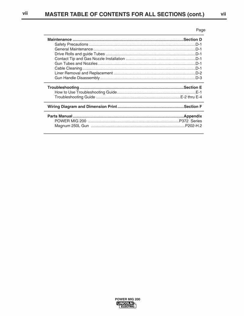
vii viiMASTER TABLE OF CONTENTS FOR ALL SECTIONS (cont.)
Page
Maintenance ....................................................................................................Section DSafety Precautions ................................................................................................D-1General Maintenance ............................................................................................D-1Drive Rolls and guide Tubes .................................................................................D-1Contact Tip and Gas Nozzle Installation ...............................................................D-1Gun Tubes and Nozzles ........................................................................................D-1Cable Cleaning......................................................................................................D-1Liner Removal and Replacement ..........................................................................D-2Gun Handle Disassembly ......................................................................................D-3
Troubleshooting ..............................................................................................Section EHow to Use Troubleshooting Guide.......................................................................E-1Troubleshooting Guide ............................................................................E-2 thru E-4
Wiring Diagram and Dimension Print ............................................................Section F
Parts Manual ....................................................................................................AppendixPOWER MIG 200 ..................................................................................P372 SeriesMagnum 250L Gun .....................................................................................P202-H.2
POWER MIG 200
A-1A-1 INSTALLATION
75°C Copper Wire 75°C Copper WireInput Ampere in Conduit in Conduit
Input Voltage/ Fuse or Breaker Rating On AWG (IEC) Sizes AWG (IEC) Sizes(For lengths (For lengths
Frequency (Hz) Size (Super Lag) Nameplate up to 100 ft.) exceeding 100 ft.)
1. Before starting the installation, check with the localpower company if there is any question aboutwhether your power supply is adequate for the volt-age, amperes, phase, and frequency specified onthe welder nameplate. Also be sure the plannedinstallation will meet the U.S. National ElectricalCode and local code requirements. This weldermay be operated from a single phase line or fromone phase of a two or three phase line.
2. Models that have multiple input voltages specifiedon the nameplate (e.g. 208/230) are shipped con-nected for the highest voltage. If the welder is to beoperated on lower voltage, it must be reconnectedaccording to the instructions in Figure A.1 for dualvoltage machines and Figure A.2 for triple voltagemachines.
Make certain that the input power is electricallydisconnected before removing the screw on thereconnect panel access cover.
Read entire installation section before startinginstallation.
SAFETY PRECAUTIONS
ELECTRIC SHOCK can kill.
• Only qualified personnel should performthis installation.
• Only personnel that have read and under-stood the POWER MIG 200 OperatingManual should install and operate thisequipment.
• Machine must be grounded per any nation-al, local or other applicable electricalcodes.
• The POWER MIG power switch is to be inthe OFF position when installing workcable and gun and when connecting otherequipment.
WARNING
UNCRATING THE POWER MIG 200
Cut banding and lift off cardboard carton. Cut bandingholding the machine to the skid. Remove foam andcorrugated packing material. Untape accessories fromGas Bottle Platform. Unscrew the two wood screws(at the Gas Bottle Platform) holding the machine tothe skid. Roll the machine off the skid assembly.
LOCATION
Locate the welder in a dry location where there is freecirculation of clean air into the louvers in the back andout the front. A location that minimizes the amount ofsmoke and dirt drawn into the rear louvers reducesthe chance of dirt accumulation that can block air pas-sages and cause overheating.
ELECTRIC SHOCK can kill.
• Do not touch electrically live parts such asoutput terminals or internal wiring.
• All input power must be electrically dis-connected before proceeding.
WARNING
WARNING
POWER MIG 200
A-3A-3 INSTALLATION
POWER MIG 200
FIGURE A.3 — Receptacle Diagram
CONNECT TO A SYSTEMGROUNDING WIRE. SEETHE UNITED STATESNATIONAL ELECTRICALCODE AND/OR LOCALCODES FOR OTHERDETAILS AND MEANS FORPROPER GROUNDING.
CONNECT TO HOT WIRESOF A THREE-WIRE, SINGLEPHASE SYSTEM OR TO ONEPHASE OF A TWO ORTHREE PHASE SYSTEM.
OUTPUT POLARITY CONNECTIONS
The welder, as shipped from the factory, is connectedfor electrode positive (+) polarity. This is the normalpolarity for GMA welding.
If negative (–) polarity is required, interchange theconnection of the two cables located in the wire drivecompartment near the front panel. The electrodecable, which is attached to the wire drive, is to be con-nected to the negative (–) labeled terminal and thework lead, which is attached to the work clamp, is tobe connected to the positive (+) labeled terminal.
50/60 HZ
FIGURE A.1 — Dual Voltage Machine Input Connections
3. The 208/230 volt 50/60 Hz model POWER MIG isshipped with a 7 ft. input cable and plug connectedto the welder.
4. Using the instructions in Figure A.3, have a quali-fied electrician connect a receptacle (CustomerSupplied) or cable to the input power lines and thesystem ground per the U.S. National ElectricalCode and any applicable local codes. See“Technical Specifications” at the beginning of thischapter for proper wire sizes. For long runs over100 feet, larger copper wires should be used. Fusethe two hot lines with super lag type fuses asshown in the following diagram. The center contactin the receptacle is for the grounding connection. Agreen wire in the input cable connects this contactto the frame of the welder. This ensures propergrounding of the welder frame when the welderplug is inserted into a grounded receptacle.
FIGURE A.3 — Receptacle Diagram
CONNECT TO A SYSTEMGROUNDING WIRE. SEE THEUNITED STATES NATIONALELECTRICAL CODE AND/ORLOCAL CODES FOR OTHERDETAILS AND MEANS FORPROPER GROUNDING.
CONNECT TO HOT WIRESOF A THREE-WIRE, SINGLEPHASE SYSTEM OR TO ONEPHASE OF A TWO ORTHREE PHASE SYSTEM.
GUN AND CABLE INSTALLATION
The Magnum 250L gun and cable provided with thePOWER MIG 200 is factory installed with a liner for.035-.045" (0.9-1.2 mm) electrode and an .035" (0.9mm) contact tip. Be sure that the contact tip, liner, anddrive rolls all match the size of the wire being used.
Turn the welder power switch off before installinggun and cable.
1. Lay the cable out straight.
2. Unscrew knurled screw on the drive unit front end(inside wire feed compartment) until tip of screw nolonger protrudes into gun opening as seen fromfront of machine.
3. Insert the male end of gun cable into the femalecasting through opening in front panel. Make sureconnector is fully inserted and tighten knurledscrew.
4. Connect the gun trigger connector from the gunand cable to the mating receptacle inside the com-partment located above the gun connection madein item 3 above. Make sure that the keyways arealigned, insert and tighten retaining ring.
SHIELDING GAS(For Gas Metal Arc Welding Processes)
Customer must provide cylinder of appropriate typeshielding gas for the process being used.
A gas flow regulator, for Argon blend gas, and an inletgas hose are factory provided with the POWER MIG200. When using 100% CO2 an additional adapter willbe required to connect the regulator to the gas bottle.
Install shielding gas supply as follows:
1. Set gas cylinder on rear platform of POWER MIG200. Hook chain in place to secure cylinder to rearof welder.
WARNING
A-4A-4 INSTALLATION
WARNING
2. Remove the cylinder cap. Inspect the cylindervalves and regulator for damaged threads, dirt,dust, oil or grease. Remove dust and dirt with aclean cloth.
DO NOT ATTACH THE REGULATOR IF OIL,GREASE OR DAMAGE IS PRESENT! Inform yourgas supplier of this condition. Oil or grease in thepresence of high pressure oxygen is explosive.
3. Stand to one side away from the outlet and openthe cylinder valve for an instant. This blows awayany dust or dirt which may have accumulated inthe valve outlet.
Be sure to keep your face away from the valveoutlet when “cracking” the valve.
4. Attach the flow regulator to the cylinder valve andtighten the union nut(s) securely with a wrench.
NOTE: If connecting to 100% CO2 cylinder, anadditional regulator adapter must be installedbetween the regulator and cylinder valve. Ifadapter is equipped with a plastic washer, be sureit is seated for connection to the CO2 cylinder.
5. Attach one end of the inlet gas hose to the outletfitting of the flow regulator, the other end to thePOWER MIG 200 rear fitting, and tighten the unionnuts securely with a wrench.
6. Before opening the cylinder valve, turn the regula-tor adjusting knob counterclockwise until theadjusting spring pressure is released.
7. Standing to one side, open the cylinder valve slow-ly a fraction of a turn. When the cylinder pressuregauge pointer stops moving, open the valve fully.
Never stand directly in front of or behind the flowregulator when opening the cylinder valve. Alwaysstand to one side.___________________________________________
8. The flow regulator is adjustable. Adjust it to theflow rate recommended for the procedure andprocess being used before making the weld.
CYLINDER may explode if damaged.
• Gas under pressure is explosive. Alwayskeep gas cylinders in an upright positionand always keep chained to undercarriageor stationary support. See AmericanNational Standard Z-49.1, “Safety inWelding and Cutting” published by theAmerican Welding Society.
WARNING
POWER MIG 200
WARNING
B-1B-1 OPERATIONRead entire Operation section beforeoperating the POWER MIG 200.
ELECTRIC SHOCK can kill.• Do not touch electrically live
parts or electrode with skin orwet clothing. Insulate yourselffrom work and ground.
• Always wear dry insulatinggloves.
FUMES AND GASES can bedangerous.• Keep your head out of fumes.
• Use ventilation or exhaust toremove fumes from breathingzone.
WELDING SPARKS cancause fire or explosion.• Keep flammable material away.
• Do not weld on closed contain-ers.
ARC RAYS can burn eyesand skin.• Wear eye, ear and body protec-
tion.
Observe all safety information throughoutthis manual.
WARNING
POWER MIG 200
B-2 B-2OPERATIONPRODUCT DESCRIPTION
The POWER MIG™ 200 is a complete semiautomaticDC voltage arc welding machine built to meet NEMAspecifications. It combines a tapped transformer volt-age power source with a constant speed wire feederto form a reliable robust performance welding system.A simple control scheme, consisting of continuous fullrange wire feed speed control, and 7 output voltagetap selections provides versatility with ease of use andaccuracy.
Other features include a 2" (51 mm) O.D. wire reelspindle with adjustable brake, an integral gas cylindermounting undercarriage, an adjustable Argon blendflow regulator with cylinder pressure gauge and inlethose, a 12 ft. (3.6 m) Magnum 250L GMAW gun andcable with fixed (flush) nozzle, a 7 ft. (2.1 m) powercable with plug, and a 10 ft. (3.0 m) work cable withclamp.
Optional Spool Gun and Adapter kit, Dual CylinderMounting kit and Aluminum Feeding Kit for push feed-ing with standard built in feeder are also available.
RECOMMENDED PROCESSES ANDEQUIPMENT
The POWER MIG 200 is recommended for GMAwelding processes using 10 to 44 lb (4.5 to 20 kg) 2"(51 mm) I.D. spools or Readi-Reel® coils (with option-al adapter) of .025" through .045" (0.6 – 1.2 mm) solidsteel, .035" (0.9 mm) stainless, 3/64" (1.2 mm) alu-minum and .045" (1.2 mm) Outershield®; as well as.035" (0.9 mm) and .045" (1.2 mm) Innershield® self-shielding electrodes.
The POWER MIG is factory equipped to feed .035"(0.9 mm) electrodes. It also includes a 200A, 60%duty cycle (or 250A, 40% duty cycle) rated, 12 ft. (3.6m) GMAW gun and cable assembly equipped forthese wire sizes. Use of GMAW processes requires asupply of shielding gas.
WELDING CAPABILITY
The POWER MIG 200 is rated at 200 amps @ 22volts, at a 30% duty cycle based on a ten minute cycletime. It is capable of higher duty cycles at lower outputcurrents. The tapped transformer design makes itwell suited for use with most portable or in-plant gen-erating systems.
LIMITATIONSThe output voltage/current of the POWER MIG 200 issubject to vary if the input power to the machinevaries, due to its tapped transformer power topology.In some cases an adjustment of WFS preset and/orvoltage tap selection may be required to accommo-date a significant drift in input power.
DESCRIPTION OF CONTROLSPower ON/OFF Switch — Place the lever in the "ON"position to energize the POWER MIG 200.Voltage Control — Seven voltage tap selections areprovided Labeled "A" (minimum voltage) through "G"(maximum voltage). It should only be adjusted whennot welding. The control selection can be preset to thesetting specified on the Procedure Decal on the insideof the wire compartment door.Wire Speed Control — This controls the wire feedspeed from 50 – 700 inches per minute (1.2 – 17.8m/min). Wire speed is not affected when changes aremade in the voltage control.
WIRE DRIVE ROLL
The drive rolls installed with the POWER MIG eachhave two grooves, both for .030-.035" (0.8-0.9 mm)solid steel electrode. Drive roll size is indicated by thestenciling on the exposed side of the drive roll. If feed-ing problems occur, then the drive roll may bereversed or changed. See "Procedure for ChangingDrive Roll" in this section.
WIRE SIZE CONVERSION PARTS
The POWER MIG 200 is rated to feed .025 through.045" (0.6-1.2 mm) solid or cored electrode sizes.The drive roll kits and Magnum 250L gun and cableparts are available to feed different sizes and types ofelectrodes. See Accessories section.
POWER MIG 200
B-3B-3 OPERATIONPROCEDURE FOR CHANGINGDRIVE AND IDLE ROLL SETS1. Turn off the power source.
2. Release the pressure on the idle roll by swingingthe adjustable pressure arm down toward the backof the machine. Lift the cast idle roll assembly andallow it to sit in an upright position..
3. Remove the outside wire guide retaining plate byloosening the two large knurled screws.
4. Twist the drive roll retaining mechanism to theunlocked position as shown below and remove thedrive roll. (See Figure A.4)
5. Remove the inside wire guide plate.
6. Replace the drive and idle rolls and inside wireguide with a set marked for the new wire size.NOTE: Be sure that the gun liner and contact tipare also sized to match the selected wire size.
7. Manually feed the wire from the wire reel, over thedrive roll groove and through the wire guide andthen into the brass bushing of the gun and cableassembly.
8. Replace the outside wire guide retaining plate bytightening the two large knurled screws. Repositionthe adjustable pressure arm to its original positionto apply pressure. Adjust pressure as necessary.
WIRE REEL LOADING - READI-REELS,SPOOLS OR COILS To Mount a 30 Lb. (14 kg) Readi-Reel Package(Using the Molded Plastic K363-P Readi-ReelAdapter:)
1. Open the Wire Drive Compartment Door
2. Depress the Release Bar on the Retaining Collar and remove it fromthe spindle.
3. Place the Optional Adapter on the spindle
4. Re-install the Retaining Collar. Make sure that the Release Bar “popsup” and that the collar retainers fully engage the retaining ring grooveon the spindle.
5. Rotate the spindle and adapter so the retaining spring is at the 12o'clock position.
6. Position the Readi-Reel so that it will rotate in a direction when feed-ing so as to be de- reeled from top of the coil.
7. Set one of the Readi-Reel inside cage wires on the slot in the retain-ing spring tab.
8. Lower the Readi-Reel to depress the retaining spring and align theother inside cage wires with the grooves in the molded adapter.
9. Slide cage all the way onto the adapter until the retaining spring"pops up" fully.
CHECK TO BE SURE THE RETAINING SPRING HAS FULLYRETURNED TO THE LOCKING POSITION AND HAS SECURELYLOCKED THE READI-REEL CAGE IN PLACE. RETAINING SPRINGMUST REST ON THE CAGE, NOT THE WELDING ELECTRODE.-----------------------------------------------------------------------------------------------10. To remove Readi-Reel from Adapter, depress retaining spring tab
with thumb while pulling the Readi-Reel cage from the moldedadapter with both hands. Do not remove adapter from spindle.
FIGURE B.1
To Mount 10 to 44 Lb. (4.5-20 kg) Spools (12"/300mm Diameter) or 14Lb.(6 Kg) Innershield Coils:
(For 13-14 lb. (6 Kg) Innershield coils, a K435 Coil Adapter must beused).
1. Open the Wire Drive Compartment Door
2. Depress the Release Bar on the Retaining Collar and remove itfrom the spindle.
3. Place the spool on the spindle making certain the spindle brakepin enters one of the holes in the back side of the spool (Note:an arrow mark on the spindle lines up with the brake holding pinto assist in lining up a hole). Be certain the wire comes off thereel in a direction so as to de-reel from the top of the coil.
4. Re-install the Retaining Collar. Make sure that the Release Bar“pops up” and that the collar retainers fully engage the retainingring groove on the spindle.
TO START THE WELDERTurn the “Power Switch” switch to “ON”. This lights the red LED dis-play lights. With the desired voltage and wire speed selected, oper-ate the gun trigger for welder output and to energize the wire feedmotor.
CAUTION
POWER MIG 200
LOCKED POSITIONUNLOCKED POSITION
FIGURE A.4
B-4B-4 OPERATIONFEEDING WIRE ELECTRODE
When triggering, the electrode and drive mecha-nism are electrically “hot” relative to work andground and remain “hot” several seconds afterthe gun trigger is released.
NOTE: Check that drive rolls, guide plates and gunparts are proper for the wire size and type being used.Refer to Table C.1 in Accessories section.
1. Turn the Readi-Reel or spool until the free end ofthe electrode is accessible.
2. While securely holding the electrode, cut off thebent end and straighten the first six inches. (If theelectrode is not properly straightened, it may notfeed properly through the wire drive system).
3. Release the pressure on the idle roll by swingingthe adjustable pressure arm down toward the backof the machine. Lift the cast idle roll assembly andallow it to sit in an upright position. Leave the outerwire guide plate installed. Manually feed the wirethrough the incoming guide bushing and throughthe guide plates (over the drive roll groove). Push asufficient wire length to assure that the wire has fedinto the gun and cable assembly without restriction.Reposition the adjustable pressure arm to its origi-nal position to apply pressure to the wire.
4. Press gun trigger to feed the electrode wirethrough the gun.
IDLE ROLL PRESSURE SETTINGThe optimum idle roll pressure varies with type ofwire, wire diameter, surface conditions, lubrication,and hardness. As a general rule, hard wires mayrequire greater pressure, and soft, or aluminum wire,may require less pressure than the factory setting.The optimum idle roll setting can be determined asfollows:1. Press end of gun against a solid object that is elec-
trically isolated from the welder output and pressthe gun trigger for several seconds.
2. If the wire “birdnests”, jams or breaks at the driveroll, the idle roll pressure is too great. Back theadjustment knob out 1/2 turn, run new wire throughgun, and repeat above steps.
3. If the only result was drive roll slippage, loosen theadjustment knob on the conductor plate and pullthe gun cable forward about 6" (15 cm). Thereshould be a slight waviness in the expose wire. Ifthere is not waviness, the pressure is too low.Tighten the adjustment knob 1/4 turn, reinstall thegun cable and repeat the above steps.
MAKING A WELD
1. Check that the electrode polarity is correct for theprocess being used, then turn the power switchON.
2. Set desired arc voltage tap and wire speed for theparticular electrode wire, material type and thick-ness, and gas (for GMAW) being used. Use theApplication Chart on the door inside the wire com-partment as a quick reference for some commonwelding procedures.
3. Press the trigger to feed the wire electrode throughthe gun and cable and then cut the electrode withinapproximately 3/8" (10 mm) of the end of the con-tact tip [3/4" (20 mm) Outershield®].
4. If welding gas is to be used, turn on the gas supplyand set the required flow rate (typically 25-35 CFH;12-16 liters/min).
5. When using Innershield electrode, the gas nozzlemay be removed from the insulation on the end ofthe gun and replaced with the gasless nozzle. Thiswill give improved visibility and eliminate the possi-bility of the gas nozzle overheating.
6. Connect work cable to metal to be welded. Workclamp must make good electrical contact to thework. The work must also be grounded as stated in“Arc Welding Safety Precautions”.
When using an open arc process, it is necessaryto use correct eye, head, and body protection.
7. Position electrode over joint. End of electrodemay be lightly touching the work.
8. Lower welding helmet, close gun trigger, andbegin welding. Hold the gun so the contact tip towork distance is about 3/8" (10 mm) [3/4" (20mm) for Outershield].
9. To stop welding, release the gun trigger and thenpull the gun away from the work after the arcgoes out.
10. When no more welding is to be done, close valveon gas cylinder (if used), momentarily operategun trigger to release gas pressure, and turn offPOWER MIG 200.
WARNING
WARNING
POWER MIG 200
B-5B-5 OPERATIONAVOIDING WIRE FEEDING PROBLEMSWire feeding problems can be avoided by observingthe following gun handling procedures:
1. Do not kink or pull cable around sharp corners.2. Keep the gun cable as straight as possible when
welding or loading electrode through cable.3. Do not allow dolly wheels or trucks to run over
cables.4. Keep cable clean by following maintenance
instructions.5. Use only clean, rust-free electrode. The Lincoln
electrodes have proper surface lubrication.6. Replace contact tip when the arc starts to become
unstable or the contact t ip end is fused ordeformed.
7. Keep wire reel spindle brake tension to minimumrequired to prevent excess reel over-travel whichmay cause wire “loop-offs” from coil.
8. Use proper drive rolls and wire drive idle roll pres-sure for wire size and type being used.
FAN CONTROLThe fan is designed to come on when input power isapplied to the POWER MIG 200 and go off whenpower is removed.
INPUT LINE VOLTAGE VARIATIONSHigh Line Voltage — Higher than rated input voltagewill result in output voltages higher than normal for agiven tap setting. If your input line is high, you maywant to select a lower voltage tap than given on therecommended procedure chart.Low Line Voltage — You may not be able to getmaximum output from the machine if the line voltageis less than rated input. The unit will continue to weld,but the output may be less than normal for a given tapsetting. If your input line is low, you may want toselect a higher voltage tap than given on the recom-mended procedure chart.
WIRE FEED OVERLOAD PROTECTIONThe POWER MIG has solid state overload protectionof the wire drive motor. If the motor becomes over-loaded, the protection circuitry turns off the wire feedspeed and gas solenoid. Check for proper size tip,liner, and drive rolls, for any obstructions or bends inthe gun cable, and any other factors that wouldimpede the wire feeding. to resume welding, simplypull the trigger. There is no circuit breaker to reset, asthe protection is done with reliable solid state elec-tronics.
WELDING THERMAL OVERLOADPROTECTIONThe POWER MIG 200 has built-in protective ther-mostats that respond to excessive temperature. Theyopen the wire feed and welder output circuits if themachine exceeds the maximum safe operating tem-perature because of a frequent overload, or highambient temperature plus overload. The thermostatsautomatically reset when the temperature reaches asafe operating level and welding and feeding areallowed again, when gun is retriggered.
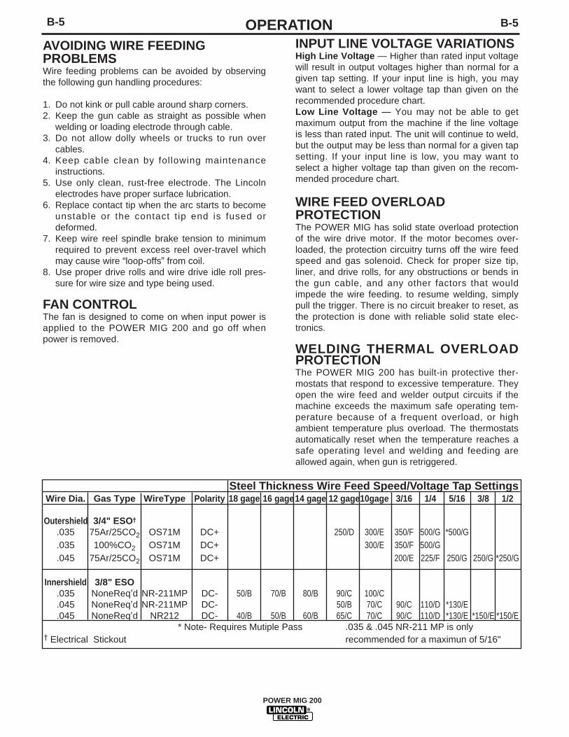
Steel Thickness Wire Feed Speed/Voltage Tap SettingsWire Dia. Gas Type WireType Polarity 18 gage 16 gage14 gage 12 gage10gage 3/16 1/4 5/16 3/8 1/2
* Note- Requires Mutiple Pass .035 & .045 NR-211 MP is only† Electrical Stickout recommended for a maximun of 5/16"
POWER MIG 200
C-1 C-1ACCESSORIESDRIVE ROLL KITS
Refer to Table C.1 for various drive roll kits that areavailable for the POWER MIG 200.The item in Bold issupplied standard with the POWER MIG 200.
TABLE C.1
3/64" (1.2 mm) ALUMINUM FEEDING KIT (K1703-1)
This kit helps push feeding aluminum through stan-dard machine feeder and gun. It provides gun andwire drive conversion parts to weld with 3/64" (1.2mm) aluminum wire. 5356 alloy aluminum wire is rec-ommended for best push feeding performance.
Kit includes drive rolls and wire guide plate for thewire drive, liner and two contact tips for the gun, alongwith installation instructions.
K363P READI-REEL ADAPTER
The K363P Readi-Reel Adapter mounts to the 2" spin-dle. It is needed to mount the 22-30 lb. Readi-Reels.
DUAL CYLINDER MOUNTING KIT(K1702-1)
Permits stable side-by-side mounting of two full size(9" dia. x 5' high) gas cylinders with “no lift” loading.Simple installation and easy instructions provided.Includes upper and lower cylinder supports, wheelaxles and mounting hardware.
ALTERNATIVE MAGNUM GMAWGUN AND CABLE ASSEMBLIES
The following Magnum 250L gun and cable assem-blies are separately available for use with the POWERMIG 200. Each is rated 200 amps 60% duty cycle andis equipped with the integrated connector, twist-locktrigger connector, fixed nozzle and insulator, andincludes a liner, diffuser, and contact tips for the wiresizes specified:
MAGNUM GUN CONNECTION KIT(Optional K466-6)
Using the optional K466-6 Magnum Connection kit forthe POWER MIG permits use of standard Magnum200, 300 or 400 gun and cable assemblies.
SPOOL GUN AND ADAPTER KIT (K1809-1)The K1809-1includes the Magnum 250SG Spool gunand the adapter kit for connecting the spool gun to thePower MIG 200.
The Adapter Kit provides toggle switch selectionbetween the machine’s use with its feeder gun or thespool gun for same polarity welding with different wireand gas processes.
The kit includes a spool gun adapter module assem-bly with a single connecting plug and trigger switch, arear gas inlet, fitting hose, solenoid valve assembly,and mounting hardware with installation and operationinstructions.
Remove all input power to the POWER MIG 200before installing the Spool Gun and Kit.
10' (3.0 m) K533-112' (3.6 m) K533-2 .035 – .045" 0.9 – 1.2 mm15' (4.5 m) K533-3
10' *3.0 m) K533-412' (3.6 m) K533-5 .025 – .030" 0.6 – 0.8 mm15' (4.5 m) K533-6
WARNING
POWER MIG 200
C-2C-2 ACCESSORIESMAKING A WELD WITH THE SPOOL GUNADAPTER KIT AND SPOOL GUNINSTALLED
In either toggle switch position, closing either guntrigger will cause the electrode of both guns to beelectrically “HOT”. Be sure unused gun is posi-tioned so electrode or tip will not contact metalcase or other metal common to work.
1. Setting spool gun selector switch to the “Normal”position and pulling the trigger for the built-in feed-er gun.
• Disables spool gun operation and spool gungas solenoid valve.
• Closing feeder gun trigger starts feeder gunwelding and makes both electrodes electrically“HOT”.
2. Setting spool gun selector switch to the Spool GunPosition and pulling SPOOL GUN Trigger.
• Disables built-in feeder gun operation andmachine gas solenoid valve.
• Enables spool gun operation and spool gun gassolenoid valve.
• Closing spool gun trigger starts spool gun weld-ing and makes both electrodes electrically“HOT”.
3. Operation with POWER MIG 200:
• Turn the POWER MIG-200 input power ON.
• Adjusting the voltage tap control will increase ordecrease your welding voltage.
• Adjusting the wire speed control on the spoolgun will increase or decrease the spool gunwire feed speed. NOTE: Adjusting the wire feedspeed control on the Power Mig Panel has noaffect on the spool gun’s wire feed speed.
4. Refer to the procedure decal on the Power Mig forinitial aluminum settings. Make a test weld to deter-mine the final settings.
5. To return to normal POWER MIG 200 welding,release the spool gun trigger set spool gun selectorswitch to normal and reset feeder gun voltage pro-cedure setting if necessary.
CAUTION
POWER MIG 200
D-1D-1 MAINTENANCECONTACT TIP AND GAS NOZZLEINSTALLATION1. Choose the correct size contact tip for the elec-
trode being used (wire size is stenciled on the sideof the contact tip) and screw it snugly into the gasdiffuser.
2. Screw the appropriate fixed gas nozzle fully ontothe diffuser. Either the standard .50" (12.7 mm)flush nozzle or other optional flush or recessed(spray arc) nozzle sizes may be used. (See TableD.2 in this section.)
3. If using optional adjustable slip-on nozzles, seeTable D.2 in this section.
• Be sure the nozzle insulator is fully screwedonto the gun tube and does not block the gasholes in the diffuser.
• Slip the appropriate gas nozzle onto the nozzleinsulator. Either a standard .50" (12.7 mm) oroptional .62" (15.9 mm) I.D. slip-on gas nozzlemay be used and should be selected based onthe welding application.
* Adjust the gas nozzle as appropriate for theGMAW process to be used. Typically, the con-tact tip end should be flush to .12" (3.2 mm)extended for the short-circuiting transferprocess and .12" (3.2 mm) recessed for spraytransfer.
GUN TUBES AND NOZZLES
1. Replace worn contact tips as required.
2. Remove spatter from inside of gas nozzle andfrom tip after each 10 minutes of arc time or asrequired.
GUN CABLE CLEANING
To help prevent feeding problems, clean cable linerafter using approximately 300 pounds (136 kg) ofelectrode. Remove the cable from the wire feederand lay it out straight on the floor. Remove the con-tact tip from the gun. Using an air hose and only par-tial pressure, gently blow out the cable liner from thegas diffuser end.
SAFETY PRECAUTIONS
ELECTRIC SHOCK can kill.• Have an electrician install and
service this equipment.
• Turn the input power off at thefuse box before working onequipment
• Do not touch electrically hotparts.
GENERAL MAINTENANCE
In extremely dusty locations, dirt may clog the air pas-sages causing the welder to run hot. Blow dirt out ofthe welder with low-pressure air at regular intervals toeliminate excessive dirt and dust build-up on internalparts.
The fan motors have sealed ball bearings whichrequire no service.
DRIVE ROLLS AND GUIDE PLATES
After every coil of wire, inspect the wire drive mecha-nism. Clean it as necessary by blowing with low pres-sure compressed air. Do not use solvents for cleaningthe idle roll because it may wash the lubricant out ofthe bearing. All drive rolls are stamped with the wiresizes they will feed. If a wire size other than thatstamped on the roll is used, the drive roll must bechanged.
For instructions on replacing or changing drive roll,see “Wire Drive Rolls” in Operation section.
WARNING
POWER MIG 200
D-2D-2 MAINTENANCE4. Insert a new untrimmed liner into the connector
end of the cable. Be sure the liner bushing is sten-cilled appropriately for the wire size bing used.
5. Fully seat the liner bushing into the connector.tighten the set screw on the brass cable connector.the gas diffuser, at this time, should not beinstalled onto the end of the gun tube.
6. With the gas diffusor still removed from the guntube, be sure the cable is straight, and then trimthe l iner to the length shown in Figure D.1.Remove any burrs from the end of the liner.
7. Screw the gas diffuser onto the end of the gun tubeand securely tighten. Be sure the gas diffuser iscorrect for the liner being used. (See table and dif-fuser stencil.)
8. Tighten the set screw in the side of the gas diffuseragainst the cable liner using a 5/64" (2.0 mm) Allenwrench.
FIGURE D.1
This screw should only be gently tightened.Overtightening will split or collapse the liner andcause poor wire feeding.
Excessive pressure at the start may cause the dirtto form a plug.
Flex the cable over its entire length and again blowout the cable. Repeat this procedure until no furtherdirt comes out. If this has been done and feed prob-lems are experienced, try liner replacement, and referto trouble shooting section on rough wire feeding.
LINER REMOVAL AND REPLACE-MENT
NOTE: Changing the liner for a different wire sizerequires replacement of the gas diffuser per Table D.1to properly secure the different liner.
LINER REMOVAL, INSTALLATION AND TRIMMINGINSTRUCTIONS FOR MAGNUM 250L
NOTE: The variation in cable lengths prevents theinterchangeability of liners between guns. Once a linerhas been cut for a particular gun, it should not beinstalled in another gun unless it can meet the linercutoff length requirement. Liners are shipped with thejacket of the liner extended the proper amount.
1. Remove the gas nozzle and nozzle insulator, ifused, to locate the set screw in the gas diffuserwhich is used to hold the old liner in place. Loosenthe set screw with a 5/64" (2.0 mm) Allen wrench.
2. Remove the gas diffuser from the gun tube.
3. Lay the gun and cable out straight on a flat surface.Loosen the set screw located in the brass connec-tor at the feeder end of the cable and pull the linerout of the cable.
CAUTION
Fixed AdjustableNozzle Nozzle
Replacement Size Stencilled Gas Diffuser Gas DiffuserDiameter of Liner Part on End of Part No. Part No.Electrodes Used Number Liner Bushing (and Stencil) (and Stencil)
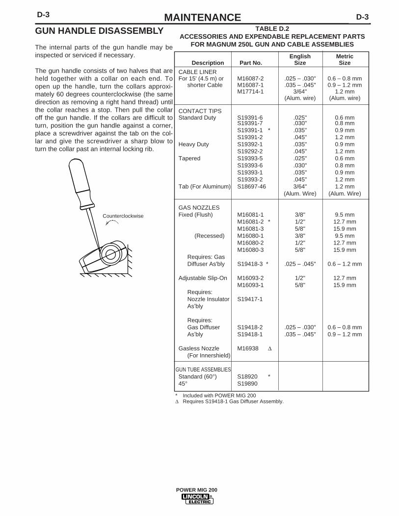
The internal parts of the gun handle may beinspected or serviced if necessary.
The gun handle consists of two halves that areheld together with a collar on each end. Toopen up the handle, turn the collars approxi-mately 60 degrees counterclockwise (the samedirection as removing a right hand thread) untilthe collar reaches a stop. Then pull the collaroff the gun handle. If the collars are difficult toturn, position the gun handle against a corner,place a screwdriver against the tab on the col-lar and give the screwdriver a sharp blow toturn the collar past an internal locking rib.
Counterclockwise
➣
English MetricDescription Part No. Size Size
CABLE LINERFor 15' (4.5 m) or M16087-2 .025 – .030" 0.6 – 0.8 mm
TABLE D.2ACCESSORIES AND EXPENDABLE REPLACEMENT PARTS
FOR MAGNUM 250L GUN AND CABLE ASSEMBLIES
* Included with POWER MIG 200Δ Requires S19418-1 Gas Diffuser Assembly.
POWER MIG 200
E-1E-1 TROUBLESHOOTING
POWER MIG 200
If for any reason you do not understand the test procedures or are unable to perform the tests/repairs safely, contact yourLocal Lincoln Authorized Field Service Facility for technical troubleshooting assistance before you proceed.
CAUTION
This Troubleshooting Guide is provided to help youlocate and repair possible machine malfunctions.Simply follow the three-step procedure listed below.
Step 1. LOCATE PROBLEM (SYMPTOM).Look under the column labeled “PROBLEM (SYMP-TOMS)”. This column describes possible symptomsthat the machine may exhibit. Find the listing thatbest describes the symptom that the machine isexhibiting.
Step 2. POSSIBLE CAUSE.The second column labeled “POSSIBLE CAUSE” liststhe obvious external possibilities that may contributeto the machine symptom.
Step 3. RECOMMENDED COURSE OF ACTIONThis column provides a course of action for thePossible Cause, generally it states to contact yourlocal Lincoln Authorized Field Service Facility.
If you do not understand or are unable to perform theRecommended Course of Action safely, contact yourlocal Lincoln Authorized Field Service Facility.
HOW TO USE TROUBLESHOOTING GUIDE
Service and Repair should only be performed by Lincoln Electric Factory Trained Personnel.Unauthorized repairs performed on this equipment may result in danger to the technician andmachine operator and will invalidate your factory warranty. For your safety and to avoid ElectricalShock, please observe all safety notes and precautions detailed throughout this manual.
There is no wire feed or open cir-cuit voltage when the gun trigger ispulled. Input power is applied toPOWER MIG 200.
Output voltage and wire feed is pre-sent when gun trigger is not pulled(not activated).
Machine output is low. Welds are“cold”, weld bead is rounded orbumped up demonstrating poorwetting into plate.
POSSIBLE AREAS OFMISADJUSTMENT
1. Contact your Local LincolnAuthorized Field Service Facility.
1 The gun trigger or cable may befaulty. Check or replace gunassembly.
2. The thermal protection circuitmay be activated. If this is thecase allowing the machine tocool will clear the error condition.
3. Make sure input voltage is cor-rect and matches nameplate rat-ing and reconnect panel configu-ration.
4. If spool gun option kit is installed, check to see that it is setto “Normal” if pulling the gun trig-ger associated with built in feed-er, and “Spool Gun” if pullingspool gun trigger.
1. Remove gun assembly frommachine. If problem is solvedgun assembly is faulty. Repair orreplace.
2. If problem persists when gunassembly is removed frommachine then the problem iswithin the POWER MIG 200.
1. Check input voltage. Make sureinput voltage matches name-plate rating and reconnect panelconfiguration.
2. Make sure settings for wire feedspeed and voltage are correctfor process being used.
3. Make sure output polarity is cor-rect for process being used.
4. Check welding cables and gunassembly for loose or faulty con-nections.
RECOMMENDEDCOURSE OF ACTION
If all recommended possible areasof misadjustment have beenchecked and the problem persists,Contact your local LincolnAuthorized Field Service Facility.
OUTPUT PROBLEMS
If for any reason you do not understand the test procedures or are unable to perform the tests/repairs safely, contact yourLOCAL AUTHORIZED LINCOLN ELECTRIC FIELD SERVICE FACILITY for assistance before you proceed.
CAUTION
POWER MIG 200
Observe all Safety Guidelines detailed throughout this manual
E-3E-3 TROUBLESHOOTING
PROBLEMS(SYMPTOMS)
1. Poor arc striking with electrodesticking or blasting off.
POSSIBLE AREAS OFMISADJUSTMENT
1. Make sure settings for wire feedspeed and voltage are correctfor process being used.
2. The gas shielding may beimproper for process being used.
3. Check imput line voltage to bewith in machines recommendedrating range.
4. Check that the machine recon-nect panel is configured properlyfor the applied voltage.
RECOMMENDEDCOURSE OF ACTION
If all recommended possible areasof misadjustment have beenchecked and the problem persists,Contact your local LincolnAuthorized Field Service Facility.
OUTPUT PROBLEMS
If for any reason you do not understand the test procedures or are unable to perform the tests/repairs safely, contact yourLOCAL AUTHORIZED LINCOLN ELECTRIC FIELD SERVICE FACILITY for assistance before you proceed.
CAUTION
PROBLEMS(SYMPTOMS)1. Rough wire feeding or wire will
not feed but drive rolls are turn-ing.
1. The wire feed stops while weld-ing. When trigger is releasedand pulled again the wire feedstarts.
1. No control of wire feed speed.Other machine functions are nor-mal.
POSSIBLE AREAS OFMISADJUSTMENT(S)1. The gun cable may be kinked or twisted.
2. The wire may be jammed in the guncable, or gun cable may be dirty.
3. Check drive roll tension andposition of grooves.
4. Check for worn or loose drive rolls.
5. The electrode may be rusty or dirty.
6. Check for damaged or incorrectcontact tip.
7. Check wire spindle for ease ofrotation and adjust break ten-sion knob if necessary.
8. Check that the gun is pushed allthe way into gun mount andproperly seated.
1. Check the wire feed drive rollsand motor for smooth operation.
2. Check for restrictions in the wirefeed path. Check the gun andcable for restrictions.
3. Make sure gun liner and tip arecorrect for wire size being used.
4. Make sure drive rolls and guide platesare clean and are the correct size.
5. Check spindle for ease of rotation.
1. The wire feed speed control maybe dirty. Rotate several timesand check if problem is resolved.
RECOMMENDEDCOURSE OF ACTION
If all recommended possible areasof misadjustment have beenchecked and the problem persists,Contact your local LincolnAuthorized Field Service Facility.
FEEDING PROBLEMS
POWER MIG 200
Observe all Safety Guidelines detailed throughout this manual
E-4 E-4TROUBLESHOOTING
PROBLEMS(SYMPTOMS)
Gas does not flow when gun triggeris pulled.
POSSIBLE AREAS OFMISADJUSTMENT(S)
1. Make sure gas supply is con-nected properly and turned “on”.
2. If the gas solenoid does actuate(click) when the gun trigger ispulled there may be a restrictionin the gas supply line.
3. The gun cable assembly may befaulty. Check or replace.
4. If gas solenoid does not operatewhen gun trigger is pulled theproblem is within the POWERMIG 200.
5. Make sure the gun is pushed allthe way into gun mount and isproperly seated.
RECOMMENDEDCOURSE OF ACTION
If all recommended possible areasof misadjustment have beenchecked and the problem persists,Contact your local LincolnAuthorized Field Service Facility.
GAS FLOW PROBLEMS
If for any reason you do not understand the test procedures or are unable to perform the tests/repairs safely, contact yourLOCAL AUTHORIZED LINCOLN ELECTRIC FIELD SERVICE FACILITY for assistance before you proceed.
CAUTION
POWER MIG 200
Observe all Safety Guidelines detailed throughout this manual
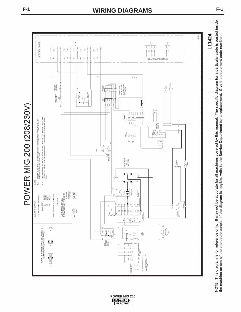
F-1F-1 WIRING DIAGRAMS
NO
TE
: T
his
dia
gra
m is
fo
r re
fere
nce
onl
y.
It m
ay n
ot
be
accu
rate
fo
r al
l mac
hine
s co
vere
d b
y th
is m
anua
l. T
he s
pec
ific
dia
gra
m f
or
a p
artic
ular
co
de
is p
aste
d in
sid
eth
e m
achi
ne o
n o
ne o
f th
e en
clo
sure
pan
els.
If
the
dia
gra
m is
ille
gib
le, w
rite
to
the
Ser
vice
Dep
artm
ent
for
a re
pla
cem
ent.
Giv
e th
e eq
uip
men
t co
de
num
ber
..
POWER MIG 200
PO
WE
R M
IG 2
00 (
208/
230V
)
L114
2410-2
000
J1
CA
VIT
Y N
UM
BE
RIN
G S
EQ
UE
NC
E(C
OM
PO
NE
NT
SID
E O
F P
.C.
BO
AR
D)
J2
NO
TES:
N.A
.W
ELD
ING
CAB
LE M
UST
BE
OF
PRO
PER
CAP
ACIT
Y FO
R T
HE
CU
RR
ENT
AND
DU
TY C
YCLE
OF
IMM
EDIA
TE A
ND
FU
TUR
E AP
PLIC
ATIO
NS.
N.B
.TH
IS D
IAG
RAM
SH
OW
S TH
E "E
LEC
TRO
DE"
PO
LAR
ITY
“PO
SITI
VE”.
TO
CH
ANG
E PO
LAR
ITY,
TU
RN
THE
UN
IT O
FF A
ND
REV
ERSE
LEA
D C
ON
NEC
TIO
NS
AT C
ABLE
CO
ND
UC
TOR
STR
AP A
ND
WO
RK
STU
D.
1
72 3 4 5 6 81
J1
10 11 129
H5
H1
B
103
A
113
A1
09A
108A
116A
116
B
10
6B
X10
114A
10
6A
109
A
108
A
10
7A
106
A
105
A
104
A
103
A
102
A
10
4B
10
1A
X9
X9
-
+
BR
IDG
ED
IOD
ER
EC
TIF
IER
MO
UN
TE
DB
AF
FLE
TR
AN
SF
OR
ME
RT
HE
RM
OS
TA
T
RE
CT
IFIE
RA
SS
EM
BL
YT
HE
RM
OS
TA
T
G F E D C B A
X10
X9
B W
CO
NT
AC
TO
R
H5
FA
NM
OT
OR
X5X7
X827.
8V
X6
SIN
GLE
PH
ASE
BRID
GE
REC
TIFI
ER
21
432
TR
IGG
ER
GU
N
CO
NT
RO
L B
OA
RD
P.M
.
R2
X1
TR
AN
SF
OR
ME
RP
OW
ER
H2
X3
W
CH
OK
EO
UT
PU
T
B
X2
H1
230V
H1
H4
50
W4
0 O
HM
S
50V
31
,000
MF
DC
1 A
ND
C2
++
C2
SU
PP
LY L
INE
TO
SIN
GLE
PH
AS
E
L1L2
63
L1
4 5
J2
X4
C1
H2
GP
AN
EL
RE
CO
NN
EC
T
S1
SW
ITC
HL
INE
H1
208V
L2
B
SP
EE
DW
IRE
FE
ED
H3
GE
AR
BO
XM
OT
OR
/
WO
RK
TO
R1
H3
H4
324
325
W
CO
DE
NA
TIO
NA
L E
LEC
TR
ICA
LT
O G
RO
UN
D P
ER
FOR SPOOL GUN OPTION
J3
1 2J3
1 432
J5**
110
A
111
A
1 432
JUM
PER
PLU
GIN
STAL
LED
FO
RN
ON
-SPO
OL
GUN
OPE
RATI
ON
PA
GAS
SOLE
NO
ID
107A
106C
106B
106C
116B
105A
105B
113
A
1 432
1 432
65
T A C H
115A
R BU
R BU
J4**
9
PA
J4 (
TR
IGG
ER
,
TA
CH
OM
ET
ER
,
MO
TO
R S
IDE
)
GEN
ERAL
INFO
RM
ATIO
N
ELEC
TRIC
AL S
YMBO
LS P
ER E
1537
CO
LOR
CO
DE
B -
BLAC
KW
-W
HIT
ER
-R
EDU
-BL
UE
IND
ICAT
ES C
ON
NEC
TOR
CAV
ITY
No.
** C
AVIT
Y
NU
MBE
RIN
G S
EQU
ENC
E(N
ON
-LEA
D S
IDE
OF
CO
NN
ECTO
R)
8 16
1
46
13
8
14
5
1 2
87
65
65
13 14 15 16
10
4C
104C
104D
104D
111A
11
2A
101A
102A
114
A
115
A
105B
112A
46
13
104
A
116
A
-+
TA
P S
ELE
CT
OR
SW
ITC
H
F-2F-2 DIMENSION PRINT
3-00
F
M19
231
POWER MIG 200
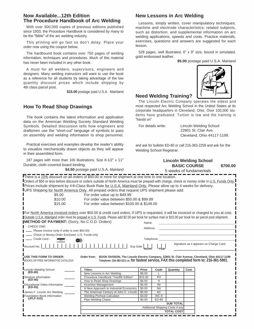
Now Available...12th EditionThe Procedure Handbook of Arc Welding
With over 500,000 copies of previous editions publishedsince 1933, the Procedure Handbook is considered by many to be the “Bible” of the arc welding industry.
This printing wil l go fast so don ’t delay. Place your order now using the coupon below.
The hardbound book contains over 750 pages of weldinginformation, techniques and procedures. Much of this material has never been included in any other book.
A must for al l welders, supervisors, engineers anddesigners. Many welding instructors will want to use the bookas a reference for all students by taking advantage of the lowquantity discount prices which include shipping by4th class parcel post.
$15.00 postage paid U.S.A. Mainland
How To Read Shop Drawings
The book contains the latest information and applicationdata on the American Welding Society Standard WeldingSymbols. Detailed discussion tells how engineers anddraftsmen use the “short-cut” language of symbols to passon assembly and welding information to shop personnel.
Practical exercises and examples develop the reader’s abilityto visualize mechanically drawn objects as they will appearin their assembled form.
187 pages with more than 100 illustrations. Size 8-1/2” x 11”Durable, cloth-covered board binding.
$4.50 postage paid U.S.A. Mainland
New Lessons in Arc WeldingLessons, simply written, cover manipulatory techniques;
machine and electrode characteristics; related subjects,such as distortion; and supplemental information on arcwelding applications, speeds and costs. Practice materials,exercises, questions and answers are suggested for each lesson.
528 pages, well illustrated, 6” x 9” size, bound in simulated,gold embossed leather.
$5.00 postage paid U.S.A. Mainland
Need Welding Training?The Lincoln Electric Company operates the oldest and
most respected Arc Welding School in the United States at itscorporate headquarters in Cleveland, Ohio. Over 100,000 stu-dents have graduated. Tuit ion is low and the training is “hands on”
For details write: Lincoln Welding School22801 St. Clair Ave. Cleveland, Ohio 44117-1199.
and ask for bulletin ED-80 or call 216-383-2259 and ask for theWelding School Registrar.
Lincoln Welding SchoolBASIC COURSE $700.00
5 weeks of fundamentalsThere is a 10% discount on all orders of $50.00 or more for shipment at one time to one location.Orders of $50 or less before discount or orders outside of North America must be prepaid with charge, check or money order in U.S. Funds Only.Prices include shipment by 4 th Class Book Rate for U.S.A. Mainland Only. Please allow up to 4 weeks for delivery.UPS Shipping for North America Only. All prepaid orders that request UPS shipment please add:
$5.00 For order value up to $49.99$10.00 For order value between $50.00 & $99.99$15.00 For order value between $100.00 & $149.00
For North America invoiced orders over $50.00 & credit card orders, if UPS is requested, it will be invoiced or charged to you at cost.Outside U.S.A. Mainland order must be prepaid in U.S. Funds. Please add $2.00 per book for surface mail or $15.00 per book for air parcel post shipment.METHOD OF PAYMENT: (Sorry, No C.O.D. Orders)
Signature as it appears on Charge Card:Account No. |_|_|_|_|_|_|_|_|_|_|_|_|_|_|_|_|_|_|_|_|_| Exp Date |_|_| |_|_| ______________________Month Year
USE THIS FORM TO ORDER: Order from: BOOK DIVISION, The Lincoln Electric Company, 22801 St. Clair Avenue, Cleveland, Ohio 44117-1199BOOKS OR FREE INFORMATIVE CATALOGS Telephone: 216-383-2211 or, for fastest service, FAX this completed form to: 216-361-5901.
Lincoln Welding School Titles: Price Code Quantity Cost(ED-80) New Lessons in Arc Welding $5.00 L
Seminar Information Procedure Handbook “Twelfth Edition” $15.00 PH(ED-45) How to Read Shop Drawings $4.50 H
Educational Video Information Incentive Management $5.00 IM(ED-93) A New Approach to Industrial Economics $5.00 NA
James F. Lincoln Arc Welding The American Century of John C. Lincoln $5.00 ACFoundation Book Information Welding Preheat Calculator $3.00 WC-8
(JFLF-515) Pipe Welding Charts $4.50 ED-89SUB TOTAL
Additional Shipping Costs if anyTOTAL COST
MasterCard
VISA ®
AMERICAN EXPRESS
MasterCardMasterCard®
AMERICAN EXPRESS
WARNING
AVISO DEPRECAUCION
ATTENTION
WARNUNG
ATENÇÃO
Spanish
French
German
Portuguese
Japanese
Chinese
Korean
Arabic
READ AND UNDERSTAND THE MANUFACTURER’S INSTRUCTION FOR THIS EQUIPMENT AND THE CONSUMABLES TO BEUSED AND FOLLOW YOUR EMPLOYER’S SAFETY PRACTICES.
SE RECOMIENDA LEER Y ENTENDER LAS INSTRUCCIONES DEL FABRICANTE PARA EL USO DE ESTE EQUIPO Y LOSCONSUMIBLES QUE VA A UTILIZAR, SIGA LAS MEDIDAS DE SEGURIDAD DE SU SUPERVISOR.
LISEZ ET COMPRENEZ LES INSTRUCTIONS DU FABRICANT EN CE QUI REGARDE CET EQUIPMENT ET LES PRODUITS AETRE EMPLOYES ET SUIVEZ LES PROCEDURES DE SECURITE DE VOTRE EMPLOYEUR.
LESEN SIE UND BEFOLGEN SIE DIE BETRIEBSANLEITUNG DER ANLAGE UND DEN ELEKTRODENEINSATZ DES HER-STELLERS. DIE UNFALLVERHÜTUNGSVORSCHRIFTEN DES ARBEITGEBERS SIND EBENFALLS ZU BEACHTEN.
● Do not touch electrically live parts orelectrode with skin or wet clothing.
● Insulate yourself from work andground.
● No toque las partes o los electrodosbajo carga con la piel o ropa moja-da.
● Aislese del trabajo y de la tierra.
● Ne laissez ni la peau ni des vête-ments mouillés entrer en contactavec des pièces sous tension.
● Isolez-vous du travail et de la terre.
● Berühren Sie keine stromführendenTeile oder Elektroden mit IhremKörper oder feuchter Kleidung!
● Isolieren Sie sich von denElektroden und dem Erdboden!
● Não toque partes elétricas e elec-trodos com a pele ou roupa molha-da.
● Isole-se da peça e terra.
● Keep flammable materials away.
● Mantenga el material combustiblefuera del área de trabajo.
● Gardez à l’écart de tout matérielinflammable.
● Entfernen Sie brennbarres Material!
● Mantenha inflamáveis bem guarda-dos.
● Wear eye, ear and body protection.
● Protéjase los ojos, los oídos y elcuerpo.
● Protégez vos yeux, vos oreilles etvotre corps.
● Tragen Sie Augen-, Ohren- und Kör-perschutz!
● Use proteção para a vista, ouvido ecorpo.
WARNING
AVISO DEPRECAUCION
ATTENTION
WARNUNG
ATENÇÃO
Spanish
French
German
Portuguese
Japanese
Chinese
Korean
Arabic
LEIA E COMPREENDA AS INSTRUÇÕES DO FABRICANTE PARA ESTE EQUIPAMENTO E AS PARTES DE USO, E SIGA ASPRÁTICAS DE SEGURANÇA DO EMPREGADOR.
● Keep your head out of fumes.● Use ventilation or exhaust to
remove fumes from breathing zone.
● Los humos fuera de la zona de res-piración.
● Mantenga la cabeza fuera de loshumos. Utilice ventilación oaspiración para gases.
● Gardez la tête à l’écart des fumées.● Utilisez un ventilateur ou un aspira-
teur pour ôter les fumées des zonesde travail.
● Vermeiden Sie das Einatmen vonSchweibrauch!
● Sorgen Sie für gute Be- undEntlüftung des Arbeitsplatzes!
● Mantenha seu rosto da fumaça.● Use ventilação e exhaustão para
remover fumo da zona respiratória.
● Turn power off before servicing.
● Desconectar el cable de ali-mentación de poder de la máquinaantes de iniciar cualquier servicio.
● Débranchez le courant avant l’entre-tien.
● Strom vor Wartungsarbeitenabschalten! (Netzstrom völlig öff-nen; Maschine anhalten!)
● Não opere com as tampas removidas.● Desligue a corrente antes de fazer
serviço.● Não toque as partes elétricas nuas.
● Do not operate with panel open orguards off.
● No operar con panel abierto oguardas quitadas.
● N’opérez pas avec les panneauxouverts ou avec les dispositifs deprotection enlevés.
● Anlage nie ohne Schutzgehäuseoder Innenschutzverkleidung inBetrieb setzen!
● Mantenha-se afastado das partesmoventes.
● Não opere com os paineis abertosou guardas removidas.
• Sales and Service through Subsidiaries and Distributors Worldwide •