Image Image Deconvolution Deconvolution Applied to CCD astronomical Applied to CCD astronomical images images with astrometric purposes with astrometric purposes Maria Teresa Merino Espasa Universidad de Barcelona (Spain)
Transcript
Image Deconvolution Image Deconvolution
Applied to CCD astronomical Applied to CCD astronomical imagesimages
with astrometric purposeswith astrometric purposes
Maria Teresa Merino EspasaUniversidad de Barcelona (Spain)
SummarySummary
Introduction to Image Restoration Adaptative deconvolution with wavelets Applications of our deconvolution
algorithm with astrometric purposes: Increase of faint detections in Baker-Nunn images for
faint asteroid discovering Quest aplication to increase astrometrical resolution
to detect gravitational lenses candidates Work in progress to increse faint detection + increase
astrometrical resolution
Conclusions
1. Introduction to image 1. Introduction to image RestorationRestoration
Objective:Presentation of our algorithm for MLE deconvolution in linear space-invariant PSF systems with complete basic CCD images statistics (Poisson + Gaussian)
Image restorationImage restoration
atmosphere effects optical distorsions and aberrations different pixel sensitivity additional noise (in emision, travelling and/or
detection) …
Our detected data images are not exactly the radiation from sources of interest. It’s important to consider that may be affected by:
Image Restoration is the removal or reduction of those degradations that were incurred while the digital image was being obtained to bring the image toward what it would have been if it had been recorded without degradation.In astronomy, the most usual objectives are: deblurring
removal atmospheric seeing radiationimage sharpeningfusion of data from diferent instrumentsincrease S/N of sourcesastrometric resolution improvement…
Linear image formation system with additive Linear image formation system with additive noisenoise
),(),(),( yxnyxgyxp p(x,y): projection (measured) data
When When space-invariant PSFspace-invariant PSF::
),(),(),(·),(),( 111111 yxdyxhdydxyxdyyxxhyxg
),(),(),(),( yxnyxdyxhyxp
In Fourier In Fourier Space:Space: ),(),()·,(),( vuNvuDvuHvuP
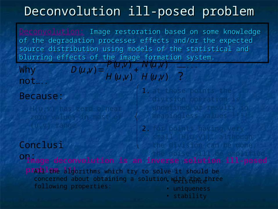
Deconvolution ill-posed problemDeconvolution ill-posed problem
Why not…..
),(),(
),(),(
),(vuHvuN
vuHvuP
vuD ……...
?
Because:H(u,v) has zero o near zero values in most of (u,v) range
1. at those points the division operation is undefined or results in meaningless values !!!!
2. for points having very small |H(u,v)|, although the division can be done, the noise will be amplified to an intorelable extent !!!!
Conclusion:Image deconvolution is an inverse solution ill-posed
problem !!!All the algorithms which try to solve it should be concerned about obtaining a solution with the three following properties:• existence
• uniqueness• stability
Deconvolution: Image restoration based on some knowledge of the Image restoration based on some knowledge of the degradation processes effects and/or the expected source distribution degradation processes effects and/or the expected source distribution using models of the statistical and blurring effects of the image using models of the statistical and blurring effects of the image formation system.formation system.
Deconvolution algorithmsDeconvolution algorithms
1. Image formation, degradation and recovering model basic hypotesis
Classical approach:• Direct inverse filter in Fourier space• Linear Regularized Filters (Wiener)• Minimum root mean squares• CLEAN
4. Iteration Stopping protocol (a posteriori, feasibility tests, crossvalidation maximum,…)
The Bayesian Approach The Bayesian Approach (fixed (fixed models)models)
)(
)()|()|(
p
aappa
P(a|p): “a posterior probability”, radiation a given the recorded data p
P(a): “a prior probability” of the source of radiation
P(p|a): likelihood
P(p): Normalizing constant
• MAP (Maximum A Posteriori), maximizes P(p|a)·P(a)
• MLE (Maximum Likelihood Estimator), maximizes P(p|a) with P(a)=cte
• MEM (Maximum Entropy Method) is MAP with p(a) given by maximum entropy hypotesis (=minimum data uncertainty)
Bayes Hypotesis:Bayes Hypotesis: The most probable image a(x,y), given The most probable image a(x,y), given measured data p(x,y) is obtained by maximizing P(a|p) with a measured data p(x,y) is obtained by maximizing P(a|p) with a suposed P(p|a) image formation model (and maybe also a suposed P(p|a) image formation model (and maybe also a P(a) “a priory” knowledge).P(a) “a priory” knowledge).
The most usual deconvolution algorithms division regarding how they maximize P(a|p) are:
G+P_MLE deconvolutionG+P_MLE deconvolution
• sucessive sustitutions convergence method
• energy conservation:
• Poisson photon gathering+Gauss readout noise:
0
2
)(
0
2
)(
!
)(
!
)(
'2
2
2
2
k
kj
pk
k
kj
pk
j
k
he
k
hke
pj
j
!
j
k
jhj
hP k h e
k
NOTE: This resulting algorithm, without flat and background, is similar to MLE Poisson (Richardson Lucy) computation structure if p’=p and K=1
Iterative and nonlinear algorithm
2
2
2
)(
2
1)|(
kp
j
j
ekpP
B
iji
j
ijj ba
C
fh
1
·
m
D
jjj
B
l
sljl
jji
i
si
si
bCaf
pf
qaa
1
1
)(
)()1( '1
B
i
m
D
jjj
B
l
sljl
jjisi
D
jjj
s
bCaf
pfa
bp
1 1
1
)(
)(
1)(
'
)(
AlgorithAlgorithmmbasics:basics:
D
jj
D
jj
B
i
B
i
D
j
ijiii bp
Cj
afaq
111 1 1
2. Adaptative 2. Adaptative Deconvolution with Deconvolution with
WaveletsWavelets
Objective:Presentation of our multiresolution adaptative deconvolution algorithm based on wavelets
Wavelets descompositionWavelets descompositionThe wavelet transform replaces the Fourier transform’s sinusoidal waves The wavelet transform replaces the Fourier transform’s sinusoidal waves
by a family generated by by a family generated by translationstranslations and and dilationsdilations of a function called of a function called
Mother WaveletMother Wavelet. .
General properties of wavelets descomposition: Spatial and frequential content is almost decoupled. Better noise vs.signal discrimination than Fourier transform. Good processing flexibility.
Discrete wavelet transform (DWT) algorithm specific properties: DWT is computed with à trous algorithm.
Mother wavelet function is derived from a B3 cubic spline scaling function.
This is a dyadic decomposition (scale 2i , i=1,...,n). No subsampling is applied wavelet planes have same size as original image.
- space and scale
- base
functions
)(, xbab a
dxxfabafWT abx )()()),(( 2
1
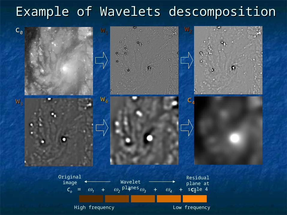
Example of Wavelets descompositionExample of Wavelets descomposition
co 1 2 3 4 c4 = + + + + Wavelet planes
High frequency Low frequency
Original image
Residual plane at scale 4
cc00 ww11
cc44ww33ww44
ww22
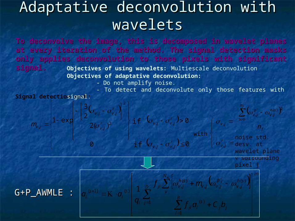
Adaptative deconvolution with Adaptative deconvolution with waveletswavelets
Signal detection mask:
with
Objectives of using wavelets: Multiescale deconvolutionObjectives of adaptative deconvolution:
- Do not amplify noise. - To detect and deconvolute only those features with signal.
To deconvolve the image, this is decomposed in wavelet planes at every To deconvolve the image, this is decomposed in wavelet planes at every iteration of the method. The signal detection masks only applies iteration of the method. The signal detection masks only applies deconvolution to those pixels with significant signal.deconvolution to those pixels with significant signal.
m
D
jjj
B
l
sljl
N
v
shjv
pjvjv
shjvji
i
si
si
bCaf
mf
qaa
wj
1
1
)(
)(,
',,
)(,
)()1( 1
0
)(2
2
3
exp12
,
2
,,
,r
jv
rjvjv
jvm
f
n
t
shjv
pjv
jv n
f
2)(,
',
,
rjv,
noise std. desv. at wavelet plane sorrounding pixel j
if 0,, rjvjv
if 0,, rjvjv
G+P_AWMLE G+P_AWMLE ::
3. Applications of our 3. Applications of our deconvolution algorithm with deconvolution algorithm with
astrometric purposes:astrometric purposes:
Objective:Show astrometric objectives, aplications and deconvolution artifacts and effects
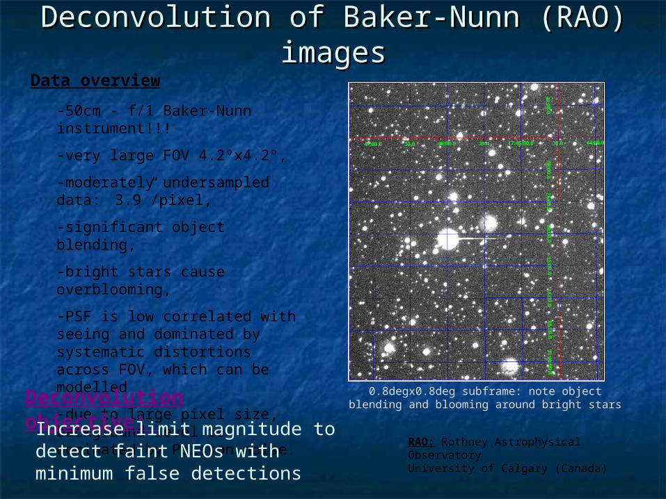
-50cm - f/1 Baker-Nunn instrument!!!
-very large FOV 4.2ºx4.2º,
-moderately undersampled data: 3.9”/pixel,
-significant object blending,
-bright stars cause overblooming,
-PSF is low correlated with seeing and dominated by systematic distortions across FOV, which can be modelled
-due to large pixel size, background level is dominated by Poisson noise.
Data overview
0.8degx0.8deg subframe: note object blending and blooming around bright starsDeconvolution objective:
Increase limit magnitude to detect faint NEOs with minimum false detections
RAO: Rothney Astrophysical ObservatoryUniversity of Calgary (Canada)
Deconvolution of Baker-Nunn (RAO) Deconvolution of Baker-Nunn (RAO) imagesimages
Protocol for Baker-Nunn imagesProtocol for Baker-Nunn images
7) Compute limiting magnitude gain and rest of
analysis
1) CCD image calibration: bias, dark and flatfield correction
2) Compute astrometric plate transformation with reference catalogue
3) Perform aperture photometry of selected stars (bright but not saturated)
4) PSF fitting with list created in 3)
6) sextractor object detection and matching with USNOA2.0 catalogue
iraf.ccdproc
wcstools.sua2, sextractor,iraf.ccmap
iraf.phot, iraf.pstselect
iraf.psf, iraf.seepsf
5) Image deconvolution
Deconvolution of Baker-Nunn imagesDeconvolution of Baker-Nunn images
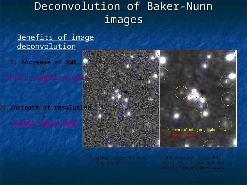
Benefits of image deconvolution
1) Increase of SNR
Limiting magnitude gain
2) Increase of resolution
Object deblending
Original image: in blue matched detections
Deconvoluted image 60 iterations: yellow and red are new matched
detections
Matched vs. non-matched detections
Evolution of raw and matched detections with the number of iterations.Asymptotic converge translated into stable number of detections for large number of iterations.
Adaptative wavelet deconvolution introduces small number of non-matched detections. In contrast to classical Richardson-Lucy algorithms, false detections increase linearly, not exponentially.
Deconvolution of Baker-Nunn imagesDeconvolution of Baker-Nunn images
Where do the non-matched detections come from?
Left: original image with explanation of the origin of non-matched detections displayed in red in the right frame, which corresponds to a 60 iteration deconvoluted image.
Deconvolution of Baker-Nunn imagesDeconvolution of Baker-Nunn images
Limiting magnitude gain
USNOA2.0 R magnitude distribution for the catalogue itself (top), deconvoluted image 180 iterations (middle) and original
image (bottom)
But deriving magnitude gain directly from ratio of the number of detections is not allways reliable, due to intrinsic magnitude distribution of studied stellar field.
From estimating the completeness of magnitude histograms with respect to
USNOA2.0 distribution:
mR 0.6
Image# matched detections
Original 1559
Deconvoluted 180 iterations
2365
Deconvolution of Baker-Nunn imagesDeconvolution of Baker-Nunn images
Deconvolution of QUEST imagesDeconvolution of QUEST images
V filter, frames from 2 CCDs 1”/pixel, 2 diferent fields in 2 single CCDs Limiting magnitude (S/N>10)
aprox. 19.2
Data overview
Deconvolution objective:
Detect a subsample of QSO candidates likely to be lensed by:
1. improving the resolution (deblend close companions)
2. improving the limiting magnitude
2 MiniMosaic WIYN 0.141”/pixel Covers aprox. the same field 6+38 QSO candidates detected by
varability criteria in those fields
QUEST= QUasar Ecuatorial Survey Team
QUEST images to deconvolve
WIYN images to evaluate results
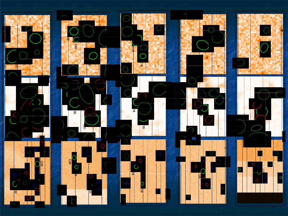
Aplication of image deconvolution to 6 QSO candidates in the field. Each panel includes original QUEST image, deconvolved QUEST (400 iterations) and high resolution WIYN image, repectively. Those in green correspond to objecte present in all three images, in black those only resolved by WIYN and in red those resolved in both deconvolved QUEST and WIYN.
Deconvolution of QUEST imagesDeconvolution of QUEST images
Algorithm propertiesAlgorithm properties Powerful technique for increasing the number of useful
science objects from the faint part of magnitude distribution.
Low speed convergence and heavy CPU and RAM usage.
Cheap: only requires fast computers. The algorithm is highly parallelizable to be run in distributed computers.
Generalizable for whatever observing facility employing a CCD.
Enhances spatial resolution which translates into better object deblending discrimination.
Systematic usage best suited for astrometric surveys with moderate data throughput.
Selective usage is suited for all kind of images, either high or low resolution.
Work in progressWork in progress
Use multi frame reduction for removing cosmics and hot pixels.
Improve PSF fitting to decrease false detections around bright stars.
Compare internal astrometric accuracy of original and deconvoluted images.
Accurate determination of CCD flats, gain and readout noise for better noise distribution modelling when deconvoluting.
Define strategy to assess space variant PSF across the FOV
Further evaluation of astrometric improvements and photometric effects.
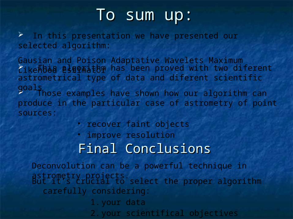
To sum up:To sum up:
Deconvolution can be a powerful technique in astrometry projects.
Those examples have shown how our algorithm can produce in the particular case of astrometry of point sources:
• recover faint objects• improve resolution
In this presentation we have presented our selected algorithm:
Gausian and Poison Adaptative Wavelets Maximum Likehood Estimator This algorithm has been proved with two diferent astrometrical type of data and diferent scientific goals
But it’s crucial to select the proper algorithm carefully considering: