713 Image Formation by Mirrors and Lenses CHAPTER OUTLINE 26.1 Images Formed by Flat Mirrors 26.2 Images Formed by Spherical Mirrors 26.3 Images Formed by Refraction 26.4 Thin Lenses 26.5 Context ConnectionMedical Fiberscopes ANSWERS TO QUESTIONS Q26.1 With a concave spherical mirror, for objects beyond the focal length the image will be real and inverted. For objects inside the focal length, the image will be virtual, upright, and magnified. Try a shaving or makeup mirror as an example. Q26.2 With a convex spherical mirror, all images of real objects are upright, virtual, and smaller than the object. As seen in Question 26.1, you only get a change of orientation when you pass the focal point—but the focal point of a convex mirror is on the non-reflecting side! Q26.3 The mirror equation and the magnification equation apply to plane mirrors. A curved mirror is made flat by increasing its radius of curvature without bound, so that its focal length goes to infinity. From 1 1 1 0 p q f + = = we have 1 1 p q =− ; therefore, p q =− . The virtual image is as far behind the mirror as the object is in front. The magnification is M q p p p =− = = 1 . The image is right side up and actual size. Q26.4 Stones at the bottom of a clear stream always appear closer to the surface because light is refracted away from the normal at the surface. Example 26.5 in the textbook shows that its apparent depth is three quarters of its actual depth. Q26.5 For definiteness, we consider real objects ( p > 0 ). (a) For M q p =− to be negative, q must be positive. This will happen in 1 1 1 q f p = − if p f > , if the object is farther than the focal point. (b) For M q p =− to be positive, q must be negative. From 1 1 1 q f p = − we need p f < . continued on next page
Transcript
713
Image Formation byMirrors and Lenses
CHAPTER OUTLINE 26.1 Images Formed by Flat
Mirrors 26.2 Images Formed by
Spherical Mirrors 26.3 Images Formed by
Refraction 26.4 Thin Lenses 26.5 Context
ConnectionMedical Fiberscopes
ANSWERS TO QUESTIONS Q26.1 With a concave spherical mirror, for objects beyond the focal length
the image will be real and inverted. For objects inside the focal length, the image will be virtual, upright, and magnified. Try a shaving or makeup mirror as an example.
Q26.2 With a convex spherical mirror, all images of real objects are upright, virtual, and smaller than the
object. As seen in Question 26.1, you only get a change of orientation when you pass the focal point—but the focal point of a convex mirror is on the non-reflecting side!
Q26.3 The mirror equation and the magnification equation apply to plane mirrors. A curved mirror is
made flat by increasing its radius of curvature without bound, so that its focal length goes to infinity.
From 1 1 1
0p q f
+ = = we have 1 1p q
= − ; therefore, p q= − . The virtual image is as far behind the mirror
as the object is in front. The magnification is Mqp
pp
= − = = 1 . The image is right side up and actual
size. Q26.4 Stones at the bottom of a clear stream always appear closer to the surface because light is refracted
away from the normal at the surface. Example 26.5 in the textbook shows that its apparent depth is three quarters of its actual depth.
Q26.5 For definiteness, we consider real objects (p > 0 ).
(a) For Mqp
= − to be negative, q must be positive. This will happen in 1 1 1q f p
= − if p f> , if the
object is farther than the focal point.
(b) For Mqp
= − to be positive, q must be negative.
From 1 1 1q f p
= − we need p f< .
continued on next page
714 Image Formation by Mirrors and Lenses
(c) For a real image, q must be positive.
As in part (a), it is sufficient for p to be larger than f. (d) For q < 0 we need p f< . (e) For M > 1, we consider separately M < −1 and M > 1.
If Mqp
= − < −1, we need qp
> 1 or q p>
or 1 1q p
< .
From 1 1 1p q f
+ = , 1 1 1p p f
+ > or 2 1p f
>
or p
f2
< or p f< 2 .
Now if − >qp
1 or − >q p or q p< −
we may require q < 0 , since then 1 1 1p f q
= − with 1
0f
>
gives 1 1p q
> − as required or − >p q.
For q < 0 in 1 1 1q f p
= − we need p f< .
Thus the overall condition for an enlarged image is simply p f< 2 . (f) For M < 1 , we have the reverse of part (e), requiring p f> 2 .
Q26.6 Using the same analysis as in Question 26.5 except f < 0 .
(a) Never. (b) Always. (c) Never, for light rays passing through the lens will always diverge. (d) Always. (e) Never. (f) Always.
Chapter 26 715
Q26.7 We assume the lens has a refractive index higher than its surroundings. For the biconvex lens in
Figure 26.20(a), R1 0> and R2 0< . Then all terms in nR R
− −FHG
IKJ1
1 1
1 2a f are positive and f > 0 . For the
other two lenses in part (a) of the figure, R1 and R2 are both positive but R1 is less than R2 . Then 1 1
1 2R R> and the focal length is again positive.
For the biconcave lens and the plano-concave lens in Figure 26.20(b), R1 0< and R2 0> . Then
both terms are negative in 1 1
1 2R R− and the focal length is negative. For the middle lens in part (b)
of the figure, R1 and R2 are both positive but R1 is greater than R2 . Then 1 1
1 2R R< and the focal
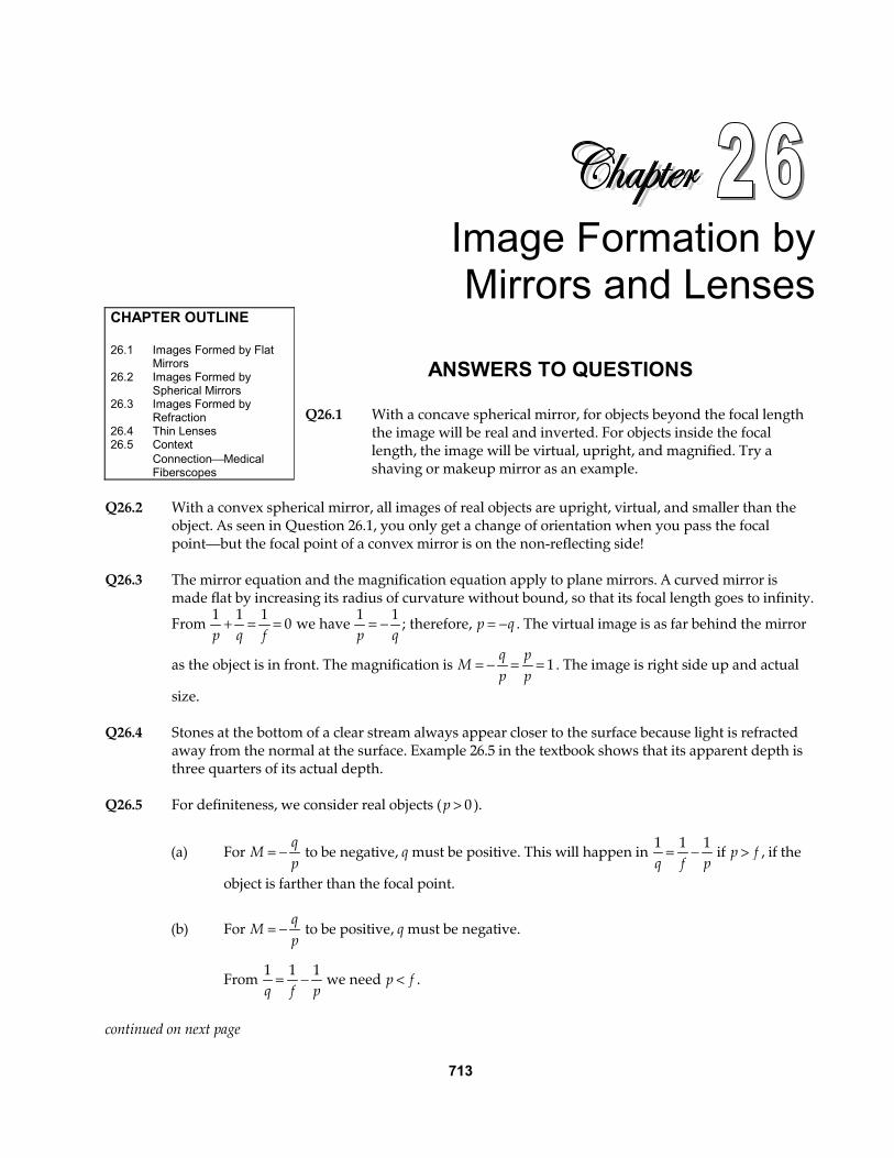
length is again negative. Q26.8 Both words are inverted. However OXIDE has up-down symmetry whereas LEAD does not. Q26.9 In the diagram, only two of the three principal rays have
been used to locate images to reduce the amount of visual clutter. The upright shaded arrows are the objects, and the correspondingly numbered inverted arrows are the images. As you can see, object 2 is closer to the focal point than object 1, and image 2 is farther to the left than image 1. I
V
FC
O1 O2
1I2
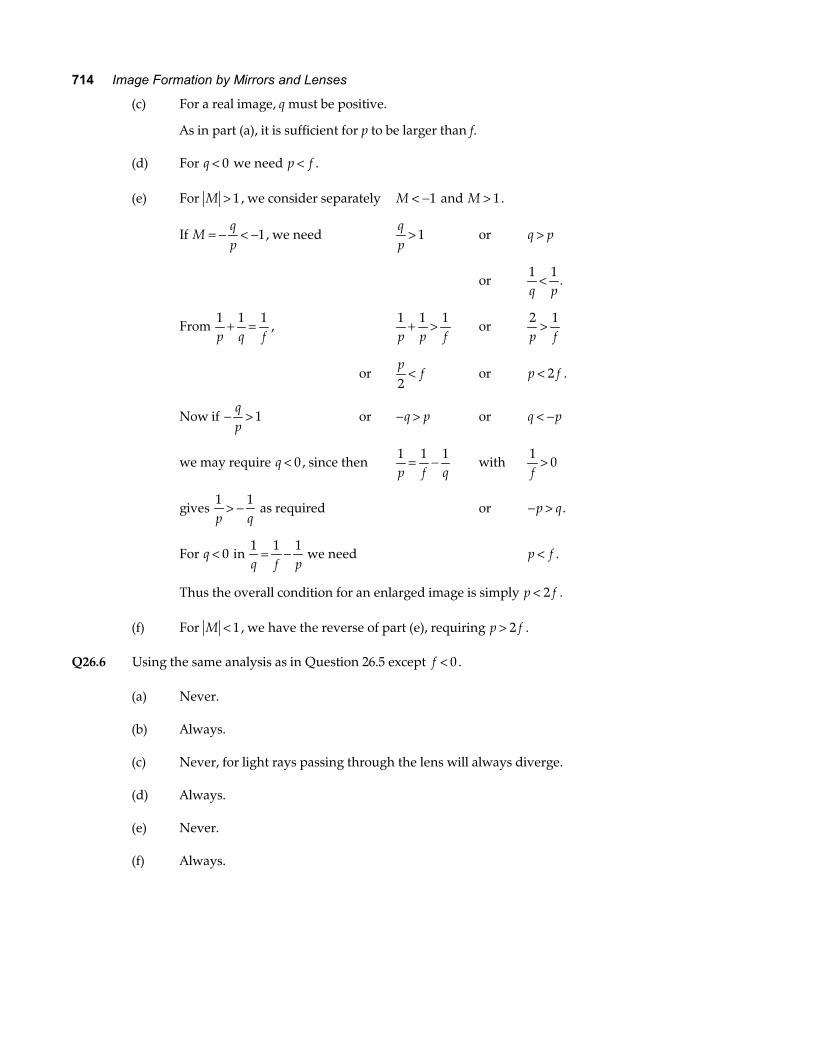
FIG. Q26.9 Q26.10 As in the diagram, let the center of curvature C of the fishbowl
and the bottom of the fish define the optical axis, intersecting the fishbowl at vertex V. A ray from the top of the fish that reaches the bowl surface along a radial line through C has angle of incidence zero and angle of refraction zero. This ray exits from the bowl unchanged in direction. A ray from the top of the fish to V is refracted to bend away from the normal. Its extension back inside the fishbowl determines the location of the image and the characteristics of the image. The image is upright, virtual, and enlarged.
C O IV
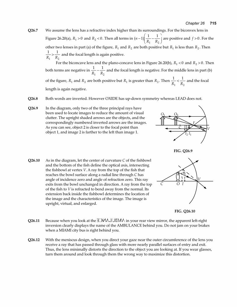
FIG. Q26.10 Q26.11 Because when you look at the in your rear view mirror, the apparent left-right
inversion clearly displays the name of the AMBULANCE behind you. Do not jam on your brakes when a MIAMI city bus is right behind you.
Q26.12 With the meniscus design, when you direct your gaze near the outer circumference of the lens you
receive a ray that has passed through glass with more nearly parallel surfaces of entry and exit. Thus, the lens minimally distorts the direction to the object you are looking at. If you wear glasses, turn them around and look through them the wrong way to maximize this distortion.
716 Image Formation by Mirrors and Lenses
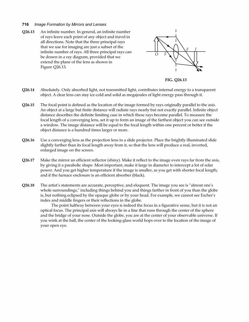
Q26.13 An infinite number. In general, an infinite number of rays leave each point of any object and travel in all directions. Note that the three principal rays that we use for imaging are just a subset of the infinite number of rays. All three principal rays can be drawn in a ray diagram, provided that we extend the plane of the lens as shown in Figure Q26.13.
IO F
F
FIG. Q26.13 Q26.14 Absolutely. Only absorbed light, not transmitted light, contributes internal energy to a transparent
object. A clear lens can stay ice-cold and solid as megajoules of light energy pass through it. Q26.15 The focal point is defined as the location of the image formed by rays originally parallel to the axis.
An object at a large but finite distance will radiate rays nearly but not exactly parallel. Infinite object distance describes the definite limiting case in which these rays become parallel. To measure the focal length of a converging lens, set it up to form an image of the farthest object you can see outside a window. The image distance will be equal to the focal length within one percent or better if the object distance is a hundred times larger or more.
Q26.16 Use a converging lens as the projection lens in a slide projector. Place the brightly illuminated slide
slightly farther than its focal length away from it, so that the lens will produce a real, inverted, enlarged image on the screen.
Q26.17 Make the mirror an efficient reflector (shiny). Make it reflect to the image even rays far from the axis,
by giving it a parabolic shape. Most important, make it large in diameter to intercept a lot of solar power. And you get higher temperature if the image is smaller, as you get with shorter focal length; and if the furnace enclosure is an efficient absorber (black).
Q26.18 The artist’s statements are accurate, perceptive, and eloquent. The image you see is “almost one’s
whole surroundings,” including things behind you and things farther in front of you than the globe is, but nothing eclipsed by the opaque globe or by your head. For example, we cannot see Escher’s index and middle fingers or their reflections in the globe.
The point halfway between your eyes is indeed the focus in a figurative sense, but it is not an optical focus. The principal axis will always lie in a line that runs through the center of the sphere and the bridge of your nose. Outside the globe, you are at the center of your observable universe. If you wink at the ball, the center of the looking-glass world hops over to the location of the image of your open eye.
Chapter 26 717
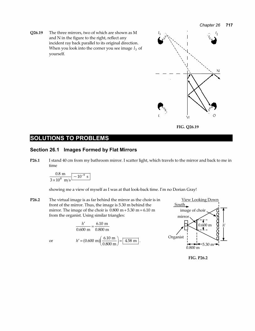
Q26.19 The three mirrors, two of which are shown as M and N in the figure to the right, reflect any incident ray back parallel to its original direction. When you look into the corner you see image I3 of yourself.
FIG. Q26.19
SOLUTIONS TO PROBLEMS Section 26.1 Images Formed by Flat Mirrors P26.1 I stand 40 cm from my bathroom mirror. I scatter light, which travels to the mirror and back to me in
time
0 8
3 10108
9.~
m m s
s×
−
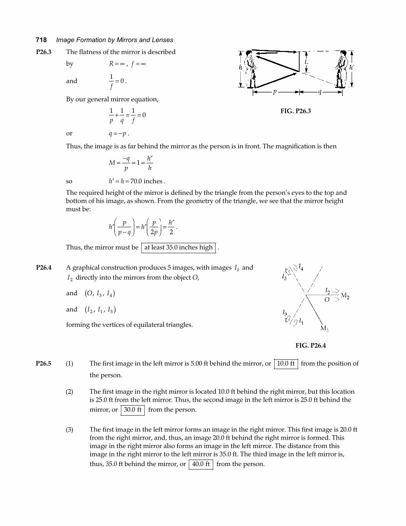
showing me a view of myself as I was at that look-back time. I’m no Dorian Gray! P26.2 The virtual image is as far behind the mirror as the choir is in
front of the mirror. Thus, the image is 5.30 m behind the mirror. The image of the choir is 0 800 5 30 6 10. . .m m m+ = from the organist. Using similar triangles:
′ =h
0 6006 10
..
m m
0.800 m
or ′ = FHG
IKJ =h 0 600
6 104 58.
.. m
m0.800 m
ma f .
h'
Southimage of choir
mirror
0.600 m
5.30 m0.800 m
Organist
View Looking Down
FIG. P26.2
718 Image Formation by Mirrors and Lenses
P26.3 The flatness of the mirror is described
by R = ∞ , f = ∞
and 1
0f
= .
By our general mirror equation,
1 1 1
0p q f
+ = =
or q p= − .
FIG. P26.3
Thus, the image is as far behind the mirror as the person is in front. The magnification is then
Mq
phh
=−
= = ′1
so ′ = =h h 70 0. inches .
The required height of the mirror is defined by the triangle from the person’s eyes to the top and bottom of his image, as shown. From the geometry of the triangle, we see that the mirror height must be:
′−FHGIKJ = ′FHGIKJ =
′h
pp q
hpp
h2 2
.
Thus, the mirror must be at least 35.0 inches high .
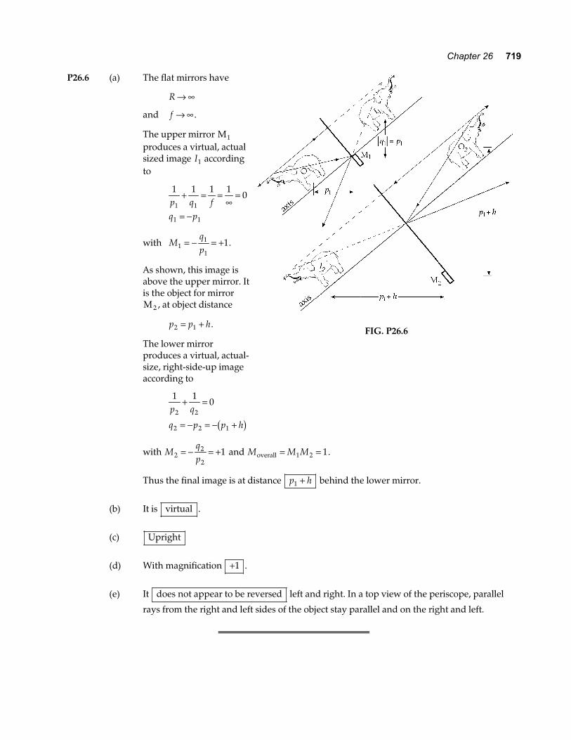
P26.4 A graphical construction produces 5 images, with images I1 and
I2 directly into the mirrors from the object O,
and O I I, ,3 4b g
and I I I2 1 5, ,b g
forming the vertices of equilateral triangles.
FIG. P26.4
P26.5 (1) The first image in the left mirror is 5.00 ft behind the mirror, or 10 0. ft from the position of
the person. (2) The first image in the right mirror is located 10.0 ft behind the right mirror, but this location
is 25.0 ft from the left mirror. Thus, the second image in the left mirror is 25.0 ft behind the mirror, or 30 0. ft from the person.
(3) The first image in the left mirror forms an image in the right mirror. This first image is 20.0 ft
from the right mirror, and, thus, an image 20.0 ft behind the right mirror is formed. This image in the right mirror also forms an image in the left mirror. The distance from this image in the right mirror to the left mirror is 35.0 ft. The third image in the left mirror is, thus, 35.0 ft behind the mirror, or 40 0. ft from the person.
Chapter 26 719
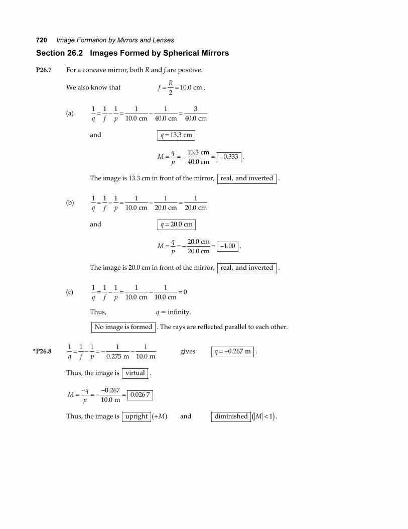
P26.6 (a) The flat mirrors have
R → ∞
and f → ∞ .
The upper mirror M1 produces a virtual, actual sized image I1 according to
1 1 1 1
01 1
1 1
p q fq p
+ = =∞
=
= −
with Mqp1
1
11= − = + .
As shown, this image is above the upper mirror. It is the object for mirror M 2 , at object distance
p p h2 1= + .
The lower mirror produces a virtual, actual-size, right-side-up image according to
FIG. P26.6
1 10
2 2
2 2 1
p q
q p p h
+ =
= − = − +b g
with Mqp2
2
21= − = + and M M Moverall = =1 2 1.
Thus the final image is at distance p h1 + behind the lower mirror.
(b) It is virtual .
(c) Upright
(d) With magnification +1 .
(e) It does not appear to be reversed left and right. In a top view of the periscope, parallel
rays from the right and left sides of the object stay parallel and on the right and left.
720 Image Formation by Mirrors and Lenses
Section 26.2 Images Formed by Spherical Mirrors P26.7 For a concave mirror, both R and f are positive.
We also know that fR= =2
10 0. cm .
(a) 1 1 1 1
10 01
40 03
40 0q f p= − = − =
. . . cm cm cm
and q = 13 3. cm
Mqp
= = − = −13 30 333
..
cm40.0 cm
.
The image is 13.3 cm in front of the mirror, real, and inverted .
(b) 1 1 1 1
10 01
20 01
20 0q f p= − = − =
. . . cm cm cm
and q = 20 0. cm
Mqp
= = − = −20 01 00
..
cm20.0 cm
.
The image is 20.0 cm in front of the mirror, real, and inverted .
(c) 1 1 1 1
10 01
10 00
q f p= − = − =
. . cm cm
Thus, q = infinity.
No image is formed . The rays are reflected parallel to each other.
*P26.8 1 1 1 1
0 2751
10 0q f p= − = − −
. . m m gives q = −0 267. m .
Thus, the image is virtual .
Mq
p=
−= − − =0 267
10 00 026 7
..
. m
Thus, the image is upright +Ma f and diminished M < 1c h .
Chapter 26 721
P26.9 (a) 1 1 2p q R
+ = gives 1
30 01 2
40 0. . cm cm+ =
−q a f
1 2
40 01
30 00 083 3 1
q= − − = − −
. ..
cm cm cm so q = −12 0. cm
Mq
p=
−= −
−=
12 030 0
0 400.
..
cm cm
a f.
(b) 1 1 2p q R
+ = gives 1
60 01 2
40 0. . cm cm+ =
−q a f
1 2
40 01
60 00 066 6 1
q= − − = − −
. ..
cm cm cm so q = −15 0. cm
Mq
p=
−= −
−=
15 060 0
0 250.
..
cm cm
a f.
(c) Since M > 0 , the images are upright .
P26.10 With radius 2.50 m, the cylindrical wall is a highly efficient mirror for sound, with focal length
fR= =2
1 25. m .
In a vertical plane the sound disperses as usual, but that radiated in a horizontal plane is concentrated in a sound image at distance q from the back of the niche, where
1 1 1p q f
+ = so 1
2 001 1
1 25. . m m+ =
q
q = 3 33. m .
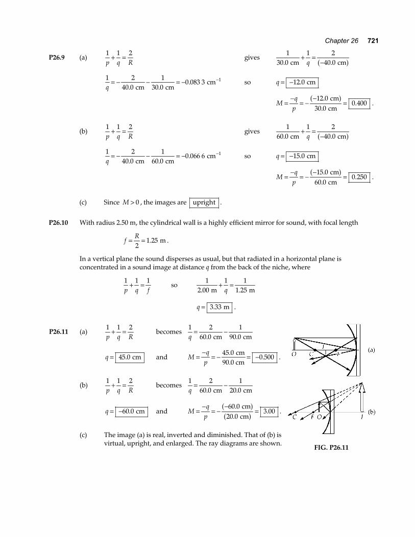
P26.11 (a) 1 1 2p q R
+ = becomes 1 2
60 01
90 0q= −
. . cm cm
q = 45 0. cm and Mq
p=
−= − = −45 0
0 500.
. cm
90.0 cm.
(b) 1 1 2p q R
+ = becomes 1 2
60 01
20 0q= −
. . cm cm
q = −60 0. cm and Mq
p=
−= −
−=
60 020 0
3 00.
..
cm cm
a fa f .
(c) The image (a) is real, inverted and diminished. That of (b) is
virtual, upright, and enlarged. The ray diagrams are shown. FIG. P26.11
722 Image Formation by Mirrors and Lenses
*P26.12 (a) Since the object is in front of the mirror, p > 0 . With the image behind the mirror, q < 0. The
mirror equation gives the radius of curvature as 2 1 1 1
1 001
10 010 1
10 0R p q= + = − = −
. . . cm cm cm, or
R = FHGIKJ = +2
10 09
2 22.
. cm
cm .
(b) The magnification is Mqp
= − = −−
= +10 0
1 0010 0
..
. cm
cma f
.
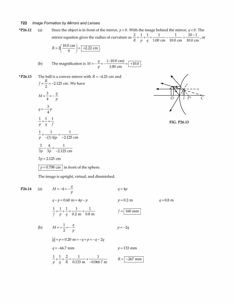
*P26.13 The ball is a convex mirror with R = −4 25. cm and
fR= = −2
2 125. cm. We have
Mqp
= = −34
q p= − 34
1 1 1p q f
+ =
1 1
3 41
2 125p p+
−=
−b g . cm
3
34
31
2 125p p− =
− . cm
3 2 125p = . cm
p = 0 708. cm in front of the sphere.
The image is upright, virtual, and diminished.
O I F C
FIG. P26.13
P26.14 (a) Mqp
= − = −4 q p= 4
q p p p− = = −0 60 4. m p = 0 2. m q = 0 8. m
1 1 1 1
0 21
0 8f p q= + = +
. . m m f = 160 mm
(b) Mqp
= + = −12
p q= −2
q p q p q q+ = = − + = − −0 20 2. m
q = −66 7. mm p = 133 mm
1 1 2 1
0 1331
0 066 7p q R+ = = +
−. . m m R = −267 mm
Chapter 26 723
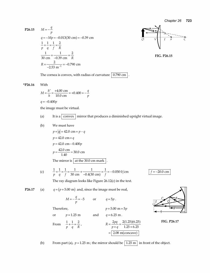
P26.15 Mqp
= −
q Mp
p q f R
R
R
= − = − = −
+ = =
+−
=
=−
= −−
0 013 30 0 391 1 1 2
130
10 39
2
22 53
0 7901
. .
.
..
cm cm
cm cm
m cm
a f
FIG. P26.15
The cornea is convex, with radius of curvature 0 790. cm .
*P26.16 With
Mhh
qp
= ′ = + = + = −4 000 400
..
cm10.0 cm
q p= −0 400.
the image must be virtual.
(a) It is a convex mirror that produces a diminished upright virtual image. (b) We must have
p q p q+ = = −42 0. cm
p q= +42 0. cm
p p= −42 0 0 400. .cm
p = =42 030 0
..
cm1.40
cm
The mirror is at the 30.0 cm mark .
(c) 1 1 1 1
301
0 4 301
0 050 0p q f f
+ = = +−
= = − cm cm
cm.
.a f f = −20 0. cm
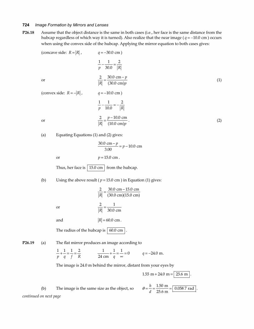
The ray diagram looks like Figure 26.12(c) in the text. P26.17 (a) q p= + 5 00. mb g and, since the image must be real,
Mqp
= − = −5 or q p= 5 .
Therefore, p p+ =5 00 5. m
or p = 1 25. m and q = 6 25. m .
From 1 1 2p q R
+ = , Rpq
p q=
+=
+
=
2 2 1 25 6 251 25 6 25
2 08
. .. .
.
a fa f
a f m concave
FIG. P26.17
(b) From part (a), p = 1 25. m ; the mirror should be 1 25. m in front of the object.
724 Image Formation by Mirrors and Lenses
P26.18 Assume that the object distance is the same in both cases (i.e., her face is the same distance from the hubcap regardless of which way it is turned). Also realize that the near image ( q = −10 0. cm ) occurs when using the convex side of the hubcap. Applying the mirror equation to both cases gives:
(concave side: R R= , q = −30 0. cm )
1 1
30 02
p R− =
.
or 2 30 0
30 0Rpp
=−.
. cm cma f (1)
(convex side: R R= − , q = −10 0. cm )
1 1
10 02
p R− = −
.
or 2 10 0
10 0Rp
p=
− ..
cm cma f . (2)
(a) Equating Equations (1) and (2) gives:
30 0
3 0010 0
..
. cm
cm−
= −p
p
or p = 15 0. cm .
Thus, her face is 15 0. cm from the hubcap.
(b) Using the above result ( p = 15 0. cm ) in Equation (1) gives:
2 30 0 15 0
15 0R= −. .
. cm cm
30.0 cm cma fa f
or 2 1
30 0R=
. cm
and R = 60 0. cm .
The radius of the hubcap is 60 0. cm .
P26.19 (a) The flat mirror produces an image according to
1 1 1 2p q f R
+ = = 1
241 1
0 cm
+ =∞
=q
q = −24 0. m.
The image is 24.0 m behind the mirror, distant from your eyes by
1 55 24 0 25 6. . . m m m+ = .
(b) The image is the same size as the object, so θ = = =hd
1 500 058 7
..
m25.6 m
rad .
continued on next page
Chapter 26 725
(c) 1 1 2p q R
+ = 1
241 2
2 m m+ =
−q a f q =− −
= −11 1 1 24
0 960 m m
mb g b g .
This image is distant from your eyes by 1 55 0 960 2 51. . . m m m+ = .
(d) The image size is given by Mhh
qp
= ′ = − ′ = − = − −FHG
IKJ =h h
qp
1 500 960
0 060 0..
. m m
24 m m.
So its angular size at your eye is ′ = ′ = =θ hd
0 060 023 9
..
m2.51 m
rad .
(e) Your brain assumes that the car is 1.50 m high and calculate its distance as
′ =′
= =dh
θ1 50
62 8.
. m
0.023 9 m .
*P26.20 (a) The image starts from a point whose height above the mirror vertex is given by
1 1 1 2p q f R
+ = = 1
3 001 1
0 500. . m m+ =
q. Therefore, q = 0 600. m.
As the ball falls, p decreases and q increases. Ball and image pass when q p1 1= . When this is true,
1 1 1
0 5002
1 1 1p p p+ = =
. m or p1 1 00= . m.
As the ball passes the focal point, the image switches from infinitely far above the mirror to infinitely far below the mirror. As the ball approaches the mirror from above, the virtual image approaches the mirror from below, reaching it together when p q2 2 0= = .
(b) The falling ball passes its real image when it has fallen
3 00 1 00 2 0012
2. . . m m m− = = gt , or when t = =2 2 00
9 800 639
.
..
m
m s s2
a f.
The ball reaches its virtual image when it has traversed
3 00 0 3 0012
2. . m m− = = gt , or at t = =2 3 00
9 800 782
.
..
m
m s s2
a f.
Section 26.3 Images Formed by Refraction
P26.21 np
nq
n nR
1 2 2 1 0+ =−
= and R → ∞
qnn
p= − = − = −2
1
11 309
50 0 38 2.
. . cm cma f
Thus, the virtual image of the dust speck is 38 2. cm below the top surface of the ice.
726 Image Formation by Mirrors and Lenses
P26.22 When R → ∞ , the equation describing image formation at a single refracting surface becomes
q pnn
= −FHGIKJ
2
1. We use this to locate the final images of the two surfaces of the glass plate. First, find
the image the glass forms of the bottom of the plate.
qB11 331 66
8 00 6 41= −FHGIKJ = −.
.. . cm cma f
This virtual image is 6.41 cm below the top surface of the glass of 18.41 cm below the water surface. Next, use this image as an object and locate the image the water forms of the bottom of the plate.
qB21 001 33
18 41 13 84= −FHGIKJ = −.
.. . cm cma f or 13.84 cm below the water surface.
Now find image the water forms of the top surface of the glass.
q31
1 3312 0 9 02= −FHGIKJ = −
.. . cm cma f or 9.02 cm below the water surface.
Therefore, the apparent thickness of the glass is ∆t = − =13 84 9 02 4 82. . . cm cm cm .
P26.23 For refraction at a curved surface, np
nq
n nR
1 2 2 1+ =−
.
Solve for q to find qn Rp
p n n n R=
− −2
2 1 1b g .
In this case, n1 1 50= . , n2 1 00= . , R = −15 0. cm
and p = 10 0. cm .
So q =−
− − −= −
1 00 15 0 10 010 0 1 00 1 50 1 50 15 0
8 57. . .
. . . . ..
a fa fa fa fa f a fa f
cm cm cm cm
cm .
Therefore, the apparent depth is 8.57 cm .
P26.24 np
nq
n nR
1 2 2 1+ =−
so 1 00 1 40
21 01 40 1 006 00
. ..
. ..∞
+ = −mm mm
and 0 066 7 0 066 7. .= .
They agree. The image is inverted, real and diminished.
Chapter 26 727
P26.25 np
nq
n nR
1 2 2 1+ =−
becomes 1 00 1 50 1 50 1 00
6 001
12 0. . . .
. .p q+ = − =
cm cm
(a) 1 00
20 01 50 1
12 0.
..
. cm cm+ =
q or q =
−=1 50
1 00 12 0 1 00 20 045 0
.. . . .
. cm cm
cmb g b g
(b) 1 00
10 01 50 1
12 0.
..
. cm cm+ =
q or q =
−= −1 50
1 00 12 0 1 00 10 090 0
.. . . .
. cm cm
cmb g b g
(c) 1 00
3 01 50 1
12 0.
..
. cm cm+ =
q or q =
−= −1 50
1 00 12 0 1 00 3 06 00
.. . . .
. cm cm
cmb g b g
*P26.26 For a plane surface, np
nq
n nR
1 2 2 1+ =−
becomes qn pn
= − 2
1.
Thus, the magnitudes of the rate of change in the image and object positions are related by
dqdt
nn
dpdt
= 2
1.
If the fish swims toward the wall with a speed of 2 00. cm s , the speed of the image is given by
vdqdtimage cm s cm s= = =1 00
1 332 00 1 50
.
.. .b g .
Section 26.4 Thin Lenses
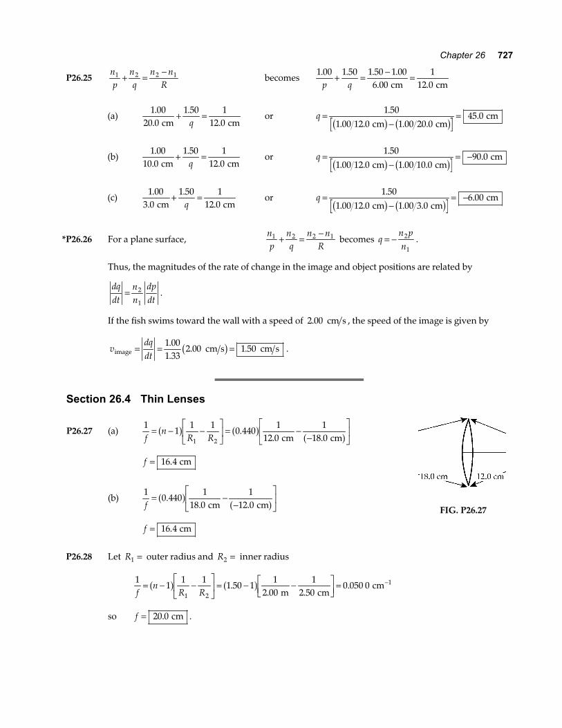
P26.27 (a) 1
11 1
0 4401
12 01
18 01 2fn
R R= − −
LNM
OQP
= −−
LNM
OQP
a f a f a f.. . cm cm
f = 16 4. cm
(b) 1
0 4401
18 01
12 0f= −
−LNM
OQP
.. .
a f a f cm cm
f = 16 4. cm
FIG. P26.27
P26.28 Let R1 = outer radius and R2 = inner radius
1
11 1
1 50 11
2 001
2 500 050 0
1 2
1
fn
R R= − −
LNM
OQP
= − −LNM
OQP =
−a f a f.. .
. m cm
cm
so f = 20 0. cm .
728 Image Formation by Mirrors and Lenses
P26.29 (a) 1 1 1 1
25 01
26 0q f p= − = −
. . cm cm q = 650 cm
The image is real, inverted, and enlarged .
(b) 1 1 1 1
25 01
24 0q f p= − = −
. . cm cm q = −600 cm
The image is virtual, upright, and enlarged .
P26.30 For a converging lens, f is positive. We use 1 1 1p q f
+ = .
(a) 1 1 1 1
20 01
40 01
40 0q f p= − = − =
. . . cm cm cm q = 40 0. cm
Mqp
= − = − = −40 040 0
1 00..
.
The image is real, inverted , and located 40.0 cm past the lens.
(b) 1 1 1 1
20 01
20 00
q f p= − = − =
. . cm cm q = infinity
No image is formed. The rays emerging from the lens are parallel to each other.
(c) 1 1 1 1
20 01
10 01
20 0q f p= − = − = −
. . . cm cm cm q = −20 0. cm
Mqp
= − = −−
=20 0
10 02 00
..
.a f
The image is upright, virtual and 20.0 cm in front of the lens.
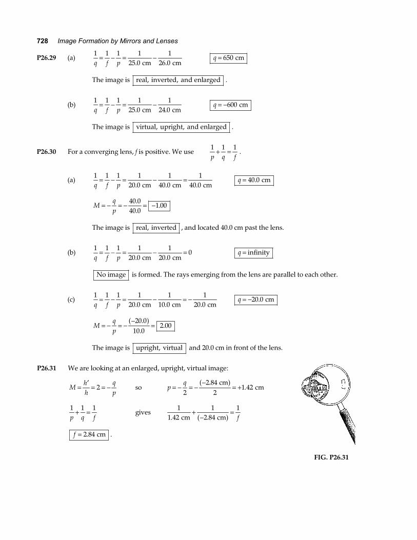
P26.31 We are looking at an enlarged, upright, virtual image:
Mhh
qp
= ′ = = −2 so pq
= − = −−
= +2
2 842
1 42.
. cm
cma f
1 1 1p q f
+ = gives 1
1 421
2 841
. . cm cm+
−=a f f
f = 2 84. cm .
FIG. P26.31
Chapter 26 729
P26.32 (a) 1 1 1p q f
+ = : 1
32 01
8 001
. . cm cm+ =
f
so f = 6 40. cm
(b) Mqp
= − = − = −8 000 250
..
cm32.0 cm
(c) Since f > 0 , the lens is converging .
P26.33 1 1 1p q f
+ = : p q− −+ =1 1 constant
We may differentiate through with respect to p: − − =− −1 1 02 2p qdqdp
dqdp
qp
M= − = −2
22 .
P26.34 The image is inverted: Mhh
qp
= ′ = − = − =−1 80
75 0.
. m
0.024 0 m q p= 75 0. .
(b) q p p p+ = = +3 00 75 0. . m p = 39 5. mm
(a) q = 2 96. m 1 1 1 1
0 039 51
2 96f p q= + = +
. . m m f = 39 0. mm
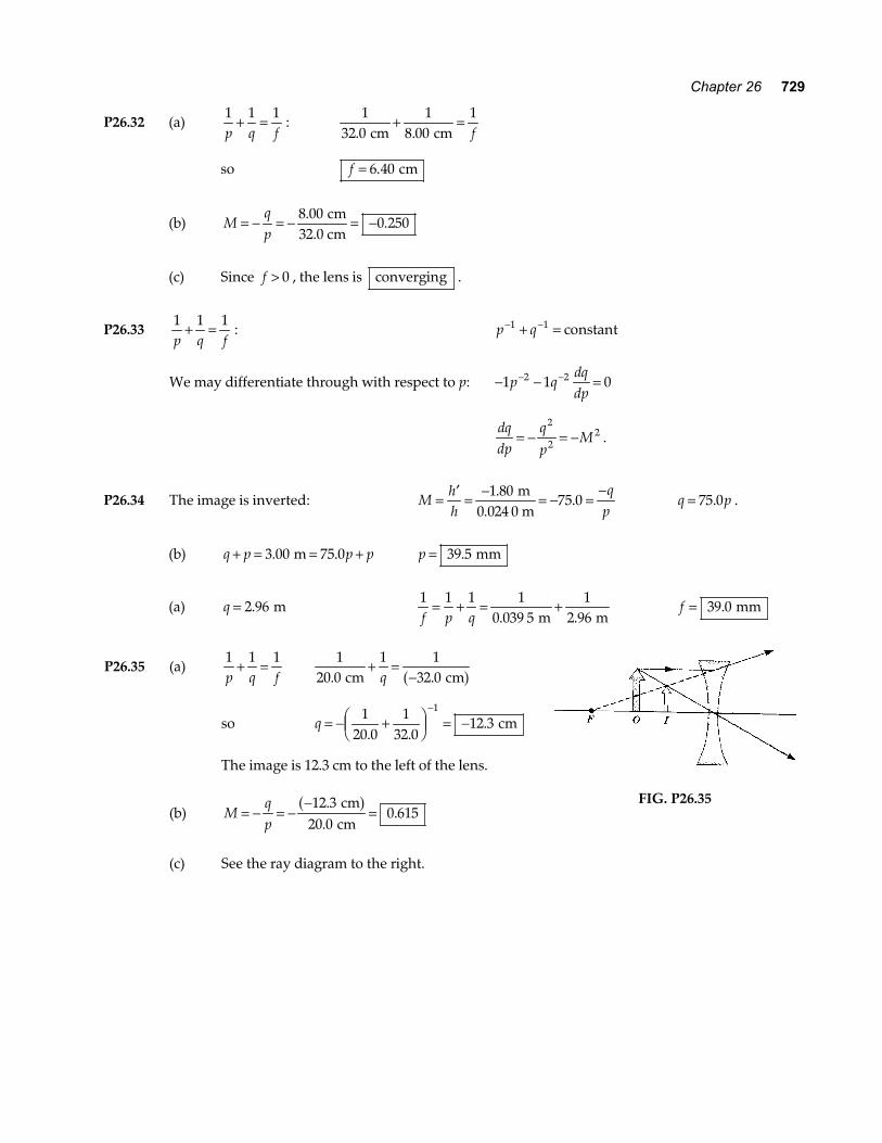
P26.35 (a) 1 1 1p q f
+ = 1
20 01 1
32 0. . cm cm+ =
−q a f
so q = − +FHG
IKJ = −
−120 0
132 0
12 31
. .. cm
The image is 12.3 cm to the left of the lens.
(b) Mqp
= − = −−
=12 3
20 00 615
..
. cm
cma f
(c) See the ray diagram to the right.
FIG. P26.35
730 Image Formation by Mirrors and Lenses
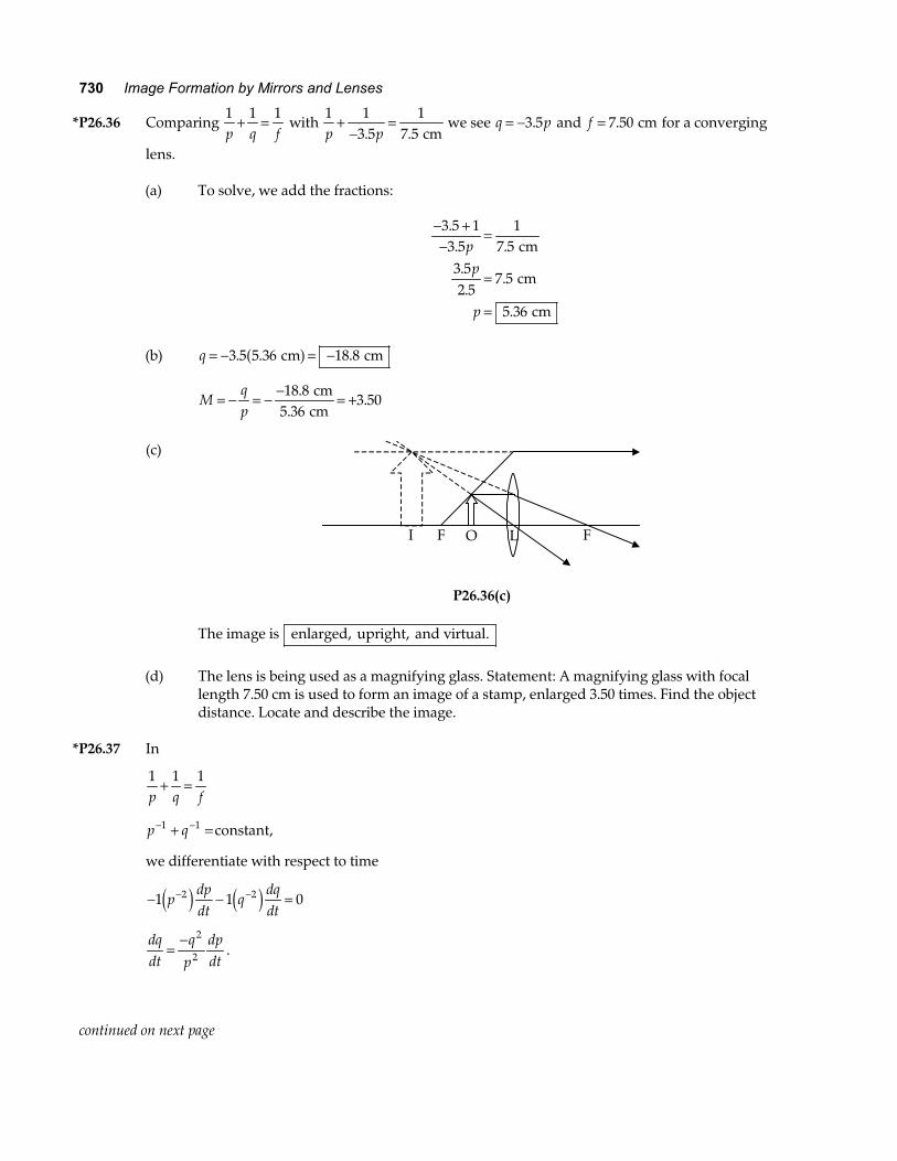
*P26.36 Comparing 1 1 1p q f
+ = with 1 1
3 51
7 5p p+
−=
. . cm we see q p= −3 5. and f = 7 50. cm for a converging
lens. (a) To solve, we add the fractions:
− +−
=
=
=
3 5 13 5
17 5
3 52 5
7 5
5 36
.. ...
.
.
pp
p
cm
cm
cm
(b) q = − = −3 5 5 36 18 8. . . cm cma f
Mqp
= − = − − = +18 85 36
3 50.
..
cm cm
(c)
I F O L F
P26.36(c) The image is enlarged, upright, and virtual.
(d) The lens is being used as a magnifying glass. Statement: A magnifying glass with focal
length 7.50 cm is used to form an image of a stamp, enlarged 3.50 times. Find the object distance. Locate and describe the image.
*P26.37 In
1 1 1p q f
+ =
p q− −+ =1 1 constant,
we differentiate with respect to time
− − =− −1 1 02 2pdpdt
qdqdte j e j
dqdt
qp
dpdt
=− 2
2 .
continued on next page
Chapter 26 731
We must find the momentary image location q:
1
201 1
0 3 m m+ =
q .
q = 0 305. m.
Now dqdt
= − = − =0 305
205 0 001 16 1 16
2
2
.. .
m
m m s m s mm s toward the lens
a fa f .
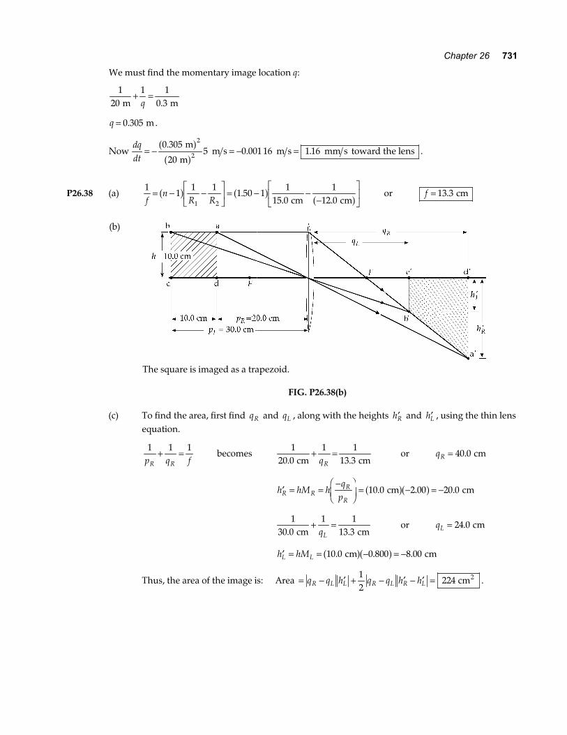
P26.38 (a) 1
11 1
1 50 11
15 01
12 01 2fn
R R= − −
LNM
OQP
= − −−
LNM
OQP
a f a f a f.. . cm cm
or f = 13 3. cm
(b)
The square is imaged as a trapezoid.
FIG. P26.38(b)
(c) To find the area, first find qR and qL , along with the heights ′hR and ′hL , using the thin lens
equation.
1 1 1
p q fR R+ = becomes
120 0
1 113 3. . cm cm
+ =qR
or qR = 40 0. cm
′ = =−FHGIKJ = − = −h hM h
qpR R
R
R10 0 2 00 20 0. . . cm cma fa f
1
30 01 1
13 3. . cm cm+ =
qL or qL = 24 0. cm
′ = = − = −h hML L 10 0 0 800 8 00. . . cm cma fa f
Thus, the area of the image is: Area = − ′ + − ′ − ′ =q q h q q h hR L L R L R L12
224 cm2 .
732 Image Formation by Mirrors and Lenses
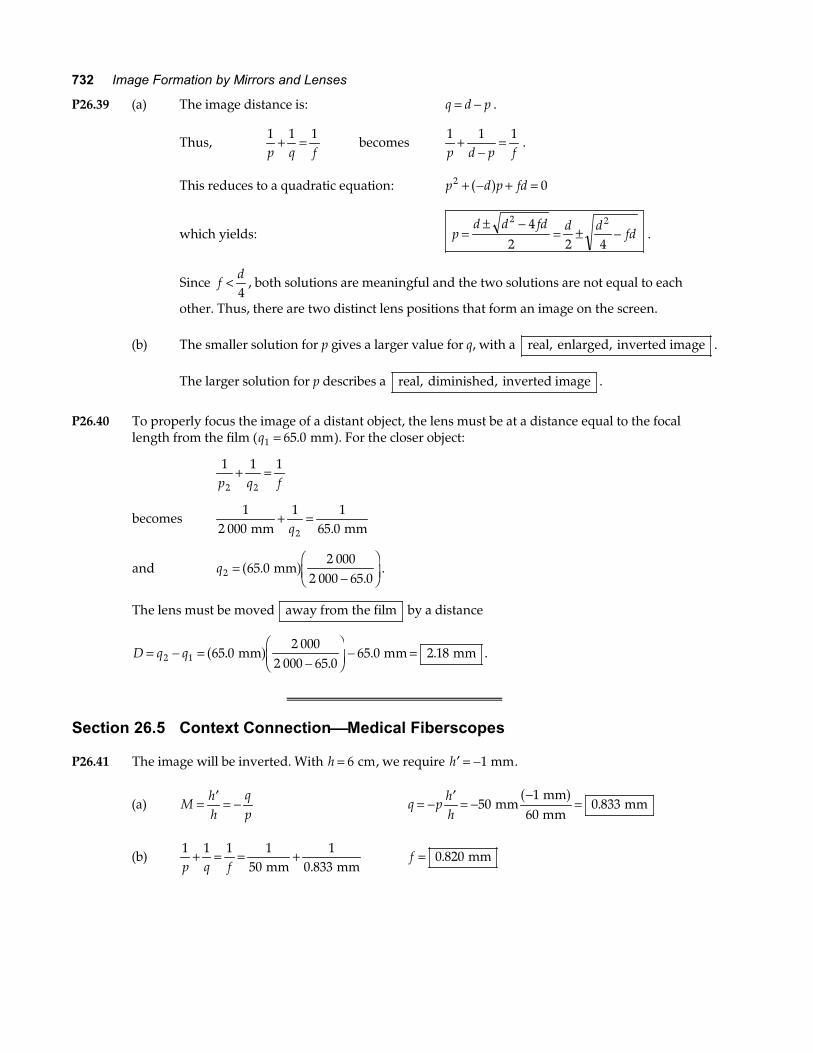
P26.39 (a) The image distance is: q d p= − .
Thus, 1 1 1p q f
+ = becomes 1 1 1p d p f
+−
= .
This reduces to a quadratic equation: p d p fd2 0+ − + =a f
which yields: pd d fd d d
fd=± −
= ± −2 242 2 4
.
Since fd<4
, both solutions are meaningful and the two solutions are not equal to each
other. Thus, there are two distinct lens positions that form an image on the screen. (b) The smaller solution for p gives a larger value for q, with a real, enlarged, inverted image .
The larger solution for p describes a real, diminished, inverted image .
P26.40 To properly focus the image of a distant object, the lens must be at a distance equal to the focal
length from the film (q1 65 0= . mm). For the closer object:
1 1 1
2 2p q f+ =
becomes 1
2 0001 1
65 02 mm mm+ =
q .
and q2 65 02 000
2 000 65 0=
−FHG
IKJ.
. mma f .
The lens must be moved away from the film by a distance
D q q= − =−
FHG
IKJ − =2 1 65 0
2 0002 000 65 0
65 0 2 18..
. . mm mm mma f .
Section 26.5 Context ConnectionMedical Fiberscopes P26.41 The image will be inverted. With h = 6 cm, we require ′ = −h 1 mm.
(a) Mhh
qp
= ′ = − q phh
= − ′ = −−
=501
600 833 mm
mmmm
mma f
.
(b) 1 1 1 1
501
0 833p q f+ = = +
mm mm. f = 0 820. mm
Chapter 26 733
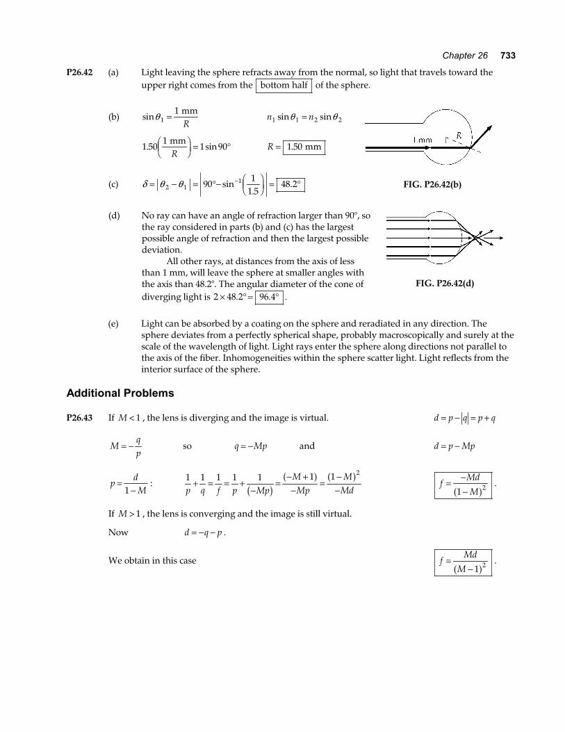
P26.42 (a) Light leaving the sphere refracts away from the normal, so light that travels toward the upper right comes from the bottom half of the sphere.
(b) sinθ 11= mm
R n n1 1 2 2sin sinθ θ=
1 501
1 90. sin mmRFHGIKJ = ° R = 1 50. mm
(c) δ θ θ= − = °− FHGIKJ = °−
2 1190
11 5
48 2sin.
.
FIG. P26.42(b)
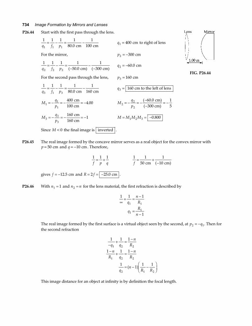
(d) No ray can have an angle of refraction larger than 90°, so
the ray considered in parts (b) and (c) has the largest possible angle of refraction and then the largest possible deviation.
All other rays, at distances from the axis of less than 1 mm, will leave the sphere at smaller angles with the axis than 48.2°. The angular diameter of the cone of diverging light is 2 48 2 96 4× ° = °. . .
FIG. P26.42(d)
(e) Light can be absorbed by a coating on the sphere and reradiated in any direction. The
sphere deviates from a perfectly spherical shape, probably macroscopically and surely at the scale of the wavelength of light. Light rays enter the sphere along directions not parallel to the axis of the fiber. Inhomogeneities within the sphere scatter light. Light reflects from the interior surface of the sphere.
Additional Problems P26.43 If M < 1 , the lens is diverging and the image is virtual. d p q p q= − = +
Mqp
= − so q Mp= − and d p Mp= −
pdM
=−1
: 1 1 1 1 1 1 1 2
p q f p MpMMp
MMd
+ = = +−
=− +−
=−−b g
a f a f f
Md
M= −
−1 2a f .
If M > 1 , the lens is converging and the image is still virtual.
Now d q p= − − .
We obtain in this case fMd
M=
− 1 2a f .
734 Image Formation by Mirrors and Lenses
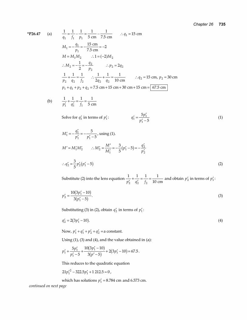
P26.44 Start with the first pass through the lens.
1 1 1 1
80 01
1001 1 1q f p= − = −
. cm cm q1 400= cm to right of lens
For the mirror, p2 300= − cm
1 1 1 1
50 01
3002 2 2q f p= − =
−−
−( . ( cm) cm) q2 60 0= − . cm
For the second pass through the lens, p3 160= cm
1 1 1 1
80 01
1603 1 3q f p= − = −
. cm cm q3 160= cm to the left of lens
Mqp1
1
1
4004 00= − = − = − cm
100 cm. M
qp2
2
2
60 0 15
= − = −−−
= −( .(
cm)300 cm)
Mqp3
3
3
1601= − = − = − cm
160 cm M M M M= = −1 2 3 0 800.
Since M <0 the final image is inverted .
FIG. P26.44
P26.45 The real image formed by the concave mirror serves as a real object for the convex mirror with
p = 50 cm and q = −10 cm. Therefore,
1 1 1f p q
= + 1 1
501
10f= +
− cm cma f gives f = −12 5. cm and R f= = −2 25 0. cm .
P26.46 With n1 1= and n n2 = for the lens material, the first refraction is described by
1 1 1
1
1 1
11
∞+ = −
=−
qnR
qR
n
The real image formed by the first surface is a virtual object seen by the second, at p q2 1= − . Then for
the second refraction
1 1 1
1 1 1
11
1 1
1 2 2
1 2 2
2 1 2
−+ = −
− + = −
= − −FHG
IKJ
q qn
Rn
R qn
R
qn
R Ra f
This image distance for an object at infinity is by definition the focal length.
Chapter 26 735
*P26.47 (a) 1 1 1 1
51
7 515
1 1 11q f p
q= − = − ∴ = cm cm
cm.
Mqp
M M M M
Mqp
p q
p q f q qq p
p q p q
11
1
1 2 2
22
22 2
2 2 2 2 22 2
1 2 2
152
1 2
12
2
1 1 1 12
1 110
15 30
7 5 15 30 15 67 5
= − = − = −
= ∴ = −
∴ = − = − ∴ =
+ = ∴ + = ∴ = =
+ + + = + + + =
cm7.5 cm
cm cm, cm
cm cm cm cm cm1
a f
. .
(b) 1 1 1 1
51 1 1′+
′= =
p q f cm
Solve for ′q1 in terms of ′p1 : ′ =′
′ −q
pp1
1
1
55
(1)
′ = −′′
= −′ −
Mqp p1
1
1 1
55
, using (1).
′ = ′ ′ ∴ ′ = ′′
= − ′ − = −′′
M M M MMM
pqp1 2 2
11
2
2
35
5b g
∴ ′ = ′ ′ −q p p2 2 135
5b g (2)
Substitute (2) into the lens equation 1 1 1 1
102 2 2′+
′= =
p q f cm and obtain ′p2 in terms of ′p1 :
′ =′ −
′ −p
p
p21
1
10 3 10
3 5b gb g . (3)
Substituting (3) in (2), obtain ′q2 in terms of ′p1 : ′ = ′ −q p2 12 3 10b g. (4) Now, ′ + ′ + ′ + ′ =p q p q1 1 2 2 a constant.
Using (1), (3) and (4), and the value obtained in (a):
′ +′
′ −+
′ −′ −
+ ′ − =pp
p
p
pp1
1
1
11
55
10 3 10
3 52 3 10 67 5
b gb g b g . .
This reduces to the quadratic equation
21 322 5 1 212 5 012
1′ − ′ + =p p. . ,
which has solutions ′ =p1 8 784. cm and 6.573 cm. continued on next page
736 Image Formation by Mirrors and Lenses
Case 1: ′ =p1 8 784. cm
∴ ′ − = − =p p1 1 8 784 7 5 1 28. . .cm cm cm.
From (4): ′ =q2 32 7. cm
∴ ′ − = − =q q2 2 32 7 15 17 7. .cm cm cm.
Case 2: ′ =p1 6 573. cm
∴ ′ − = − = −p p1 1 6 573 7 5 0 927. . .cm cm cm .
From (4): ′ =q2 19 44. cm
∴ ′ = = − =q q2 2 19 44 15 4 44. .cm cm cm.
From these results it is concluded that:
The lenses can be displaced in two ways. The first lens can be moved 1.28 cm farther fromthe object and the second lens 17.7 cm toward the object. Alternatively, the first lens canbe moved 0.927 cm toward the object and the second lens 4.44 cm toward the object.
P26.48 1 1 1 1
10 01
12 51 1 1q f p= − = −
. . cm cm
so q1 50 0= . cm (to left of mirror).
This serves as an object for the lens (a virtual object), so
1 1 1 1
16 71
25 02 2 2q f p= − =
−−
−. . cm cma f a f and q2 50 3= − . cm,
meaning 50.3 cm to the right of the lens. Thus, the final image is located 25 3. cm to right of mirror .
Mqp
Mqp
M M M
11
1
22
2
1 2
50 04 00
50 325 0
2 01
8 05
= − = − = −
= − = −−−
= −
= =
..
.
..
.
cm12.5 cm
cm cm
a fa f
Thus, the final image is virtual, upright , 8.05 times the size of object, and 25.3 cm to right of the
mirror.
Chapter 26 737
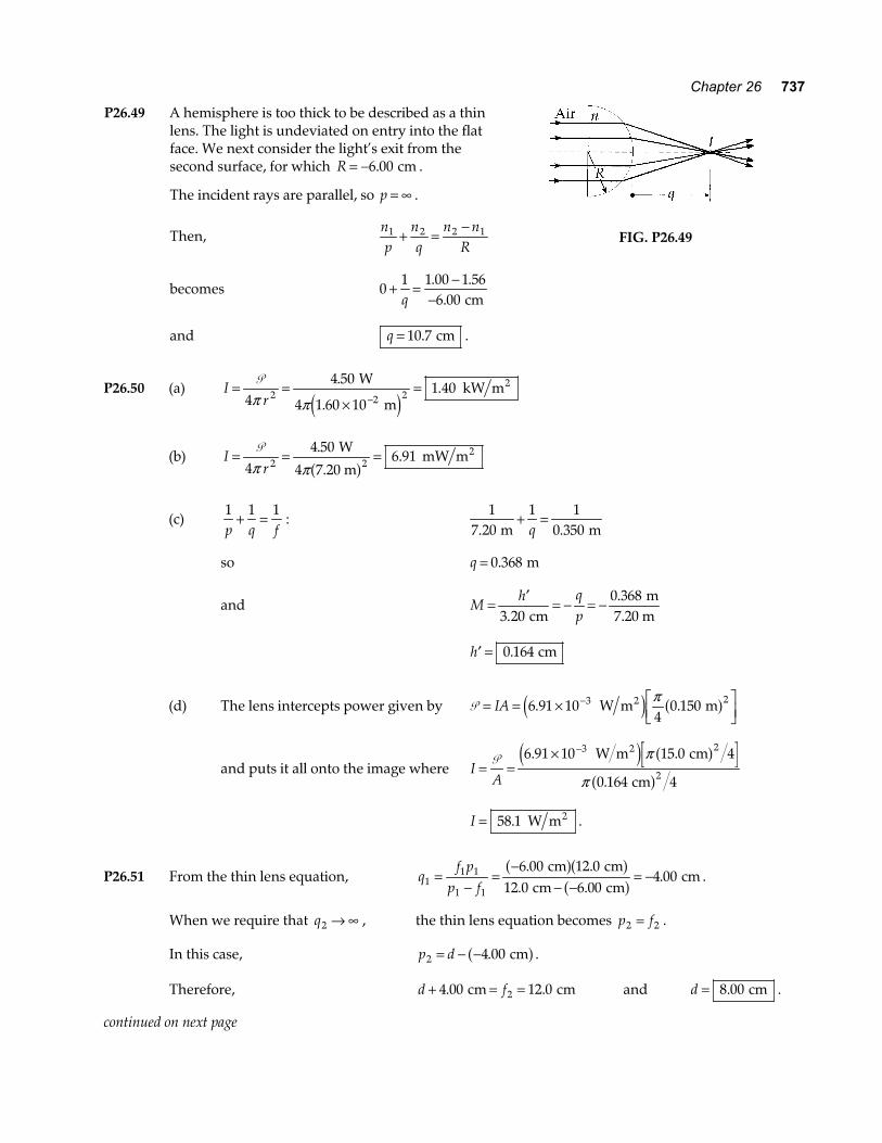
P26.49 A hemisphere is too thick to be described as a thin lens. The light is undeviated on entry into the flat face. We next consider the light’s exit from the second surface, for which R = −6 00. cm .
The incident rays are parallel, so p = ∞ .
Then, np
nq
n nR
1 2 2 1+ =−
becomes 01 1 00 1 56
6 00+ = −
−q. .
. cm
and q = 10 7. cm .
FIG. P26.49
P26.50 (a) Ir
= =×
=−
P4
4 50
4 1 60 101 402 2 2π π
.
..
W
m kW m2
e j
(b) Ir
= = =P4
4 506 912 2π π
..
W
4 7.20 m mW m2
a f
(c) 1 1 1p q f
+ = : 1
7 201 1
0 350. . m m+ =
q
so q = 0 368. m
and Mh q
p= ′ = − = −
3 200 368
..
cm m
7.20 m
′ =h 0 164. cm
(d) The lens intercepts power given by P = = × LNM
OQP
−IA 6 91 104
0 1503 2. . W m m2e j a fπ
and puts it all onto the image where IA
= =× −
P 6 91 10 15 0 4
0 164 4
3 2
2
. .
.
W m cm
cm
2e j a fa f
π
π
I = 58 1. W m2 .
P26.51 From the thin lens equation, qf p
p f11 1
1 1
6 00 12 012 0 6 00
4 00=−
=−
− −= −
. .. .
. cm cm
cm cm cm
a fa fa f .
When we require that q2 → ∞ , the thin lens equation becomes p f2 2= .
In this case, p d2 4 00= − − . cma f .
Therefore, d f+ = =4 00 12 02. . cm cm and d = 8 00. cm .
continued on next page
738 Image Formation by Mirrors and Lenses
FIG. P26.51
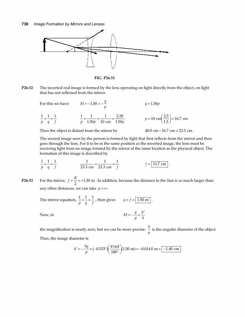
P26.52 The inverted real image is formed by the lens operating on light directly from the object, on light
that has not reflected from the mirror.
For this we have Mqp
= − = −1 50. q p= 1 50.
1 1 1p q f
+ = 1 1
1 501
102 50
1 50p p p+ = =
..
. cm p = F
HGIKJ =10
2 51 5
16 7 cm cm..
.
Then the object is distant from the mirror by 40 0 16 7 23 3. . .cm cm cm− = .
The second image seen by the person is formed by light that first reflects from the mirror and then goes through the lens. For it to be in the same position as the inverted image, the lens must be receiving light from an image formed by the mirror at the same location as the physical object. The formation of this image is described by
1 1 1p q f
+ = 1
23 31
23 31
. . cm cm+ =
f f = 11 7. cm .
P26.53 For the mirror, fR= = +2
1 50. m . In addition, because the distance to the Sun is so much larger than
any other distances, we can take p = ∞ .
The mirror equation, 1 1 1p q f
+ = , then gives q f= = 1 50. m .
Now, in Mqp
hh
= − = ′
the magnification is nearly zero, but we can be more precise: hp
is the angular diameter of the object.
Thus, the image diameter is
′ = − = − °°
FHGIKJ = − = −h
hqp
0 533 1 50 0 014 0 1 40. . . .a f a fπ rad180
m m cm .
Chapter 26 739
P26.54 (a) For the light the mirror intercepts,
P = =I A I Ra0 02π
350 1 000 2 W W m2= e jπ Ra
and Ra = 0 334. m or larger .
(b) In 1 1 1 2p q f R
+ = =
we have p → ∞
so qR=2
Mhh
qp
= ′ = −
so ′ = −FHGIKJ = −FHG
IKJ °
°FHGIKJ
LNM
OQP = −FHG
IKJh q
hp
R R2
0 5332
9 30. .π rad180
m rada f
where hp
is the angle the Sun subtends. The intensity at the image is
then Ih
I Rh
I R
R
a a=′
=′
=× −
Pπ
ππ2
02
20
2
2 3 244 4
2 9 30 10b g e j. rad
120 1016 1 000
9 30 10
32
2 3 2× =× −
W m W m
rad
22e j
e jR
R
a
.
so RR
a = 0 025 5. or larger .
P26.55 In the original situation, p q1 1 1 50+ = . m .
In the final situation, p p2 1 0 900= + . m
and q q p2 1 10 900 0 600= − = −. .m m .
Our lens equation is 1 1 1 1 1
1 1 2 2p q f p q+ = = + .
Substituting, we have 1 1
1 5010 900
10 6001 1 1 1p p p p
+−
=+
+−. . . m
.
Adding the fractions, 1 50
1 500 600 0 900
0 900 0 6001 1
1 1
1 1
1 1
..
. .. .
m m− +
−=
− + ++ −
p pp p
p pp pb g b gb g .
Simplified, this becomes p p p p1 1 1 11 50 0 900 0 600. . . m − = + −b g b gb g .
FIG. P26.55
continued on next page
740 Image Formation by Mirrors and Lenses
(a) Thus, p10 5401 80
0 300= =..
. m m p p2 1 0 900 1 20= + =. . m
(b) 1 1
0 3001
1 50 0 300f= +
−. . . m m m and f = 0 240. m
(c) The second image is real, inverted, and diminished
with Mqp
= − = −2
20 250. .
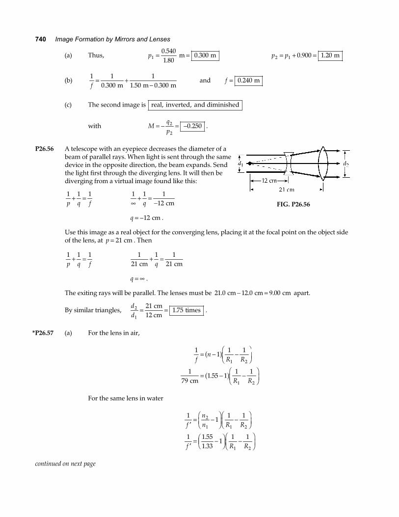
P26.56 A telescope with an eyepiece decreases the diameter of a
beam of parallel rays. When light is sent through the same device in the opposite direction, the beam expands. Send the light first through the diverging lens. It will then be diverging from a virtual image found like this:
1 1 1p q f
+ = 1 1 1
12∞+ =
−q cm
q = −12 cm .
FIG. P26.56
Use this image as a real object for the converging lens, placing it at the focal point on the object side of the lens, at p = 21 cm . Then
1 1 1p q f
+ = 1
211 1
21 cm cm+ =
q
q = ∞ .
The exiting rays will be parallel. The lenses must be 21 0 12 0 9 00. . .cm cm cm− = apart.
By similar triangles, dd
2
1
211 75= = cm
12 cm times. .
*P26.57 (a) For the lens in air,
11
1 1
179
1 55 11 1
1 2
1 2
fn
R R
R R
= − −FHG
IKJ
= − −FHG
IKJ
a f
a f cm
.
For the same lens in water
11
1 1
1 1 551 33
11 1
2
1 1 2
1 2
′= −FHGIKJ −FHG
IKJ
′= −FHG
IKJ −FHG
IKJ
fnn R R
f R R..
continued on next page
Chapter 26 741
By division,
179
10 550 165 79
79 3 32 263
cm
cm
cm cm
′= =
′
′ = =
f
f
f
..
.a f
(b) The path of a reflected ray does not depend on the refractive index of the medium which
the reflecting surface bounds. Therefore the focal length of a mirror does not change when it
is put into a different medium: ′ = = =fR
f2
79 0. cm .
P26.58 (a) The lens makers’ equation, 1
11 1
1 2fn
R R= − +
FHG
IKJa f
becomes: 1
5 001
19 00
111 0. . . cm cm cm
= − −−
LNM
OQP
na f a f giving n = 1 99. .
(b) As the light passes through the lens for the first time, the thin lens equation
1 1 1
1 1p q f+ =
becomes: 1
8 001 1
5 001. . cm cm+ =
q
or q1 13 3= . cm , and Mqp1
1
1
13 31 67= − = − = −..
cm8.00 cm
.
This image becomes the object for the concave mirror with:
p qm = − = − =20 0 20 0 13 3 6 671. . . . cm cm cm cm
and fR= = +2
4 00. cm .
The mirror equation becomes: 1
6 671 1
4 00. . cm cm+ =
qm
giving qm = 10 0. cm
and Mqp
m
m2
10 01 50= − = − = −..
cm6.67 cm
.
The image formed by the mirror serves as a real object for the lens on the second pass of the light through the lens with:
p qm3 20 0 10 0= − = +. . cm cm .
The thin lens equation yields: 1
10 01 1
5 003. . cm cm+ =
q
continued on next page
742 Image Formation by Mirrors and Lenses
or q3 10 0= . cm
and Mqp3
3
3
10 01 00= − = − = −..
cm10.0 cm
.
The final image is a real image located 10 0. cm to the left of the lens .
The overall magnification is M M M Mtotal = = −1 2 3 2 50. .
(c) Since the total magnification is negative, this final image is inverted .
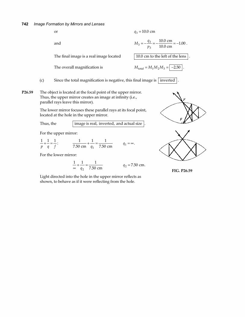
P26.59 The object is located at the focal point of the upper mirror.
Thus, the upper mirror creates an image at infinity (i.e., parallel rays leave this mirror).
The lower mirror focuses these parallel rays at its focal point, located at the hole in the upper mirror.
Thus, the image is real, inverted, and actual size .
For the upper mirror:
1 1 1p q f
+ = : 1
7 501 1
7 501. . cm cm+ =
q q1 = ∞ .
For the lower mirror:
1 1 1
7 502∞+ =
q . cm q2 7 50= . cm.
Light directed into the hole in the upper mirror reflects as shown, to behave as if it were reflecting from the hole.
FIG. P26.59
Chapter 26 743
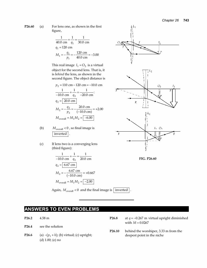
P26.60 (a) For lens one, as shown in the first figure,
140 0
1 130 0
120120
3 00
1
1
11
1
. .
.
cm cm cm
cm40.0 cm
+ =
=
= − = − = −
qq
Mqp
This real image I O1 2= is a virtual object for the second lens. That is, it is behind the lens, as shown in the second figure. The object distance is
p
q
q
Mqp
M M M
2
2
2
22
2
1 2
110 120 10 01
10 01 1
20 0
20 0
20 02 00
6 00
= − = −
−+ =
−
=
= − = −−
= +
= = −
cm cm cm
cm cm
cm
cm10.0 cm
overall
.
. .:
.
..
.
a f
(b) Moverall < 0 , so final image is
inverted .
(c) If lens two is a converging lens
(third figure):
110 0
1 120 0
6 67
6 6710 0
0 667
2 00
2
2
2
1 2
−+ =
=
= −−
= +
= = −
. .
.
..
.
.
cm cm
cm
cm cm
overall
q
q
M
M M M
a f
FIG. P26.60
Again, Moverall < 0 and the final image is inverted .
ANSWERS TO EVEN PROBLEMS P26.2 4.58 m P26.4 see the solution P26.6 (a) − +p h1b g; (b) virtual; (c) upright; (d) 1.00; (e) no
P26.8 at q = −0 267. m virtual upright diminished with M = 0 0267.
P26.10 behind the worshiper, 3.33 m from the
deepest point in the niche
744 Image Formation by Mirrors and Lenses
P26.12 (a) 2.22 cm; (b) 10.0 P26.14 (a) 160 mm; (b) –267 mm P26.16 (a) convex; (b) at the 30.0 cm mark; (c) −20.0 cm P26.18 (a) 15.0 cm; (b) 60.0 cm P26.20 (a) see the solution; (b) at 0.639 s and 0.782 s P26.22 4.82 cm P26.24 see the solution, the image is real,
inverted, and diminished P26.26 1 50. cm s P26.28 20.0 cm P26.30 (a) q = 40 0. cm , M = −1 00. , real and
inverted; (b) q → ∞ , no image is formed; (c) q = −20 0. cm, M = +2 00. , virtual and
upright P26.32 (a) 6.40 cm; (b) –0.250; (c) converging P26.34 (a) f = 39 0. mm ; (b) p = 39 5. mm P26.36 (a) 5.36 cm; (b) −18.8 cm; (c) virtual, right side up, enlarged; (d) A magnifying glass with focal length
7.50 cm is used to form an image of a stamp, enlarged 3.50 times. Find the object distance. Locate and describe the image.
P26.38 (a) f = 13 3. cm; (b) see the solution; (c) 224 2 cm
P26.40 2.18 mm away from the film plane P26.42 (a) the bottom half; (b) 1.50 mm; (c) 48.2°;
(d) see the solution, 96.4°; (e) see the solution P26.44 160 cm to the left of the lens, inverted,
M = −0 800. P26.46 see the solution P26.48 25.3 cm to the right of the mirror, virtual,
upright, enlarged 8.05 times P26.50 (a) 1 40. kW m2 ; (b) 6 91. mW m2 ; (c) 0.164 cm; (d) 58 1. W m2 P26.52 11.7 cm P26.54 (a) 0.334 m or larger; (b) Ra must be at least 0.025 5 R P26.56 Align the lenses on the same axis and
9.00 cm apart. Let the light pass first through the diverging lens and then through the converging lens. The diameter increases by a factor of 1.75.
P26.58 (a) 1.99; (b) 10.0 cm to the left of the lens, –2.50; (c) inverted P26.60 (a) 20.0 cm to the right of the second
lens, −6.00; (b) inverted; (c) 6.67 to the right of the second lens,