IMAGE Failure Review Board Final Report Executive Summary September 19, 2006 Contact with the IMAGE spacecraft unexpectedly stopped on December 18, 2005 when failure to establish a routine communications contact with the Deep Space Network (DSN) occurred. Multiple attempts were made to reestablish communications, all of which have been unsuccessful. A Failure Review Board (FRB) was established on January 27, 2006 to investigate the cause of the failure, examine the operations actions taken in response to the failure, and identify lessons learned applicable to other NASA missions. The FRB completed its analysis and presented findings to Goddard Space Flight Center (GSFC) Flight Programs & Projects Directorate management on April 21, 2006. This report provides detailed information on the findings and conclusions of the FRB’s investigation. The FRB’s Final Presentation chart package provides essential supporting information to this report and is referenced throughout. Key Findings 1. It is likely IMAGE became unable to continue routine communications due to a Single Event Upset (SEU) induced ‘instant trip’ of the Solid State Power Controller (SSPC) supplying power to the Transponder. However, several other possible, but very unlikely, causes exist that cannot be completely eliminated. A recurrence of the anomaly is possible and cannot be prevented. 2. The previous anomaly history of IMAGE was not a harbinger of the current failure. However, the anomaly history of EO-1 and WMAP were, since three similar SSPC instant trip anomalies had been observed between the EO-1 and WMAP missions. 3. The operational response to the anomaly was timely, appropriate, and complete. 4. It is unlikely that the IMAGE mission can be revived. However, the October 2007 eclipse season may permit a Transponder SSPC reset (and a re-powering of the Transponder), but this is not certain given that the main bus reset level may really be 21 V. If revival occurs, the mission should be able to continue as before with no limitations. Although the anomaly may result in the end of the IMAGE mission, the FRB wishes to note that the IMAGE primary mission had been successfully completed and that the anomaly occurred well into its extended mission. The science gathered thus far has been significant in the understanding of magnetosphere dynamics and behavior and has resulted in 37 unique scientific discoveries. Root Cause Details The SSPC provides power service to the Transponder in addition to circuit breaker like functionality. Nominally, a trip of the device is reported in its status telemetry lines that are continuously monitored by onboard Failure Detection and Correction (FDC) logic. This allows the FDC to command the SSPC to close reapplying power to the Transponder. However, due to a design oversight in the device, instant trip events (those of high but short lived current transients) are not reported in the status telemetry lines, allowing the device to be in an open state while still reporting a closed state. The result is that the Transponder remains OFF due to the fact that the FDC logic detects the SSPC to still be closed (due to the erroneous status line
Transcript
IMAGE Failure Review Board Final Report Executive Summary
September 19, 2006
Contact with the IMAGE spacecraft unexpectedly stopped on December 18, 2005 when failure to establish a routine communications contact with the Deep Space Network (DSN) occurred. Multiple attempts were made to reestablish communications, all of which have been unsuccessful. A Failure Review Board (FRB) was established on January 27, 2006 to investigate the cause of the failure, examine the operations actions taken in response to the failure, and identify lessons learned applicable to other NASA missions. The FRB completed its analysis and presented findings to Goddard Space Flight Center (GSFC) Flight Programs & Projects Directorate management on April 21, 2006. This report provides detailed information on the findings and conclusions of the FRB’s investigation. The FRB’s Final Presentation chart package provides essential supporting information to this report and is referenced throughout. Key Findings
1. It is likely IMAGE became unable to continue routine communications due to a Single Event Upset (SEU) induced ‘instant trip’ of the Solid State Power Controller (SSPC) supplying power to the Transponder. However, several other possible, but very unlikely, causes exist that cannot be completely eliminated. A recurrence of the anomaly is possible and cannot be prevented.
2. The previous anomaly history of IMAGE was not a harbinger of the current failure. However, the anomaly history of EO-1 and WMAP were, since three similar SSPC instant trip anomalies had been observed between the EO-1 and WMAP missions.
3. The operational response to the anomaly was timely, appropriate, and complete. 4. It is unlikely that the IMAGE mission can be revived. However, the October 2007
eclipse season may permit a Transponder SSPC reset (and a re-powering of the Transponder), but this is not certain given that the main bus reset level may really be 21 V. If revival occurs, the mission should be able to continue as before with no limitations.
Although the anomaly may result in the end of the IMAGE mission, the FRB wishes to note that the IMAGE primary mission had been successfully completed and that the anomaly occurred well into its extended mission. The science gathered thus far has been significant in the understanding of magnetosphere dynamics and behavior and has resulted in 37 unique scientific discoveries.
Root Cause Details The SSPC provides power service to the Transponder in addition to circuit breaker like functionality. Nominally, a trip of the device is reported in its status telemetry lines that are continuously monitored by onboard Failure Detection and Correction (FDC) logic. This allows the FDC to command the SSPC to close reapplying power to the Transponder. However, due to a design oversight in the device, instant trip events (those of high but short lived current transients) are not reported in the status telemetry lines, allowing the device to be in an open state while still reporting a closed state. The result is that the Transponder remains OFF due to the fact that the FDC logic detects the SSPC to still be closed (due to the erroneous status line
IMAGE FRB Final Report
September 19, 2006
2
indication). The SSPC’s erroneous reporting of instant trip events was not known at the time the IMAGE mission was under development. Lessons Learned Lesson #1: The Transponder Receiver should have redundancy built into its power switching or the sensed operational status – even if the mission is designed as single string throughout. Lesson #2: The Part anomaly alert process should be more inclusive to operations personnel. If it could include alerts to missions that are using the part, then some preventive operational mitigations might be put into effect. Lesson #3: Complete and accurate as-built design documentation is essential for anomaly resolution. As-built documentation should include a searchable parts list. Lesson #4: Safing limits & operational procedures related to Battery State of Charge (SOC) should be adjusted to account for battery degradation as the mission progresses past the nominal lifetime.
IMAGE FRB Final Report
September 19, 2006
3
Contents Page
Executive Summary 1 1. FRB Charter and Membership 4 2. Summary of Lost Contact & Response 5 3. Anomaly History 7 4. Fault Analysis 9 5. Mission Recovery Possibilities 14 6. Lessons Learned 19 7. Conclusions 22
1. FRB Charter and Membership The GSFC Flight Programs & Projects Directorate management tasked the IMAGE FRB to assess the following areas in its investigation:
1. Review previous IMAGE spacecraft anomalies and history to identify possible relevance to the failure event.
2. Assess the spacecraft operation prior to and during the event. Review spacecraft engineering data trends leading up to the event.
3. Review the adequacy of the recovery operations used in response to the event. Identify any additional procedures or tests that should be executed.
4. Perform a fault tree analysis and identify the likely cause(s) of the failure. Identify possible impacts to other missions that may be susceptible to similar failures.
5. Identify the documentation and data that should be captured to closeout the IMAGE operation.
The IMAGE FRB membership was selected to include individuals with expertise in spacecraft subsystem design, flight operations, parts, quality assurance and reliability, space environment and radiation. Additional members were added as consultants to provide expertise in other areas as needed. The Air Force’s AMOS1 facility and staff were utilized to provide on-orbit spacecraft thermal and body spin rate measurements (discussed more in Fault Analysis Section).
Mike Prior / FRB Chairman Code 441, Goddard Space Flight Center
Main Board Consultants
Name Title/Org Name Title/Org Lou Barbieri Secretary/444 Greg Dirks Thermal/SwRI Pat Crouse SSMO Project Manager/444 Dave Somes RF/L3 Comm Jim La SSMO Engineer/568 Mali Hakimi Space weather/444 Rick Burley IMAGE Mission Director/612.4 Dr Gopalakrishn Rao Power/563 Steve Coyle MAP Mission Director /581 John Armantrout Power/LMMS Amri Hernandez-Pellerano
Power/563 Roger Hollandsworth Power/LMMS
Mike Powers RF Communications/567 Jim Riker AMOS/Air Force Jon Verville Ground System RF/567 Paul Kervin AMOS/Air Force Scott Hull Parts, Orbital Debris/592 James Surachi Quality Assurance/300.1 Dan Butler Thermal/545 Michael Choi Thermal/545 Mark Tapley Systems Engineering/SwRI Gerry Grismore C&DH, Electrical/LMMS Ray Ladbury Radiation/561.4
1 Air Force Maui Optical Station, the Air Force’s Maui optical and supercomputing site.
IMAGE FRB Final Report
September 19, 2006
5
2. Summary of Lost Contact & Response Sometime between 0739 UTC and 15152 UTC on December 18, 2005 normal downlink transmission from the IMAGE spacecraft became undetectable by NASA Deep Space Network (DSN) stations. Multiple attempts were made to reestablish communications utilizing the full suite of DSN capabilities and external (non-DSN) ground station resources. Attempts were made at commanding the transmitter ON as well as rebooting the spacecraft’s main computer that were unsuccessful. IMAGE also did not respond to commands to re-establish a downlink that included reconfiguring the RF system, switching between antennas, switching data rates and resetting the Power Distribution Unit. Downlink receiver frequencies were swept and uplink power increased from 1 Kw to 10 Kw . Multiple DSN stations showed the same negative results as well as the Berkeley Ground Station (an external tracking station operated by the University of California at Berkeley that had been previously used to track IMAGE). The IMAGE flight team had declared a state of emergency promptly after the first missed contact in order to secure additional resources for the troubleshooting activities described above. USSTRATCOM3 was contacted to perform radar sweeps in order to detect debris from a possible collision or explosion as well as to perform an independent orbit determination from skin track data for comparison with Two Line Elements (TLEs) from JPL. Results indicated no debris in the immediate vicinity of IMAGE. Additionally, TLE comparisons indicated a match with JPL thus implying no change in the orbit that might occur as a result of a large impact. Telemetry leading up to the lost contact indicated nominal healthy operation of all subsystems. No trends had existed indicating imminent failure of any subsystem or component. No atypical commanding, either during the previous DSN pass or through the onboard command load had been performed4. Table 2-1 summarizes the specific events (including commanding) that took place from the time of the last successful DSN contact up to the time when communications contact was lost.
Table 2-1. Anomaly Event Summary Time
(Year/DOY UTC) Activity
2005/352 0714 All instruments to full science. 2005/352 0740 End of Good DSN pass @DS-34. 2005/352 0755 Configure RF for low-rate via stored command. 2005/352 1125 IMAGE at apogee. 2005/352 1515 Configure RF to high-rate via stored command.
2 The last telemetry packet received by DSN occurred at 0739 UTC on 12/18 at the end of a DSN contact that started and ended nominally. The subsequent contact starting at 1515 UTC was unsuccessful with no telemetry or RF signal received. 3 United States Strategic Command. 4 Configure RF for Low-rate via stored command and Configure RF to high-rate via stored command were performed. These are typical commands that had been successfully performed hundreds of times on-orbit.
IMAGE FRB Final Report
September 19, 2006
6
Table 2-1. Anomaly Event Summary 2005/352 1620 No IMAGE RF signal @DS-34.
The IMAGE FRB was convened on January 27 to continue the anomaly investigation that had already been started by members of the IMAGE Flight Operations Team (FOT) and Space Science Mission Operations (SSMO) Project Management personnel. A summary of the anomaly response is shown in Table 2-2 below.
Table 2-2. Anomaly Response Summary 2005 12/18 The IMAGE Mission Director (MD) was contacted by DSN Operations Chief about
imminent pass failure at DS34 due to no RF signal. Support was switched from DS34 to DS44 in the event of an undiagnosed problem with DS34. Still no signal. MD scheduled an emergency pass at DS66 and alerted IMAGE team.
12/18 During DS66 pass commands were sent in the blind to IMAGE to turn the Transmitter on/off/on, to switch from MGA to LGA's, direct modulation on/off, subcarrier modulation off/on, coherent mode off/on, and ranging mode off/on. Still no signal. MD issued Anomaly report.
12/19 Continued attempts to contact IMAGE without success. PDU reset commands were sent. Trend data analysis did not suggest any cause. MD directed DSN to reload antenna pointing data. Verified antenna pointing with predicts and antenna Az/El reported in 0158 Monitor Blocks. MD, in consultation with other elements of IMAGE team decides to wait for 72 hour watchdog timer.
12/20 Berkeley Ground Station reports no RF signal from IMAGE. BGS had tracked IMAGE during part of its mission for R/T science data. Using BGS eliminated possibility of undiagnosed, systemic DSN problem.
12/21 72 hours from last known command to reach IMAGE. Still no RF signal. 12/22 72 hours from last attempted command to reach IMAGE. Still no RF signal, even on
DS43. USSTRATCOM Collision assessment reports no debris within 50km of IMAGE, and updated TLEs made with active radar match JPL’s, and suggest no impact-induced Delta-V.
12/23 Resume regular blind commanding in attempt to revive IMAGE with increasing uplink power.
2006 1/11 NORAD contacted for fault isolation testing support. MD requested that they observe
IMAGE optically to detect commanded changes in spin rate, thermal condition, and RPI aliveness. Not yet aware of AMOS capabilities for this type of support.
1/13 SSPC failure/recovery mode hypothesized. 1/18 Recovery plan forwarded to JPL to start planning. 1/26 SSPCCntl (Transponder) command uncommented from command database and sent
repeatedly without effect. 1/27 IMAGE FRB begins.
Upon examination of the anomaly response noted above, it is the conclusion of the FRB that appropriate and thorough actions were taken by the IMAGE FOT and Management in response to initial loss of contact. Appropriate resources were called into place and utilized as well as the exercise of available options that were readily available during subsequent follow-up actions.
IMAGE FRB Final Report
September 19, 2006
7
3. Anomaly History The FRB charter tasked the FRB to investigate the mission’s anomaly history to assess if any previous events could be seen as a precursor to the failure. The IMAGE Mission Director’s detailed log was examined as well as the GSFC SOARS (Spacecraft Orbital Anomaly Reporting System) system to produce a timeline of significant anomaly events over the life of the mission. The timeline (shown in Table 3-1) also lists other significant events during the mission to provide the reader with more perspective on the entire mission’s history.
Table 3-1. IMAGE Mission Significant Events Year/Date Event 2000/03/25 Launch nominal. IOC largely nominal, except for Nutation Damper, MMM
bug, Clockdrift. 2000/05/11 RPI deployment complete. Full instrument checkout begins. 2000/05/16 RPI Y-axis transmitter fails. 2000/06/10 AST 'Summer Vacation' condition first detected. 2000/06/12 RPI X-axis transmitter s/w 'fuse' uploaded. 2000/06/12 IMAGE handed from Code 410 to Code 444. 2000/06/17 CIDP TAS safes payload due to spin-rate oscillations. 2000/07/14 Bastille Day solar storm, MENA safes itself, LENA saturated. 2000/10/03 Loss of approximately 130m of RPI -X cause’s loss of spin balance. 2000/12/13 CIDP TAS patch 1 installed. 2001/01/11 CIDP reboot due to multiple uncorrectable bit errors during large CME. 2001/09/18 Lost approximately 25m of RPI +Y axis antenna. 2001/10/11 CIDP TAS safes payload due to sun-cross error due to extreme sun angle.
Start running CIDP with payload TAS-safing turned OFF. 2002/08/09 Lost RPI -Y tip mass and negligible length of wire. 2003/03/30 Begin 2003 Mega-Eclipse season. Eclipses in excess of IMAGE’s prime
mission design. Payload power-safed by S/C FDC macro's. 2003/04/08 SCU reboot due to S/C FDC power macros. Stored commands brought
heaters online too soon after eclipse exit. 2003/04/21 IMAGE back to nominal operations after Mega-Eclipse season. 2003/11/20 RS422 serial interface between MENA and CIDP hung up during major
(DST>400) solar storm. Failure to receive status messages from CIDP caused MENA to disable its High Voltage.
2004/01/22 RPI software latch up due to multiple SEUs on memory card. Verified no h/w damage by running built in diagnostics tests on EEPROM. Then reloaded flight software from verified EEPROM, and resumed nominal operations.
2004/09/30 Lost most/all of RPI +Y antenna. 2004/11/25 SCU warm reboot due to PDU FDC. SCU Power Supply switched from A
to B. 2005/02/01 SCU warm reboot. Cause undetermined. SCU Power Supply still on B
side. 2005/04/01 FUV begins GEO 'Spring Break' mode due to WIC degradation red-leak.
IMAGE FRB Final Report
September 19, 2006
8
Table 3-1. IMAGE Mission Significant Events 2005/07/18 TAS nadir jitter max's out at 3.96 secs. 2005/08/09 SEU caused reboot of IMAGE's payload deck computer (CIDP), which
powered off all instruments. 2005/12/18 Loss of IMAGE RF signal. A detailed examination of these events by the IMAGE FRB concluded that none of them were a harbinger of the December 18, 2005 loss of communications event. As can be seen, many of the anomalies were related to the operation of science instruments. Additionally, the System Control Unit (SCU), which is the spacecraft’s main computer, had suffered several reboot events as well as what is believed to be a failure to one of its power supplies. However, as will be discussed in detail in the subsequent section on failure analysis, neither the complete failure of an instrument nor the SCU, nor even both, could result in the failed communications signature seen on December 18.
IMAGE FRB Final Report
September 19, 2006
9
4. Fault Analysis 4.1 Introduction The fault analysis was conducted in a systematic manner by first considering those potential causes that would directly result in the loss of communications signature observed on December 18. An obvious example is the failure of some portion of the communications system itself, such as the Transponder Transmitter. Additionally, a multitude of other possible causes taken from the IMAGE System Failure Mode Effects Analysis (FMEA) were investigated. Those causes classified with a criticality level of 5 (implying loss of mission) were examined. However, many of those were ruled out since “loss of mission” from the point of view of the FMEA analysis included many other scenarios in which science data output ceased, but spacecraft bus health was nominal. An example is the failure of the loss of Central Instrument Data Processing Computer (CIDP) which results in total loss of the ability to control the science payload, but would not affect basic communications capability. Additionally, loss of both 1553 data buses would render the spacecraft inoperable and be classified as loss of mission. However, complete loss of communications would not have resulted from either of these examples since the Transmitter’s Carrier Wave (CW) transmission would not have been affected (see subsequent discussion on loss of System Control Unit CPU). Finally, only single faults were considered (i.e. no dual simultaneous failure scenarios were deemed credible and were not examined). An important contribution to the failure analysis was the use of the Air Force Maui Optical & Supercomputing (AMOS)5 capabilities. AMOS facilities on the on island of Maui were utilized to perform several observations of IMAGE to measure both spin rate and body temperature. The objective of the observations was to determine whether IMAGE was capable of receiving commands by measuring changes in spin or temperature after commands were sent to change those operational characteristics. If it could be demonstrated that IMAGE could receive commands then the elimination of several failure scenarios would be possible. 4.2 AMOS Observations AMOS performed frequency analysis of photometry data to measure IMAGE spin rates to an accuracy of +/-0.005 RPM and analysis of Long Wave Infrared data to measure bulk body temperature to an accuracy of +/- 2 deg. C. Baseline measurements were made (prior to any commanding) on January 28, 31, and February 16. Spin rates were measured at 0.474 +/- 0.00060 RPM, matching very closely the spin rate estimate of 0.476 +/-0.001 RPM made using the spacecraft’s onboard star tracker. Subsequent to the baseline measurements, commanding was executed on February 16 to both increase IMAGE’s spin rate utilizing the magnetic torquer system and to turn on the payload deck heaters to create an asymmetrical thermal signature. The commanded spin rate was targeted at 0.52 RPM. The CIDP side A & B was commanded ON, followed by commands to raise the deckplate heater set points under the CIDP and the HENA instrument to 18-20 deg. C. The asymmetrical thermal signature was hoped to provide a second means to measure spin as well as to test the ability to directly command onboard heaters (a much shorter commanding sequence than to activate the magnetic torqurer system and spin up the spacecraft).
5 AMOS was contacted through the Hubble Space Telescope (HST) Project office which had been recently involved in supporting imaging and analysis of the HST spacecraft.
IMAGE FRB Final Report
September 19, 2006
10
Commanding was performed again on March 3 to reduce the chance that antenna nulling may have prevented the first command set from being received (due to the fact that the SCU would have placed the communications system in dual omni mode, invoked by an onboard reboot following 72 hours without receiving a command). Multiple observation attempts made subsequent to commanding were unsuccessful due to prolonged inclement weather conditions in the area of the Hawaiian Islands6. Finally, IMAGE was successfully observed on May 30. The vehicle spin rate was measured at 0.471 +/- 0.00042 RPM, which is consistent with the nominally observed spin down rate7 and NOT an increased spin that was commanded. Although this result strongly supports the conclusion that an inadvertent Transponder SSPC trip is the root cause (see subsequent analysis details), it is not completely conclusive. The commanding involved to increase the spin rate is a complex sequence and may not have been fully received due to non-related antenna nulling issues, etc. Additionally, subsequent thermal analysis indicated that the temperature rise invoked by the heater commanding would not be detectable by AMOS (as discussed in the next section). Thus, indication of command capability was obtained only by direct spin rate measurements. 4.3 Safed vs. Dead Thermal Analysis Another analysis undertaken by the FRB was to attempt to determine whether IMAGE was in a nominal safemode state or inoperable due to massive internal failure (i.e. ‘dead’). A safemode state would be expected for many failure cases involving individual components (such as Transponder or SSPC) since after attempts to contact the vehicle ceased, its 72 hour no-command timer would have expired resulting in a SCU reboot and safemode entry. A dead state would be the result of a massive internal short or certain charge system control failures. Presumably, there would be a slight difference in thermal signatures between the two conditions since a safed spacecraft would still have equipment and heaters ON while a dead vehicle would not. Thus, the analysis was conducted by comparing AMOS measured bulk average body temperatures to corresponding temperatures predicted by thermal modeling (conducted by Goddard’s Thermal Branch). The thermal modeling included estimated degradations of thermal coatings and solar array efficiency (at 6 years, IMAGE’s current age) as well as the generation of geometric math models that included environmental heat fluxes and orbital profiles. The temperature predictions also accounted for the changing view profile and sunlight illumination occurring during the AMOS observation, since this is a large determinant on what temperature is ‘seen’ and measured. For example, mostly the end panel of the IMAGE spacecraft (largely in shadow) was visible at the beginning of the AMOS observation, which changed to a mostly illuminated side panel visibility toward the end of the observation8. The results are shown in
6 Observation attempts were made on Feb 19, 22, 25, 28, Mar 13, 19, 22, April 10,13, 24, and May 18, 26. Inclement weather conditions during February-April effectively shut down AMOS for the longest period in its operational history. 7 IMAGE’s spin down rate has been historically observed at approximately 0.0004 RPM/month. AMOS observations taken between Jan and May of 2006 indicate a higher spin down rate of 0.0008 RPM/month. 8 The visibility and sunlight illumination profiles were taken from AMOS geometric analysis of the particular observation used for the measurement vs. modeling comparison (observation taken on January 28). See the IMAGE FRB Final Presentation for a depiction of the spacecraft configuration.
IMAGE FRB Final Report
September 19, 2006
11
Figure 4-1, which shows the comparison of beginning and end of observation temperatures for the AMOS measurements vs. the two modeling cases discussed above. As can be readily seen, although the thermal models have good agreement with the AMOS measurements, the temperature difference between the model cases is smaller than the error in each. This is due largely to the fact that a large percentage of all 10 sides of the IMAGE spacecraft are covered with solar arrays that dominate the average temperature observed and predicted9. Additionally, the solar array temperature is largely invariant over the relatively small range of loading conditions between nominal operations, safemode, and a ‘dead’ state where no power is drawn from the array.10 Thus, the comparison of temperature measurements and predictions is inconclusive in determining the safed vs. dead state of IMAGE.
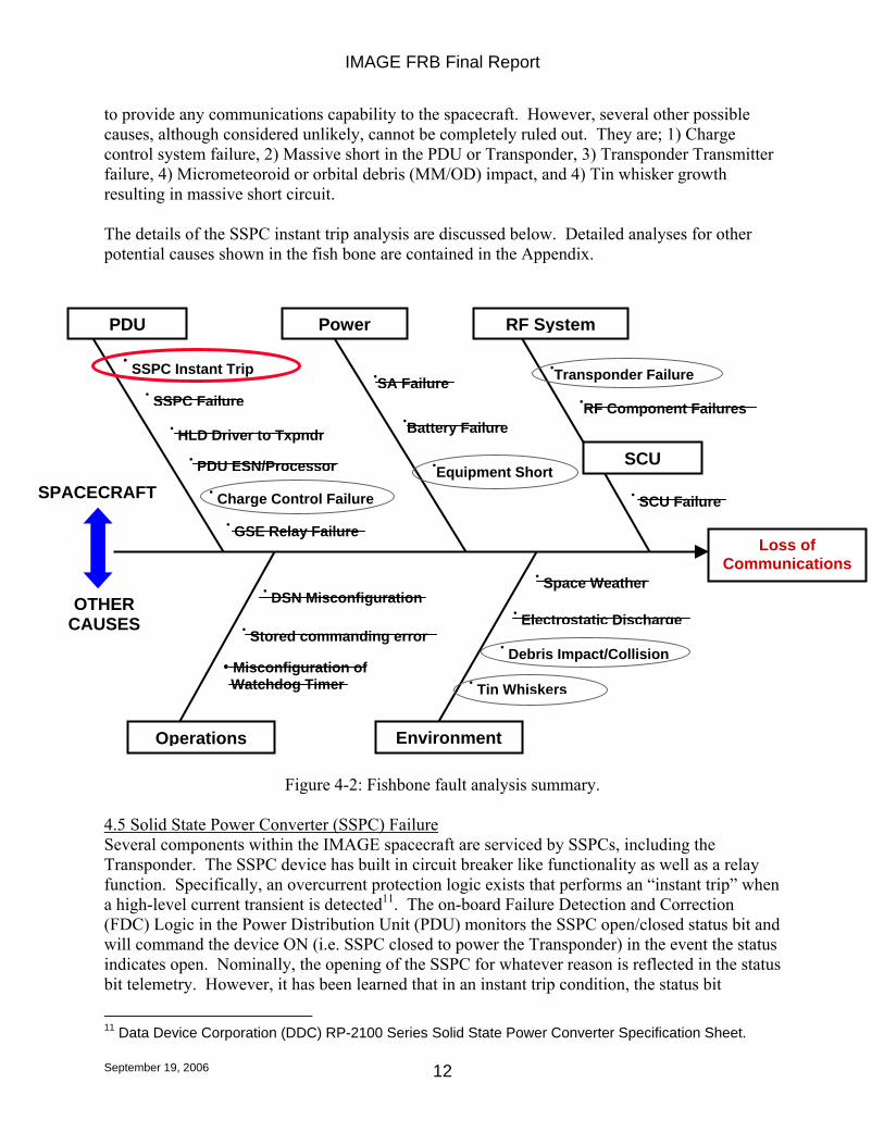
Figure 4-1: Summary of AMOS and thermal model temperature comparisons. 4.4 Fault Tree Summary Applying the fault analysis guidelines discussed above resulted in the “fish bone” fault hierarchy depicted in Figure 4-2. The faults considered are subsumed into two general classes; those that fall into a spacecraft subsystem/functional grouping (in the upper part of the diagram) and all others. The subsystem/functional groups are: 1) Power Distribution Unit (PDU) covering power electronics, relays, etc, 2) Power covering power generation equipment including the Solar Arrays, Batteries, as well as general equipment shorting that directly effects the power system, and 3) the RF System that covers the Transponder (Transmitter and Receiver) and RF components such as antenna, diplexers, relays, etc. The ‘other’ class is split into operational and environmental groups. The result of the fault analysis was that the most likely root cause of the loss of communication event was a loss of communication capability due to the Transponder SSPC inadvertently opening (an instant trip event). This would put the Transponder into an unpowered state unable
9 This is the primary reason that the temperature rise expected by turning on the CIDP and HENA heaters would not be detectable by AMOS observations. The area ratio between the solar panels and the equipment radiators (from which heat is rejected by onboard equipment) is 9:1. 10 The GaAs arrays are ~18% efficient, producing ~12 A. Power that is not used is shunted and effectively left on the array, which manifests as thermal energy. The bus draws approximately ½ of that (~6A) for both the nominal and safemode cases and 0 A for the ‘dead’ case. But the difference in power left on the arrays among these different operational scenarios results in only a small temperature difference since the array temperature is mostly dominated by the absorption of incident sunlight not converted to electrical power.
250 K 310 K AMOS Measurements
260 K 306 K Thermal Model: Dead
258 K 303 KThermal Model: Safed
Beginning of Observation End
+/- 2 K
+/- 5 K
+/- 5 K
IMAGE FRB Final Report
September 19, 2006
12
to provide any communications capability to the spacecraft. However, several other possible causes, although considered unlikely, cannot be completely ruled out. They are; 1) Charge control system failure, 2) Massive short in the PDU or Transponder, 3) Transponder Transmitter failure, 4) Micrometeoroid or orbital debris (MM/OD) impact, and 4) Tin whisker growth resulting in massive short circuit. The details of the SSPC instant trip analysis are discussed below. Detailed analyses for other potential causes shown in the fish bone are contained in the Appendix.
Figure 4-2: Fishbone fault analysis summary.
4.5 Solid State Power Converter (SSPC) Failure Several components within the IMAGE spacecraft are serviced by SSPCs, including the Transponder. The SSPC device has built in circuit breaker like functionality as well as a relay function. Specifically, an overcurrent protection logic exists that performs an “instant trip” when a high-level current transient is detected11. The on-board Failure Detection and Correction (FDC) Logic in the Power Distribution Unit (PDU) monitors the SSPC open/closed status bit and will command the device ON (i.e. SSPC closed to power the Transponder) in the event the status indicates open. Nominally, the opening of the SSPC for whatever reason is reflected in the status bit telemetry. However, it has been learned that in an instant trip condition, the status bit
11 Data Device Corporation (DDC) RP-2100 Series Solid State Power Converter Specification Sheet.
Loss of Communications
SCU
• DSN Misconfiguration
Operations
PDU
•Transponder Failure
Power RF System
•SA Failure
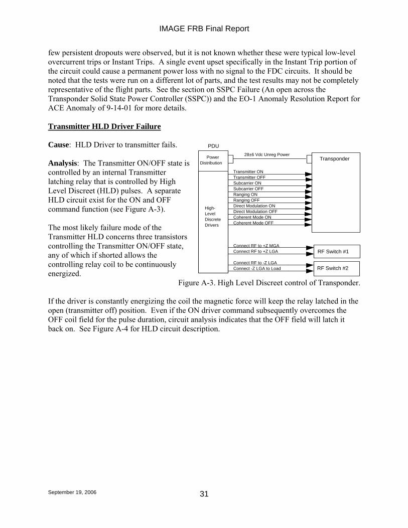
• HLD Driver to Txpndr
• Stored commanding error
• SSPC Instant Trip
•RF Component Failures
• PDU ESN/Processor
• Charge Control Failure
• GSE Relay Failure
•Battery Failure
• SSPC Failure
•Equipment Short
• Space Weather
• Debris Impact/Collision
• SCU Failure
• Electrostatic Discharge
Environment
• Misconfiguration of Watchdog Timer
SPACECRAFT
OTHER CAUSES
• Tin Whiskers
IMAGE FRB Final Report
September 19, 2006
13
telemetry does not accurately reflect the SSPC status (i.e. the status indicates the SSPC is ON when it has actually tripped to an OFF state). This prevents the on-board FDC logic from detecting the device is OFF and attempting to reset it to ON, resulting in the device remaining OFF. In addition to a massive short circuit, the instant trip condition can also be caused by a radiation induced SEU in the SSPC. An SEU induced instant trip was attributed as the root cause of three previous on-orbit anomalies on the EO-1 and WMAP missions. The lack of status telemetry for the instant trip condition was not known until the investigation into the first EO-1 anomaly was completed in September 2001 (well after IMAGE had launched). The result of that investigation12 revealed that the lack of proper status following an instant trip event was actually part of the part’s design, but had not been reflected in any part documentation provided to the users. This prevented the PDU designers from incorporating an FDC logic design that could properly incorporate the part’s expected behavior under these circumstances. The OFF condition of the SSPC is recoverable by cycling the command line to the device (which requires an OFF command followed by an ON command). For other than the Transponder SSPC, this could be performed via ground command. However, all ground commands are prevented from being received under the assumed scenario since the Transponder SSPC in an OFF state means that the Transponder itself is OFF (Receiver and Transmitter sections are OFF). Additionally, even if the command sequence could be sent from an on-board stored command load or macro within the SCU, it would be rejected by the PDU (by design). By design, the PDU is the only entity that can control the state of the Transponder SSPC and it will always try to ensure that it is ON, as discussed above. The only avenue identified that could cause the PDU to reset (OFF-ON sequence) the Transponder SSPC is a complete bus reset induced by a low voltage condition (<21 Vdc) which might occur during the next deep eclipse cycle in October 2007. This is discussed in more detail in the subsequent section. Additional technical details regarding the SSPC instant trip failure scenario are contained in the Appendix.
12 EO-1 Anomaly Resolution Report for ACE Anomaly of 9-14-01.
IMAGE FRB Final Report
September 19, 2006
14
5. Mission Recovery Possibilities 5.1 Introduction Due to the fact that the likely cause of the anomaly is the result of an SSPC instant trip event, it may be possible to recover the mission given the right set of circumstances that would allow the SSPC to be commanded back ON. The FRB identified a scenario under which this may occur. When the spacecraft passes through an eclipse of sufficient duration a deep main bus voltage sag may result in a complete bus reset upon leaving the eclipse. The bus reset performs the same SSPC OFF-ON sequence of commands occurring during initial spacecraft separation and results in the Transponder in an ON state. This may occur during the October 2007 eclipse season, which has been identified to be of sufficient duration. However, two parameters in the analysis for which a relatively large error of uncertainty exists render this outcome tentative; 1) the predicted bus voltage sag, and 2) the main bus voltage level that invokes the reset. These uncertainties and the analysis description are discussed in more detail below. 5.2 IMAGE Eclipse Possibilities IMAGE’s orbital precession places the apogee in the Ecliptic for long durations at roughly 3 ½ year intervals. The resulting eclipse periods can exceed two hours in duration for which the spacecraft power system was never initially designed (due to the fact that IMAGE’s nominal two-year mission profile at launch would have never taken it through such a period). Similar long eclipse periods were handled during the extended part of the mission by payload pre-heating followed by intentional load shedding prior to the eclipse entry. This allowed for science instruments and bus components to retain temperatures above survival limits while also reducing battery draw down during the eclipse period. Due to the current situation this strategy cannot be implemented. However, analysis indicates that temperature limits to which observatory components were tested will not be exceeded during the next deep eclipse period13. The fact that the spacecraft was not designed to handle deep eclipses is, in fact, what is vital to its possible revival. The next deep eclipse period will be in October 2007 with the longest period of darkness lasting ~160 minutes. 5.3 Analysis Discussion The goal of this analysis is to ultimately determine whether the October 2007 deep eclipse period will be sufficient in duration to result in the desired main bus reset and consequent Transponder turn ON. An outline of the analysis is provided below. Supporting details are provided in the FRB’s Final Presentation. 5.3.1 Estimated Bus Loading The approach taken was to first model the bus loading during the eclipse period given the presumed state of the spacecraft under the most likely failure scenario noted previously. The spacecraft was assumed to have the full functionality existing during the last contact. Entry into the eclipse period would be in safemode since safemode state would be internally commanded
13 The "survival" temperatures as defined in the specifications will be exceeded. Those are the temperatures at which the "survival" heaters will maintain components until power is removed from them. However as the spacecraft bus components and instruments were tested to 10 deg. C beyond those "survival" limits, there is assurance that they will survive the long eclipse nevertheless, since the excursion outside of the "survival" limits is predicted to be less than that.
IMAGE FRB Final Report
September 19, 2006
15
after not receiving commands for a period exceeding 72 hours14. Additionally, the Transponder was assumed to be in an OFF state consistent with the failure scenario. Bus loading during the eclipse was assumed to occur in three distinct phases; 1) the loading defined by the safemode state upon eclipse entry up until survival heater activation, 2) the loading after survival temperatures are reached and survival heaters are activated until a 30% battery State of Charge (SOC), and 3) the loading after the battery 30% SOC alarm triggers that performs final load shedding. Underlying assumptions about temperature decline rates to survival levels, and survival heater turn-on and current draw profile were taken from actual on-orbit data during previous eclipses. Two previous eclipse periods were used to model the above three phases. The March 31, 2003 eclipse (duration ~75 minutes) was marked by an unintentional battery run down resulting from an attempt to warm up the spacecraft in preparation for the cool down of systems expected during eclipse15. The run down invoked a load shedding from the onboard Power Distribution Unit (PDU)16 that resulted in a safemode state very similar to the presumed current state of the spacecraft. The resulting bus loading was used as an estimate for both initial eclipse entry and post 30% SOC phases. Corrections were made for differences due to the Transponder OFF state of the current configuration (true for all phases) and survival heaters being turned OFF after 30% SOC is reached. The resulting average bus loading for the 2007 eclipse entry phase was estimated at 4.15A +/-5%, lasting for approximately one hour (+/- 10 minutes, see below) during which survival heaters would not be active. The middle load phase (i.e. after survival heater turn ON until 30% SOC is reached) was estimated from spacecraft performance during the April 8, 2003 eclipse (duration ~120 minutes). Equipment cool down rates from entry temperature levels to survival levels were estimated to be from 10-15 deg. C per hour from the long and uniform cool down period that occurred during the eclipse. Applying this lapse rate to the estimated initial entry temperatures resulted in an estimate of one hour to reach survival temperatures after eclipse entry. Bus loading after survival heater activation during this eclipse was seen to be a rough average of 9A with significant variation (peaks up to 12 A). This is due to mechanical thermostats and the random phasing of the heater activation. Using this data, bus loading during this phase for the October 2007 eclipse was estimated to be 9A +/- 16%. If survival heater activation continues for a sufficient duration, the higher bus loading will draw the battery SOC down to a level of 30%17. When the 30% level is reached, the PDU will turn OFF all heaters and the Transmitter (already OFF in this scenario) without delay. After 30
14 The SCU commands a reboot after expiration of its 72 watchdog timer. The reboot sequence puts the spacecraft in safemode. 15 Heater loads were in excess of available bus power causing a negative power margin and battery run-down. 16 At 50% SOC, power to the Payload is reduced. At 40% SOC, the SCU will safely power off the Payload, Star Tracker, Magnetic Torquer System, and Sun Sensor. Furthermore, at 30% SOC, the SCU will halt keep-alives to PDU causing the SCU to reboot after 30 minutes. Thermistor Heaters and PL survival heaters are Powered OFF with no delay. 17 The 30% level will always occur after exactly 14.7 Ahr have been withdrawn from the battery since the SOC is calculated based on the nameplate battery capacity of 21 Ahr and not the real current capacity, which is different.
IMAGE FRB Final Report
September 19, 2006
16
additional minutes the PDU will power OFF the SCU after which only the PDU is still ON The load current for this sequence was estimated using the March 31 eclipse data by taking the base level current between heater activation periods (in “warm” conditions just prior to eclipse entry), which was estimated at 2.3 A. Subtracting the Transponder current of 1.1 A gives a current level of 1.2 +/-0.1 A for the 30 minute period prior to the SCU being turned OFF. After the SCU is off the load drops by 0.7 A to a level of approximately 0.5 +/-0.1 A, which is the terminal load current until a potential bus reset occurs. 5.3.2 Estimated Battery Discharge Profile An attempt was made to model the battery discharge curve (time-voltage curve during draw down) for the anticipated loading conditions described above. The methodology consisted of starting from an ideal discharge curve taken from pre-launch battery test data, then extrapolating that to account for battery aging, different actual vs. Flight Software assumed (i.e. nameplate) initial battery capacity, anticipated October 2007 eclipse load profile, etc. Two discharge curves were generated, the first assuming a best estimate current profile as described above. The second was generated assuming best case/maximum current draw that was calculated by taking the nominal values and favorably adding the error uncertainties. The ideal battery discharge curve was modeled from Crane capacity test data of an IMAGE NiCd test pack (see Life Cycle Test of IMAGE Pack B300A) since no on-orbit capacity measurements had been performed during the mission (capacity testing is not possible with the IMAGE power system design). The capacity test curve (from the test data) with the maximum number of cycles was used since this represented a “battery age” closest to the on-orbit age of the IMAGE battery at the time of the Oct 2007 eclipse (2.6 years vs. 7.5 years). The right-most part of the curve was scaled to the left to a capacity amount representing the estimated capacity on October 2007. This was performed by taking the estimated original capacity of the flight battery at launch (24.6 Ahr) and then applying an estimated capacity loss/degradation to account for its 7.5 age. That degradation rate was initially also calculated from the test data by comparing the capacity measurement from the lowest cycle to the largest cycle test curves and then computing an average capacity loss rate by converting the cycle values to equivalent years (using the average number of eclipses per year as cycles per year). The approximate capacity loss rate was estimated at 1.62 Ahr/year using this method. The capacity loss value was then applied to the original capacity of the flight battery at launch, yielding 14.25 Ahr. Next, the capacity estimate was increased to account for an estimated lower average load current during the eclipse than the test data was taken at (6.3 A vs 11 A)18. This raised the estimate to a value of 16.4 Ahr. The adjusted capacity curve is then scaled up in voltage by a factor 22 since the test data was taken for a single cell while the flight battery is 22 cells in series. The capacity curve time scale is then converted to equivalent orbit time for the October 2007 eclipse scenario by using the load profile curve discussed above (by calculating the time to discharge to the indicated capacity under the eclipse load current profile). The final result is an idealized discharge curve scaled for on-orbit load current profile and battery age. See Figure 5-1 for the discharge curves for nominal and best case bus loading, respectively. 18 Rule of thumb is that capacity gain is ~15% per 5 A reduction in discharge rate.
IMAGE FRB Final Report
September 19, 2006
17
Figure 5-1: Eclipse Discharge Summary for Nominal and Best Case Load Estimates.19
5.3.3 Reset Determination The possibility for the desired bus reset is now very simply determined by observing whether the time required to pull down the bus voltage to the reset level is less than the duration of the longest eclipse of the October 2007 eclipse season. As can be seen from the two charts above, only in the case where the reset level is 24 V and under a best case loading scenario is a reset likely. The actual bus reset level assumption had been 21 V throughout most of the FRB
19 The discharge profile (current, capacity out, and voltage) is carried out past the eclipse end time using eclipse period trends for illustration purposes only.
0
5
10
15
20
25
30
35
0 1 2 3 4 5 6
Eclipse Period Sun Period
160 Minutes(2.7 Hours)
2.7
21 V
24 V
Reset Possibility:Best case loading w/24 V
PDU reset level.
At 14.7 AH outS/C Calculated SOC is 30% and all loads are shut down except the PDU and SCU.
The SCU is shut off 30 minutes later.
Bus Voltage Best Case LoadBus Voltage Nominal Load
Battery Capacity Out Best Case LoadBattery Capacity Out Nominal Load
Battery Current Out Best Case LoadBattery Current Out Nominal Load
Eclipse Time, hours
Vol
tage
(vol
ts),
Cur
rent
(am
ps),
Cap
acity
Out
(Am
p-ho
urs)
0
5
10
15
20
25
30
35
0
5
10
15
20
25
30
35
0 1 2 3 4 5 60 1 2 3 4 5 6
Eclipse Period Sun Period
160 Minutes(2.7 Hours)
2.7
21 V
24 V
Reset Possibility:Best case loading w/24 V
PDU reset level.
At 14.7 AH outS/C Calculated SOC is 30% and all loads are shut down except the PDU and SCU.
The SCU is shut off 30 minutes later.
Bus Voltage Best Case LoadBus Voltage Nominal Load
Battery Capacity Out Best Case LoadBattery Capacity Out Nominal Load
Battery Current Out Best Case LoadBattery Current Out Nominal Load
Bus Voltage Best Case LoadBus Voltage Nominal Load
Battery Capacity Out Best Case LoadBattery Capacity Out Nominal Load
Battery Current Out Best Case LoadBattery Current Out Nominal Load
Bus Voltage Best Case LoadBus Voltage Nominal Load
Battery Capacity Out Best Case LoadBattery Capacity Out Nominal Load
Battery Current Out Best Case LoadBattery Current Out Nominal Load
Eclipse Time, hours
Vol
tage
(vol
ts),
Cur
rent
(am
ps),
Cap
acity
Out
(Am
p-ho
urs)
IMAGE FRB Final Report
September 19, 2006
18
investigation since it is cited in the PDU FSW requirements document. Only toward the end of the investigation did it come to light that the same document also referenced 24 V as the actual reset level. Additionally, there is strong circumstantial evidence (but no direct observation) that the spacecraft actually went through a bus reset at 24 V during the eclipse of April 8, 2003. The uncertainties of the actual bus reset voltage and other uncertainties in the above analysis are further examined in detail in the FRB’s Final Presentation Charts. At whichever voltage it occurs, the bus reset has the effect of putting the spacecraft’s PDU in a “pre-breakwire” mode identical to the launch vehicle separation readiness state. Additionally, all bus loads are turned OFF, including those that remained ON after the 30% SOC alarm is reached. As a result, the Transponder is shut down via its SSPC commanded to OFF. Once eclipse exit occurs and the bus voltage rises (to 1 V above the reset level) then the separation turn-ON sequence is executed by the PDU. The SCU and Transponder are powered ON (by commanding their SSPCs to ON) and the reboot macro is executed which also turns the Transmitter ON with 44 Kbps telemetry active in Omni mode. Payload heaters are turned ON in normal mode. 5.3.4 Post Eclipse Reset and Recovery Thermally, the IMAGE observatory will very likely survive the October 2007 eclipse with no damage. Estimates of the lowest temperatures reached during the eclipse were performed by using actual on-orbit data measurements of equipment cool-down rates during the previous April 8, 2003 eclipse (as discussed above). Since all Observatory elements were tested to a 10 degree C margin below the “Survival Minimum”, no damage is likely to occur for at least one hour after survival heaters are OFF, which is well past the longest duration October 2007 eclipse period. If the IMAGE RF signal is detected on October 2007 (indicating a bus reset occurrence as postulated) then the mission will be operated as it was previously – including future eclipse operations using stored commands to drive temperatures to survival-max between eclipses, and survival-min during eclipses. There will be a brief science re-commissioning program conducted in which payload elements are brought back up to operational mode in a step by step manner to carefully assess their operational state by comparing measurements with previous values. The spacecraft bus will only require limited re-commissioning efforts that will consist of reorienting the spin axis to orbit normal (to minimize the gravity gradient torque). Some safing limits adjustments will be considered, including adjustments to provide better recovery response to a future SSPC instant trip anomaly.
IMAGE FRB Final Report
September 19, 2006
19
6. Lessons Learned The IMAGE FRB was able to derive four lessons learned of a general nature that other NASA missions may find relevant and useful to both their development and operations phases. They relate to the areas of hardware redundancy, part anomaly reporting, design documentation, and the management of operational limits. The lessons are cited below along with pertinent discussion and rationale. Lesson #1: The Transponder Receiver should have redundancy built into its power switching or the sensed operational status – even if the mission is designed as single string throughout. Generally speaking, the hardwiring of the Receiver power to the power bus is typical industry wide practice in the design of spacecraft communications systems in the recognition that loss of the ability to command the vehicle is a total loss of mission. Thus, overcurrent protection of the receiver to protect the other bus components against a fault offers additional safeguard during operations only if the protection device resets (in a robust and redundant manner) after transient faults in either the receiver or the overcurrent protection device itself. In fact, there is currently a proposed GSFC “golden rule” that addresses that the Receiver should be permanently connected to the bus with only the Transmitter switched. If a switched design is chosen then additional redundancy should be provided to prevent the switching device itself from becoming a zero fault tolerant point in the design20. Either redundant parallel switching or redundant sensed status of the switch’s state can accomplish this so that automatic on-board FDC logic can correct an inadvertent misconfiguration. In the case of IMAGE’s communications system design, the use of an SSPC to power the Transponder (Receiver and Transmitter) seems to have been chosen as a ‘smart’ replacement for the typical fused supply for the Transmitter. Arguably, this allowed more flexibility during I&T testing and, theoretically, provided the same (and more) circuit protection. Additionally, the desire was to have the Transponder OFF during ascent, which could be more easily accomplished by a switched design (as noted above the SSPC offers both switching and circuit breaker type functionality). The early communications system design actually shows two of them connected in parallel, but does not say whether this was to handle higher output currents or for redundancy considerations. Later diagrams show only one SSPC. Integrated Circuit (IC) board space constraints were likely the reason for using only one SSPC as indicated by conversations with design engineers, although this rationale was not indicated in any design documentation that the FRB could uncover. Lesson #2: Part anomaly alert processes should be more inclusive to operations personnel. If it could include alerts to missions that are using the part, then some preventive operational mitigation might be put into effect. 20 It should be noted, as discussed earlier, that the PDU design did incorporate sensing of the SSPC’s state. However, the design did not anticipate potential problems with the sensing function itself (in this case in the form the instant trip phenomena). The Board does not intend to label this a design mistake or oversight since the low budget, fast track development, and single string design philosophy made such a design outcome understandable and reasonable at the time. However, the FRB wishes to note, for posterity’s sake, that future designs should at least consider and preferably incorporate the cited lesson.
IMAGE FRB Final Report
September 19, 2006
20
Quality assurence support to operational missions should include their participation in the investigation of mission operational anomalies, the generation of SOARS anomaly entries as appropriate, the generation of appropriate GIDEP reports, and the generation of NASA Alerts on associated parts problems with operational personnel on distribution. Wider distribution of NASA Alerts would allow better dissemination of part anomaly data. The distribution should include Mission Directors of operational missions and contractors working on NASA missions (the current distribution is mostly limited to hardware development personnel). Having Mission Directors and Operational Managers directly in the notification distribution allows them to pursue investigative and mitigation actions at the earliest possible time. Following this line of reasoning, knowledge of the EO-1 SSPC anomaly21 should have been properly passed onto MAP and IMAGE operations to allow the early identification of similar susceptibility and possible safeguards to be implemented22. As it turns out, having this practice in place at the time of the first noted SSPC anomaly could not have prevented the IMAGE anomaly due to the fact that there is no mitigation (discussed elsewhere) allowed by the spacecraft’s design. However, it is still potentially useful for other mission scenarios (even if no mitigation action is possible) since the prioritization of science targeting may be adjusted with the knowledge of the anomaly and its estimated probability of occurrence. Lesson #3: Complete & accurate as-built design documentation is essential for anomaly resolution. As-built documentation should include a searchable parts list. The utility of a parts list is a strong function of how complete it is and how readily it can be searched. Ideally, parts lists for all NASA missions would be in a similar electronic format that allows for readily harnessing the full power of modern database tools. Such a capability within a mission and across all missions would aid in any anomaly investigation by allowing for the quick identification of part usage throughout any bus or instrument design. Also, the identification of potential problems on other missions (currently flying or in development) that are utilizing the same or similar parts would be more easily accomplished. The power of such a capability is readily apparent. The Board notes the difficulty of implementing a complete system since component suppliers purchase subassemblies and parts from their subcontractors, which themselves may not have a complete parts list program in place (or may not be capable of supplying parts databases in the proper electronic format). Additionally, several FRB members who had experience in parts management, testing, and failure analysis noted that as-built parts lists are often not delivered, even though specified in the contract. The reasons for this are varied, however NASA Project management must share some responsibility since stronger enforcement of contract performance was identified as part of the solution.
21 IMAGE was launched on March 25, 2000. The first EO-1 SSPC anomaly occurred on September 14, 2001. The second EO-1 SSPC anomaly occurred on a Wide-band Advance Recorder Processor (WARP) on August 25, 2004. The MAP SSPC anomaly occurred on February 17, 2005, while the IMAGE SSPC anomaly occurred on Dec. 18, 2005. 22 Neither a GIDEP report nor a NASA Alert was issued as a result of the first SSPC anomaly. The lead power engineer on the EO-1 SSPC investigation did submit an email request for Quality Assurance to create a GIDEP entry. However, the FRB was unable to determine why the GIDEP report was never created.
IMAGE FRB Final Report
September 19, 2006
21
Finally, accurate and complete as-built design documentation in the form of drawings and schematics is of equal importance. During the IMAGE investigation the Board underwent considerable initial difficulty in determining whether the Transponder power was in fact supplied by an SSPC since the switched design was not depicted in either schematics or PDR or CDR presentation packages. The Board wishes to remind readers that the need for accurate as-built documentation was a finding of the Columbia Accident Investigation Board (CAIB Report section 10.3) as well. Although the CAIB findings cited here are specific to Space Shuttle operations, their generality should be readily evident and applicable to all of NASA’s space missions. Lesson #4: Safing limits & operational procedures related to battery SOC should be adjusted to account for battery degradation as the mission progresses past the nominal lifetime. Without safing test threshold adjustments, a test’s margin is slowly eroded until the test’s purpose is in effect, nullified. In the case of IMAGE, the Battery 30% SOC test now trips at near depletion of the current predicted usable battery capacity. Load shedding is thus performed well after the point at which it would be useful. Adjustments should be assessed and implemented on a regular basis, if possible, to preserve safing test margins and safing response utility. The uncertainty of the prediction of battery capacity (or other system parameters) on which thresholds are based must also be assessed and factored into any threshold adjustment. Since the IMAGE mission was originally designed for a nominal two-year mission lifetime and no provision was made for performing battery capacity testing, only analytical estimates could have been made containing a relatively large uncertainty. Even so, the Board noted that the IMAGE mission might have benefited from limited adjustments in Battery SOC computation parameters and test trigger levels during some of the longer eclipses. Although the PDU FSW (where battery SOC is actually calculated) was never designed to be updated, its design allows the coefficients used in the amp-hour discharge computation and the estimated battery "nameplate" capacity to be adjusted. Additionally, the SCU FSW was designed to be updated allowing changes in all safing test algorithms and parameters (since they are maintained as FSW table parameters). Finally, the Board recognizes that mission planning for the extended mission period is difficult to perform in a fast paced and frugal project environment like IMAGE. Provisions to implement additional capabilities in FSW and operations procedures and process for safing test management may not typically be encompassed since they may not be explicitly identified as mission requirements. Thus, the Board also recommends that Project management, in the early stages of design, consider the possibility of an extended mission and it implications to flight operations and hardware/software capability. Such consideration will likely identify key capabilities that can be implemented cheaply at that time.
IMAGE FRB Final Report
September 19, 2006
22
7. Conclusions The Board’s main conclusion is that it is likely IMAGE became unable to continue routine communications due to an instant trip of the SSPC supplying power to the Transponder. The instant trip left an essentially fully functioning and healthy spacecraft in an inoperable state due to its Transponder being unpowered. Several other possible, but very unlikely, causes exist for the loss of communications capability that cannot be completely eliminated. These are; 1) Charge system control failure, 2) Equipment short resulting in power system destruction, 3) Transponder failure, 4) Debris impact causing massive power system failure, 5) Tin Whisker growth resulting in massive power system shorting and failure. Given the primary failure conclusion, all spacecraft subsystems and science instruments are believed to be capable of fully continuing the IMAGE science mission if the spacecraft can be recovered. The recovery of the mission may be possible during the October 2007 eclipse season due to the fact that the main bus voltage sag during the extended eclipse may permit a main bus (and resulting Transponder SSPC) reset, however, this is not likely given that the reset level may really be 21 Vdc. There is strong evidence that the reset level is actually 24 Vdc, which if true would greatly increase the probability of a reset. Nevertheless, even under this scenario, a reset and return to science operations cannot be guaranteed since optimistic assumptions concerning the battery discharge curve and bus loading must also be realized. The flight operations for the IMAGE mission have been put into a standby mode to await the October 2007 eclipse season. If the bus (and SSPC) reset occurs then the IMAGE RF downlink will be detected and command operations to bring the spacecraft out of safehold can commence, followed by the resumption of science shortly thereafter with no expected limitations. If the spacecraft does not revive, the IMAGE End of Mission Plan will be executed. If the mission does revive, however, a recurrence of the anomaly is possible and cannot be prevented. This is due to primarily to the fact that the PDU software is not patchable by design. Additionally, although commands can be strategically placed within the SCU (for example, within the safemode recovery macro or even the nominal command load) to command a reset of the Transponder SSPC, such commands would be rejected by the PDU by design. However, the Board does note that there are several mitigation options that may be incorporated to allow a more rapid recovery from a future event. Although the PDU software cannot be patched, the bus reset level (the value of 24 Vdc or 21 Vdc) can be changed by ground command. It may be advantageous to raise the reset level and simultaneously adjust SCU safing thresholds to increase the likelihood of a reset during eclipses of shorter duration (which occur annually in contrast to the deep eclipses that occur approximately every 3 and 3.5 years). This can be accomplished by lowering all the SCU safing threshold limits to allow the maximum bus load to persist during an eclipse. Although, if successful, the result would be more frequent safemode entries and minor disruptions to science operations, there would also be less time needed to recover following any future repeat of the anomaly. The Board also notes that the previous anomaly history of IMAGE was not a harbinger of the current failure. However, the anomaly history of EO-1 and WMAP were with respect to the three previous SSPC anomalies that have been discussed. Finally, the operational response to the anomaly was timely, appropriate, and complete. The Board finds that nothing additional could
IMAGE FRB Final Report
September 19, 2006
23
have been done by the operations team in dealing with the immediate lost communications event that occurred on December 18, 2005.
IMAGE FRB Final Report
September 19, 2006
24
Appendix: Fault Analysis Cases POWER Battery Failure Case 1 Cause: Battery internal short. Analysis: The battery consists of 22 individual cells in a series configuration. An internal short in a single cell would change the power bus impedance by a small amount but not alter it enough to affect equipment operation. Due the changed impedance, a shift in bus voltage would likely occur. However, since the bus design can accommodate voltage ranges from 24 to 32 VDC, there would likely be no disruption to the overall operation of the power system. Only multiple simultaneous cell shorting could effectively short the bus and fail the spacecraft power system resulting in complete loss of communications. Conclusion: IMAGE has no history of battery anomalies (see Figure A-1 for typical trending data). All available telemetry showed healthy batteries and no indication of cell shorting or other battery degradation. The probability of multiple battery cells shorting over a short period (~8.5 hours23) is highly improbable. Battery shorting is not a likely cause for the failed communication capability. Battery Failure Case 2 Cause: Battery open cell. Analysis: The battery consists of 22 individual cells in a series configuration. Thus, any single cell suffering an open circuit type failure would halt the ability of the battery to generate any current and service the load. Additionally, since the battery regulates bus voltage, the bus voltage during eclipse would be zero as the bus capacitance quickly discharges. During sunlight the entire array is on the bus until the overvoltage protection clamps the bus voltage to a maximum 35V. Conclusion: The loss of communications event occurred during a period of continuous sunlight (no eclipse). A battery cell open failure would have resulted in bus voltage being maintained to a value of 35V maximum. That in turn would have allowed the Transponder to continue to function with no loss of signal or reception capability. Thus, a battery cell (or even multiple cell) open failure could not have resulted in the loss of communications capability.
23 The time period between the first missed contact and the previous successful contact was approximately ~8.5 hours.
IMAGE FRB Final Report
September 19, 2006
25
Figure A-1. Battery/bus temperature and voltage trends under typical loading.
Solar Array Failure Cause: Solar array failure (short or open). Analysis: The solar array consists of 8 side panels and 2 end panels. The side panels are comprised of 6 parallel strings each having 44 cells in series. The end panels are comprised of 8 parallel strings each having 68 cells in series. The cells are GaAs/Ge technology. The strings from the panels are grouped into 6 segments feeding power into the Power Distribution Unit (PDU). Each panel is grounded to the spacecraft structure. The most likely failures of the array would probably involve a short or open in a single segment between the array and PDU, an open in a single panel ground or an open or short of a cell in a string. A short or open somewhere between the array and PDU will most likely affect the output of a single panel. But even if all the strings forming a segment from the array panels short before the PDU input, the spacecraft would lose only about 16% of available power. There would be no significant loss of spacecraft functionality.
BSOC T_batt V_batt V_bus I_load I_batt
IMAGE FRB Final Report
September 19, 2006
26
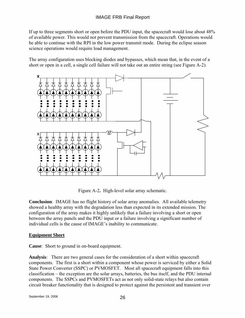
If up to three segments short or open before the PDU input, the spacecraft would lose about 48% of available power. This would not prevent transmission from the spacecraft. Operations would be able to continue with the RPI in the low power transmit mode. During the eclipse season science operations would require load management. The array configuration uses blocking diodes and bypasses, which mean that, in the event of a short or open in a cell, a single cell failure will not take out an entire string (see Figure A-2).
Figure A-2. High-level solar array schematic.
Conclusion: IMAGE has no flight history of solar array anomalies. All available telemetry showed a healthy array with the degradation less than expected in its extended mission. The configuration of the array makes it highly unlikely that a failure involving a short or open between the array panels and the PDU input or a failure involving a significant number of individual cells is the cause of IMAGE’s inability to communicate. Equipment Short Cause: Short to ground in on-board equipment. Analysis: There are two general cases for the consideration of a short within spacecraft components. The first is a short within a component whose power is serviced by either a Solid State Power Converter (SSPC) or PVMOSFET. Most all spacecraft equipment falls into this classification – the exception are the solar arrays, batteries, the bus itself, and the PDU internal components. The SSPCs and PVMOSFETs act as not only solid-state relays but also contain circuit breaker functionality that is designed to protect against the persistent and transient over
x
x
IMAGE FRB Final Report
September 19, 2006
27
currents characteristic of a short, prior to damage. Any large short circuit would trip the overcurrent circuit breaker logic and remove power from the troubled component. This would be reported in telemetry and no loss of communication capability would occur. The exception for this is the Transponder that is also sourced via an SSPC. Because the state of the Transponder’s SSPC is monitored by the PDU’s Failure Detection and Correction (FDC) logic to assure the Transponder is constantly powered, any SSPC trip due to a short would cause the FDC to close the SSPC. If the short had not cleared itself then the trip would occur again followed by reapplication of power to the Transponder. The cycle would presumably repeat ad infinitum. It is questionable, determined by the nature of the short, whether the time dynamics and particular internal Transponder failure would allow intermittent CW that would be detectable by a ground station. However, the instant trip function24 of the SSPC is not detected by the FDC logic. Thus, an instant trip of the SSPC servicing the Transponder (for whatever reason) is not recoverable via the FDC or any other on-board spacecraft function. This is covered more fully in a separate analysis. The second general case is a short in equipment and systems not protected by the circuit breaker functionality of an SSPC or PVMOSFET, and not fused. A massive short in one of these components would result in a drastic reduction of bus voltage and the general failure of the power system that would be unrecoverable. A certain loss of communication would result. Separate analysis covering Solar Array and Battery shorting is provided elsewhere. Note that a low level short insufficient to result in a SSPPC or PVMOSFET trip, or equipment damage may manifest in a chassis current if the short is to ground. IMAGE has experienced a persistent low-level chassis current since launch that has been sourced to the battery heaters, payload deck heaters, FUV instrument heater and solar arrays. The chassis current has never had any detectable effect on the spacecraft or payload. Additionally, mission scientists have been queried and have noted no detectable impact to science data quality. The level of current is not enough to affect the gate bias of the Transponder SSPC making it more susceptible to instant trips. Given the magnitude, trend, and history of the chassis current, there is no evidence that it was progressing toward catastrophic growth and is the cause of a massive power system failure, or was the cause of an SSPC instant trip (see section on SSPC instant trip)25. Conclusion: Although highly unlikely, a sudden massive short in unswitched equipment (i.e. PDU itself) or in the Transponder cannot be ruled out as a possible cause. Power Distribution Unit (PDU) SSPC Failure Case 1 Cause: An open across the Transponder Solid State Power Controller (SSPC).
24 The instant trip function is invoked for large and short lived current spikes and is a separate overcurrent protection circuit within the SSPC. 25 See IMAGE FRB Final Presentation, March 21, 2006 for a detailed analysis of the chassis current sources.
IMAGE FRB Final Report
September 19, 2006
28
Analysis: Most spacecraft equipment is switched via an SSPC or PV-MOSFET (see Equipment Short case). The failure of the Transponder SSPC would cause the Transponder to cease functioning (both Transmitter and Receiver) since it would, in the worst case, be unpowered. Several cases exist for the possible failure of the Transponder SSPC as discussed below.
• A possible failure scenario for this part is an open of its internal MOSFET. There are ten MOSFETS in parallel inside an SSPC device. All ten would have to fail open in order to lose Transponder power – which is highly unlikely unless there is a total failure in the internal drive circuit.
• SSPC damage due to Total Ionizing Dosage would be a graceful degradation that would manifest as increased SSPC internal losses. The result would be noticeable increases in bus load current. No instant trip or catastrophic failure would result.
• Single-event gate rupture can happen when an energetic particle damages the insulation layer within a MOSFET while it is “off”. However, current understanding of the SSPC part function indicates that the MOSFETs are energized “on” continuously while carrying current to the transponder. Thus, gate rupture is highly unlikely to be a cause of the failure.
Conclusion: An SSPC failure is highly unlikely given the design and operational usage of the part and is therefore not considered as the cause of the loss of communications capability. Supporting Details: Total Ionizing Dose The IMAGE dose-depth curve indicates that the SSPC has received approximately from 30 to 200 krads total dose in an electron-rich environment (based on 100-200 mils aluminum shielding). Though neither the SSPC nor the transponder has been specifically tested, typical total dose damage expected for the SSPC is a graceful degradation of the power passed through the part. The transponder would be expected to draw more current over time that would manifest as an increased bus load current. Eventually the increased current would trip the SSPC (but not an “Instant Trip”), which would engage the FDC process. Based on expected performance, total dose induced damage alone could not produce the IMAGE anomaly, since an SSPC trip would engage FDC processes. In addition, a total dose effect should affect several SSPCs, producing an even greater increase in bus current over time. No such increase was observed. Single-event gate rupture Single-event gate rupture can happen when an energetic particle damages the insulation layer within a MOSFET while it is “off”. Previous single-event radiation testing on similar RP-21000 series parts within rated parameters produced no permanent damage to the MOSFETs. It should be noted that the tests were run on a different lot of parts, and the test results may not be completely representative of the flight parts. Single Event Effects There is a record of radiation susceptibility tests being performed on several generations of the SSPC. However, the results from the tests cannot be correlated to the parts flown on IMAGE.
IMAGE FRB Final Report
September 19, 2006
29
This is significant since the measured susceptibility of the SSPCs manufactured at different times varied in important ways.
Two reports involved an earlier generation of the SSPC (suspected to be a 1995 vintage). Several years elapsed between the launch of IMAGE and the parts included in the 2005 test reports. Change cycles for these types of solid state devices are shorter, about 2-3 years. Also, radiation susceptibility can be influenced by specific design - things like different internal voltage levels etc. Thus, only limited confidence is possible relating the test results to the expected performance of the SSPCs on IMAGE. IMAGE was developed in the “faster, better, cheaper” mode. There was no screening of at least this part; approval was by similarity to other applications. The 2005 tests described the part as highly susceptible to single event transients even at low thresholds (LET = 2.8). These transients typically resulted in the output being toggled off then on for a short duration (approx 0.2 to 1 millisecond). Occasionally, however, the output did not toggle back on until the part was commanded to reset. The part was generally not subject to burnout unless subjected to higher than rated voltages. Under these conditions, burnout was observed down to a LET of 29.9 MeV•cm2/mg. The 2005 data were found to be inconsistent with test data previously made available to the FRB from WMAP that showed that no occurrence of any SEE was detected during testing up to a maximum LET of 80. These tests were conducted for part series SSP-21110, which was an earlier generation of the SSPC model used on IMAGE but from the same manufacturer (i.e., DDC). SSPC Failure Case 2 Cause: SSPC instant trip resulting in an unrecoverable Transponder OFF condition. Analysis: As noted earlier, several components within the IMAGE spacecraft are serviced by SSPCs, including the Transponder. The SSPC device has built in circuit breaker like functionality as well as a relay function. Specifically, an overcurrent protection logic exists that performs an “instant trip” when a high-level current transient is detected26. The on-board Failure Detection and Correction (FDC) Logic in the Power Distribution Unit (PDU) monitors the SSPC open/closed status bit and will command the device ON (i.e. SSPC closed to power the Transponder) in the event the status indicates open. Nominally, the opening of the SSPC for whatever reason is reflected in the status bit telemetry. However, the instant trip condition is not reported by design. This prevents the on-board FDC logic from detecting the device OFF and attempting to reset it to ON, resulting in the device remaining OFF. The instant trip condition can be caused by radiation induced SEU in the SSPC. It was attributed as the root cause of three previous on-orbit anomalies on the EO-1 and WMAP missions. The lack of status telemetry for the instant trip condition was not known until the investigation into the first EO-1 anomaly was completed in September 2001 (well after IMAGE had launched).
26 Data Device Corporation (DDC) RP-2100 Series Solid State Power Converter Specification Sheet.
IMAGE FRB Final Report
September 19, 2006
30
The result of that investigation27 revealed that the lack of proper status following an instant trip event was actually part of the part’s design, but had not been reflected in any part documentation provided to the users. This prevented the PDU designers from incorporating an FDC logic design that could properly incorporate the part’s expected behavior under these circumstances. The OFF condition of the SSPC is recoverable by cycling the command line to the device (which requires an OFF command followed by an ON command). For other than the Transponder SSPC, this could be performed via ground command. However, all ground commands are prevented from being received under the assumed scenario since the Transponder SSPC in an OFF state means that the Transponder itself is OFF. Additionally, even if the command sequence could be sent from an on-board stored command load or macro within the SCU, it would be rejected by the PDU (by design). By design, the PDU is the only entity that can control the state of the Transponder SSPC and it will always try to ensure that it is ON, as discussed above. The only avenue identified that could cause the PDU to reset (OFF-ON sequence) the Transponder SSPC is a complete bus reset induced by a low voltage condition (<21 Vdc) which might occur during the next deep eclipse cycle in Oct 2007. This is discussed in more detail in a subsequent section. Conclusion: An SEU induced instant trip of the Transponder SSPC is the most likely cause of the loss of communications. Potential recovery will not be possible until Oct 2007. Supporting Details: There are three ways the SSPC can turn OFF power to the output or drive the internal MOSFET OFF. These are:
(1) by command, (2) by an overload, (3) by an instant trip.
(a) load hard short circuit (b) by SEU on the current sense circuit.
(3a) The instant trip function requires a current transient of 80A to 120A in about 25usec to open the MOSFET. If the instant trip occurred (as proposed under the likely failure scenario) due to an actual current spike then the problem at the Transponder (load) side would most likely be catastrophic since it would imply a massive equipment short (see section covering equipment short circuits). This would represent a total loss of communication but a powered and otherwise healthy spacecraft. (3b) It has been found in other spacecraft using the ‘same’ part that the instant trip condition was likely caused by a Single Event Upset (SEU). The Instant trip event is not reported (regardless of cause) in the device’s status signal and is therefore non-detectable by the on board FDC logic. Previous radiation testing on similar RP-21000 series parts within rated parameters produced mostly temporary drop-out transients of no more than 1 millisecond, which self-recovered. A
27 EO-1 Anomaly Resolution Report for ACE Anomaly of 9-14-01.
IMAGE FRB Final Report
September 19, 2006
31
few persistent dropouts were observed, but it is not known whether these were typical low-level overcurrent trips or Instant Trips. A single event upset specifically in the Instant Trip portion of the circuit could cause a permanent power loss with no signal to the FDC circuits. It should be noted that the tests were run on a different lot of parts, and the test results may not be completely representative of the flight parts. See the section on SSPC Failure (An open across the Transponder Solid State Power Controller (SSPC)) and the EO-1 Anomaly Resolution Report for ACE Anomaly of 9-14-01 for more details. Transmitter HLD Driver Failure Cause: HLD Driver to transmitter fails. Analysis: The Transmitter ON/OFF state is controlled by an internal Transmitter latching relay that is controlled by High Level Discreet (HLD) pulses. A separate HLD circuit exist for the ON and OFF command function (see Figure A-3). The most likely failure mode of the Transmitter HLD concerns three transistors controlling the Transmitter ON/OFF state, any of which if shorted allows the controlling relay coil to be continuously energized. Figure A-3. High Level Discreet control of Transponder. If the driver is constantly energizing the coil the magnetic force will keep the relay latched in the open (transmitter off) position. Even if the ON driver command subsequently overcomes the OFF coil field for the pulse duration, circuit analysis indicates that the OFF field will latch it back on. See Figure A-4 for HLD circuit description.
Figure A-4. Transponder HLD circuit description. The transmitter control function was exercised only once so far during the mission when the transmitter turned ON. The transmitter has been left on in broadcast mode ever since. Additionally, there are no nominal spacecraft operations that command the transmitter OFF that would exercise the HLD driver. Driver failures most likely occur during transition (i.e. switching operations). Conclusion: The dominant failure mode affecting the HLD to transmitter most likely would occur during switching operations (i.e., turning the transmitter ON or OFF). In orbit this function has been done only once at transmitter turn on. There is no flight history of any HLD anomalies and the transmitter HLD has been exercised only a small fraction of its rated capability. No available telemetry showed a concern with the transmitter driver or any other HLD. It is very unlikely a driver failure occurred that could have latched the transmitter OFF. Charge Control Failure Cause: Charge control function fails. Analysis: The 6 array segments form the Charge Controller inputs. After EMI filtering 4 of the array segments feed MOSFET shunts to provide coarse charge control. The remaining two segments input to a Pulse Width Modulated (PWM) circuit that provide fine charge control. The combined output of the MOSFET-shunt and PWM provide the PDU bus to the spacecraft loads
V1
V2
0
0
Q1Q2N5771
Q2Q2N5771
Q3Q2N3019
Q4Q2N2222
R176.8 R2
76.8
R32k
R41.4k
R53.01k
R64.32k
R714
R8100k
D1
D1N4148
C1.047u
Q5
Q2N3019
0
ON DRIVEROFF DRIVER
latching spring
If any of these three parts shorts then the coil would be continuously energized.
If the driver is constantly energizing the coil the magnetic force will keep the relay latched in the open position. Even if the ON driver overcomes the OFF coil field for the pulse duration, the OFF field will latch it back on.
M39016/12-060M Teledyne (422 series)
TRANSPONDER
IMAGE FRB Final Report
September 19, 2006
33
(SCU, Transmitter and Receiver) and battery charge current. There are several possible scenarios under which a total or partial loss of charge control could occur:
1. Loss of battery charge control due to an open or short at the circuit connection to the power bus would result in a powerless spacecraft.
2. Loss of battery charge control due to loss of the PDU +/-15V converter would result in eventual bus over-voltage and therefore mission loss due to multiple load failures.
• Since the design is a Direct Energy Transfer (DET) system, the entire solar array current will be “on the bus”. Up to 6A could be directed to the fully charged battery.
• Eventually the battery will experience cell rupture due to the overcharge and “open”. The loads would continue to receive current from the array at a higher bus voltage.
• Bus voltage would be between 35V and Voc (up to 91v). Bus voltages up to 50v might still allow some equipment to function. Higher voltages would certainly result in total loss of mission due to massive equipment failure.
3. Failure on any of the shunt segments is not a failure of the complete charge control but a loss of 16.7% of SA power.
4. A failure of the PWM represents a larger current ripple on the bus and a loss of 34% of SA power.
Conclusion: There is no flight history of anomalies related to IMAGE charge control functions and all available telemetry was normal. Although unlikely, an open or short circuit at the battery charger to bus connection or loss of the PDU +/-15 converter are possible causes for the loss of communication capability (due to loss of vehicle). Ground Support Equipment (GSE) Relay Failure Cause: GSE/Battery relay switched to ground source. Analysis: The spacecraft has a relay that was used in I&T to control the application of either the spacecraft’s battery or GSE supplied power to the spacecraft bus. The relay is controlled through the GSE interface. There is no on-board circuit capability to change the GSE relay state (see Figure A-5).
IMAGE FRB Final Report
September 19, 2006
34
Figure A-5. GSE circuit configuration.
If the relay were to fail in orbit by switching to the GSE source position, battery power to the bus is interrupted. However, the power system design is such that in a full sunlit orbit the bus is clamped to 35V and no interruption of power would occur until eclipse. The original loss of communications event occurred with the IMAGE spacecraft in a full-sunlight orbit. If the relay were in the GSE position since launch IMAGE would have experienced power loss in previous eclipse seasons – which has not been observed. Conclusion: The loss of communications event occurred during a period of continuous sunlight (no eclipse). If the relay somehow switched to the non flight position, there would have been no observable effect on the spacecraft’s performance (except for higher bus voltage) and RF transmission would have continued normally. A GSE relay misconfiguration cannot be a cause of the failed communications capability. PDU Processor (ESN) Failure Cause: ESN processor ceases to function. Analysis: The ESN processor in the PDU is responsible for the general management of the power system that includes monitoring and control of power relays, and charge control. Because of its central role, loss of the ESN would have several impacts to the operation of the mission.
a) A possible effect of an ESN failure would be the inadvertent commanding of SSPC and/or HLD drivers controlling power to essential equipment. For example, an SSPC powers both the Transponder and SCU. An HLD driver controls the Transponder Transmitter ON/OFF state (see Transmitter HLD failure case). However, it is highly probable that the SSPCs and HLD drivers would remain as they were since the precise combination of arm and fire, resulting in the necessary latching and buffering to place the control lines in the needed configuration would be very unlikely to occur. Regardless of the failure in the ESN, the correct combination of actions that is needed to trigger one service is very unlikely to happen randomly.
354
12BATTERY
SSPC
1 2
INHIBIT CIRCUIT
IN 2 OUT 3.
1
DC/DCIHB
OUTINRTN
GND
0
0 0
GSE ON/OFF
GSE
RECEIVER
TRANSMITTER
2 IN
3 TX ON
1 RTN
4 TX OFF0
BREAKAWAY
SECONDARY POWER (5V, +/-15V)
IMAGE FRB Final Report
September 19, 2006
35
b) An ESN processor death would result in a cessation of normal battery charge control and bus regulation functions. However, in a continuous sun orbit (which was the case when IMAGE lost communications), the bus overvoltage circuitry would have maintained the bus voltage to 35V. No disruption of power to spacecraft equipment would have occurred. The overvoltage protection function is separate analog circuitry contained within the PDU and would not be affected by an ESN failure.
c) The data interface between the Transponder and the SCU is a direct RS-422 connection that would be unaffected by an ESN failure. Telemetry and command capability would still exist in general. However, command capability of HLDs would be gone since they require the ESN to be functional. It would be impossible to command a change to the Transponder configuration or other equipment controlled via PDU HLDs. However, given that the Transponder was in low rate telemetry (44 Kbps) broadcast mode, telemetry transmission would continue in the event of an ESN failure.
Conclusion: An ESN processor failure cannot immediately result in the loss, or interruption of, power to vehicle equipment. Additionally, it is highly unlikely that a failure would result in the inadvertent commanding of critical spacecraft equipment to an OFF state. Transponder and transmitter functionality with signal transmission would very likely continue in the event of an ESN failure. Thus, an ESN failure is a highly unlikely cause for the failed communication capability. System Control Unit (SCU) SCU Power Failure Cause: SCU internal power supply failure. Analysis: The SCU contains redundant internal power supplies (+3 V, +5 V, and +/-12 V), receiving unregulated 28 V power from the PDU. A massive failure of one of the power supplies would result in the interruption of SCU processing and the SCU failing to update the watchdog timer in the PDU. After watchdog timer expiration the PDU would force a reset of the SCU Power Supply Module that contains the power supplies. After the reset is completed the PDU would configure the power supply B to be the prime, leaving A supply ON as the backup. [Note that this occurred on November 25, 2004. The spacecraft is still on the B power supply. Cause was never determined.] Regardless, even in the case where both power supply units were lost, no commands to turn the Transmitter or Transponder OFF would have been sent (see SCU CPU Failure Scenario) and the Transmitter would have remained ON. With the stoppage of telemetry data the Transmitter would still have been broadcasting the Carrier Wave (CW) that would have been detectable from a ground station. Conclusion: An SCU power failure would manifest in a very similar manner to an SCU CPU failure in that telemetry data would cease but Transmitter CW would persist. Since no CW was detected, a power failure in the SCU is not a cause of the lost communications.
IMAGE FRB Final Report
September 19, 2006
36
SCU CPU Failure Cause: SCU CPU fails to function. Analysis: The IMAGE mission has been in a broadcast mode with Transmitter ON (transmitting real-time telemetry continuously) since shortly after launch. Transmitter OFF commanding can only be performed from the ground, from the stored command load, and automatically upon a low power reset of the PDU. However, the SCU does not contain the Transmitter OFF command in any macros and the command was not, nor ever has been, included in the command load (the command load was checked to confirm this). [The SCU does contain the Transmitter ON command that is executed upon a successful reboot.28] Additionally, the Transponder OFF command cannot be executed except internally by the PDU as a result of a low voltage condition (see Stored Command Error). With the stoppage of telemetry data, due to loss of SCU functionality, the Transmitter would still have been broadcasting the Carrier Wave (CW) that would have been detectable from a ground station. Conclusion: A SCU CPU fault could only result in the Transmitter commanded to an ON state. No SCU CPU failure scenario could result in a Transmitter or Transponder OFF command being executed. A SCU CPU failure cannot be the cause of the failed communications capability. RF System Transponder Failure Cause: Transponder (both receiver and transmitter) fails to function. Analysis: The Transmitter and Receiver sections of the Transponder are functionally independent with separate internal power converters, although both power converters share the same power feed from the spacecraft bus via an SSPC. The Transponder FMEA identifies 20 critical functions, failure of any one of which will kill either the transmitter or receiver, but not both. There is no single internal Transponder component that can cause the simultaneous loss of both Transmitter and Receiver. The IMAGE Transponder has no history of anomalous behavior throughout its mission life in either the Transmitter or Receiver. All telemetry trend data has been analyzed and indicates nominal operation up to the last contact. Additionally, the IMAGE Transponder design has a flight history indicating a very high reliability. Eleven functionally similar transponders have successfully flown on 8 GSFC-managed missions with no on-orbit failures or significant anomalies:
• ACE (2), FUSE (2), TRACE, WIRE, EO-1, WMAP (2), QUICKSCAT, and ICESAT. In addition, the CXS-600B has flown on at least 8 other missions with no on-orbit failures or significant anomalies:
28 A SCU CPU fault could only result in the Transmitter commanded to an ON state. No SCU CPU failure scenario could result in a Transmitter or Transponder OFF command being executed.
Conclusion: Failure of both the Transmitter and Receiver sections of the transponder is highly unlikely, as it would require loss of two separate critical functions within the unit. Coupled with the reliable history on IMAGE and other missions, it is very unlikely the Transponder itself is the cause of the spacecraft’s failed communications. Failure of the receiver cannot be the cause since the transmitter would continue to function. RF System Component Failure Cause: Failure in one of the RF system components outside of the Transponder. Analysis: Passive components of the RF system consist of a power splitter, diplexer, antennas, two latching mechanical relays, and coaxial cable (see Figure A-6). Active components are the Transponder itself.
Figure A-6. RF system functional block diagram.
Operational experience with similar passive components shows that failures are extremely rare and are typically not catastrophic when operated under a steady state condition. IMAGE RF system operation, from shortly after launch, was a continuous broadcast of 44 Kbps telemetry from the Medium Gain Antenna (MGA) antenna. Commands were received from the coaxially aligned +Z omni antenna. The mechanical RF relays were left in the configuration to allow broadcast mode. Broadcast mode was only interrupted three times due to SCU reboots that command the RF relays into a dual omni mode. Thus, the total number of cycles to the mechanical relays was well below the MTBF value, which is typically in the thousand of cycles
( T op o f MG A ) (Z -) (Z + )
P o w e r
C o m b in e r /S p li t t e r
D ip l e x e r
T r a n s m it t e r
L G A 2
L G A 2L G A 1 M G A A n t e n n aS y s t e m
O M N I M G A
R e c e iv e r /
D e t e c t o r
R S 4 2 2 D a t a
I n t e r f a c e
T r a n s p o n d e r
R FS w it c h in g
a n dR o u t in g
S y s t e m C o n t r o l U n it ( S C U )
50ž Termination
IMAGE FRB Final Report
September 19, 2006
38
range. Overall operation of the RF system was a very benign steady state operation with very infrequent changes of state, minimizing any potential failures. Additionally, and more importantly, no single failure of any component (outside the Transponder) could result in the simultaneous loss of both command and telemetry. This is true even for the case of the dual failure of the MGA/+Z antennas. Since they are physically mounted in the same housing, it is possible to imagine a singe debris impact that would destroy both units resulting in a double failure. However, the inability to receive commands would result in a SCU reboot after 72 hours. The reboot, in turn, would command the RF system into a dual omni mode that would allow commands to be received. The transmitter would also be turned ON and telemetry would resume. Conclusion: Failure of these components after 6 years of trouble free operation in a steady state operational mode is highly unlikely. Even in the event of a failure, one of either command or telemetry capability would remain – which has not been observed. A failure in the RF system (outside the Transponder) is highly unlikely to result in the persistent inability to contact the spacecraft. Environment Space Weather Cause: Solar induced radiation conditions result in equipment failure. Analysis: The IMAGE orbit flies through both the inner and outer Earth’s radiation belts. NOAA SEC data indicates a quiet space environment in the week before and after the IMAGE event. The Space Weather Highlights report from Dec 12-1829 indicated: “Solar activity ranged from very low to low during the period. Before rotating around the west limb on 17 December, Region 836 (S10, L=152, class/area, Eao/150 on 16 December) produced three low-level C-class flares, one on 14 December and the other two on 16 December. Late on 13 December, a C1.7 X-ray event was detected off the southeast limb near S11. The event was associated with Types II and IV radio sweeps and a limb CME. New Region 837 (S10, L=038, class/area, Dao/060 on 18 December), emerged near center disk on 17 December and grew to approximately 200 millionths in area by 19 December. No other significant activity was observed during the period.
• No greater than 10 MeV proton events were observed this period. • No greater than 2 MeV electron events were observed this period.
The geomagnetic field ranged from quiet to unsettled with isolated active periods at high latitudes. Solar wind speed ranged from a high of about 580 km/s early on 12 December to a low of near 300 km/s late on 16 December. The period began with wind speed at about 580 km/s and the IMF Bz fluctuating between +/- 5 nT. These elevated conditions were due to a small coronal hole that became geo-effective during the last reporting period. By early on 13 December, wind speed had decayed to about 400 km/s. The IMF Bz did not vary much beyond +/- 5 nT for the
29 Space Weather Highlights SEC PRF 1581, 12 December – 18 December 2005 20 December 2005.
IMAGE FRB Final Report
September 19, 2006
39
remainder of the reporting period. The geomagnetic field during this time was mostly quiet with isolated active periods at high latitudes late on 12 December and again around midday on 17 December.” Conclusion: While a quiet immediate Space Environment makes it unlikely that the December 18 event was related to solar particle events there are other factors to consider:
• A quiet Sun-earth environment permits deeper penetration of SEU causing cosmic rays closer to the Earth.
• IMAGE was still subject to the trapped radiation environment; in the past IMAGE did have parts of the spacecraft showing behavior that was attributed to the space environment (an RPI software latch up, a hung MENA/CIDP interface and a CIDP reboot among others).
• Effects may not manifest themselves immediately so isolating cause to the environmental may be difficult since.
Additional discussion of radiation effects (specifically on the SSPC) are discussed elsewhere. Debris Impact/Collision Cause: High-energy impact or collision resulted in equipment failure. Analysis: Catastrophic mechanical damage by orbital debris large object (>10cm) impact The IMAGE orbit approaches significant orbital debris flux only briefly at perigee (1000-2000km in a 1000 x 44,000km orbit), and the flux is negligible for the majority of the orbit. IMAGE did, however, pass through perigee during the seven hours following the last successful contact. However, USSTRATCOM Collision assessment reported no debris within 50km of IMAGE, and updated TLEs made with active radar matched JPL’s, and suggest no impact-induced Delta-V30. IMAGE spin measured after the lost contact (by AMOS observations) noted no change in spin rate. However, due to the large inertia about the spin axis because of the RPI antennas, a change in rate due to even a large impact would likely not have been detectable31. Micrometeoroid or orbital debris (MM/OD) impact (<10cm diameter) Man-made debris is concentrated at 500 to 1500 kilometers altitude, a region that the IMAGE orbit crosses only briefly. Small micrometeoroid flux is comparable, but distributed evenly throughout the orbit. A random small object at high velocity (as high as 70km/sec for micrometeoroids) could pass through the spacecraft wall and penetrate the transponder or PDU, causing box failure.
30 Within 72 hours after the missed contact NORAD provided a collision analysis screening and a radar sweep to look for any debris. There were no objects identified to be within 50km of the IMAGE satellite between the times of 18Dec/0729 UTC and 1515 UTC. No objects were identified during the radar sweep; stations reported a headcount of "one" on the IMAGE spacecraft. 31 In January AMOS reported an IMAGE spin rate of 0.477 +/- 0.003 RPM based on a frequency domain analysis of photometric data. IMAGE’s last normally observed spin rate was 0.477 RPM.
IMAGE FRB Final Report
September 19, 2006
40
Conclusion: Impact with large debris should cause observable changes in the spacecraft orbit. No such changes occurred. In addition, no tracked large objects were detected within 50km of the spacecraft at the time of the anomaly, either as a cause or a result of collision. The IMAGE downlink anomaly could not have been a result of impact with a piece of tracked orbital debris. The likelihood of an MM/OD impact on the transponder is extremely low, due to the geometry involved and the relatively low particle flux, but it cannot be ruled out. MM/OD damage is a possible cause for the IMAGE downlink anomaly, but it is very unlikely. Electrostatic Discharge Cause: Equipment failure due to electrostatic discharge. Analysis: The spacecraft design governing document was "LMMS/P458330 EMC Control Plan" that provided detailed design guidelines for the prevention of ESD (such as spacecraft charge up and arcing) and EMI related problems. Per the document guidelines, preventive measures incorporated into the design included all payload boxes being grounded to the payload deck with a ground strap and all surfaces were required to be conductive. Additionally, all payload cables were overshielded and the shields connected to ground at one end of the cable. The outer spacecraft structure panels were all grounded together along all joints (by springy metal fingers) so that the outer surface of the spacecraft formed a faraday cage to isolate outside RF noise from inside instruments and vice versa. Spacecraft and instrument surfaces exposed to the external plasma environment, excepting the fiberglass struts on the RPI z-axis antenna booms, the surface of the helix antenna and the cover glasses on the solar cells, were required to have a surface resistivity of less than 105 ohms per square to prevent charge build-up. The IMAGE mission also had an appropriate ESD control plan in place during the build up and integration of the spacecraft. A procedure was in place since 1987 and real-time monitors since 1990. Conclusion: The IMAGE mission utilized proper process control and design procedures and guidelines related to EMC, EMI, and ESD in the design and construction of the spacecraft. The standards of the day were specified and followed, and should have prevented ESD failures from occurring. Thus, it is very unlikely that an ESD related problem could have resulted in any equipment failure. The inability to contact the spacecraft is thus very unlikely to have been caused by an ESD induced anomaly or failure. Supporting Details: The specific ESD control plan changed several times during the development phase of the IMAGE mission, however, core ESD requirements didn’t change all that much. The initial plan was MIL-STD-1686A, which later moved to NASA-STD-8739.7 (which was very similar to 1686A). In recent years ANSI/ESD S20.20 was used, which was a very small change since the 8739.7 program was compatible with S20.20.
IMAGE FRB Final Report
September 19, 2006
41
Operations Misconfiguration of SCU or PDU Watchdog Timers Cause: Inadvertent setting of watchdog timer or disabling of restart macro. Analysis: The SCU watchdog timer has an associated time limit threshold within which the watchdog timer must be reset (by the SCU). Additionally, a watchdog timer in the PDU is reset based upon regular receipt of keep-alive signals from the SCU. If the threshold value for either of these timers were inadvertently set to zero, then the SCU would constantly cycle through a reboot forever. However, since a watchdog timer forced reset would not turn the Transmitter OFF and the reboot macro contains commands to turn the transmitter ON, then CW transmission would still occur and would be detectable from a ground station. Additionally, command limit checking ensures the timer threshold to be a value well above zero32. Conclusion: Because neither the command to set the Watchdog Timer to zero nor disable the restart macro can be sent from the ground, it is impossible for either to be the cause for the persistent loss of communications with IMAGE. Even if the commands could be sent, it would still be possible for the Transmitter to be turned ON. DSN Misconfiguration Cause: A persistent and systematic DSN misconfiguration is preventing DSN communications with IMAGE. Analysis: The IMAGE mission has been successfully supported by the Deep Space Network 26m and 34m systems since launch (Canberra, Madrid, and Goldstone) with only minor occasional problems that resulted in a small percentage of missed passes. No systemic problems with DSN support of IMAGE are or have ever been noted. The initial missed contact was followed by the proper declaration of an emergency by the IMAGE operations team that brought additional attention from DSN personnel and resources. Multiple attempts to contact IMAGE were made by 26m, 34m, and the 70m systems. Antenna pointing data was reloaded and checked against predicts from JPL MMNav that showed no errors or mistaken Two Line Elements (TLE) files were being used. Additionally, other missions being supported by the DSN suffered no unexpected service outages during the time period in which contact with IMAGE was lost. The Berkeley Ground Station (BGS) was also brought up as an outside resource. BGS had tracked IMAGE during part of its mission for R/T science data. BGS also reported no RF signal from IMAGE. During the attempt to contact IMAGE, BGS scanned +/- 2 minutes back and forth along the track, in case the pointing or the orbital elements were off.
32 There is command to reset the watchdog in the PDU, which watches for keep-alive messages from the SCU. It can be set to zero, or set it to 10, 20, or 30 minutes. Ability to disable this watchdog, or set to a value > 30 minutes is commented out. Ability to modify the GPIO watchdog is commented out. There is a command in the database to modify the ‘No-Ground-Command’ watchdog limit. It is a hazardous command, and it has never been sent. None of these commands can be sent by the s/c command load builder.
IMAGE FRB Final Report
September 19, 2006
42
Conclusion: The only systemic problem that could affect all DSN systems at all sites would be the TLEs that are used to generate antenna pointing profiles. The TLE data was checked and confirmed as valid. Other station equipment glitches that would result in a missed contact would, in general, be rare and occur randomly among the different systems and ground sites. The use of the independent BGS station to confirm the inability to communication with IMAGE eliminates the possibility of an undiagnosed, systemic DSN problem. Thus, a persistent and systemic DSN misconfiguration preventing communications contact with IMAGE cannot be the cause of the inability to communicate with IMAGE. Stored Command Error Cause: Stored command error. Analysis: There is no command in the IMAGE ground database that, if sent, could permanently disable communications with the spacecraft. Although the command to turn OFF/ON the main power feed to the Transponder (via an SSPC) was in the database, it had been commented out since launch, and was thus not an active command. Additionally, even if the SSPC OFF command had been inadvertently included into the cmd upload and executed the PDU would have rejected the command by design. Finally, the onboard PDU FDC logic is designed to detect an SSPC misconfiguration (i.e. in an OFF state) and automatically restore power to the Transponder. Other inadvertent commanding could only possibly result in subsystem misconfigurations that would be detected by onboard FDC logic. These would likely result in and eventual spacecraft safe mode and a reboot of the SCU. The startup macro, executed as a result of the reboot, sends commands to restore the all spacecraft systems to a nominal state. Finally, a review of the command load at the time of the anomaly showed that there were no instrument stored commands between last good pass and when contact was lost, and the only s/c stored commands were those for nominal RF mode reconfigurations. Conclusion: An erroneous command placed into the stored command load and executed onboard could only result, at most, in a temporary loss of communications.
IMAGE FRB Final Report
September 19, 2006
43
References “IMAGE FRB Final Presentation”, April 21, 2006. Scott Hull, GSFC Code 592, “Summary of NASA/GSFC Testing Experience with the RP-21000 Series SSPC”, Generated for IMAGE FRB, March 7, 2006. “Ver. 11-18-01: EO-1 Anomaly Resolution Report for ACE Anomaly of 9-14-01”, November 18, 2001. Data Device Corporation, “RP-21000 Series 28 VDC SOLID-STATE POWER CONTROLLERS – Specification Sheet”, 1999. “IMAGE Mission Director’s Flight Log”, Complete log with entries from launch date through January 26, 2006. “IMAGE Failure Modes Effects Analysis (FMEA)”, Date unknown. “Life Cycle Test IMAGE Pack B300A” Crane Test Report prepared by Steve Hall, March 16, 2000. “Columbia Accident Investigation Board (CAIB) Report”, Volume 1, August 2003.
IMAGE FRB Final Report
September 19, 2006
44
Acronym List A - I ADAC Attitude Determination and Control System AFB Air Force Base AMOS Air Force Maui Optical & Supercomputing AST Automatic Star Tracker BGS Berkeley Ground Station C&DH Command and Data Handling CDR Critical Design Review CCSDS Consultative Committee for Space Data Systems CIDP Central Instrument Data Processor CME Coronal Mass Ejection COTS Commercial Off-The-Shelf DDC Data Device Corporation DPS Digisonde Portable Sounder DSN Deep Space Network EEE Electrical, Electronic, Electromechanical EMC Electromagnetic Compatibility EMI Electromagnetic Interference EOL End of Life ESN Essential Services Node EUV Extreme Ultraviolet Imager FDC Failure Detection and Correction FOV Field of View FRB Failure Review Board FSS Fan Sun Sensor FUV Far Ultraviolet Imager FUV-SI Far Ultraviolet Spectrographic Imager GSE Ground Support Equipment GSFC Goddard Space Flight Center HENA High-Energy Neutral Atom Imager HK HouseKeeping HLD High Level Discrete Driver HV High Voltage HVPS High Voltage Power Supply IMAGE Imager for Magnetopause-to-Aurora Global Exploration J - Q JPL Jet Propulsion Laboratories LBH Lyman-Birge-Hopfield (bands of FUV emissions from N2 LENA Low-Energy Neutral Atom Imager LEO Low Earth Orbit LGA Low Gain Antenna
IMAGE FRB Final Report
September 19, 2006
45
MCP Microchannel Plate MECO Main Engine Cut-Off MD Mission Director Med-Lite Medium-Light Expendable Launch Vehicle MENA Medium-Energy Neutral Atom Imager MEP Main Experiment Processor MET Mission Elapsed Time MEU Main Electronics Unit MGA Medium Gain Antenna MI Magnetosphere Imager MIDEX Medium Explorer MMM Mass Memory Module MOMS Mission Operations and Mission Services MOR Mission Operations Review NAI Neutral Atom Imager NASA National Aeronautics and Space Administration NiCd Nickel-Cadmium NORAD North American Aerospace Defense Command PA Performance Assurance PAF Payload Attachment Fitting PDU Power Distribution Unit PVMS PV Mosfets QA Quality Assurance QAE Quality Assurance Engineer R - Z RAAN Right Ascension of the Ascending Node RAD6000 Radiation-hardened single board computer RE Earth Radius RF Radio Frequency RP e.g., in MODEL: RP-212XX , Remote Power RPI Radio Plasma Imager S/C Spacecraft SCU System Control Unit SECO Second Stage Engine Cut-Off SEU Single Event Upset SI Science Instrument SMOC Science Mission Operations Center (GSFC) S/N Signal-to-Noise SOW Statement of Work SRM Solid Rocket Motor SSD Solid State Detector SSMO Space Science Mission Operations SSPC Solid-State Power Controller SwRI Southwest Research Institute
IMAGE FRB Final Report
September 19, 2006
46
TAS Time-Attitude-Synchronization TBD To Be Determined TLM TeLeMetry USSTRATCOM US Strategic Command UV UltraViolet VME Versamodule Europe WIC Far Ultraviolet Wideband Imaging Camera WR Western Range (Vandenburg Air Force Base)