57
Imaging and detectors for medical physics Dr Barbara Camanzi [email protected] Lecture 4: Radionuclides Joint CI-JAI advanced accelerator lecture series

Imaging and detectors for medical
physics
Dr Barbara Camanzi
Lecture 4: Radionuclides
Joint CI-JAI advanced accelerator lecture series

Course layout
Day AM 09.30 – 11.00 PM 15.30 – 17.00
Week 1
6th June Lecture 1: Introduction to
medical imaging
Lecture 2: Detectors for
medical imaging
7th June Lecture 3: X-ray imaging
8th June Tutorial
Week 2
13th June Lecture 4: Radionuclides
14th June Lecture 5: Gamma
cameras
Lecture 6: SPECT
16th June Lecture 7: PET
Week 3
22nd June Tutorial
Page 2/55

Books & references
Page 3/55
1. N Barrie Smith & A Webb
Introduction to Medical Imaging
Cambridge University Press
2. Edited by M A Flower
Webb’s Physics of Medical Imaging
CRC Press
3. A Del Guerra
Ionizing Radiation Detectors for Medical Imaging
World Scientific
4. W R Leo
Techniques for Nuclear and Particle Physics Experiments
Springer-Verlag
Nuclides live charts
− http://www.nndc.bnl.gov/nudat2/
− https://www-nds.iaea.org/relnsd/vcharthtml/VChartHTML.html

Nuclear medicine imaging
• Imaging of radioactive decay products of a
radiopharmaceutical (radiotracer) introduced into the
body → emission imaging (as opposed to X-ray
imaging = transmission imaging)
• Spatial distribution depends on how
radiopharmaceutical interacts with tissues in the body
• Administration of radiopharmaceutical:
1. Intravenous injection into bloodstream
2. Inhalation into lungs
3. Subcutaneous administration
4. Oral administration
Page 4/55

Nuclear medicine imaging
techniques
• SPECT = Single Photon Emission CT = Single
Photon Emission Computed Tomography
• PET = Positron Emission Tomography
• Planar scintigraphy
Page 5/55

Page 6/55
Nuclide notation
Nucleus
• Formed of nucleons
• Nucleons:
– proton = particle with positive
charge
– neutron = particle with zero
charge
Notation
Element X
A = mass number = number of
protons + neutrons
Z = atomic number = number
of protons
X A
Z
neutron
proton
Isotopes of an element = nuclides with same number of
protons (same 𝑍) but different number of neutrons (different 𝐴)

Forces within the nucleus
• In stable nuclei forces are well balanced
• In unstable nuclei there are too many neutrons or protons
→ forces are not balanced → nucleus is prone to undergo
nuclear rearrangement and decay
• Line of stability
– For low 𝑍: 𝑁 ≈ 𝑍
– For high 𝑍: 𝑁 ≈ 1.5 × 𝑍
– No stable nuclei for Z > 82 (Lead)
Page 7/55
neutron
proton
coulomb
strong
strong
strong
Radioactivity
• Intrinsic property of unstable nuclei that have too
many neutrons or protons → unstable nuclei emit
particles or 𝛾-rays to become more stable
• Definitions:
1. Radionuclide = nuclide that is unstable and undergoes
radioactive decay
2. Radioisotope = radioactive isotope
3. Radioactive disintegration or decay = spontaneous
change in nucleus composition with associated
emission of energy to reach a more stable state
4. Radiotracer = radiopharmaceutical
Page 8/55

Radioactive decay law
• Number of radioactive atoms in a sample decreases
with time: 𝑑𝑁
𝑑𝑡= −𝜆𝑡
• 𝑁 𝑡 = number of atoms left at given time 𝑡 decreases
exponentially:
𝑁 𝑡 = 𝑁0exp −𝜆𝑡
𝑁0 = number of atoms at 𝑡 = 0
𝜆 s−1 = decay constant
exp −𝜆𝑡 = decay factor
Page 9/55

Decay constant
• Probability that any individual radioactive atom will
undergo decay per unit time
• Statistical definition → average rate of decay
• Exercise:
Q: If 𝜆 = 0.01 s−1 on average how many atoms undergo radioactive
decay per unit time?
Page 10/55

(Radio)activity 𝑸
Ref. 1 – Chapter 3.2 and Ref. 2 – Chapter 5.4.1
• (Radio)activity 𝑄 = number of disintegrations per s = rate
of change of number 𝑁 of radioactive nuclei
𝑄 = −𝑑𝑁
𝑑𝑡= 𝜆𝑁
• Units for 𝑄:
1. SI unit = Bequerel (Bq)
1 Bq = 1 disintegration per second
2. Curies (Ci) = named after Pierre Curie and defined as number
of disintegrations per second from 1 gramme of 𝑅𝑎226
1 Ci = 3.7 × 10¹⁰ disintegrations per second = 3.7 × 10¹⁰ Bq
Page 11/55

(Radio)activity 𝑸 decay law
• (Radio)activity 𝑄 decreases with time too
• Exercise:
Q: Determine the (radio)activity 𝑄 decay law
Page 12/55

Half-life
• Half-life 𝜏1/2 = time required for 𝑄 to drop to half
(50%) of its initial value → 𝜏1/2 is independent of 𝑁
• Exercise: Calculate relation between 𝜏1/2 and 𝜆
and express 𝑄 as function of 𝜏1/2
Page 13/55

Atomic half-lives
Page 14/55
Half-life (seconds)
> 1e+15 1e-01
1e+10 1e-02
1e+07 1e-03
1e+05 1e-04
1e+04 1e-05
1e+03 1e-06
1e+02 1e-07
1e+01 1e-15
1e+00 < 1e-15
unknown
𝑍 = 𝑁 𝑍 (protons)
𝑁 (neutrons) Courtesy Piero Posocco (Imperial College)

Biological and effective half-life
• In many cases excretion of radiotracer from tissue
follows an exponential decay law → biological
half-life 𝜏1/2,𝑏𝑖𝑜 used to characterise the decay →
𝜏1/2,𝑏𝑖𝑜 gives a measure of how long radiotracer
remains in the body
• Effective half-life 𝜏1/2,𝑒𝑓𝑓 given by:
𝜏1/2,𝑒𝑓𝑓 =𝜏1/2 ∙ 𝜏1/2,𝑏𝑖𝑜
𝜏1/2 + 𝜏1/2,𝑏𝑖𝑜
→ 𝜏1/2,𝑒𝑓𝑓 always less than the shorter between
𝜏1/2 and 𝜏1/2,𝑏𝑖𝑜
Page 15/55

Exercise
• Q: Two patients undergo nuclear medicine scans. One receives a dose of
radiotracer A with 𝜏1/2 = 6 h and the other a dose of radiotracer B with 𝜏1/2 = 24 h.
If dose of radiotracer A is 3 × dose of radiotracer B and 𝜏1/2,𝑏𝑖𝑜 of A is 6 h and of B
12 h, at what time the radioactivity in the body of the two patients is the same?
Page 16/55

Radioactive decay modes
Ref. 2 – Chapter 5.4.3
• 𝛼+2 decay
• 𝛽− decay
• 𝛽+ decay
• Electron Capture (EC)
• Isomeric transitions
– Radiative 𝛼+2, 𝛽− and 𝛽+ decays
– Radiative EC
• Internal conversion (IC)
Page 17/55

𝜶+𝟐 decay
• High A radionuclide emits 𝛼-particle = helium nucleus
= +2 charge
• Most energy distributed between:
1. Daughter nucleus = recoil energy
2. 𝛼-particle = kinetic energy = 4÷8 MeV → travels few mm in
tissue
• If nucleus left in excited state → de-excitation is
through emission of g-rays
• Not use in medical imaging (shallow penetration in
tissue) but as sealed X- or g-rays sources in therapy
Page 18/55

Page 19/55
𝜷− decay
• Neutron-rich radionuclide ejects
𝛽− particle = e− = −1 charge in
the process:
𝑛 → 𝑝 + e− + n
• Three-body decay → energy
spectrum of e− = continuum up to
a maximum
• 𝑍 → 𝑍 + 1, 𝐴 and atomic weight
remain the same
• e− penetration in tissue < 2 mm
→ not used in medical imaging
Example
𝐶𝛽−decay
𝑁 + 𝛽− + 𝜈 + 𝐸714
614
𝐸 = shared randomly between n and
kinetic energy of 𝛽−
𝛽− decay 𝐶614
𝑁714

Page 20/55
Radiative 𝜷− decay (𝜷−, 𝜸)
• If following 𝛽− decay daughter nuclide
is produced in excited state 𝑋∗ →
prompt de-excitation to more stable
state through emission of g rays
• 𝑍 → 𝑍 + 1, 𝐴 and atomic weight
remain the same
• Typical energy of g rays = 50÷500 keV
→ useful for imaging
• Disadvantage: patient still exposed to
𝛽− particle → dose
Example
𝑋𝑒 𝛽−
𝐶𝑠∗ γ
𝐶𝑠55133
55133
54133
𝛽− decays
0.38 MeV
0.16 MeV
0.08 MeV
0 MeV
𝑋𝑒54133
𝑋𝑒54133
𝐶𝑠55133
g decays

Page 21/55
𝜷+ decay
• Proton-rich or neutron deficient
radionuclide ejects 𝛽+-particle = e+ =
+1 charge in the process:
𝑝 → 𝑛 + e+ + 𝜈
• Three-body decay → energy spectrum
of e+ = continuum up to a maximum
• 𝑍 → 𝑍 − 1, 𝐴 and atomic weight
remain the same
• e+ travels ~1 mm in tissue → comes
to rest → combines with atomic e− →
2 back-to-back 511 keV g-rays
• If daughter nuclide is produced in
excited state → de-excitation is
through emission of g-rays
Example
𝑂𝛽+decay
𝑁 + 𝛽+ + 𝜈 + 𝐸715
615
𝐸 = shared randomly between 𝑣 and
kinetic energy of 𝛽+
Average kinetic energy 𝐸𝛽+ ≅ 𝐸𝛽+𝑚𝑎𝑥/3
𝐸𝛽+𝑚𝑎𝑥 = 1.7 MeV
𝛽+ decay 1.022 MeV
𝑁715
𝑂815
Page 22/55
Electron Capture (EC) and
radiative Electron Capture (EC, 𝜸)
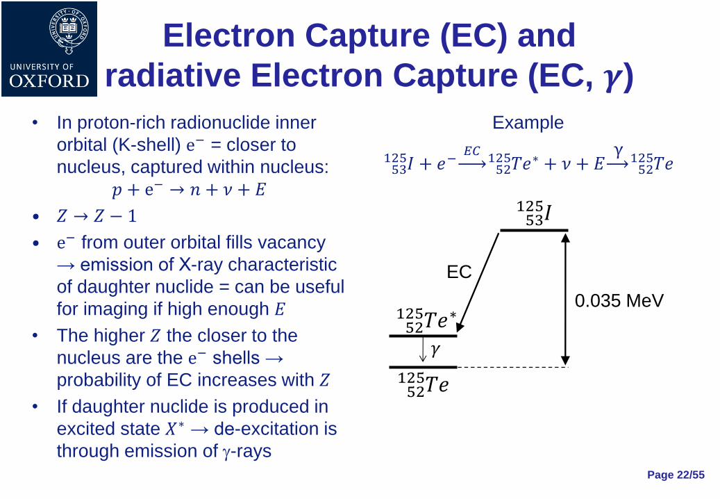
• In proton-rich radionuclide inner
orbital (K-shell) e− = closer to
nucleus, captured within nucleus:
𝑝 + e− → 𝑛 + 𝜈 + 𝐸
• 𝑍 → 𝑍 − 1
• e− from outer orbital fills vacancy
→ emission of X-ray characteristic
of daughter nuclide = can be useful
for imaging if high enough 𝐸
• The higher 𝑍 the closer to the
nucleus are the e− shells →
probability of EC increases with 𝑍
• If daughter nuclide is produced in
excited state 𝑋∗ → de-excitation is
through emission of g-rays
Example
𝐼 + 𝑒− 𝐸𝐶
𝑇𝑒∗ + 𝜈 + 𝐸 γ
𝑇𝑒52125
52125
53125
0.035 MeV
𝐼53125
EC
𝛾
𝑇𝑒52125
𝑇𝑒∗52125

Page 23/55
Feynman diagrams for
𝜷−, 𝜷+ decays and EC
𝑋 𝛽−
𝑌𝑍+1𝐴 + e− + 𝑣 𝑒𝑍
𝐴
𝑋 𝛽+
𝑌𝑍−1𝐴 + e+ + 𝑣𝑒𝑍
𝐴
𝑋 + e− 𝐸𝐶
𝑌𝑍−1𝐴 + 𝑣𝑒𝑍
𝐴
Courtesy Piero Posocco (Imperial College)

𝜷 emitters
Page 24/55
(𝜷−, 𝜸) emitters1
Nuclide Half-life 𝐸𝛽 (MeV) 𝐸𝛾 (keV)
𝐶𝑜60 5.27 yrs 0.096 1173, 1332
𝐼131 8.04 days 0.192 364
𝑋𝑒133 5.24 days 0.101 81
𝐶𝑠137 30.00 yrs 0.173 662
1Only dominant 𝛽− and 𝛾 emissions shown
𝜷+ emitters
Nuclide Half-life (min) 𝐸𝛽+𝑚𝑎𝑥 (MeV) 𝛽+ 𝑟𝑎𝑛𝑔𝑒 in
water (cm)
𝐶11 20.30 0.961 0.103
𝑁13 10.00 1.190 0.132
𝑂15 2.07 1.720 0.201
𝐹18 110.00 0.635 0.064

EC and (EC, 𝜸) radionuclides
Page 25/55
EC radionuclides
Nuclide Half-life 𝑬𝑿−𝒓𝒂𝒚 (keV)
𝐼125 60.1 days ~30
𝑇𝑙201 3.04 days ~70
(EC, 𝜸) radionuclides
Nuclide Half-life 𝑬𝜸 (keV)
𝐶𝑜57 270 days 122, 136
𝐺𝑎67 78.3 h 93, 185
𝐼𝑛111 2.83 days 171, 245
𝐼123 13.2 h 159

Page 26/55
Isomeric transitions (IT)
and metastable states
• Excited state in which daughter
nuclide can be produced called
isomeric state
• Sometimes radiative decays from
isomeric state to ground state are
called isomeric transition
• Isomeric transitions can take from
fractions of seconds (short-lived
states) to many years (long-lived
states)
• Long-lived isomeric states are
called metastable states 𝑋𝑚𝑍𝐴
Example
• 𝑇𝑐𝑚99 most common example of
metastable isotope used in nuclear
medicine
• Decay chain:
𝑀𝑜 𝛽−
99 𝑇𝑐𝑚99 γ
𝑇𝑐99
Half-life for 𝛽− decay = 66 h
Half-life for isomeric transition = 6 h
Internal Conversion (IC)
• 𝛾-ray emitted in isomeric transition interacts with
atomic e− → e− is ejected = conversion electron
• Interaction is usually with K-shell e− as they are
closest to nucleus
• Conversion e− has kinetic energy 𝐸:
𝐸 = 𝐸𝛾 − 𝐸𝑏𝑖𝑛𝑑𝑖𝑛𝑔
• e− from outer shell fills vacancy → characteristic
X-ray emitted
• X-ray emitted can interact with other outer shell e−
→ e− get ejected if 𝐸𝑋−𝑟𝑎𝑦 > 𝐸𝑏𝑖𝑛𝑑𝑖𝑛𝑔 = Auger e−
Page 27/55

Radioactive decay table
Page 28/55
𝑁 (neutrons)
𝑍 (protons)
Stable
EC, 𝛽+
𝛽−
𝛼
P
N
Unknown
Courtesy Piero Posocco (Imperial College)
Production of radionuclides
Ref. 2 – Chapter 5.4.2
• Man-made production:
1. Neutron capture = neutron activation
2. Nuclear fission
3. Charged-particle bombardment
4. Radioactive decay
• Naturally-occurring radionuclides
Page 29/55

Man-made production
technologies
• Nuclear reactors:
1. Neutron capture = nuclear absorption
2. Nuclear fission
• Accelerators:
1. Charged-particle bombardment
• Radionuclide generators:
1. Radioactive decay
Page 30/55

Neutron capture /
nuclear absorption
• Radionuclides produced when neutron absorbed
by atomic nucleus
𝑛𝑒𝑢𝑡𝑟𝑜𝑛 + 𝑛𝑢𝑐𝑙𝑒𝑢𝑠 → 𝑟𝑎𝑑𝑖𝑜𝑛𝑢𝑐𝑙𝑖𝑑𝑒
• For neutron to be captured 𝐸𝑛 needs to be low in
the range 0.03÷100 eV = thermal neutrons
• Radionuclides produced predominantly neutron
rich → decay mainly by 𝛽−
• Production system:
1. Nuclear reactor: creates thermal neutrons
2. Target: placed inside field of thermal neutrons
Page 31/55

Neutron capture reaction chain
• Neutron capture leaves nucleus excited → de-excitation
via emission of 𝛾-ray:
𝑛 + 𝑋 → 𝑋 + 𝛾𝐴+1𝐴
Notation: 𝑋 𝑛, 𝛾 𝑋𝐴+1𝐴
• Radionuclide produced = isotope of target material =
same 𝑍 but 𝐴 + 1 → very difficult to separate → low
purity and activity
• Exception that can be easily separated: 𝐼125 from decay
of 𝑋𝑒125 with half-life 17 h:
𝑋𝑒 𝑛, 𝛾 𝑋𝑒EC 𝑜𝑟 𝛽+
𝐼125125124
Page 32/55

Nuclear fission
• Nuclear fission process:
1. Heavy nuclei ( 𝑇ℎ232 , 𝑈235 , 𝑈237 , 𝑃𝑢239 and others with
𝐴 > 92) are irradiated with thermal neutrons = neutron
bombardment → absorb neutrons → become unstable
2. Unstable nuclei undergo fission = break up into two
lighter nuclei of approximately similar atomic weight
• Fission-produced nuclides have 28 < 𝐴 < 65
• Radionuclides produced predominantly neutron rich
→ decay mainly by 𝛽−
• Fission products can be separated chemically with
high specificity → high quality radiopharmaceuticals Page 33/55

Page 34/55
Nuclear reactor
• Main components:
1. Fuel cells: contain fissionable material
2. Moderator: commonly graphite or 𝐷2𝑂
surrounding fuel cells = slows down
neutrons
3. Control rods: commonly boron
exposing or shielding fuel cells =
heavy neutron absorbers
4. Ports in reactor core: allow samples to
be inserted for irradiation with
neutrons
• Position of fuel cells and control
rods determine rate of chain
reaction
Fission of 𝑈235 or heavily enriched
𝑈235 giving: 1. Fission products
2. Thermal neutrons → can be used to
create radionuclide by neutron capture
Courtesy Piero Posocco (Imperial College)

Reactor-produced
radionuclides Nuclear absorption
Radionuclide Production reaction 𝑬𝜸 (keV) Half-life 𝝈 (Barn)
𝐶𝑟51 𝐶𝑟 𝑛, 𝛾 𝐶𝑟5150 320 27.7 days 15.8
𝐹𝑒59 𝐹𝑒 𝑛, 𝛾 𝐹𝑒5958 1099 44.5 days 1.28
𝑀𝑜99 𝑀𝑜 𝑛, 𝛾 𝑀𝑜9998 740 66.02 h 0.13
𝐼131 𝑇𝑒 𝑛, 𝛾 𝑇𝑒 → 𝐼131131130 364 8.04 days 0.29
Page 35/55
Nuclear fission
Radionuclide 𝑬𝜸 (keV) Half-life Fission yield (%)
𝑀𝑜99 740 66.02 h 6.1
𝐼131 364 8.05 days 2.9
𝑋𝑒133 81 5.27 days 6.5
𝐶𝑠137 662 30 yrs 5.9

Charged-particle bombardment
• Radionuclides produced through interaction of
charged particles (𝐻±, 𝐷+, 𝐻𝑒3 2+, 𝐻𝑒4 2+) with
nuclei of stable atoms
𝑐ℎ𝑎𝑟𝑔𝑒𝑑 𝑝𝑎𝑟𝑡𝑖𝑐𝑙𝑒 + 𝑛𝑢𝑐𝑙𝑒𝑢𝑠 → 𝑟𝑎𝑑𝑖𝑜𝑛𝑢𝑐𝑙𝑖𝑑𝑒
• Radionuclides produced predominantly neutron
deficient → decay by 𝛽+ or EC
• Production system:
1. Accelerator: kinetic 𝐸𝑐ℎ𝑎𝑟𝑔𝑒𝑑 𝑝𝑎𝑟𝑡𝑖𝑐𝑙𝑒 needs to be high
enough to overcome nucleus (+) electrostatic repulsion
2. Target
Page 36/55

Page 37/55
Accelerators
• Two basic types used for medical imaging: 1. Cyclotron → most commonly used and usually located
near hospitals due to radionuclide short half-lives
2. Linear accelerator
Top view
Target
Cyclotron frequency = 𝑓 =𝑞𝐵
2𝜋𝑚
B field

Page 38/55
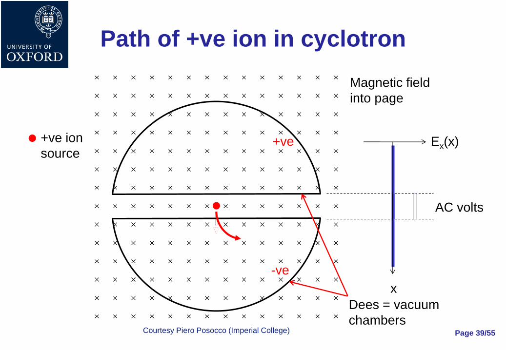
Path of +ve ion in cyclotron
+ve ion
source
Magnetic field
into page
-ve
+ve Ex(x)
x
AC volts
Dees = vacuum
chambers Courtesy Piero Posocco (Imperial College)
Page 39/55
Path of +ve ion in cyclotron
+ve ion
source
Magnetic field
into page
-ve
+ve Ex(x)
x
AC volts
Dees = vacuum
chambers Courtesy Piero Posocco (Imperial College)

Page 40/55
Path of +ve ion in cyclotron
+ve ion
source
Magnetic field
into page
-ve
+ve Ex(x)
x
AC volts
Dees = vacuum
chambers Courtesy Piero Posocco (Imperial College)

Page 41/55
Compact biomedical cyclotron
Power supplies and
Target support unit
Retractable shields
Courtesy Piero Posocco (Imperial College)

Accelerator-produced
radionuclides Radionuclide Principal 𝜸-ray
𝑬𝜸 (keV)1
Half-life Production reaction
𝐶11 511 20.4 min 𝑁 𝑝, 𝛼 𝐶1114
𝑁13 511 9.96 min 𝐶 𝑝, 𝑛 𝑁1313
𝑂15 511 2.07 min 𝑁 𝑝, 𝑛 𝑂1515
𝐹18 511 109.7 min 𝑂 𝑝, 𝑛 𝐹1818
𝐺𝑎67 93, 184, 300 78.3 h 𝑍𝑛 𝑝, 2𝑛 𝐺𝑎6768
𝐼𝑛111 171, 245 67.9 h 𝐶𝑑 𝑝, 2𝑛 𝐼𝑛111112
𝐼120 511 81 min 𝐼 𝑝, 8𝑛 𝑋𝑒120 → 𝐼120127
𝐼123 159 13.2 h 𝑇𝑒 𝑝, 2𝑛 𝐼123112 𝐼 𝑝, 5𝑛 𝑋𝑒123 → 𝐼123127
𝐼124 511 4.2 days 𝑇𝑒 𝑝, 𝑛 𝐼124124
𝑇𝑙201 68÷80.3 73 h 𝑇𝑙 𝑝, 3𝑛 𝑃𝑏201 → 𝑇𝑙201203
Page 42/55
1511 keV 𝛾-rays come from 𝛽+ decay

Radioactive decay
• Radioactive decay of parent radionuclide can lead to:
1. Unstable nuclide = radioactive nuclide = daughter
radionuclide
2. Stable nuclide
• 𝑍 of radionuclide daughter depends on decay type
• Good radionuclides for medical imaging:
1. Daughter is short-lived and has 𝑍 different from parent →
can be easily separated
2. Parent has sufficiently long half-life for production,
processing and shipment
Page 43/55

Radionuclide generator
• The generator:
1. Receives in input radionuclides produced from nuclear
reactors or accelerators
2. Contains:
a) Chemical separation system of daughter radionuclide from parent
radionuclide: chromatographic techniques most common
b) Extraction system
• Main features:
1. Portable → provides local supply of short-lived radionuclides
without a nearby accelerator or nuclear reactor
2. Daughter product replenished continuously by decay of
parent → can be extracted repeatedly
Page 44/55

Generator-produced
radionuclides Parent
P
Parent
half-life
Mode of
decay
P → D
Daughter
D
Daughter
decay
mode
Daughter
half-life
Daughter
𝜸 𝑬𝜸 (keV)
𝑍𝑛62 9.1 h 𝛽+
EC
𝐶𝑢62 𝛽+
EC
9.8 min 511
1173
𝐺𝑒68 280 days EC 𝐺𝑎68 𝛽+
EC
68 min 511
1080
𝑅𝑏81 4.7 h EC 𝐾𝑟81 IT 13 s 190
𝑆𝑟82 25 days EC 𝑅𝑏82 EC
𝛽+
76 s 777
511
𝑀𝑜99 66.02 h 𝛽− 𝑇𝑐𝑚99 IT 6.02 h 140
𝑆𝑛113 115.1 days EC 𝐼𝑛𝑚113 IT 1.66 h 392
𝐻𝑔𝑚195 40 h IT
EC
𝐴𝑢𝑚195 IT 30.6 s 262
Page 45/55

Page 46/55
𝑴𝒐− 𝑻𝒄𝒎𝟗𝟗𝟗𝟗 generator
Ref. 1 – Chapters 3.4 and 3.5
• 𝑇𝑐𝑚99 most common radioisotope used in nuclear medicine:
𝑀𝑜99
𝐻𝑎𝑙𝑓−𝑙𝑖𝑓𝑒=66 ℎ𝑇𝑐𝑚
𝐻𝑎𝑙𝑓−𝑙𝑖𝑓𝑒=6.02 ℎ𝑇𝑐 + 140 keV 𝛾9999
• Also called a Molly or Cow
• Typically used for one week
• 𝑀𝑜99 bound to alumina column as molybdate ion ( 𝑁𝐻4 2𝑀𝑜𝑂4
−)
• 𝑇𝑐𝑚 99 :
– Chemically different → not bound to column → eluted from column with 5÷25 ml saline
– 75÷85% of available 𝑇𝑐𝑚99 extracted

Equation for number of 𝑻𝒄𝒎𝟗𝟗
atoms produced with generator
𝑀𝑜99 𝜆1
𝑇𝑐𝑚 𝜆2
𝑇𝑐9999
𝑁1 𝑁2 𝑁3
• Number 𝑁1 of 𝑀𝑜99 atoms decreases with time from 𝑁0 due to decay:
𝑁1 = 𝑁0𝑒−𝜆1𝑡
• Number 𝑁3 of 𝑇𝑐99 atoms increases with time due to decay of 𝑇𝑐𝑚99
• Number 𝑁2 of 𝑇𝑐𝑚99 atoms has two components = one decreases
with time due to 𝑇𝑐𝑚99 own decay, other increases with time due to
𝑀𝑜99 decay → first order differential equation for 𝑁2: 𝑑𝑁2𝑑𝑡
= 𝜆1𝑁1 − 𝜆2𝑁2 →𝑑𝑁2𝑑𝑡
+ 𝜆2𝑁2 = 𝜆1𝑁1
With boundary condition: 𝑁2 = 0 at 𝑡 = 0
Page 47/55

Solution of first order
differential equation for 𝑵𝟐
• Solution of first order differential equation for 𝑁2 made of two terms:
𝑁2 = 𝐶𝑒−𝜆2𝑡 + 𝐷𝑒−𝜆1𝑡
1. Homogeneous: 𝑁2 = 𝐶𝑒−𝜆2𝑡
2. Particular: 𝑁2 = 𝐷𝑒−𝜆1𝑡
• From boundary condition → 𝐶 = −𝜆1𝑁0
𝜆2−𝜆1
• Solving particular solution for 𝐷 → 𝐷 =𝜆1𝑁0
𝜆2−𝜆1
• Final solution of first order differential equation for 𝑁2:
𝑁2 = −𝜆1𝑁0𝜆2 − 𝜆1
𝑒−𝜆2𝑡 +𝜆1𝑁0𝜆2 − 𝜆1
𝑒−𝜆1𝑡
𝑁2 =𝜆1𝑁0𝜆2 − 𝜆1
𝑒−𝜆1𝑡 − 𝑒−𝜆2𝑡
Page 48/55

Radioactivity 𝑸 of 𝑻𝒄𝒎𝟗𝟗
produced with the generator • Radioactivity 𝑄 of 𝑇𝑐𝑚99 produced with the generator given by:
𝑄 = 𝜆2𝑁2
• Using solution for 𝑁2 the radioactivity 𝑄 is finally given by:
𝑄 = 𝜆2𝜆1𝑁0𝜆2 − 𝜆1
𝑒−𝜆1𝑡 − 𝑒−𝜆2𝑡 =𝜆1𝜆2𝑁0𝜆2 − 𝜆1
𝑒−𝜆1𝑡 − 𝑒−𝜆2𝑡
𝑁0 = number of 𝑀𝑜99 at 𝑡 = 0
𝜆1 = 𝑀𝑜99 decay constant =ln 2
𝜏1/21 =
ln 2
66= 0.0105 h−1
𝜆2 = 𝑇𝑐𝑚99 decay constant =ln 2
𝜏1/22 =
ln 2
6= 0.116 h−1
• Radioactivity proportional to difference of two exponentials =
one governing increase in 𝑇𝑐𝑚99 due to 𝑀𝑜99 decay and other
decrease in 𝑇𝑐𝑚99 due to its decay
Page 49/55

Naturally-occurring
radionuclides • Very long-lived elements
• Mainly very heavy elements
• → Not useful for imaging
Page 50/55
Nuclide Abundance (%) Half-life (yrs)
𝐾40 0.01 1.26 × 10⁹
𝑅𝑏87 27.8 4.88 × 10¹⁰
𝑇ℎ232 100 1.40 × 10¹⁰
𝑈235 0.7 7.04 × 10⁸
𝑈238 99.3 4.46 × 10⁹

Choice of radionuclides
for imaging Ref. 2 – Chapter 3.4.4
• Desirable physical characteristics of radionuclides
for nuclear medicine imaging:
1. Physical half-life:
a. Long enough to allow:
1) Preparation of radiopharmaceuticals
2) Completion of imaging procedures
b. Short enough to ensure dose to patient and staff is minimised
2. Decay via isomeric transition = produces 𝛾 rays with:
a. High photon yield → good counting statistics
b. Suitable 𝐸𝛾
3. Absence of particulate emission (𝛼 or 𝛽 particles) →
no unnecessary dose to patients Page 51/55

Emitted photon energy
• Emitted photon energy critical and chosen as
“compromise” for various reasons:
1. High enough 𝐸𝛾 so that:
a. Photon is able to efficiently escape the body
b. Photopeak is easily separated from scattered radiation
2. Low enough 𝐸𝛾 so that:
a. Detection efficiency is still good
b. Do not penetrate thin collimator septa → thickness of
collimator septa not too big
c. Photons are not too difficult to shield and to handle
Page 52/55

Commonly used radionuclides
for imaging
Page 53/55
Nuclide Decay
mode
Product 𝑬 (keV) Half-life Imaging system Comment
11𝐶 𝛽+ 𝛾 511 20 min PET
13𝑁 𝛽+ 𝛾 511 10 min PET
15𝑂 𝛽+ 𝛾 511 2 min PET
18𝐹 𝛽+ 𝛾 511 110 min PET ~80% of all PET
imaging (FDG)
67𝐺𝑎 EC 𝛾 93, 185, 300 3.3 days g-camera, SPECT
82𝑅𝑏 𝛽+ 𝛾 511 1.25 min PET
𝑇𝑐𝑚99 IT 𝛾 140 6.0 h g-camera, SPECT > 80% of all nuclear
medicine imaging
111𝐼𝑛 EC 𝛾 172, 247 2.8 days g-camera, SPECT Used for longer
term studies
123𝐼 EC 𝛾 159 13 h g-camera, SPECT
201𝑇𝑙 EC X-ray 68÷80 3.0 days g-camera, SPECT

Ref. 2 – Chapter 5.4.5
• Radiopharmaceutical =
radioactive compound
(biomolecule or drug) of suitable
quality to be safely administered to
humans for diagnosis, therapy or research
• Radiopharmaceutical composition:
1. Usually radionuclide + pharmaceutical compound
2. Some exceptions:
a. No associated pharmaceutical compound, for ex. 𝑋𝑒133 gas
b. Pharmaceutical component = counter ion, for ex. 𝑁𝑎𝐼
Radiopharmaceuticals
Page 54/55
Courtesy Piero Posocco (Imperial College)

Radiopharmaceutical
chemistry and biology Ref. 2 – Chapters 5.4.5, 5.4.6 5.4.7 and 5.4.8
• Radiolabelling = “attach” the radionuclide to the
pharmacological compound
• Distribution of radiopharmaceutical within living system
depends on various factors including:
1. 3D structure and size of the molecule
2. Blood flow
• Quality control:
1. Biological purity: toxicity, sterility and apyrogenicity
2. Radiopharmaceutical purity: radionuclide, radiochemical and
chemical purity
Page 55/55
Choice of radiopharmaceuticals
for imaging
• Characteristics of radiopharmaceuticals for nuclear
medicine imaging:
1. Accumulation / rate of uptake or clearance of radiopharmaceutical
should be related to a physiologic, biochemical or molecular
process, target or function
2. No pharmacological or toxicological effects on system / organ
under study → concentration usually subpharmacological
(micromolar to nanomolar)
3. High uptake in target tissue compared with non-target tissue =
specificity → lower required dose + increase image contrast
4. Half-life appropriate for the duration of the study
5. Easily synthesised or labelled
6. Sufficiently long shelf life before and after radiolabelling
7. Be of required pharmaceutical quality
Page 56/55

Page 57/55
Some common
radiopharmaceuticals Compound Nuclide Measurement Example of clinical use
Ammonia 13𝑁 Myocardial perfusion Coronary artery disease
Fluorodeoxyglucose
(FDG)
18𝐹 Glucose metabolism Cancer, neurological disorders
and myocardial diseases
Gallium citrate 67𝐺𝑎 Sequestered in tumours Tumour localization
𝑇𝑐𝑚99 -methylene
diphosphonate (MDP)
𝑇𝑐𝑚99 Bone metabolism Metastatic spread of cancer
Sestamibi, Tetrofosmin 𝑇𝑐𝑚99 Myocardial perfusion Coronary artery disease
MAG3, DTPA 𝑇𝑐𝑚99 Renal function Kidney disease
HMPAO, EDC 𝑇𝑐𝑚99 Cerebral blood flow Neurologic disorders
Labelled white blood
cells
111𝐼𝑛 Sites of infection Detecting inflammation
Sodium Iodide 131𝐼 Thyroid function Thyroid disease


