QNDE 2010, July 21 th , San Diego Imaging of defects with ultrasonic arrays Imaging of defects with ultrasonic arrays in non canonical geometries in non canonical geometries P. Calmon, S. Robert, S. Bannouf, O. Casula, S. Chatillon CEA LIST, Saclay
Transcript
QNDE 2010, July 21th, San Diego
Imaging of defects with ultrasonic arrays Imaging of defects with ultrasonic arrays in non canonical geometriesin non canonical geometries
P. Calmon, S. Robert, S. Bannouf, O. Casula, S. Chat illon
CEA LIST, Saclay
QNDE 2010, July 21th, San Diego
OutlineOutline
� Introduction, context: UT arrays in CIVA
� Full Matrix Capture: 3D imaging, Modelling, Multiple reconstruction
� Imaging of defects through complex surface
� Imaging of defects through complex surface with flexible probes
QNDE 2010, July 21th, San Diego
Context : UT array simulation and processing in CIV A
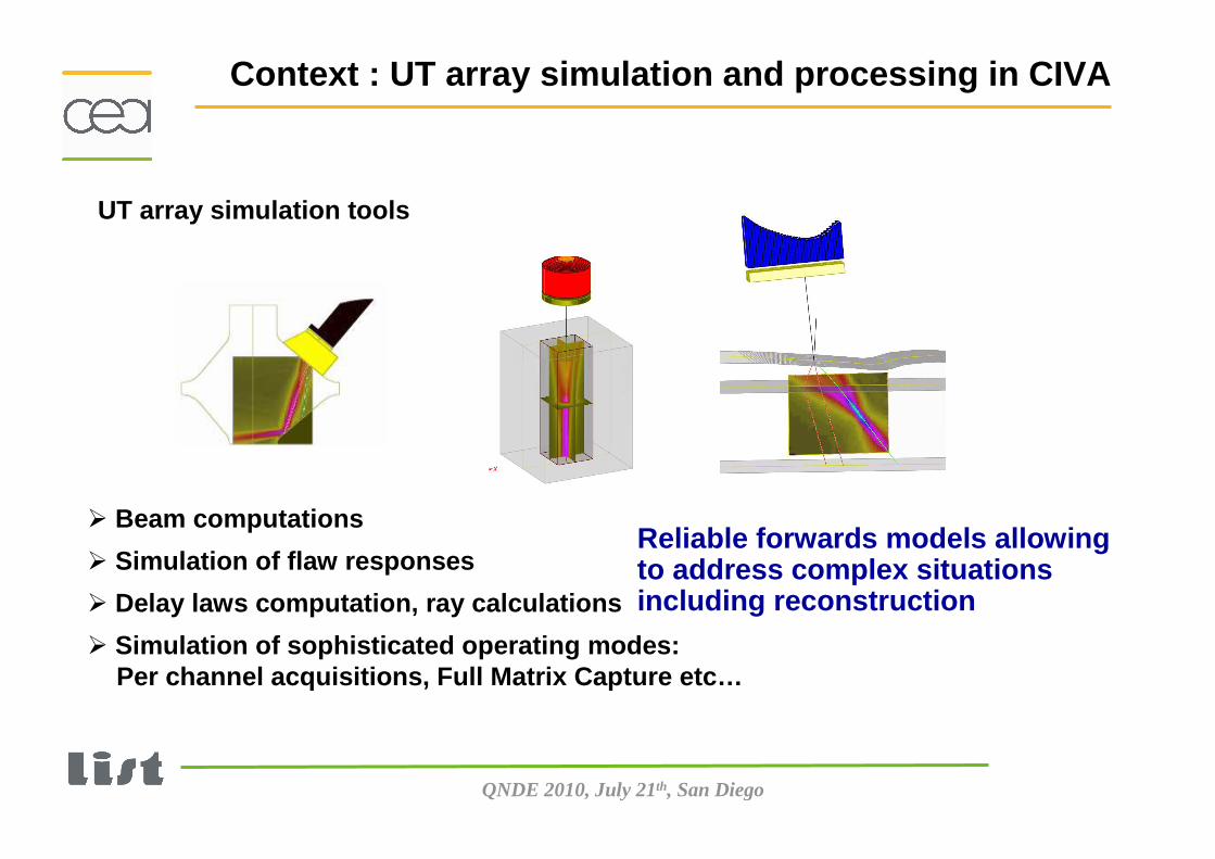
UT array simulation tools
� Beam computations
� Simulation of flaw responses
� Delay laws computation, ray calculations
� Simulation of sophisticated operating modes: Per channel acquisitions, Full Matrix Capture etc…
Reliable forwards models allowingto address complex situations including reconstruction
QNDE 2010, July 21th, San Diego
For every point P in the sampled ROI , computation of the theoretical time of flight (TOF) applying CIVA forward models
Raw data: Elementary signals
ROI
Extraction on the signalsof the amplitudes at this TOF
ΣΣΣΣ
Mapping the estimator:
E(P) = Σn wnP SnPGeneral form:
wnP = 1FTP:
Principle: A posteriori synthetic focusing
Principle of the Total Focussing Method algorithm
� Coherent summation of the received signals for all the points of the imaged region.
� Identical to SAFT for mechanical scanning.
QNDE 2010, July 21th, San Diego
Shot n°1
Application to Full Matrix Capture acquisitions
Tim
e
Elements (Reception)
Tim
e
Elements (Reception)
Tim
e
Elements (Reception)
Tim
e
Elements (Reception)
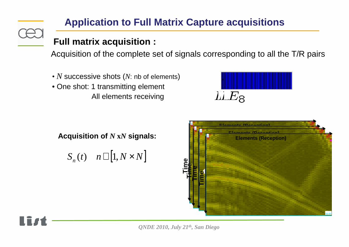
Full matrix acquisition :Acquisition of the complete set of signals corresponding to all the T/R pairs
• N successive shots (N: nb of elements)• One shot: 1 transmitting element
All elements receiving
Acquisition of N xN signals:
[ ]NNntSn ×∈ ,1)(
QNDE 2010, July 21th, San Diego
Flat-bottom holes of various height
Full 3D reconstruction and visualization on simulat ed data
Top view
Volumetric rendering with iso-surfaces
« Full Matrix capture » with a 2D matrix array (11 X 1 1 elements, 2MHz)
QNDE 2010, July 21th, San Diego
Matrix probe 16x8 elements - 5 MHz
H = 30 mm
3 notches 120°
h = 5 mm
Top view
3D Total Focussing Method imaging of 3 notches
QNDE 2010, July 21th, San Diego
OutlineOutline
� Introduction, context: UT arrays in CIVA
� Full Matrix Capture, 3D imaging, Modelling, Multiple reconstruction
� Imaging of defects through complex surface
� Imaging of defects through complex surface with flexible probes
QNDE 2010, July 21th, San Diego
5 mm
30 mm
20 mm
20 mm
5 mm
30 mm
20 mm
20 mm
LL
SimulationExperimental
Calibration: 0db SDH Ø2 mm Traditional imaging Traditional imaging
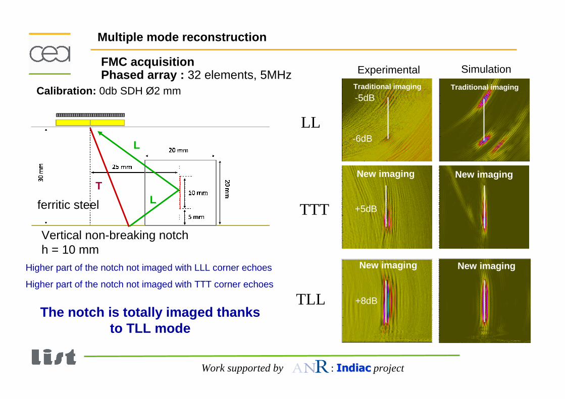
Applications INDIACMultiple mode reconstruction
FMC acquisitionPhased array : 32 elements, 5MHz
Vertical breaking notchh = 5 mm
ferritic steel
Work supported by : IndiacIndiac project
L
L
QNDE 2010, July 21th, San Diego
5 mm
30 mm
20 mm
20 mm
5 mm
30 mm
20 mm
20 mm
LLL
0dB
LL
SimulationExperimental
-3dB
0dB
Calibration: 0db SDH Ø2 mm
LLL
Applications INDIAC
L
L
L
Multiple mode reconstruction
Traditional imaging Traditional imaging
FMC acquisitionPhased array : 32 elements, 5MHz
Vertical breaking notchh = 5 mm
Imaging of the notch thanks to corner echoes
ferritic steel
Work supported by : IndiacIndiac project
New imaging New imaging
QNDE 2010, July 21th, San Diego
5 mm
30 mm
20 mm
20 mm
5 mm
30 mm
20 mm
20 mm
LLL
TTT
+8dB
LL
SimulationExperimental
Calibration: 0db SDH Ø2 mm
LLL
TTT
New imaging New imaging
Applications INDIAC
T
T
T
Multiple mode reconstruction
Traditional imaging Traditional imaging
New imaging New imaging
FMC acquisitionPhased array : 32 elements, 5MHz
Vertical breaking notchh = 5 mm
Imaging of the notch thanks to corner echoes
ferritic steel
Work supported by : IndiacIndiac project
QNDE 2010, July 21th, San Diego
SimulationExperimental
LL
Calibration: 0db SDH Ø2 mm
Nouvelle imagerie Nouvelle imagerie
Applications INDIACMultiple mode reconstruction
Traditional imaging Traditional imaging
FMC acquisitionPhased array : 32 elements, 5MHz
Vertical non-breaking notchh = 10 mm
ferritic steel
Work supported by : IndiacIndiac project
QNDE 2010, July 21th, San Diego
SimulationExperimental
LL
-5dB
-6dB
LLL-1dBL
L
L
Calibration: 0db SDH Ø2 mm
Applications INDIACMultiple mode reconstruction
New imaging New imaging
Traditional imaging Traditional imaging
FMC acquisitionPhased array : 32 elements, 5MHz
Vertical non-breaking notchh = 10 mm
ferritic steel
Work supported by : IndiacIndiac project
Higher part of the notch not imaged with LLL corner echoes
QNDE 2010, July 21th, San Diego
T
T
T
SimulationExperimental
LL
-5dB
-6dB
TTT +5dB
Calibration: 0db SDH Ø2 mm
Applications INDIACMultiple mode reconstruction
New imaging New imaging
Traditional imaging Traditional imaging
FMC acquisitionPhased array : 32 elements, 5MHz
Vertical non-breaking notchh = 10 mm
Higher part of the notch not imaged with TTT corner echoes
ferritic steel
Work supported by : IndiacIndiac project
Higher part of the notch not imaged with LLL corner echoes
QNDE 2010, July 21th, San Diego
SimulationExperimental
LL
-5dB
-6dB
TTT +5dB
Calibration: 0db SDH Ø2 mm
Applications INDIAC
+8dBTLL
L
TL
Multiple mode reconstruction
New imaging New imaging
Traditional imaging Traditional imaging
New imaging New imaging
FMC acquisitionPhased array : 32 elements, 5MHz
Vertical non-breaking notchh = 10 mm
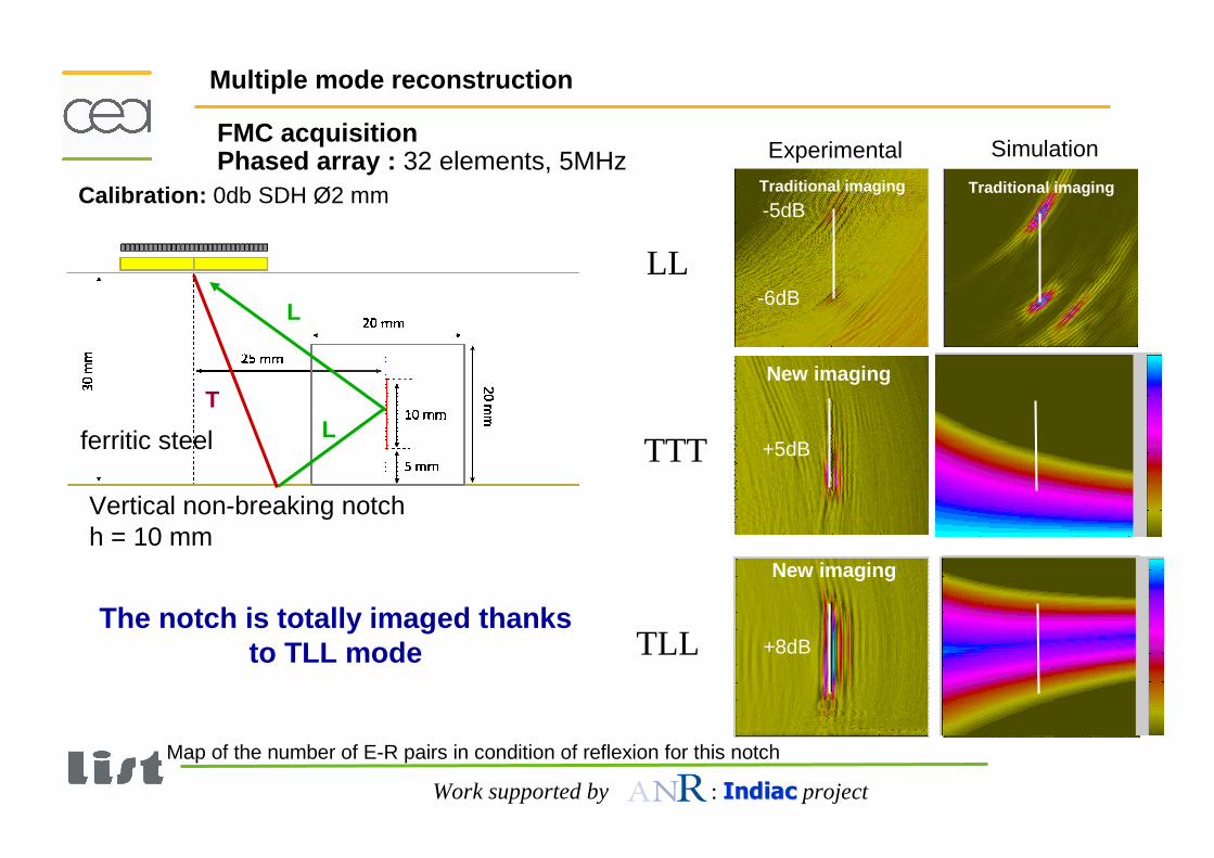
The notch is totally imaged thanks to TLL mode
ferritic steel
Work supported by : IndiacIndiac project
Higher part of the notch not imaged with LLL corner echoes
Higher part of the notch not imaged with TTT corner echoes
QNDE 2010, July 21th, San Diego
SimulationExperimental
LL
-5dB
-6dB
TTT +5dB
Calibration: 0db SDH Ø2 mm
New imaging
Applications INDIAC
+8dBTLL
Multiple mode reconstruction
New imaging
Traditional imaging Traditional imaging
New imaging
FMC acquisitionPhased array : 32 elements, 5MHz
Vertical non-breaking notchh = 10 mm
The notch is totally imaged thanks to TLL mode
Map of the number of E-R pairs in condition of reflexion for this notch
ferritic steel
Work supported by : IndiacIndiac project
New imaging
L
TL
QNDE 2010, July 21th, San Diego
OutlineOutline
� Introduction, context: UT arrays in CIVA
� Full Matrix Capture, 3D imaging, Modelling, Multiple reconstruction
� Imaging of defects through complex surface
� Imaging of defects through complex surface with flexible probes
QNDE 2010, July 21th, San Diego
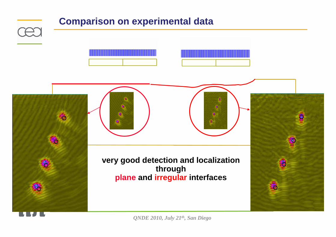
very good detection and localization through
plane and irregular interfaces
Comparison on experimental data
QNDE 2010, July 21th, San Diego
Performance Evaluation by simulationInfluence of unaccuracy on the surface description
With the exact profileh1 = -h2 = 3 mm
- 3dB - 6 dB - 5dB
∆z: 2 mm ∆z: 1 mm∆x: 4 mm
With inexact profiles
∆h1 = + 0.5 mm, ∆h2 = -0.5 mm
- 6dB - 1dB -6dB
∆z: 3 mm ∆z: 4 mm∆x: 4 mm
h1 = -h2 = 2 mm
Ø2mm SDHØ2mm SDH
FMC SimulationLinear array: 64 elts, 2MHz
Lx=100 mm
h2=-3mm
Z(*10)
h1=3mmX
Lx=100 mm
h2=-3mm
Z(*10)
h1=3mmX
Z(*10)
h1=3mmX
Exact profile:
QNDE 2010, July 21th, San Diego
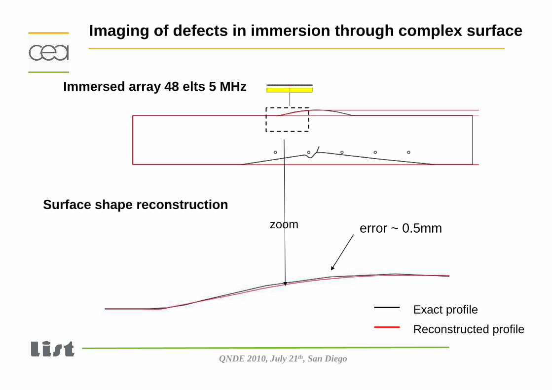
Surface shape reconstruction from immersed array acquisition
Surface
C1 C2
R1R2
x
z
Algorithm:From Time of Flight (TOF)measured on each channel�Profile reconstruction
Functionality implemented in CIVA 10
Export CAD file
From each channel T= R or T≠R
21 ( )
j j j j
j j
x C R R
y R R
′= − ⋅
′= −1
1
j jj
j j
R RR
C C+
+
−′ =
−
Reconstruction
QNDE 2010, July 21th, San Diego
zoom
Exact profile
Reconstructed profile
Surface shape reconstruction
Immersed array 48 elts 5 MHz
Imaging of defects in immersion through complex sur face
error ~ 0.5mm
QNDE 2010, July 21th, San Diego
Imaging of the tilted notch from corner echo
Simulation
TTT
TTL
QNDE 2010, July 21th, San Diego
OutlineOutline
� Introduction, context: UT arrays in CIVA
� Full Matrix Capture, 3D imaging, Modelling, Multiple reconstruction
� Imaging of defects through complex surface
� Imaging of defects through complex surface with flexible probes
QNDE 2010, July 21th, San Diego
Principle of smart flexible phased array
time
Adapted delay law
focus LW45°
Real time algorithm
Reconstruction Profile
Focal point
global error < 2 % time loop : 1ms
Embedded profilometer
MultiX System (M2M) :
Modification of the settings in real time by embedded processorsReal time Delay law algorithm
QNDE 2010, July 21th, San Diego
14 mm
40 mm27 mm
scanning
Beam steering : LW45 - depth 40mm
Aperture of 24 elements (33 x 17 mm²)
Smart flexible phased array on realistic 2D surface
Focal point
Reconstructed profile
QNDE 2010, July 21th, San Diego
scanning
G3
G3 – Planar surface G7 – Irregular surface-4.0dB
-3.5dB
-2.0dB
0dB (ref)
40mm
0°55°
~4.5mm2 sets of 4 SDH (2mm-diameter) located under:- a flat surface (ref.), - an irregular profile.
Experimental detection of SDH on realistic 2D surfac e
Accurate detection (SNR, Bandwidth)Low sensitivity to surface irregularities (-3.5dB / 5mm)
QNDE 2010, July 21th, San Diego
scanning
LW0° LW0°LW0° 35mm
scanning
Real time reconstruction of external and internal compl ex 2D geometries
Real time visualisation in the M2M software
Profile reconstruction
- Real Time Reconstruction Functionality with the 2D flexible phased-array transducer
���� External surface reconstruction thanks to the embed ded profilometer (error<0.5mm)
���� Internal surface reconstruction with the backwall e cho : Very close to the theory (average error~0.4mm)
- Profile data storage and export to a CAD file form at
The notch is imaged thanks to LLT and TLT mode through complex
surface and backwall
Multiple mode reconstruction
QNDE 2010, July 21th, San Diego
Imaging of the tilted notch from corner echo
TTT
TTLRSB = 16 dB
SimulationExperiment
RSB = 14 dB
QNDE 2010, July 21th, San Diego
Matrix arrayElements moulded in a flexible resin
Embedded profilometer
84 elts, 3 MHz
Flat bottom hole (Ø3 mm) at the junction cone/cylinder
3D Imaging: Example of nozzle geometry
Ø 3mm L=10mm depth 40mm
QNDE 2010, July 21th, San Diego
Backwall echo
FBH
Backwall echo
Angular scanning
Scanning
Tim
e
Acquisition
TrajectoryTrajectory : : Scanning along the cone-cylinder junction
AcquisitionAcquisition
3D reconstruction3D reconstruction
3D sectorial scan imaging of the FBH under the juncti on
QNDE 2010, July 21th, San Diego
L-E imageL-H image
E-H image
3D FTP imaging of the FBH under the junction
3D view
L-E Echodynamic
Dynamique: 13 dBRSB 13 dB
QNDE 2010, July 21th, San Diego
SummarySummary
� The reconstruction algorithm Total Focusing Method implemented in CIVA is coupled to forwards models allowing to compute theoretical times of flights in non canonical situations..
� The exploitation of multiple modes offers the means of imaging crack-type defects. Very promising results have been obtained on both simulated and experimental data.
� Comparisons of different acquisition/reconstruction techniques on various cases of interest.
� Optimization of algorithms and strategies for reducing processing time.


![Rational Canonical Formbuzzard.ups.edu/...spring...canonical-form-present.pdfIntroductionk[x]-modulesMatrix Representation of Cyclic SubmodulesThe Decomposition TheoremRational Canonical](https://static.documents.pub/doc/80x56/6021fbf8c9c62f5c255e87f1/rational-canonical-introductionkx-modulesmatrix-representation-of-cyclic-submodulesthe.jpg)


