2/10/2014 1 2/10/2014 1 Intelligent Motor Control Industrial Networks Designs and Considerations David C. Mazur, P.Eng., Ph.D. & Gregory S. Wilcox 2/10/2014 2 Speakers David C. Mazur, P.Eng., Ph.D. Global Technical Consultant David received his B.S. EE degree summa cum laude and first in his class from Virginia Polytechnic Institute and State University, Blacksburg, VA in 2011. David graduated with his M.S. EE degree in 2012 for his work based on rotor angle measurement of synchronous machines from Virginia Polytechnic Institute and State University. He graduated with his Ph.D. in Mining Engineering in September 2013 for his work with the IEC 61850 standard. He is an active member of the IEEE IAS and serves as working group chair for the Communication-Based Protection of Industrial Applications Working Group. He also serves as a member of the Mining Industry Committee (MIC) as well as the Industrial and Commercial Power Systems Committee (I&CPS). David is also an active voting member of the IEEE Standards Association (SA). Gregory Wilcox Development Manager for Reference Architectures Gregory leads a multi-company effort to establish tested and validated design guidelines that helps to reduce risk, simplify design and speed deployment of large-scale industrial automation network infrastructures. As a major contributor to the Cisco and Rockwell Automation Alliance, Gregory has advanced the adoption of convergence between industrial automation technology (IAT) and information technology (IT). Gregory has been designing and implementing industrial automation network solutions for the past 28 years, with 24 of those years at Rockwell Automation, holding roles of increasing responsibility such as Application Engineer and Solution Architect, resulting in extensive experience in developing control and information solutions for industrial applications. Prior to joining Rockwell Automation, Gregory worked in the defense industry developing industrial automation and control system solutions for both discrete and process applications.
Transcript
2/10/2014
1
2/10/20141
Intelligent Motor Control
Industrial Networks Designs and Considerations
David C. Mazur, P.Eng., Ph.D. & Gregory S. Wilcox
2/10/20142
Speakers
David C. Mazur, P.Eng., Ph.D.Global Technical Consultant
David received his B.S. EE degree summa cum laude and first in his class from Virginia Polytechnic Institute
and State University, Blacksburg, VA in 2011. David graduated with his M.S. EE degree in 2012 for his work
based on rotor angle measurement of synchronous machines from Virginia Polytechnic Institute and State
University. He graduated with his Ph.D. in Mining Engineering in September 2013 for his work with the IEC
61850 standard. He is an active member of the IEEE IAS and serves as working group chair for the
Communication-Based Protection of Industrial Applications Working Group. He also serves as a member of
the Mining Industry Committee (MIC) as well as the Industrial and Commercial Power Systems Committee
(I&CPS). David is also an active voting member of the IEEE Standards Association (SA).
Gregory WilcoxDevelopment Manager for Reference Architectures
Gregory leads a multi-company effort to establish tested and validated design guidelines that helps to
reduce risk, simplify design and speed deployment of large-scale industrial automation network
infrastructures. As a major contributor to the Cisco and Rockwell Automation Alliance, Gregory has
advanced the adoption of convergence between industrial automation technology (IAT) and information
technology (IT). Gregory has been designing and implementing industrial automation network solutions
for the past 28 years, with 24 of those years at Rockwell Automation, holding roles of increasing
responsibility such as Application Engineer and Solution Architect, resulting in extensive experience in
developing control and information solutions for industrial applications. Prior to joining Rockwell
Automation, Gregory worked in the defense industry developing industrial automation and control
system solutions for both discrete and process applications.
2/10/2014
2
Agenda
3 2/10/2014
Agenda
4 2/10/2014
2/10/2014
3
Industrial Networks Trends
Open networks are in demand–Broad availability of products, applications and vendor support for Industrial Automation and Control System (IACS)
–Network standards for coexistence and interoperability of industrial automation devices
Convergence of network technologies–Reduce the number of disparate networks in an operation and create seamless information sharing throughout the plant-wide / site-wide architecture
–Use of common network design, deployment and troubleshooting tools across the plant-wide / site-wide architecture; avoid special tools for each application
5 2/10/2014
Industrial Networks Trends
Better asset utilization to support lean initiatives–Common network infrastructure assets, while accounting for environmental requirements
–Reduce training, support, and inventory for different networking technologies
Future-ready – maximizing investments and minimizing risks–Support new technologies and features without a network forklift upgrade
6 2/10/2014
2/10/2014
4
Industrial Applications Convergence
7 2/10/2014
Information
I/ODriveControl
SafetyApplications
ProcessPowerControl
Multi-discipline Industrial Network Convergence
HighAvailability
EnergyManagement
Controller
Drive Network
Safety Network
I/O Network
Plant/Site Network
Disparate Network Technology
Safety I/O
Single IndustrialNetwork Technology
Camera
Controller
VFDDrive
HMI
I/OPlant/Site
Instrumentation
Industrial Network Technology should service…
8 2/10/2014
IT Network Engineer
� Use standard Ethernet and TCP/IP
� Utilize common network infrastructure assets & tools
System Integrator
� Enable seamless plant-wide / site-wide information sharing
� Converge industrial and non-industrial traffic
Equipment Builder� Enable convergence-
ready solutions� Use a single multi-
discipline control and information platform
Control System Engineer
� Enable future-ready, high performance
� Use an established, widely accepted network technology supported by leading industry vendors
2/10/2014
5
Network Technology Convergence
9 2/10/2014
Process ControlDiscrete ControlInformation TechnologyIntelligent Motor Control
Industrial Network Design Methodology
10 2/10/2014
10
Understand application and functional requirements– Devices to be connected – industrial and non-industrial
– Data requirements for availability, integrity and confidentiality
– Communication patterns, topology and resiliency requirements
– Types of traffic – information, control, safety, time synchronization,
drive control, voice, video
Develop a logical framework (roadmap)– Migrate from flat networks to structured and hardened networks
– Define zones and segmentation, place applications and devices
in the logical framework based on requirements
Develop a physical framework to align
with and support the logical framework
Deploy a Defense-in-Depth Security Model
Reduce risk, simplify design, and speed deployment:– Use information technology (IT) standards
– Utilize reference models and reference architectures
Avoiding
Network Sprawl!!
MANAGE /
MONITOR
IMPLEMENT
AUDIT DESIGN/PLAN
ASSESS
Enabling OEM
Convergence-Ready
Solutions
Because Network
Infrastructure Matters
2/10/2014
6
Cabling Benefits
UL / cUL listed for use with high voltage power cables
− 600V cable designed to support high voltage applications
− UL rated for use in Power Limited Trays
Provides reliable network connection in harsh conditions
− Protected from noise, chemicals, thermal and mechanical issues for the harshest possible industrial environments (M3I3C3E3 rated)
− Foil and braided shield for maximum noise immunity
− Wide thermal operational range (-20C … 80C)
Cat 5e cable enables high speed data rate
− More data can be transferred in a shorter period of time
� Copper cabling standard but fiber can be used for longer runs
� +/- 2KV, 40A surge repeatedly applied to the network cable
� IEC 61000-4-5
Lightning Strike
� +/- 1KV high voltage burst applied to the network cable
� IEC 61000-4-4
Industrial Noise
� +/- 8KV ESD event at 12 locations on the MCC and network cable
� IEC 61000-4-2
Static Discharge
� 150kHz … 80MHz interference applied to the network cable
� IEC 61000-4-6
Radio Frequency Interference
No Communication Failures! No Dropped Packets!Less Down Time!
Embedded Systems – Rugged Industrial Design
2/10/2014
7
Network Design Considerations
13 2/10/2014
Recommendations and guidance to help reduce Latency and Jitter, to help increase data Availability, Integrity and Confidentiality, and to help design and deploy a Scalable, Robust, Secure and Future-Ready network infrastructure
– Higher Latency� Use case examples – HMI and Data Collection
WAN
PSTN
Remote Site Plant Site
2/10/2014
16
Benefits of Ethernet/IP
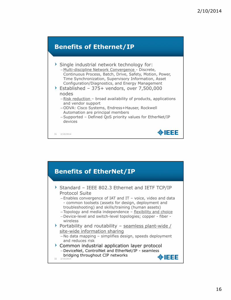
Single industrial network technology for:–Multi-discipline Network Convergence - Discrete, Continuous Process, Batch, Drive, Safety, Motion, Power, Time Synchronization, Supervisory Information, Asset Configuration/Diagnostics, and Energy Management
Established – 375+ vendors, over 7,500,000 nodes–Risk reduction – broad availability of products, applications and vendor support
–ODVA: Cisco Systems, Endress+Hauser, Rockwell Automation are principal members
–Supported – Defined QoS priority values for EtherNet/IP devices
31 2/10/2014
Benefits of EtherNet/IP
Standard – IEEE 802.3 Ethernet and IETF TCP/IP Protocol Suite –Enables convergence of IAT and IT – voice, video and data - common toolsets (assets for design, deployment and troubleshooting) and skills/training (human assets)
–Topology and media independence – flexibility and choice–Device-level and switch-level topologies; copper - fiber -wireless
Portability and routability – seamless plant-wide / site-wide information sharing–No data mapping – simplifies design, speeds deployment and reduces risk
Common industrial application layer protocol–DeviceNet, ControlNet and EtherNet/IP - seamless bridging throughout CIP networks
32 2/10/2014
2/10/2014
17
Automatic Device Configuration
33
EtherNet/IP
3:00 AM
IP AddressFlashConfiguration
Saves the End-User time / money by reducing down-time
2/10/201434
Intelligent Motor Control
Real Time Network Design and Segmentation
David C. Mazur, P.Eng., Ph.D. & Gregory S. Wilcox
2/10/2014
18
Application Requirements
35 2/10/2014
3
Source: ARC Advisory Group
� What is real-time?
� Application dependent ….. only you can define what this means for your application.
Function
Information Integration,
Slower Process Automation
Time-criticalDiscrete Automation
Motion Control
CommunicationTechnology
.Net, DCOM, TCP/IP Industrial Protocols - CIPHardware and Software
solutions, e.g. CIP Motion, PTP
Period 10 ms to 1000 ms 1 ms to 100 ms 100 µs to 10 ms
IndustriesOil & gas, chemicals,
energy, water
Auto, food & beverage, semiconductor,
metals, pharmaceuticalSubset of discrete automation
Material handling, filling, labeling, palletizing, packaging
Printing presses, wire drawing, web making, pick & place
Network Technology Convergence
36 2/10/2014
Theoretical Ethernet @ 100 Mbps
– Short frame with 64 bytes (1 bit – 10ns)
≈ 148,000 frames/second
– Long frames with 1518 bytes
≈ 8,000 frames/second
Theoretical EtherNet/IP @ 100 Mbps
– Typical I/O frame size (64 byte + 36 byte I/O
data) ≈ 104,000 frames/second
– Maximum I/O frame size (64 byte + 511 byte
I/O data) ≈ 21,000 frames/second
� Normal CIP Forward_Open
I/O Scanner exchanges 36 bytes of I/O
data with 10 I/O adapters every 1 ms
– The I/O Scanner must be able to:
� Consume 10,000 frames/second
� Product 10,000 frames/second
Design considerations you should consider
Performance of Scanner
– Maximum # of Adapters (CIP
Connections)
– Minimum RPI (how fast)
– Maximum I/O Data Size per RPI
Performance of Adapters
– Minimum RPI (how fast)
– Maximum I/O Data Size per RPI
Network Infrastructure Latency and
Jitter
Speed / Duplex
Physical Environment – e.g. EMI
Interference
This represents about 10% of the total network bandwidth
2/10/2014
19
Segmentation
37 2/10/2014
3
Structured and HardenedIACS Network Infrastructure
Flat and OpenIACS Network Infrastructure
Flat and OpenIACS Network Infrastructure
Segmentation
– Smaller modular building blocks to help 1) minimize network sprawland 2) build scalable, robust and future-ready network infrastructure� Smaller fault domains (e.g. Layer 2 loops)� Smaller broadcast domains� Smaller domains of trust (security)
Multiple techniques to create smaller network building blocks (Layer 2 domains)– Structure and hierarchy
� Logical model – geographical and functional organization of IACS devices� Campus network model - multi-tier switch model – Layer 2 and Layer 3� Logical framework
– Segmentation� Multiple network interface cards (NICs) – e.g. CIP bridge� Network Address Translation (NAT) appliance� Virtual Local Area Networks (VLANs)� VLANs with NAT� Integrated Services Router
38 2/10/2014
2/10/2014
20
Structure and Hierarchy
39 2/10/2014
3
Logical ModelIndustrial Automation and Control System (IACS)
Converged Multi-discipline Industrial Network
Structure and Hierarchy – Logical Framework
40 2/10/2014
4
• The Cell/Area zone is a Layer 2 network for a functional area (plant-wide or site-wide) Key network considerations include:� Structure and hierarchy using smaller Layer 2 building blocks� Logical segmentation for traffic management and policy enforcement (e.g. QoS, Security) to
accommodate time-sensitive applications
Levels 0–2
Phone
Controller
SafetyController
Camera
Safety I/O
Instrumentation
HMI
Cell/Area Zones
Rockwell AutomationStratix 5700/8000
Layer 2 Access Switch
Catalyst 3750 StackWiseSwitch Stack
Media & Connector
sCell/Area Zone #1Redundant Star TopologyFlex Links Resiliency
Cell/Area Zone #2Ring TopologyResilient Ethernet Protocol (REP)
Cell/Area Zone #3Bus/Star Topology
MCC
Layer 3 Distributi
on SwitchLayer 2
Access Switch
Soft Starter
Level 2 HMI
Level 0 Drive
I/O
Layer 3Building Block
Layer 2Building Block
Level 1 Controller
Layer 2Building Block
ServoDrive
Layer 2Building Block
2/10/2014
21
Islands of Automation with Isolated Networks
41 2/10/2014
4
� Islands of Automation
VFDDrive
HMI
I/O I/O
VFDDrive
HMI
I/O
I/O
Instrumentation
Controller
VFDDriveHMI
I/O
I/O
ServoDrive
Sneakernet
Controller ServoDrive
Controller
Segmentation– Multiple Network Interface Cards
42 2/10/2014
4
� Benefits� Clear network ownership demarcation line
� Challenges� Limited visibility to control network devices for
asset management
� Limited future-ready capability
� Smaller PACs may not support
� Benefits� Plant-wide information sharing for data
collection and asset management
� Future-ready
� Challenges� Blurred network ownership demarcation line
� Isolated networks - two NICs for physical network segmentation
� Converged networks – logical segmentation
Converged
Network
Shared Layer 2 Network
VLAN 102
Control Network
Levels 0-2
Plant Network
Level 3
Layer 2 Network
Layer 2 Network
Control Network
Levels 0-2
Plant Network
Level 3
2/10/2014
22
Segmentation
43 2/10/2014
4
� Benefits� Clear network ownership demarcation line
� Challenges� Limited visibility to control network devices for
asset management
� Limited future-ready capability
� Smaller PACs may not support
� Benefits� Plant-wide information sharing for data
collection and asset management
� Future-ready
� Challenges� Blurred network ownership demarcation line
� Converged networks - logical segmentation - two NICs for scalability, performance, capacity and flexibility
Layer 2 Network
Segmented (using
VLANs), Layer 2 Network
VLAN 103
VLAN 102
Converged
Network
Control Network
Levels 0-2
Plant Network
Level 3
Control Network
Levels 0-2
Layer 2 Network
Plant Network
Level 3
� Isolated networks - two NICs for physical network segmentation
• Reusable IP addresses / subnets• Clear demarcation line of network ownership• Enhanced security features
• More difficult to design, deploy and manage -manual entry and management of IP address translations
• No Link Resiliency (redundant path topologies)
VLANs Only SegmentationStratix 5700
• Scalable and future-ready• Smaller Layer 2 domains (broadcast and
fault)• Smaller domains of trust (management of
security policies)• Link Resiliency (redundant path topologies)
• Layer 3 switch or router is required to forward (route) information between VLANs
• Every node requires a unique IP address• Blurred demarcation line of network ownership
VLAN Segmentation with NATStratix 5700
• Scalable and future-ready• Smaller Layer 2 domains (broadcast and
fault)• Smaller domains of trust (management of
security policies)• Reusable IP addresses / subnets• Link Resiliency (redundant path topologies)
• Layer 3 switch or router is required to forward (route) information between VLANs
• More difficult to design, deploy and manage -manual entry and management of IP address translations
• Blurred demarcation line of network ownership
Industrial Traffic Prioritization
56 2/10/2014
Not all traffic is
created equal!
Control
(e.g., CIP)Video
Data
(Best Effort)Voice
Bandwidth Low to Moderate Moderate to High Moderate to High Low to Moderate
Random Drop
SensitivityHigh Low High Low
Latency
SensitivityHigh High Low High
Jitter Sensitivity High High Low High
Plant-wide / site-wide networks must prioritize industrial automation and control system (IACS) traffic (CIP) over other traffic types (HTTP, SMTP, etc.) to ensure deterministic data flows with low latency and low jitter
Different industrial traffic types (HMI, I/O, Safety, Motion) have different requirements for latency, packet loss and jitter
2/10/2014
29
Quality of Service (QoS)
57 2/10/2014
QoS helps mitigate the following network issues:
– End-to-end delay
� Fixed delay – latency
� Variable delay – jitter
– Bandwidth capacity issues
– Packet loss
QoS design considerations:
– QoS prioritizes traffic into different service levels
– Provides preferential forwarding treatment to some data traffic, at the expense of others
– Allows for predictable service for different applications and traffic types
Quality of Service (QoS)
58 2/10/2014
QoS classification based on Layer attributes:
– Layer 2 Destination MAC Address
– Layer 2 EtherType
– Layer 3 Source / Destination IP Address
– Layer 4 TCP / UDP Source or Destination Port Number
ODVA EtherNet/IP QoS Specification
– Layer 2 … Class of Service (CoS) … 802.1Q/p
– Layer 3 … type of service (ToS) … DiffServ Code Point (DSCP)
ClassificationPolicing/Metering
Marking
Queue/Schedule
Congestion Control
INGRESS ACTIONS EGRESS ACTIONS
Distinguish Traffic by examining Layer 2/3/4 labels and QoS fields.QoS changed depending on trust state at port.
Ensure conformanceto a specified rate
DSCP-CoS or CoS-DSCP mapping
4 queues/port withPriority scheduling
2/10/2014
30
QoS ODVA and DSCP and CoSPriority values
59 2/10/2014
Traffic TypeCIP Priority DSCP
Layer 3
CoS
Layer 2
CIP Traffic Usage
PTP event
(IEEE 1588)
n/a 59 7 PTP event messages, used
by CIP Sync
PTP General
(IEEE 1588)
n/a 47 5 PTP management
messages, used by CIP Sync
CIP class 0 / 1 Urgent (3) 55 6 CIP Motion
Scheduled (2) 47 5 Safety I/O
I/O
High (1) 43 5 I/O
Low (0) 31 3 No recommendations at
present
CIP UCMM
CIP class 3
All 27 3 CIP messaging
Prioritization
60 2/10/2014
PTP-Event
Critical Data
Video
Call Signaling
Best Effort
Voice
Bulk Data
Network Control
ScavengerCritical Data
Video
Call Signaling
Best Effort
Voice
Bulk Data
Network Control
Scavenger
CIP Explicit
Messaging
CIP Motion
PTP Management,
Safety I/O
& I/O
Typical Enterprise QoSCell/Area Zone QoS Priority
Queue, Queue 1
Output Queue 3
Output Queue 4
Output Queue 2
Output Queue 2
Priority Queue,
Queue 1
Output Queue 3
Output Queue 4
Note: Due to queue characteristics of the Stratix
5700/8000/8300, the queue order of priority is different
than general enterprise switch.
2/10/2014
31
QoS Design Considerations
61 2/10/2014
QoS trust boundary moving from switch access ports to QoS-capable CIP devices
For existing CIP devices, marking at the switch access port is based on port number
– CIP I/O UDP 2222
– CIP Explicit TCP 44818
– Established through Stratix Express Setup
Prioritize traffic to reduce latency and jitter for CIP I/O traffic
– Prioritized traffic delivery for CIP Syncand CIP Motion
– Minimize impacts by DDoS attacks
Deploy QoS throughout the IACS networkto take better advantage of QoS features
No Trust + Policing + CoS/DSCPMarking + Queuing
Trusted DSCP + CoSMarking + Queuing
Trusted DSCP + CoSMarking + Queuing
GigabitEthernet
FastEthernet
I/O
HMI
Controllers
Drive
ServoDrive
CIP Motionor QoS ready
device
Device w/out QoS marking
support
QoS Concluding Thoughts
Plant-wide / site-wide networks must prioritize industrial automation and control system (IACS) traffic (CIP) over other traffic types (HTTP, SMTP, etc.) to ensure deterministic data flows with low latency and low jitter
Quality of Service does not increase bandwidth.
– QoS gives preferential treatment to EtherNet/IP IACS network traffic at the expense of other network traffic types
QoS is integrated into the Stratix 5700/8000/8300 switch configurations
– The Stratix 5700/8000/8300 recognizes or ‘trusts’ QoS capable devices and prioritizes CIP traffic as it exits from the switch
Deploy QoS consistently throughout the EtherNet/IP IACS Network
– The more IACS devices that implement QoS, the better that the network infrastructure devices (switches, routers) can take advantage of QoSfeatures
Overall in Network TCO and Performance Best OK Worst
RedundantStarFlex Links
RingResilient Ethernet Protocol (REP)
Star/BusLinear
HMI
CiscoCatalyst 2955
Cell/Area Zone
Cisco Catalyst3750 StackWise
Switch Stack
Controllers,Drives, and Distributed I/O
HMI
Cell/Area Zone
Controllers
Controllers, Drives, and Distributed I/O
Cell/Area ZoneControllers, Drives, and Distributed I/O
HMI
Controllers
Cell/Area Zone
HMI
Controller
Cisco Catalyst3750 StackWise
Switch Stack
Cisco Catalyst3750 StackWise
Switch Stack
Layer 2– Loop Avoidance
66 2/10/2014
� Redundant paths create a switching (bridging) loop
�Without proper configuration, a loop will lead to a broadcast storm, flooding the network, which will consume available bandwidth, and take down a Layer 2 switched (bridged) network
� Layer 2 Ethernet frames do not have a time-to-live (TTL)
� A Layer 2 frame can loop forever
Rockwell Automation
Stratix 5700/8000
Managed Industrial
Layer 2 Access Switch
Rockwell Automation
ControlLogix
Programmable Automation Controller
2/10/2014
34
Layer 2 Loop Avoidance
67 2/10/2014
A Layer 2 resiliency protocol maintains redundant paths while avoiding switching (bridging) loop
Forwarding
Blocking
Layer 2 Loop Avoidance
68 2/10/2014
Link Failure
Blocking
� Network convergence (healing, recovery, etc.) must occur before the
Industrial Automation and Control System (IACS) application is
impacted
2/10/2014
35
Network Convergence
Network convergence (healing, recovery, etc.) time – is a measure of how long it takes to detect a fault, find an alternate path, then start forwarding network traffic across that alternate path.
– MAC tables must be relearned
– Multicast on uplinks must be relearned
During the network convergence time, some portion of the traffic is dropped by the network because interconnectivity does not exist.
If the convergence time is longer than the Logix controller connection timeout, the IACS EtherNet/IP devices on the affected portion of the network may stop operating and may affect the industrial automation application.
69 2/10/2014
Example Layer 2 Loop Avoidance
70 2/10/2014
Network convergence must occur quickly enough to avoid a Logix Controller connection timeout:
– Message (MSG) instruction - Explicit, CIP Class 3