21
IMIA 1997 Stress Corrosion Cracking • Ill Engineering Insurance Presented by: H. Gewalt Gerling Dr . U. Minkus Gerling Mr. Wollmann Allianz IMIA 6 - 56 (97) E
IMIA 1997
Stress Corrosion Cracking
• Ill
Engineering Insurance
Presented by:
H. Gewalt Gerling Dr. U. Minkus Gerling Mr. Wollmann Allianz
IMIA 6 - 56 (97) E

.-
2 ~6-56(97)E
1 Introduction:
General description I example:
Stress corrosion cracking is defined as the failure of metals under the combined action of a corrosive environment and tensile stresses. The insidious haz.ard of stress corrosion cracking is its unexpected appearance. For example a component can work for a long time under normal operation conditions and considerably high loads within the acceptable stress range without showing any unusual behaviour. As expected for this passive material there are no signs of uniform or pitting corrosion. Just a slight shift in the surrounding atmosphere though, for example through another application or due to changed operational conditions, can lead to stress corrosion cracking and to rapid failure. With a decreased load this component can resist the same corrosive atmosphere for ever. In other cases normally reliable components, now manufactured by a new process suddenly break - they prove susceptible to stress corrosion cracking due to the fact that the new production process creates residual tensile stresses on the surface (e.g. cold forming, welding). The result is that the combination of external and residual stresses exceed the critical amount for this specific atmosphere.
The initiated crack on the surface propagates continuously through the whole cross-section of the component, depending on the load cycles and the corrosive atmosphere. If the remaining section cannot withstand any longer the steadily increasing stress, a forced fracture will occur. This final fracture usually occurs spontaneously and unexpectedly without any prior evidence or warning. The damage in consequence can be considerable .
Fresh stress corrosion cracks cannot be recognised by visual tests. There are normally no signs of any other form of corrosion (pits or corrosion products - rust). The wide range of non-destructive tests offers various procedures for detecting cracks, but in practice these examinations are only carried out for critical sections of essential components. Many ,,non essential" components are not or only with prohibitively expensive additional efforts accessible for in depth examinations. As a result and for economical reasons ,,uncritical" sections are not normally subject to a complete NTD during maintenance overhauls.
There are two other types of failure very closely related to stress corrosion cracking and its mechanism, being the corrosion fatigue and the strain induced corrosion cracking: Especially the boundary between stress corrosion cracking and corrosion fatigue is not clearly defined: there is a large 'grey area' . Due to their importance two separate sections of this paper are devoted to the issues corrosion fatigue and strain induced corrosion cracki~g.
2 Stress corrosion cracking:
2.1 Classification:
Genarally the type of load is accepted as a main criteria for the classification of cracks and fractures. The three typical categories of cracks are (See Attachment; Page 2):

3 IMIA 6 - 56 (97) E
a) cracks due to mechanical load, b) cracks due to thermal load and c) cracks due to corrosion.
In most cases these loads occur in combination.
Corrosion induced cracks and fractures furthermore fall into two categories depending on whether or not mechanical loading is involved. Cracks formed without any influence of mechanical loads usually show an intergranular corrosion. As indicated with the expression usually, intergranular corrosion cracks can sometimes occur though also under the influence of mechanical load.
The hydrogen-induced cracking and hydrogen induced stress corrosion cracking is not dealt with in this paper.
2.2 Prerequisites:
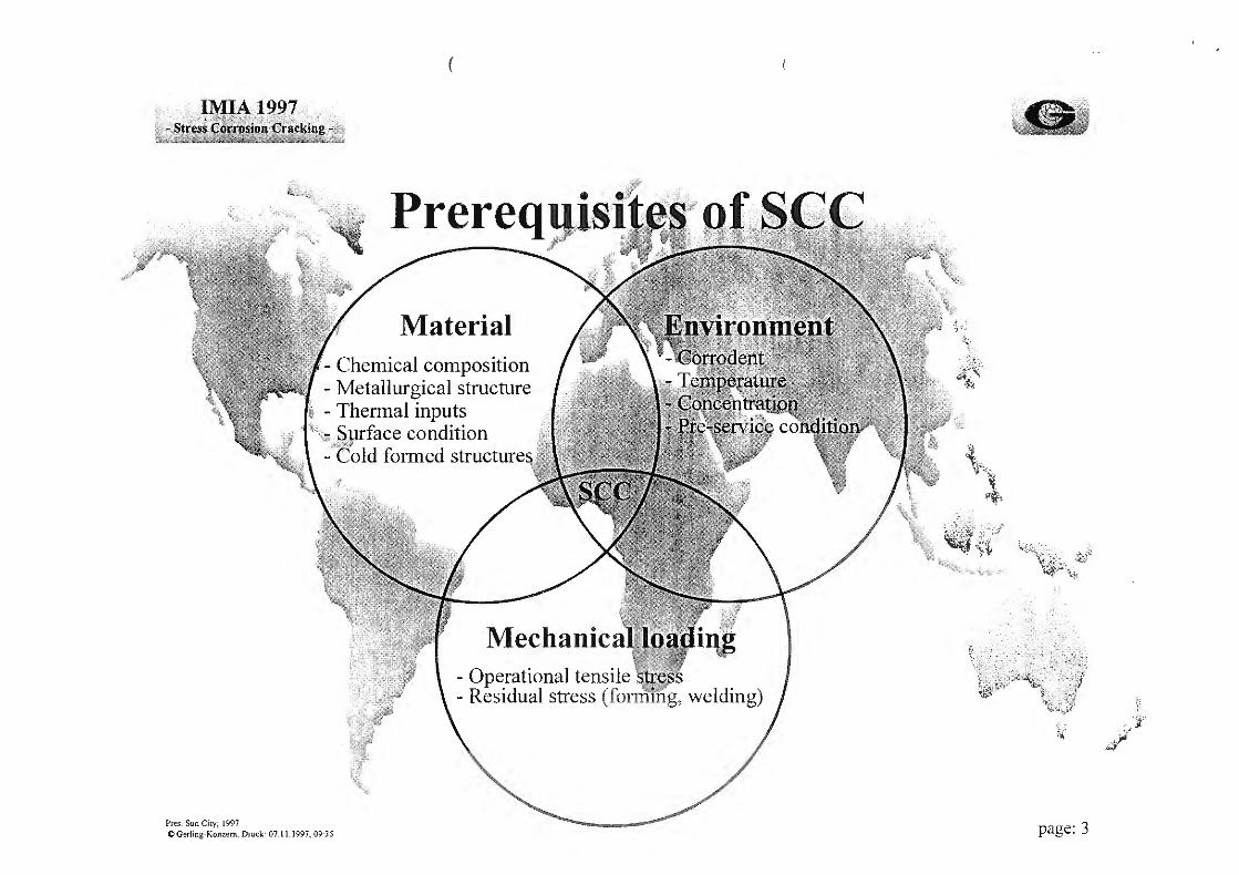
Stress corrosion cracking occurs in metal~ only under the simultaneous, combined effects of the following factors: a susceptible material, a specific environment, and a specific load. (See Attachment; Page 3):
The significant parameters of each of these conditions are in detail for the
Material: -Type -Average chemical composition -Metaliurgical structure (microstructure distribution of precipitates,
orientation of grains, dislocation interactions, amount of ferrite in cast stainless steel or austenitic-ferritic steel)
-Thermal inputs (heat treatment, welding-> sensitisation (migration of chromium carbides to the grain boundaries in austenitic stainless steel)) -Surface condition -Cold formed structure
Environment: -Composition I impurities -Temperature I threshold temperature -Concentration / leaching of other components -Pre-service conditions (e.g. contamination of surfaces)
Loading: -Operational tensile stress (concentration at notches, abrupt changes, wedges)
-Residual stress (cold forming, welding)
However there is no complete explanation why some environmental conditions cause cracking in one alloy and not in others. Brass, for example, fails if subjected to stress in the presence of ammonia, but copper I gold alloys do not.

4 IMIA 6 - 56 (97) E
Page 4 of the attachment offers a small overview of Alloy systems and environment.
If the surface of the material shows uniform corrosion or shallow pit formations, no stress. corrosion cracking will usually occur. Only deep pits i.e. pitting corrosion on the surface can produce cracking, if stresses are high enough.
As with most chemical reactions, stress corrosion cracking is accelerated by increasing temperature. Threshold temperatures have been identified from room temperature to high temperature.
In many cases it is difficult to measure the exact chemical composition of the surrounding electrolyte. Of course it is possible to measure the overall composition of moist gaseous or liquid flows. The composition under deposits, in sections with no flow or in condensed drops is not so easily determined. A further disturbance factor for the analysis is that normally the concentration in drops taken as samples is increased through evaporation of the water.
There are many different ways to bring corrosive agents into the fluid of a water-/ steamcycle. One must consider very carefully pre-service contamination (e.g. residues on the surface caused by fabrication, testing ,shipment or storage on site) and possible leaching of substances from other components in the circuit (e.g. chlorides and sulphides from concrete, gasket or insulation material).
The effect of mechanical load falls in two categories: those built in during manufacturing, producing residual stresses, and the applied loading from the normal operation of the component.
During manufacturing residual stresses can be caused by cold forming procedures, assembling processes as well as welding. The aforementioned welding is the most dangerous one. As a consequence of the heating and cooling effect on the surface of a component following welding, extremely high residual tensile stresses can occur, which can approach the yield point of the material.
The necessary amount of stress to initiate stress corrosion cracking is depending to a great extent on the other two factors environment and material. No general rules can be defined.
Investigations show, that the stress locally (at the crack front) often is above the yield point whereas the main section shows normal stress loading.
If the stress load is increased, the time until cracking occurs decreases.
Stress corrosion cracking often occurs at locations where stress concentrations are present during service as a consequence of the design of the component. Any kind of notch, keyway, perforations, screw threads, abrupt changes in shaft diameters,and the like should be assessed critically because of their susceptibility to SCC.
Stress corrosion cracking has only been observed in connection with tensile stresses. Compression stresses do not produce any stress corrosion cracking.

5 IMIA 6 - 56 (97) E
2.3 Characteristics:
2.3.1 Macroscopic:
The crack propagates perpendicular to Ille axis of principal stress in the component with no signs of plastic deformation. Even in hi~hly ductile materials no or little plastic deformation
~ occurs. The developing sharp notch a . the crack tip forms zones with very high stress concentrations.
Originating at surfaces, which usually only show slight corrosive attacks, the cracks can occur as a single crack or in greater n·1 .1bers. The surfaces of opened up cracks are usually velvety smooth, but can appear roug vben there is a greater incidence of intergranular constituents or more pronounced crad :anching.
2.3.2 Microscopic:
Stress corrosion cracking can occ1" in various modes: totally transgranular, totally intergranular, or mixed. Intergranular l ·acking means the cracks follow the boundaries of the grains. Transgranular cracking mean~ ~he cracks run straight through the grains with no preference to the grain boundaries. (~ ~e Attachment; Page 5):
Stress corrosion cracking is normally ir ·ergranular in Aluminium Alloys, Low Carbon Steels, Annealed Monel, a-Brass, and s;-·nsitised stainless steel, (at least initially). Intergranular or transgranular are Magnesium Alloys, Copper Alloys and Nickel Alloys. Intergranular and transgranular are austenitic steel in hot caustic media. Transgranular in P-Brass and in austenitic steel in combination with chlorides.
Exceptions to each of these general rules of crack appearance are known.
Transgranular stress corrosion cracking occurs more frequently in face-centred cubic metals (fee) such as austenitic steels. Body-centred cubic metals (bee), e.g. ferritic steel, are less susceptible. As a consequence the industry has developed a type of steel with a mixed microstructure, the so-called DUPLEX-steels. They have a considerably higher resistance against transgranular stress corrosion cracking.
Cracks vary in degree of branching or subsidiary cracks. Most cracks display multi branched ,,river-delta" patterns. They can though also occur without any branches.
2.4 Theory of mechanism:
The detailed mechanism to explain every aspect of the phenomenon of stress corrosion cracking has not been established yet. Several research programs are currently under way. All discussed theories have been observed in laboratory tests with the result that presently all of them have some degree of scientific support.
The currently discussed theories can be classified into one of the following groups /6/:

6 IMIA 6 - 56 (97) E
• Electrochemical active path dissolution theory:
An electrochemical cell is formed on the surface between two areas of slightly differing potential. The more active area becomes the anode (susceptible to corrosion) and in presence of an electrolyte the dissolution of metal commences. Because of the formation of a protective layer or passive skin at the sidewalls the corrosion is directed to the tip of the crack. In this small area stress causes the rupture of the protective film and new active material is exposed to further corrosion. Thus a sharp crack tip propagates through the material whereas the sides are protected and do not show any signs of uniform corrosion attack. In case of intergranular cracking the substance of the boundary is the active part and the crack follows the boundary line. (See Attachment; Page 6):
• Stress absorption theory
Stress weakens bonds between atoms on the metal surface, forming dislocations. At these dislocations ·damagiug ions are absorbed causing bonds to break and forming a crack in which adsorption continues.
• Corrosion tunnel theory:
Formations of rows of corrosion pits lengthen into an array of parallel corrosion tunnels. The uncorroded walls between the tunnels rupture mechanically to produce crack advancement.
• Hydrogen embrittlement or hydrogen induced stress corrosion cracking theory:
This theory is usually considered as a phenomenon of its own. (see chapter 2.1 above). Atomic hydrogen deposits at a cathode for any of several reasons. However, some atomic hydrogen can diffuse into the metallic lattice to embrittle the metal and increase internal stresses to ultimately form cracks. This kind of cracking occurs exclusively in unalloyed and low-alloy steels as well as martensitic steels. The susceptibility to this type is greatest around room temperature.
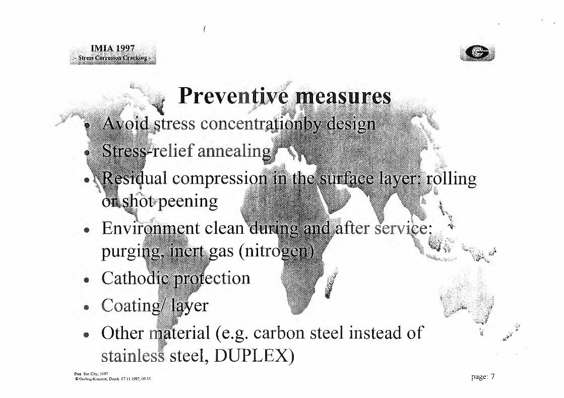
2.5 Preventive measures:
The preventive measure to reduce the risk of stress corrosion cracking to occur is based on the three prerequisites material, environment and stresses and include among others: (See Attachment; Page 7):
- Stress relief annealing where possible,
- Residual compression of the surface layer through rolling or shot peening, if annealing is not possible,
- Clean environment during and after service through purging, inert gas (nitrogen)
- A void stress concentration (any form of notches: abrupt changes, keyways, screw threads)
7 IMIA 6 - 56 (97) E
- Cathodic protection, with regard to hydrogen embrittlement
- Coating layer
- Other material : nickel-alloys instead 304 stainless steel stainless steel with Nb I Ti stabilising and low carbon content carbon steel instead of stainless steel ferritic-austenitic steel DUPLEX
In addition every susceptible component should be monitored throughout its whole life and capable for further examinations in case of evidence.
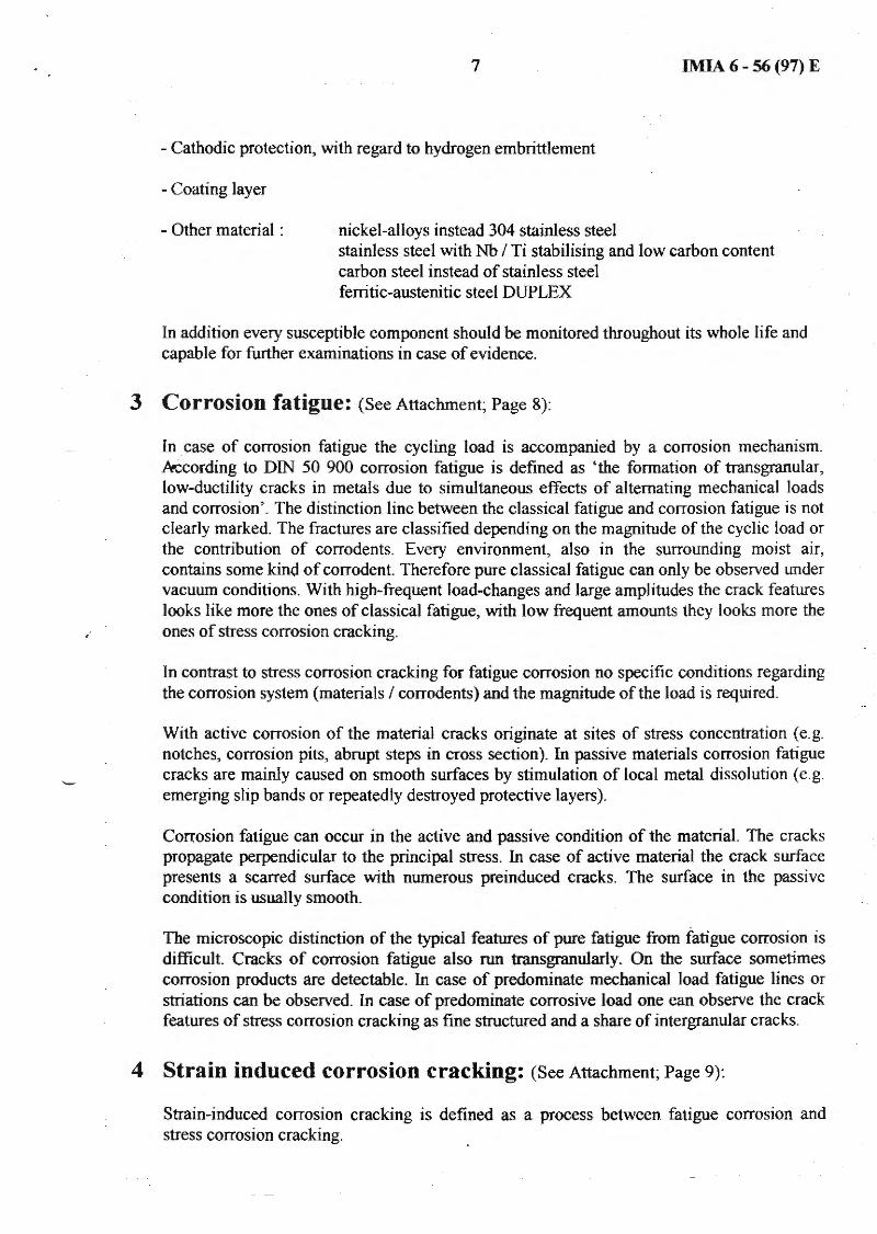
3 Corrosion fatigue: (See Attachment; Page 8):
In . case of corrosion fatigue the cycling load is accompanied by a corrosion mechanism. kcording to DIN 50 900 corrosion fatigue is defined as 'the formation of transgranular, low-ductility cracks in metals due to simultaneous effects of alternating mechanical loads and corrosion'. The distinction line between the classical fatigue and corrosion fatigue is not clearly marked. The fractures are classified depending on the magnitude of the cyclic load or the contribution of corrodents. Every environment, also in the surrounding moist air, contains some kind of corrodent. Therefore pure classical fatigue can only be observed under vacuum conditions. With high-frequent load-changes and large amplitudes the crack features looks like more the ones of classical fatigue, with low frequent amounts they looks more the ones of stress corrosion cracking.
In contrast to stress corrosion cracking for fatigue corrosion no specific conditions regarding the corrosion system (materials I corrodents) and the magnitude of the load is required.
With active corrosion of the material cracks originate at sites of stress concentration (e.g. notches, corrosion pits, abrupt steps in cross section). In passive materials corrosion fatigue cracks are mainly caused on smooth surfaces by stimulation of local metal dissolution (e.g. emerging slip bands or repeatedly destroyed protective layers).
Corrosion fatigue can occur in the active and passive condition of the material. The cracks propagate perpendicular to the principal stress. In case of active material the crack surface presents a scarred surface with numerous preinduced cracks. The surface in the passive condition is usually smooth.
The microscopic distinction of the typical features of pure fatigue from fatigue corrosion is difficult. Cracks of corrosion fatigue also run transgranularly. On the surface sometimes corrosion products are detectable. In case of predominate mechanical load fatigue lines or striations can be observed. In case of predominate corrosive load one can observe the crack features of stress corrosion cracking as fine structured and a share of intergranular cracks.
4 Strain induced corrosion cracking: (See Attachment; Page 9):
Strain-induced corrosion cracking is defined as a process between fatigue corrosion and stress corrosion cracking.

8 IMIA 6 - 56 (97) E
In DIN 50900 it is described as ,,Local corrosion with crack forming in metals as a consequence of a mechanical damage of protective coatings due to repeated critical stretching or shrinking of a component".
This means a protective layer build by the material, e.g. magnetite layer in pipes of steam boilers, is destroyed as a result of strain reversal due to mechanical stresses, and the free surface is exposed to a corrosive attack. The strain reversal can be a consequence of quickly changing operation condition, e.g. fluctuating steam pressure. It can also happen that the expansion of a component is hindered by the construction and the resulting compression stresses in the protective layers crack the coating. With every load cycle the mechanism is repeated at the crack tip, supported by the stress concentration due to the notch, and the crack propagates through the material.
Strain-induced corrosion cracking is limited to materials which build distinct protective coatings.
The macroscopic characteristics are usually a small number of individual cracks on the surface, perpendicular to the tensile stress. The surfaces of opened up cracks are generally smooth.
Regarded through a microscope, the cracks run transgranularly. Sometimes corrosion products can be detected.
5 Conclusions: (See Attachment; Pages 10 and 11):
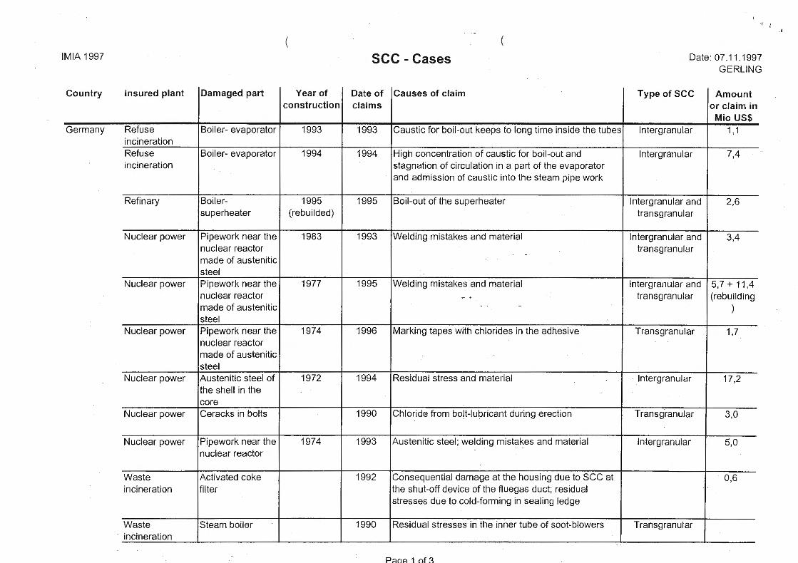
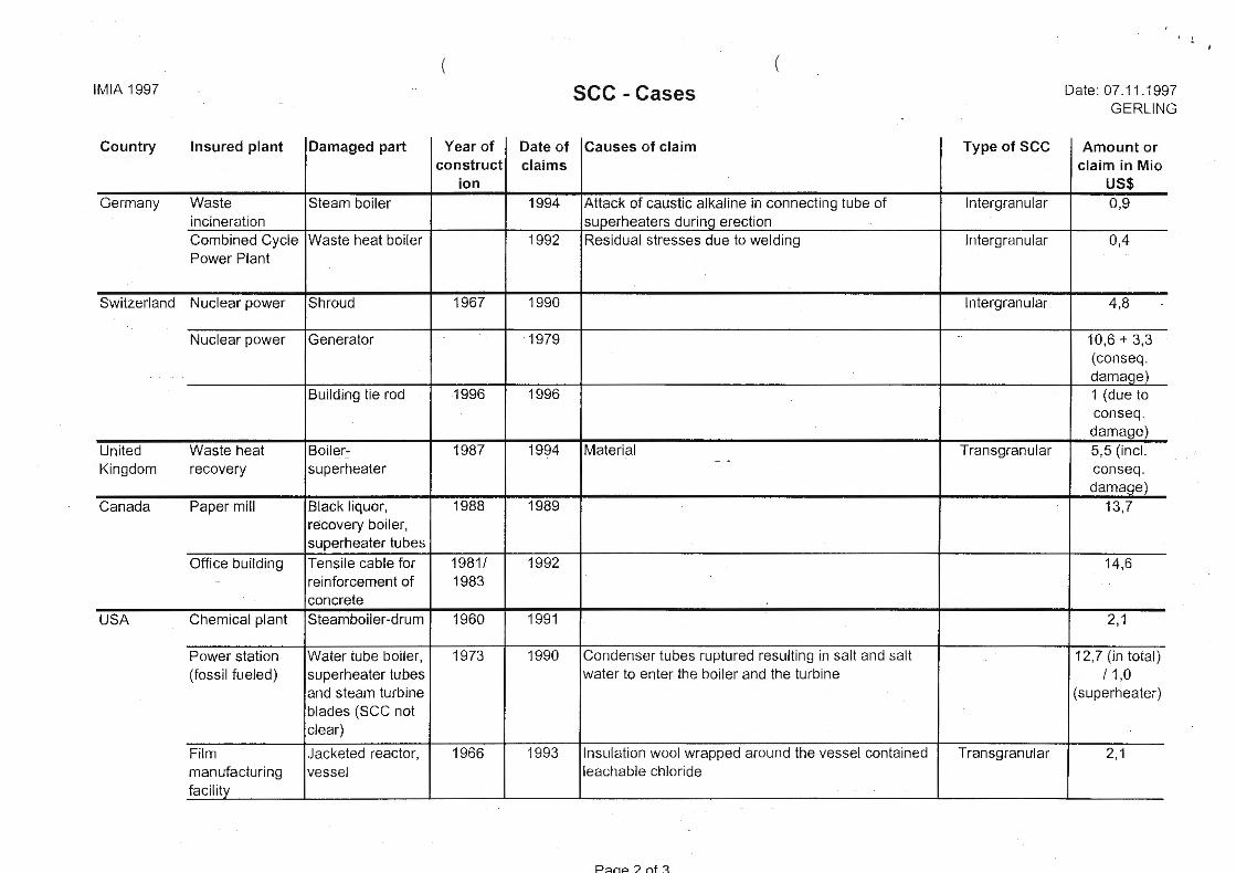
6 Cases: (See Attachment: sec -Cases; Pages 1 - 3):
7 Literature:
Ill Rasterelektronenmikroskopische Untersuchungen von Metallschaden L. Engel/ H. Klingele Gerling Institut fur Schadenforschung und Schadenverhtitung, Koln, 1974
121 The Appearance of cracks and fractures in metallic materials Stahl und Eisen
131 Systematic Analysis of technical failures G. Lange Deutsche Gesellschaft fur Metallkunde 1986
141 Korrosion der Metalle, Begriffe DIN 50 900, Teil 1 Deutsches Institut fur Normung e.V., April 1982

9
1151 Problems of stress corrosion cracking in engineering insurance R B. Schittek IMIA 6-39(87)E
161 Stress corrosion cracking D. Anliker THE LOCOMOTIVE
171 SpannungsriBkorrosion - SpRK P. Forchhammer Lecture Paper 1996
IMIA 6 - 56 (97) E

(
Stress corro
• -Classi · -Cha -App -Theo
• Corros ·· ... ~ .. . >
• Strain in ·.··
• Conclusi(}n . \a'
Pres. Sun City; 1997 OGcrling·Konzcm. Druck: 07.11.1997; 09.35 page: 1

(
' . 1cat1on
Relaxation crack
Shrinkage crack
Welding crack
Service induced
Creep crack
Thermal shock crack Hydrogen induced SCC
based on 121 Hydrogen induced
Prcs. Sun City; 1997 0 Gerli ng-Konzcm, Druck: 07.11.1997; 09:35 page:2
(
Material - Chemical composition - Metallurgical structure
~ - Thermal inputs , '~.4~face condition
- Cold formed structure
Mechanica - Operational tensile - Residual stress (form
Pres. Sun City; 1997 0 Gerling-Konzem, Druck 07.1LI997, 09J S page: 3

Precipitatio Steel Inconel Nickel Alloys Aluminilllll
Copper Alloys Gold Alloys Magnesilllll Alloys Monel Titanic Alloys
Pres. Sun City; 1997 0 Gerling· Konzem, Druck: 07.11.1997; 09.35
SodilllllHy Acidic H Marine
" Polythionic Acids,
Caustic Sodilllll Hydr Chloride soluti Sulfide .·~ .
~
!~--·/
Ammonia Vap olW,ions, Amines, Mercury C01ppp~ Chlorides, Hyp e S~lutions, Acetic Acid-Salt So · · ·' Chloride Solutio ural and Coastal Atmospheres Fused Caustic Soda, Hydrofluorid Acid, Mercury Nitric Acid, Hot Chloride Solutions, Methanol, Ethanol
page:4

transgra
Intergran transgranul
Transgran
Pres. Sun City; 1997 0 Gerl ing-Konzern, Druck: 07.11 .1997; 09:35
(
I Aluminium allo
Low carbons
a-Brass
Sensitize initially)
Magnesium alloy kel alloys
Austenite (chlorides)
Trans granular
page: 5

e- ~H or} 2H 0 + li.e-~ 40H-2
Pres. Sun Ci ty~ 1997 O Gerling-Konzern, Druck: 07.11.1997; 09:35 page: 6
(
elief annealin
ual compressi ~ . . ,. ~ . ot,peen1ng
• Envir-'2-~ ·i ~ nt clean
purgi as (nitr
• Catho
• • Other . terial (e.g. carbon steel instead of
stainles . steel, DUPLEX) Pres . Sun City; 1997 0 Gerling-Konzern, Druck: 07.11.1997; 09:35 page: 7

Pres Sun City; 1997 0 Gerling-Ko nzern, Druck: 07.11.1997; 09:35
(
,Corr~sjo
.ii
page: 8

(
Pres . Sun City; 1997 0 Gerl ing-Konzem, Druck: 07. 11.1 997; 09.35 page: 9
( IMIA 1997
Country Insured plant Damaged part Year of construction
Germany Refuse Boiler- evaporator 1993 incineration Refuse Boiler- evaporator 1994 incineration
Refinary Boiler- 1995 superheater (rebuilded)
Nuclear power Pipework near the 1983 nuclear reactor made of austenitic steel
Nuclear power Pipework near the 1977 nuclear reactor made of austenitic steel
Nuclear power Pipework near the 1974 nuclear reactor made of austen itic steel
Nuclear power Austenitic steel of 1972 the shell in the core
Nuclear power Ceracks in bolts
Nuclear power Pipework near the 1974 nuclear reactor
Waste Activated coke incineration filter
Waste Steam boiler incineration
(
SCC-Cases
Date of Causes of claim claims
1993 Caustic for boil-out keeps to long time inside the tubes
1994 High concentration of caustic for boil-out and stagnation of circulation in a part of the evaporator and admission of caustic into the steam pipe work
1995 Boil-out of the superheater
1993 Welding mistakes and material
1995 Welding mistakes and material ~ .
1996 Marking tapes with chlorides in the adhesive
1994 Residual stress and material
1990 Chloride from bolt-lubricant during erection
1993 Austenitic steel; welding mistakes and material
1992 Consequential damage at the housing due to SCC at the shut-off device of the fluegas duct; residual stresses due to cold-forming in sealing ledge
1990 Residual stresses in the inner tube of soot-blowers
P ;::inP. 1 of~
Date: 07.11.1997 GERLING
Type of sec Amount or claim in
Mio US$ lntergranular 1, 1
lntergranular 7,4
lntergranular and 2,6 transgranular
lntergranular and 3,4 transgranular
lntergranular and 5,7+11,4 transgranular (rebuilding
)
Transgranular 1,7
lntergranular 17,2
Transgranular 3,0
lntergranular 5,0
0,6
Transgranular
(
IMIA 1997
Country Insured plant Damaged part Year of construct
ion Germany Waste Steam boiler
incineration Combined Cycle Waste heat boiler Power Plant
Switzerland Nuclear power Shroud 1967
Nuclear power Generator
Building tie rod 1996
United Waste heat Boiler- 1987 Kingdom recovery superheater
Canada Paper mill Black liquor, 1988 recovery boiler, superheater tubes
Office build ing Tensile cable for 1981/ reinforcement of 1983 concrete
USA Chemical plant Steamboiler-drum 1960
Power station Water tube boiler, 1973 (fossil fueled) superheater tubes
and steam turbine blades (SCC not clear)
Film Jacketed reactor, 1966 manufacturing vessel faci lity
(
SCC - Cases
Date of Causes of claim Type of sec claims
1994 Attack of caustic alkaline in connecting tube of lntergranular superheaters during erection
1992 Residual stresses due to welding lntergranular
1990 lntergranular
1979
1996
1994 Material Transgranular ~ .
1989
1992
1991
1990 Condenser tubes ruptured resulting in salt and salt water to enter the boiler and the turbine
1993 Insulation wool wrapped around the vessel contained Transgranular leachable chloride
P:::inP ? nf ~
Date: 07 .11 .1997 GERLING
Amount or claim in Mio
US$ 0,9
0,4
4,8
10,6 + 3,3 (conseq. damaqe) 1 (due to conseq. damage) 5,5 (incl. conseq. damage)
13,7
14,6
2, 1
12,7 (in total) I 1,0
( superheater)
2, 1

( IMIA 1997
Country Insured plant Damaged part Year of Date of construct claims
ion USA Refinery Absober column 1984
with propane in amine service
Power station Steam turbine, 1980 disk failure (last stage) Ammonia storage 1973 tank
Japan Power station Gas turbine 1994 1994
Chemical plant Steam turbine 1991 1989
Chemical plant Steam turbine 1991 1989
SCC -Cases
Causes of claim
Repair weld 10 years ago: 4 pre-rupture cracks in HEZ
Poor material
Ammonia service
Fuel gas with corrosive ingredients
Na-salt in the steam
Na-salt in the steam
Page 3 of 3
Type of sec
..
Date: 07.11.1997 GERLING
Amount or claim in Mio
US$ Hydrogen induced 152,4
cracking physical damage+
75,0
1,5
2,4
1,0
1,0


