ELEKTRONIKA IR ELEKTROTECHNIKA, ISSN 1392-1215, VOL. 23, NO. 3, 2017 1 Abstract—Industry 4.0 promotes the integration of IT software technology with the industrial devices of a factory for the supervision and control of Industrial Automation Systems (IAS). In this paper, a novel metamodel called iMMAS (Industrial Meta-Model for Automation System) is proposed to simplify the development and deployment of an IAS. The metamodel provides a language for modelling the industrial process of a factory through industrial devices (including PLC, Soft-PLC or RTU) using new abstractions to conceptualize the IAS. This work presents how the models are performed and executed on an OPC UA environment, and how they can be used to generate a program for a PLC. A case study is also shown to test the applicability of the proposal presented. Index Terms—OPC unified architecture; industrial metamodel; software engineering; human machine interface (HMI); mobile device; supervision control and data acquisition (SCADA); methodology. I. INTRODUCTION Software development is an extensive area generally related with information technology and computing science, focused on the methodologies, software infrastructures, techniques and tools that can assist the development of complex and large software projects. In industrial environments, the traditional techniques employed for the management of software development and deployment are not being systematically used for several reasons. Firstly, industrial systems, in practice, may not include software or its use might be limited, due to the investment in terms of money and time, especially in very simple productive processes where it does not need precise control by software; e.g., although a simple pneumatic system can have just one button to start and another one to stop, it can include also a software module for monitoring the operation of the compressor in a smart display. Secondly, many software tools have to be managed individually with a limited integration among them. And lastly, the traditional programming tools for industry do not have support for software engineering techniques [1]. In an Industrial Automation System (IAS), the main part of the developed software is largely based on Programmable Logic Controllers (PLC) [2]. The software for these devices is based on the development of sequential programs and, in some cases, structured programming using structures such as Manuscript received 2 November, 2016; accepted 23 March, 2017. function blocks. In this scenario, some standards were developed to standardize PLCs in industrial systems as well as the programming languages that could be used, such as IEC 61131-3 [3]. But this standard is only focused on PLC programming and it does not contemplate how industrial systems should be organized regarding other levels. Many well-established paradigms of IT such as the Object-Oriented Programming (OOP) and the Development of Model Driven Software (MDD) are not sufficiently exploited in industrial systems. For instance, the IEC 61499 standard provides support for OOP [4], although, despite being 10 years in the market now, it has not been fully adopted by the industry [5]. The application of MDD and SOA paradigms is more limited and, therefore, it is not yet clear how they must be adopted [6]. On the other hand, software requirements in current industrial systems are becoming a major need. In fact, in the last decade, the ratio of software development with respect to the costs of machinery has doubled from 20 % to 40 % and this trend continues to increase progressively [6]. Moreover, the industrial companies have to adapt quickly to the market developing flexible, scalable systems easy to maintain for reducing the costs of the production process and time-to-market, improving the product quality, reducing energy consumption and contributing to environment sustainability. These challenges are very difficult to confront with traditional approaches. The use of software engineering techniques is necessary in order to provide systematic methods to design and develop industrial processes, and, furthermore, to determine how they are deployed on the different computing devices involved, such as the PLC, the Machine Interface (HMI) systems (or Supervisory Control And Data Acquisition (SCADA)), and the intermediate systems between PLC and HMI/SCADA. Model Driven Engineering (MDE) is a software engineering paradigm that promotes the creation of conceptual models procuring an abstract representation of the requirements, functionalities and any other topic related to a specific problem to be solved by a software system. Then, from these models and the application of a systematic methodology, the engineer can generate an implementation of the system that is correct-by-construction. The supervision of an industrial process requires the iMMAS an Industrial Meta-Model for Automation System Using OPC UA Jose Miguel Gutierrez-Guerrero 1 , Juan Antonio Holgado-Terriza 1 1 Software Engineering Department, University of Granada, C/ Periodista Daniel Saucedo Aranda s/n. 18071 Granada, Spain [email protected]http://dx.doi.org/10.5755/j01.eie.23.3.18324 3
Transcript
ELEKTRONIKA IR ELEKTROTECHNIKA, ISSN 1392-1215, VOL. 23, NO. 3, 2017
1Abstract—Industry 4.0 promotes the integration of ITsoftware technology with the industrial devices of a factory forthe supervision and control of Industrial Automation Systems(IAS). In this paper, a novel metamodel called iMMAS(Industrial Meta-Model for Automation System) is proposed tosimplify the development and deployment of an IAS. Themetamodel provides a language for modelling the industrialprocess of a factory through industrial devices (including PLC,Soft-PLC or RTU) using new abstractions to conceptualize theIAS. This work presents how the models are performed andexecuted on an OPC UA environment, and how they can beused to generate a program for a PLC. A case study is alsoshown to test the applicability of the proposal presented.
Index Terms—OPC unified architecture; industrialmetamodel; software engineering; human machine interface(HMI); mobile device; supervision control and data acquisition(SCADA); methodology.
I. INTRODUCTION
Software development is an extensive area generallyrelated with information technology and computing science,focused on the methodologies, software infrastructures,techniques and tools that can assist the development ofcomplex and large software projects. In industrialenvironments, the traditional techniques employed for themanagement of software development and deployment arenot being systematically used for several reasons. Firstly,industrial systems, in practice, may not include software orits use might be limited, due to the investment in terms ofmoney and time, especially in very simple productiveprocesses where it does not need precise control bysoftware; e.g., although a simple pneumatic system can havejust one button to start and another one to stop, it can includealso a software module for monitoring the operation of thecompressor in a smart display. Secondly, many softwaretools have to be managed individually with a limitedintegration among them. And lastly, the traditionalprogramming tools for industry do not have support forsoftware engineering techniques [1].
In an Industrial Automation System (IAS), the main partof the developed software is largely based on ProgrammableLogic Controllers (PLC) [2]. The software for these devicesis based on the development of sequential programs and, insome cases, structured programming using structures such as
Manuscript received 2 November, 2016; accepted 23 March, 2017.
function blocks. In this scenario, some standards weredeveloped to standardize PLCs in industrial systems as wellas the programming languages that could be used, such asIEC 61131-3 [3].
But this standard is only focused on PLC programmingand it does not contemplate how industrial systems shouldbe organized regarding other levels. Many well-establishedparadigms of IT such as the Object-Oriented Programming(OOP) and the Development of Model Driven Software(MDD) are not sufficiently exploited in industrial systems.For instance, the IEC 61499 standard provides support forOOP [4], although, despite being 10 years in the marketnow, it has not been fully adopted by the industry [5]. Theapplication of MDD and SOA paradigms is more limitedand, therefore, it is not yet clear how they must be adopted[6].
On the other hand, software requirements in currentindustrial systems are becoming a major need. In fact, in thelast decade, the ratio of software development with respectto the costs of machinery has doubled from 20 % to 40 %and this trend continues to increase progressively [6].Moreover, the industrial companies have to adapt quickly tothe market developing flexible, scalable systems easy tomaintain for reducing the costs of the production processand time-to-market, improving the product quality, reducingenergy consumption and contributing to environmentsustainability.
These challenges are very difficult to confront withtraditional approaches. The use of software engineeringtechniques is necessary in order to provide systematicmethods to design and develop industrial processes, and,furthermore, to determine how they are deployed on thedifferent computing devices involved, such as the PLC, theMachine Interface (HMI) systems (or Supervisory ControlAnd Data Acquisition (SCADA)), and the intermediatesystems between PLC and HMI/SCADA.
Model Driven Engineering (MDE) is a softwareengineering paradigm that promotes the creation ofconceptual models procuring an abstract representation ofthe requirements, functionalities and any other topic relatedto a specific problem to be solved by a software system.Then, from these models and the application of a systematicmethodology, the engineer can generate an implementationof the system that is correct-by-construction.
The supervision of an industrial process requires the
iMMAS an Industrial Meta-Model forAutomation System Using OPC UA
Jose Miguel Gutierrez-Guerrero1, Juan Antonio Holgado-Terriza1
1Software Engineering Department, University of Granada,C/ Periodista Daniel Saucedo Aranda s/n. 18071 Granada, Spain
ELEKTRONIKA IR ELEKTROTECHNIKA, ISSN 1392-1215, VOL. 23, NO. 3, 2017
monitoring of thousands of signals, each one in charge ofsome specific aspects. Thus, a modelling of industrialprocesses from the requirements can help engineers toorganize the software from both structural and behaviouralviews. MDE can give an additional abstraction layer,generalizing the common patterns and elements that governa specific industrial process into a meta-model. As a result,the meta-model provides a common language to express theindustrial elements participating in the industrial process,including the behaviour of these elements.
Accordingly, MDE contributes to the definition of newconcepts to the Industry 4.0 [7], [8], where a smart factorycan help to achieve integrated and easily reconfigurableindustrial systems covering the production demands,according to the needs of the increasingly changing market.In this sense, all the elements of our IAS are based on amodel that can be improved by the introduction of behaviourmodelling and transformation rules [9].
In this paper, a novel meta-model called iMMAS(Industrial Meta-Model for Automation System) is proposedto simplify the development and deployment of an IAS. Themeta-model provides a language with a concrete syntax andspecific semantic for modelling those industrial devices(including PLC, Soft-PLC or RTU) using new abstractionsto conceptualize the IAS. Thereby, the meta-model gives aset of rules and a method to assist the engineer/developer inthe modelling process.
Besides, models carried out with iMAAS can be run in anexecutable environment at runtime inside the scope of OPCUA technology. That is, an OPC UA client from a third-party can access to the OPC UA server and can managedirectly the iMMAS models, disengaging the industrialprocesses and hiding the industrial devices of the factoryplant.
Finally, iMMAS can address the software developmentprocess of industrial devices from iMMAS models accordingto a model-driven approach. In this way, the development ofan IAS is performed by using high-level abstractions insteadof using low-level abstractions at PLC level.
In section II, a contextualization of different standard andsoftware engineering techniques used within the industrialsystem is summarized and the current situation of relevantstandards related with industrial systems is revised. SectionIII presents iMMAS focusing on the two first levels of themeta-model, and the general rules to deploy a model onOPC-UA server and to generate a PLC program. Section IVexplains how to create a specific model based on iMMAS,and how to deploy it in a software control system to managea modelled climate room as an example. Finally, the lastsection covers the conclusions and future works.
II.BACKGROUND
The industrial community has developed several standardsduring the last years to regulate the process of softwaredevelopment for specific industrial devices, integrating thesoftware of different machines placed in a factory plant.
For example, IEC 61131-3 standard is oriented to theprogramming of PLC devices [4], and its last version (thirdedition) includes a specific extension to support object-oriented programming [10]. However, ISA-88 standard [6]
is focused on issues related with system configuration andsystem integration, specifically for process control systemson batch, although it can also be applied to discrete,continuous, hybrid, and storage process control [11]. In thissense, the ISA-95 standard (standardized internationally asIEC 62264 [12]) delves into how the integration betweenIAS systems and business systems like ERP (EnterpriseResource Planning) and MES (Manufacturing ExecutingSystem) can be done, defining the interface between controlfunctions/systems and other enterprise functions/systems.
A software developer on IAS will face a laborious workrelated with integration and deployment issues betweensystems [13], horizontal (e.g., communication HMI to HMI)and vertical (e.g. communication BATCH systems and MESsystem). In addition, the software developer has to developthe IAS system; that is, programming PLC devices and HMIsystems (usually SCADA systems), and establishing thecommunication between both systems [14].
Unfortunately, the aforementioned standards provide onlygeneral rules for guiding and they do not include anysoftware development methodology [9]. Conversely, MDEhas been successfully applied to the development of ITsystems [15]. It provides a methodology driven by models,structuring the development of a complex system in separateabstraction levels, from conceptual high-level models toimplementation low-level models. Then, the softwaredevelopment process implies a transformation betweenmodels until a low level model, the program, is constructed.The separation of the software development at two levels,the design of high-level conceptual models to conceptualizeabstractions, and the development based on thetransformation between models on different domains, givethe essential pillars of MDE [16].
The MDE application to IAS can be similar to IT systems[10]. The industrial systems can be seen as models atdifferent levels: at PLC programming domain, where thesignals are captured to reflect the physical environment; atOPC domain, where the signals are captured as data to beexposed to the rest of industrial systems; and, finally, at aMES domain, where the industrial process is governed.Then, it is potentially possible to perform models at differentdomain levels, and the definition of rules to performtransformations between domains.
The Object Management Group (OMG) [17] is a non-profit organization especially oriented towards businessinformation technology, who defines and guides theapplication of MDE paradigm to IT systems. In fact, theydefined a number of standards for MDE, in particular model-driven architecture (MDA), based on MetaObject Facility(MOF) [18] and Unified Modelling Language (UML) [19].UML provides a number of diagram representations tocapture the requirements, structure, behaviour and even therefinements to executable code, although it does not definethe methodology to be applied to develop the software.System Modeling Language (SysML) [20] is a UMLderivative for system engineering applications that is gettingincreasingly popular; e.g. in Manufacturing Machinery [21].In particular, SysML supports specific diagramrepresentations such design phases for capturing andformalizing the requirements.
4
ELEKTRONIKA IR ELEKTROTECHNIKA, ISSN 1392-1215, VOL. 23, NO. 3, 2017
There are several works related with the using of UML insoftware engineering [6]. On one hand, Papakonstantinou etal. proposed a way to generate IEC 61499 function blocksfrom UML diagrams [22]. On the other hand, Thramboulidisdescribed a UML-FB architecture for generating UMLdiagrams to build Function Blocks [5]. Moreover, Fan et al.developed an extension to UML for industrial system calledUML-PA (UML for Process Automation) [23].
The use of software methodology to IAS domain could bevery beneficial and could reduce the time of design anddeveloping industrial system. Unfortunately, they are notcurrently specific tools adapted to IAS [6].
Although the application of MDE paradigm and softwareengineering were limited, the manufacturers of industrialdevices can develop some specific software tools to resolvespecific issues such as the PLC programming, the definitionof simple data models of PLCs, or the configuration andintegration of industrial devices in SCADA. In industrialsystems, OPC (Ole for process control) [24] systems providea common way to decouple the control domain from theinstrument domain, providing a communication interface tostandardize the data exchange with industrial devices using adata access model. Recently, the OPC Foundation [25] hasreleased OPC UA [26], a standard that has native support formodelling and deployment of models directly, opening thepossibility of applying MDE paradigm for IAS in order todevelop software driven by models. This paper shows aproposal of how OPC UA [27] can exploit MDE principlesto develop industrial systems.
III. INDUSTRIAL META MODEL FOR AUTOMATION SYSTEM(iMMAS)
iMMAS (Industrial meta model for automation systems) isa specific meta-model conceived for the development anddeployment of an industrial automation system based on amodel-driven approach. The meta-model of iMMASprovides a common language with a concrete syntax andspecific semantic, which is adapted from the informationmodel of OPC UA, in order to model any IAS.
The modelling process defined in iMMAS provides asystematic method for characterizing the industrial elementsthat are involved in an industrial process. The models can beexecuted directly on OPC UA environments using client-server architecture, facilitating in this way its integrationwith other industrial systems. The models are stored
persistently in an OPC UA server using the address model ofOPC UA and data are collected from industrial hardwaredevices (e.g., PLC). All models and data are kept on an OPCUA server, which is accessible for any integrated system thatacts as an OPC UA client. Furthermore, models created fromiMMAS metamodel can help to generate a program forindustrial devices transparently to the developer in order tosimplify the signal capturing and storing further on the OPC-UA server. For instance, the program loads on a PLC devicecan be obtained directly by transformation of iMMASmodels. Figure 1 shows the relevant features of an iMMASinfrastructure.
Fig. 1. The meta-model of iMMAS provides a language for designingmodels of IAS that can be executed on OPC-UA servers and can generate aprogram for PLC devices.
A. iMMAS Meta-ModelThe meta-model establishes the bases of the modelling
language defined by iMMAS to model any industrial processand the structure of the industrial devices at differentabstraction layers. Moreover, developed models areindependent of the software and hardware platform, sincethey are managed as abstractions that can be implemented inany programming language supporting abstract objects ordata definition and can be further deployed on specifichardware or software platform.
The models conforming to iMMAS are also based on theinformation model of OPC UA, which it allows executingdirectly the models on an OPC UA environment asexecutable models. Figure 2 shows the main abstractionsemployed by the information model of OPC UA, whileFig. 3 shows an example of how the new abstractions ofiMMAS are built over the model of OPC UA.
Fig. 2. Basic and Main concepts of OPC UA data Metamodel.
5
ELEKTRONIKA IR ELEKTROTECHNIKA, ISSN 1392-1215, VOL. 23, NO. 3, 2017
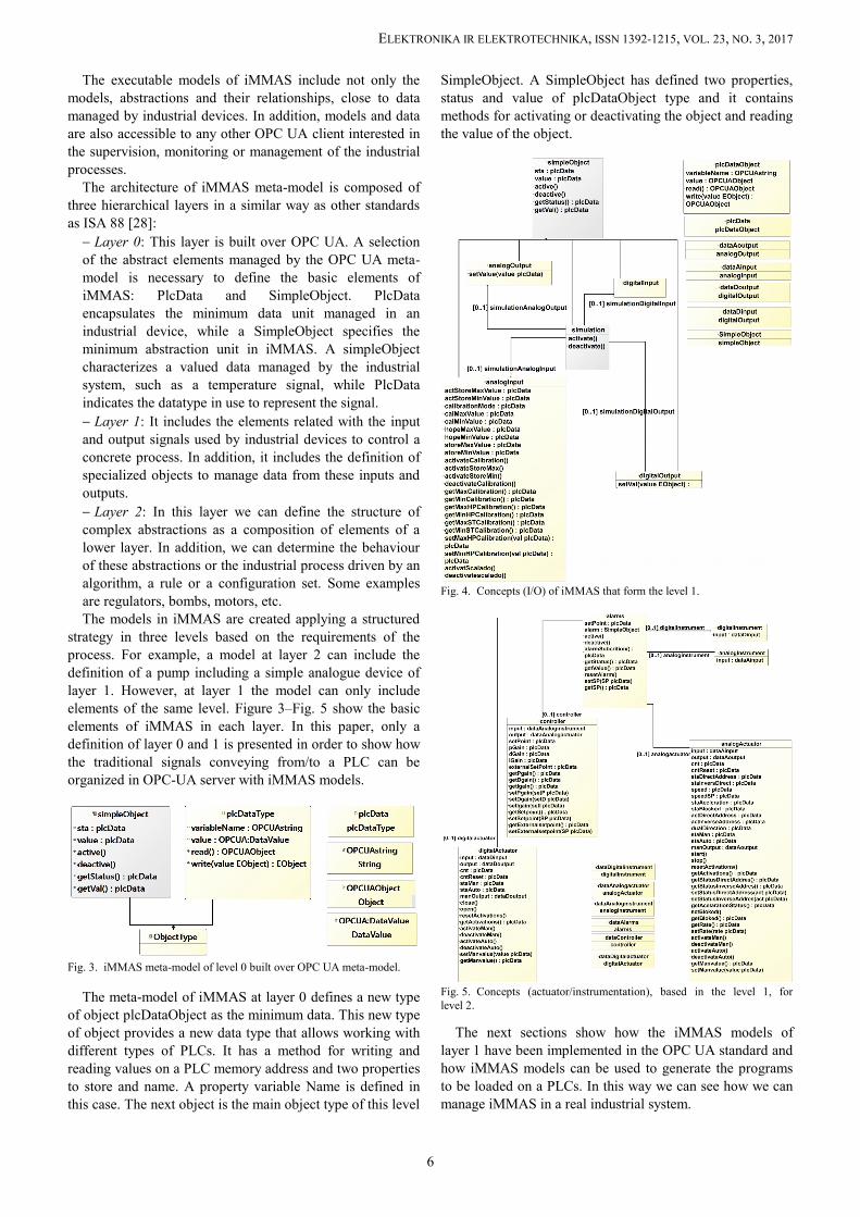
The executable models of iMMAS include not only themodels, abstractions and their relationships, close to datamanaged by industrial devices. In addition, models and dataare also accessible to any other OPC UA client interested inthe supervision, monitoring or management of the industrialprocesses.
The architecture of iMMAS meta-model is composed ofthree hierarchical layers in a similar way as other standardsas ISA 88 [28]: Layer 0: This layer is built over OPC UA. A selectionof the abstract elements managed by the OPC UA meta-model is necessary to define the basic elements ofiMMAS: PlcData and SimpleObject. PlcDataencapsulates the minimum data unit managed in anindustrial device, while a SimpleObject specifies theminimum abstraction unit in iMMAS. A simpleObjectcharacterizes a valued data managed by the industrialsystem, such as a temperature signal, while PlcDataindicates the datatype in use to represent the signal. Layer 1: It includes the elements related with the inputand output signals used by industrial devices to control aconcrete process. In addition, it includes the definition ofspecialized objects to manage data from these inputs andoutputs. Layer 2: In this layer we can define the structure ofcomplex abstractions as a composition of elements of alower layer. In addition, we can determine the behaviourof these abstractions or the industrial process driven by analgorithm, a rule or a configuration set. Some examplesare regulators, bombs, motors, etc.The models in iMMAS are created applying a structured
strategy in three levels based on the requirements of theprocess. For example, a model at layer 2 can include thedefinition of a pump including a simple analogue device oflayer 1. However, at layer 1 the model can only includeelements of the same level. Figure 3–Fig. 5 show the basicelements of iMMAS in each layer. In this paper, only adefinition of layer 0 and 1 is presented in order to show howthe traditional signals conveying from/to a PLC can beorganized in OPC-UA server with iMMAS models.
Fig. 3. iMMAS meta-model of level 0 built over OPC UA meta-model.
The meta-model of iMMAS at layer 0 defines a new typeof object plcDataObject as the minimum data. This new typeof object provides a new data type that allows working withdifferent types of PLCs. It has a method for writing andreading values on a PLC memory address and two propertiesto store and name. A property variable Name is defined inthis case. The next object is the main object type of this level
SimpleObject. A SimpleObject has defined two properties,status and value of plcDataObject type and it containsmethods for activating or deactivating the object and readingthe value of the object.
Fig. 4. Concepts (I/O) of iMMAS that form the level 1.
Fig. 5. Concepts (actuator/instrumentation), based in the level 1, forlevel 2.
The next sections show how the iMMAS models oflayer 1 have been implemented in the OPC UA standard andhow iMMAS models can be used to generate the programsto be loaded on a PLCs. In this way we can see how we canmanage iMMAS in a real industrial system.
6
ELEKTRONIKA IR ELEKTROTECHNIKA, ISSN 1392-1215, VOL. 23, NO. 3, 2017
B. Deployment on OPC UA ServerOPC UA provides a more flexible approach for
controlling and supervising an industrial process than classicOPC. The inclusion of iMMAS over OPC UA gives anadditional flexibility to manage data of control processes.Commercial OPC UA clients have usually a lack of supportfor accessing abstract models of OPC UA servers. For thisreason, we have developed a specific HMI application as anOPC UA client, which invokes the methods of iMMASobjects for controlling and monitoring the industrial process.
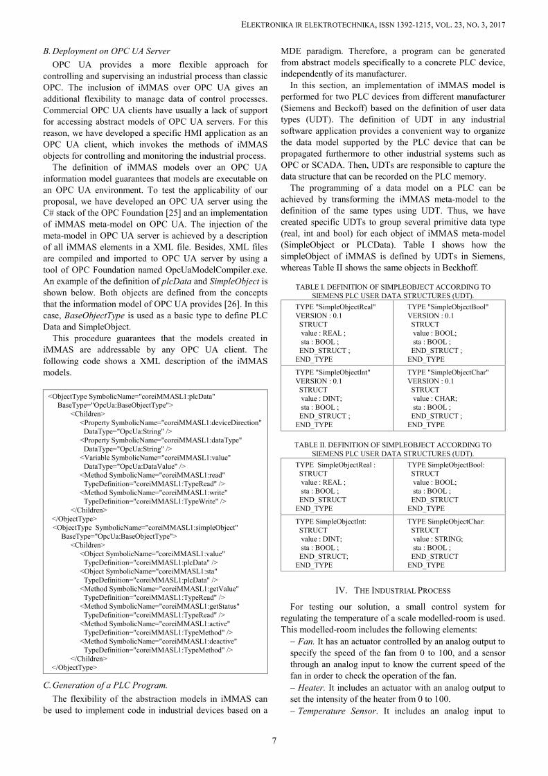
The definition of iMMAS models over an OPC UAinformation model guarantees that models are executable onan OPC UA environment. To test the applicability of ourproposal, we have developed an OPC UA server using theC# stack of the OPC Foundation [25] and an implementationof iMMAS meta-model on OPC UA. The injection of themeta-model in OPC UA server is achieved by a descriptionof all iMMAS elements in a XML file. Besides, XML filesare compiled and imported to OPC UA server by using atool of OPC Foundation named OpcUaModelCompiler.exe.An example of the definition of plcData and SimpleObject isshown below. Both objects are defined from the conceptsthat the information model of OPC UA provides [26]. In thiscase, BaseObjectType is used as a basic type to define PLCData and SimpleObject.
This procedure guarantees that the models created iniMMAS are addressable by any OPC UA client. Thefollowing code shows a XML description of the iMMASmodels.
C.Generation of a PLC Program.The flexibility of the abstraction models in iMMAS can
be used to implement code in industrial devices based on a
MDE paradigm. Therefore, a program can be generatedfrom abstract models specifically to a concrete PLC device,independently of its manufacturer.
In this section, an implementation of iMMAS model isperformed for two PLC devices from different manufacturer(Siemens and Beckoff) based on the definition of user datatypes (UDT). The definition of UDT in any industrialsoftware application provides a convenient way to organizethe data model supported by the PLC device that can bepropagated furthermore to other industrial systems such asOPC or SCADA. Then, UDTs are responsible to capture thedata structure that can be recorded on the PLC memory.
The programming of a data model on a PLC can beachieved by transforming the iMMAS meta-model to thedefinition of the same types using UDT. Thus, we havecreated specific UDTs to group several primitive data type(real, int and bool) for each object of iMMAS meta-model(SimpleObject or PLCData). Table I shows how thesimpleObject of iMMAS is defined by UDTs in Siemens,whereas Table II shows the same objects in Beckhoff.
TABLE I. DEFINITION OF SIMPLEOBJECT ACCORDING TOSIEMENS PLC USER DATA STRUCTURES (UDT).
TYPE "SimpleObjectReal"VERSION : 0.1
STRUCTvalue : REAL ;sta : BOOL ;
END_STRUCT ;END_TYPE
TYPE "SimpleObjectBool"VERSION : 0.1
STRUCTvalue : BOOL;sta : BOOL ;
END_STRUCT ;END_TYPE
TYPE "SimpleObjectInt"VERSION : 0.1
STRUCTvalue : DINT;sta : BOOL ;
END_STRUCT ;END_TYPE
TYPE "SimpleObjectChar"VERSION : 0.1
STRUCTvalue : CHAR;sta : BOOL ;
END_STRUCT ;END_TYPE
TABLE II. DEFINITION OF SIMPLEOBJECT ACCORDING TOSIEMENS PLC USER DATA STRUCTURES (UDT).
TYPE SimpleObjectReal :STRUCTvalue : REAL ;sta : BOOL ;
END_STRUCTEND_TYPE
TYPE SimpleObjectBool:STRUCTvalue : BOOL;sta : BOOL ;
END_STRUCTEND_TYPE
TYPE SimpleObjectInt:STRUCTvalue : DINT;sta : BOOL ;
END_STRUCT;END_TYPE
TYPE SimpleObjectChar:STRUCTvalue : STRING;sta : BOOL ;
END_STRUCTEND_TYPE
IV. THE INDUSTRIAL PROCESS
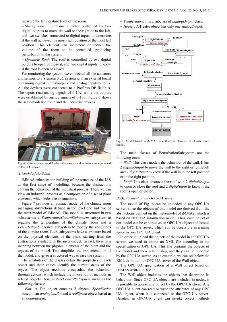
For testing our solution, a small control system forregulating the temperature of a scale modelled-room is used.This modelled-room includes the following elements: Fan. It has an actuator controlled by an analog output tospecify the speed of the fan from 0 to 100, and a sensorthrough an analog input to know the current speed of thefan in order to check the operation of the fan. Heater. It includes an actuator with an analog output toset the intensity of the heater from 0 to 100. Temperature Sensor. It includes an analog input to
7
ELEKTRONIKA IR ELEKTROTECHNIKA, ISSN 1392-1215, VOL. 23, NO. 3, 2017
measure the temperature level of the room. Slicing wall. It contains a motor controlled by twodigital outputs to move the wall to the right or to the left,and two switches connected to digital inputs to determineif the wall achieved the most right position or the most leftposition. This element can increment or reduce thevolume of the room to be controlled, producingperturbation to the system. Openable Roof. The roof is controlled by two digitaloutputs to open or close it, and two digital inputs to knowif the roof is open or closed.For monitoring the system, we connected all the actuators
and sensors to a Siemens PLC system with an external boardcontaining digital inputs/outputs and analog inputs/outputs.All the devices were connected to a Profibus DP fieldbus.The inputs read analog signals of 0-10v, while the outputswere established by analog signals of 0-10v. Figure 6 showsthe scale-modelled room and the industrial devices.
Fig. 6. Climate room model where the sensors and actuators are connectedto the PLC device.
A. Model of the PlantiMMAS enhances the building of the structure of the IAS
as the first stage of modelling, because the abstractionscontain the behaviour of the industrial process. Then, we canview an industrial process as a composition of a set of plantelements, which hides the abstractions.
Figure 7 provides an abstract model of the climate roommanaging abstractions defined in the level one and two ofthe meta-model of iMMAS. The model is structured in twosubsystems: a TemperatureControlSubsystem subsystem toregulate the temperature of the climate room and aPerturbationSubsystem subsystem to modify the conditionsof the climate room. Both subsystems have a structure basedon the physical elements of the plant, starting from theabstractions available in the meta-model. In fact, there is amapping between the physical elements of the plant and theobjects of the model. This simplifies the implementation ofthe model, and gives a structured way to face the system.
The attributes of the classes define the properties of eachobject and their values identify the current status of theobject. The object methods encapsulate the behaviourthrough actions, which include the invocation of methods inrelated objects. TemperatureControlSubsystem includes thefollowing classes: Fan: A Fan object contains 2 objects, SpeedOrderbased in an analogOutPut and a realSpeed object based inan analogInput.
Temperature: it is a subclass of analogOutput class. Heater: A Heater object has only one analogOutput.
Fig. 7. Model based in iMMAS to collect the elements of climate roomModel.
The main classes of PerturbationSubsystem are thefollowing ones: Wall: This class models the behaviour of the wall. It has2 digitalOutput to move the wall to the right or to the leftand 2 digitalInput to know if the wall is in the left positionor in the right position. Roof: This class abstracts the roof with 2 digitalOutputto open or close the roof and 2 digitalInput to know if theroof is open or closed.
B. Deployment on an OPC-UA ServerThe model of Fig. 6 can be uploaded to any OPC-UA
server, since the objects of this model are derived from theabstractions defined on the meta-model of iMMAS, which isbased on OPC UA information model. Thus, each object ofour model can be exported as an OPC-UA object and hostedto the OPC UA server, which can be accessible in a namespace by any OPC UA client.
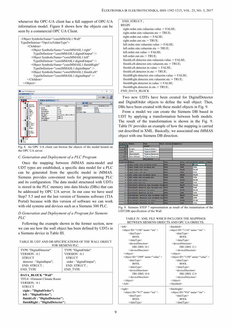
In order to upload the objects of the model in an OPC UAserver, we need to obtain an XML file according to thespecification of OPC UA. This file contains the objects ofthe model and their relationship, and they can be importedby the OPC UA server. As an example, we can see below theXML definition for OPC UA server of the Wall object.
The OPC UA specification of a Wall object based oniMMAS written in XML:
The Wall object includes the objects that determine itsbehaviour. Since OPC UA objects are included in nodes, itis possible to access any object by the OPC UA client. AnyOPC UA client can read or write the attributes of any OPCUA object, when it is connected to the OPC UA server.Besides, an OPC-UA client can invoke object methods
8
ELEKTRONIKA IR ELEKTROTECHNIKA, ISSN 1392-1215, VOL. 23, NO. 3, 2017
whenever the OPC-UA client has a full support of OPC-UAinformation model. Figure 8 shows how the objects can beseen by a commercial OPC UA Client.
Fig. 8. An OPC UA client can browse the objects of the model hosted onthe OPC UA server.
C.Generation and Deployment of a PLC ProgramOnce the mapping between iMMAS meta-model and
UDT types are established, a specific data model for a PLCcan be generated from the specific model in iMMAS.Siemens provides convenient tools for programming PLCand its configuration. The data model structured with UDTsis stored in the PLC memory into data blocks (DBs) that canbe addressed by OPC UA server. In our case we have usedStep7 5.5 and not the last version of Siemens software (TIAPortal) because with this version of software we can workwith old systems and devices such as a Siemens 300 PLC.
D.Generation and Deployment of a Program for SiemensPLC
Following the example shown in the former section, nowwe can see how the wall object has been defined by UDTs ina Siemens device in Table III.
TABLE III. UDT AND DB SPECIFICATIONS OF THE WALL OBJECTFOR SIEMENS PLC.
Two new UDTs have been created for DigitalDetectorand DigitalOrder objects to define the wall object. Then,DBs have been created with these model objects in Fig. 9.
From a model we can create the Siemens DB based inUDT by applying a transformation between both models.The result of the transformation is shown in the Fig. 9.Table IV provides an example of how the mapping is carriedout described in XML. Basically, we associated one iMMASobject with one Siemens DB direction.
Fig. 9. Siemens STEP 7 representation as result of the instantiation of theUDT/DB specification of the Wall.
TABLE IV. XML FILE WHICH INCLUDES THE MAPPINGSBETWEEN SIEMENS OBJECTS AND OPC UA OBJECTS.
<left><object ID="1106" name="sta" >
<dataType>BOOL
</dataType><deviceDirection>
DB1.DBX 10.1</deviceDirection>
</object><object ID="1098" name="value" >
<dataType>BOOL
</dataType><deviceDirection>
DB1.DBX 10.0</deviceDirection>
</object></left>
<finishleft><object ID="1116" name="sta" >
<dataType>BOOL
</dataType><deviceDirection>
DB1.DBX 12.1</deviceDirection>
</object><object ID="1198" name="value" >
<dataType>BOOL
</dataType><deviceDirection>
DB1.DBX 12.0</deviceDirection>
</object></finishleft>
<right><object ID="917" name="sta" >
<dataType>BOOL
</dataType>
<finishright><object ID="916" name="sta" >
<dataType>BOOL
</dataType>
9
ELEKTRONIKA IR ELEKTROTECHNIKA, ISSN 1392-1215, VOL. 23, NO. 3, 2017
E. Mobile HMI ClientThe tools and frameworks based on SCADA or HMI do
not support the full information model of OPC-UA model.We developed a specific HMI application that can bedeployed on smartphones and tablets with Androidecosystem [29]. The tactile native application shows thevalue of the signals of each object in a graphic fashion asFig. 10 shows.
Fig. 10. A screen capture of the HMI on which a client OPC UA isrunning in a tablet device.
Conversely, the user can settle the set-points or provokeperturbations into the system. Internally, the OPC UA clientinvokes methods on iMMAS models hosted by OPC UAserver.
V.CONCLUSIONS
OPC-UA have supposed a change of paradigm in the waythat industrial systems and industrial processes can beorganized and can be accessed by other industrial systems inan IAS. In this paper, we have presented a novel approachbased on OPC-UA, named iMMAS, which provides a simpleway to describe industrial processes as well as theorganization of the IAS, managing new basic abstractionsand concepts close to the language of industrial engineerssupported by metamodels in three layers.
On the other hand, the application of MDE principles iniMMAS opens the possibility to generate software atdifferent levels by means of the same conceptual models.These models can be executed directly facilitating itsintegration with the rest of industrial systems and providingat the same time a common data access that can be exploitedby other systems such MES. In this work we explored how aprogram for a PLC device can be built applying atransformation process to data models hosted on an OPC-UA server. This transformation process is completelyinteroperable among different manufacturers of PLC devices
as long as UDTs are known in a specific PLC solution.Furthermore, the models designed with iMMAS can be
also extended to HMI or SCADA scope, simplifying thevisualization of the models to users. As a future work wewant to improve the transformation process betweendifferent metamodels defining transformation rules thatfacilitates this process automatically.
Other important challenge to be addressed in a futurework is the behavior modeling in iMMAS, based forexample on some industrial standard for this purpose, suchas ISA 88 [28].
REFERENCES
[1] M. Hollender, Collaborative Process Automation Systems.International Society of Automation, 2010, p. 420.
[2] P. Chiacchio F. Basile, D. Gerbasio, “On the implementation ofindustrial automation systems based on PLC”, IEEE Trans. onAutomation Science and Engineering, vol. 10, no. 4, pp. 990–1003,2013. [Online]. Available: https://doi.org/10.1109/TASE.2012.2226578
[3] Programmable controllers Part 3: Programming languages. IECInternational Standard IEC 61131-3:2013. [Online]. Available:https://webstore.iec.ch/publication/4552
[4] J. Fuchs, S. Feldmann, C. Legat, B. Vogel-Heuser, “Identification ofdesign patterns for IEC 61131-3 in machine and plantmanufacturing”, in IFAC Proc. Volumes, vol. 47, no. 3, 2014,pp. 6092–6097. [Online]. Available: http://dx.doi.org/10.3182/20140824-6-ZA-1003.01595
[5] K. Thramboulidis, “A framework for the implementation of industrialautomation systems based on PLCS”, Cornell University Library,2014. [Online]. Available: https://arxiv.org/abs/1402.3920
[7] S. Yang, J. Lee, H. Kao, “Service innovation and smart analytics forindustry 4.0 and big data environment”, Procedia CIRP, vol. 16,pp. 3–8, 2014. [Online]. Available: http://dx.doi.org/10.1016/j.procir.2014.02.001
[8] M. Keller, M. Rosenberg, M. Brettel, N. Friederichsen, “Howvirtualization, decentralization and network building change themanufacturing landscape: An industry 4.0 perspective”, InternationalJournal of Mechanical, Aerospace, Industrial, Mechatronic andManufacturing Engineering, vol. 8, no. 1, pp. 37–44, 2014. [Online].Available: http://www.waset.org/publications/9997144
[9] I. Grobelna, M. Grobelny, “Logic controller design system supportinguml activity diagrams”, in 22nd Int. Conf. Mixed Design ofIntegrated Circuits & Systems (MIXDES), pp. 624–627, 2015.[Online]. Available: https://doi.org/10.1109/MIXDES.2015.7208599
[10] M. Obermeier, F. Jobst, B. Vogel-Heuser, S. Braun, K. Schweizer,“Usability evaluation on teaching and applying model-driven objectoriented approaches for PLC software”, in American Control Conf.,pp. 4463–4469, 2012.
[12] Enterprise - control system integration part 1: Models andterminology. International standard IEC 62264-1:2013. [Online].Available: https://www.iso.org/standard/57308.html
[13] Z. X. Guo, X. Q. Xie, Z. G. Ni, “The application of OPC da in factorydata acquisition”, IEEE Int. Conf. Computer Science and AutomationEngineering (CSAE), pp. 209–212, 2012. [Online]. Available:https://doi.org/10.1109/CSAE.2012.6272760
[14] M. S. Mahmoud, M. Sabih, M. Elshafei, “Using OPC technology tosupport the study of advanced process control”, ISA Trans., vol. 55,pp. 155–167, 2105. [Online]. Available: http://dx.doi.org/10.1016/j.isatra.2014.07.013
[15] J. Cabo, M. Wimmer, M. Brambilla, “Model-driven softwareengineering in practice”, Synthesis Lectures on SoftwareEngineering, Morgan & Claypool, vol. 1, pp. 1–182, 2012. [Online].Available: https://doi.org/10.2200/S00441ED1V01Y201208SWE001
[16] A. Rodrigues da Silva, “Model-driven engineering: A surveysupported by the unified conceptual model”, Computer Languages,Systems & Structures, vol. 43, no. 1, pp. 139–155, 2015. [Online].
10
ELEKTRONIKA IR ELEKTROTECHNIKA, ISSN 1392-1215, VOL. 23, NO. 3, 2017
[Online]. Available: http://www.omg.org/spec/MOF/2.4.2/[19] I. Jacobson, G. Booch, J. Rumbaugh, The unified modeling language
user guide”. Addison Wesley, 1999.[20] Omg systems Modeling language. Technology Standards
Consortium. [Online]. Available: http://www.omgsysml.org/[21] L. Bassi, C. Secchi, M. Bonfe, C. Fantuzzi, “A SysML-Based
methodology for manufacturing machinery modeling and design”,IEEE/ASME Trans. Mechatronics, vol. 16, no. 6, pp. 1049–1062,2011. [Online]. Available: https://doi.org/10.1109/tmech.2010.2073480
[22] N. Papakonstantinou, S. Sierla, “Generating an Object Oriented IEC61131-3 software product line architecture from SysML Emerging”,IEEE 18th Conf. Technologies & Factory Automation (ETFA), 2013.[Online]. Available: https://doi.org/10.1109/ETFA.2013.6648057
[23] C. Fan, Y. Chang, S. Yih, “An editing system converting a UML state
diagram to a PLC program”, Advances in Intelligent Systems &Applications, vol. 2, pp. 647–655, 2013. [Online]. Available:https://link.springer.com/chapter/10.1007/978-3-642-35473-1_64
[24] OPC DA, HDA and E&A specifications. OPC Foundation. [Online].Available: https://opcfoundation.org/
[25] OPC UA Specifications. OPC Foundation. Available: [Online].https://opcfoundation.org/
[26] W. Mahnke, L. Stefan-Helmut, M. Damm, “OPC UnfiedArchitecture”, Springer, 2009. [Online]. Available: https://doi.org/10.1007/978-3-540-68899-0
[27] Opc unified architecture. Part 3: Address space model. OPCFoundation. [Online]. Available: https://opcfoundation.org/
[28] ISA88 Batch Control. Instrument Society of America ISA. [Online].Available: https://www.isa.org/isa88/
[29] J. Gutierrez-Guerrero, J. A. Holgado-Terriza, “Mobile humanmachine interface based in OPC UA for the control of industrialprocesses”, Actas de las XXXVI Jornadas de Automatica, pp. 1073–1080, 2015. [Online]. Available: http://www.ehu.eus/documents/3444171/4484750/ 154.pdf


![Sustainability Report - Siemens Gamesa...4 / 69 1. About this Report 1.1 Scope of the Report [102-49] [102-50] On April 3,2017, the merger of Siemens Wind Power Business with GAMESA](https://static.documents.pub/doc/80x56/5ed0ee44ae76547b173cdaa3/sustainability-report-siemens-gamesa-4-69-1-about-this-report-11-scope.jpg)


