Page 1
IMMEDIATE CHANGE IN STABILITYAND VOLTAGE COLLAPSE
WHEN POWER SYSTEM LIMITSARE ENCOUNTERED
by
LIMING LU
A thesis submitted in partial fulfillment of the
requirements for the degree of
Master of Sciences
(Electrical and Computer Engineering)
at the
UNIVERSITY OF WISCONSIN—MADISON
1991
Page 2
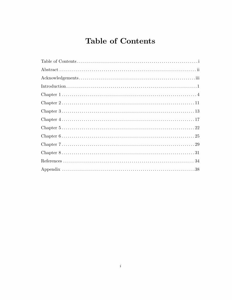
Table of Contents
Table of Contents . . . . . . . . . . . . . . . . . . . . . . . . . . . . . . . . . . . . . . . . . . . . . . . . . . . . . . . . . . . . i
Abstract . . . . . . . . . . . . . . . . . . . . . . . . . . . . . . . . . . . . . . . . . . . . . . . . . . . . . . . . . . . . . . . . . . . . ii
Acknowledgements . . . . . . . . . . . . . . . . . . . . . . . . . . . . . . . . . . . . . . . . . . . . . . . . . . . . . . . . . . iii
Introduction . . . . . . . . . . . . . . . . . . . . . . . . . . . . . . . . . . . . . . . . . . . . . . . . . . . . . . . . . . . . . . . . .1
Chapter 1 . . . . . . . . . . . . . . . . . . . . . . . . . . . . . . . . . . . . . . . . . . . . . . . . . . . . . . . . . . . . . . . . . . . 4
Chapter 2 . . . . . . . . . . . . . . . . . . . . . . . . . . . . . . . . . . . . . . . . . . . . . . . . . . . . . . . . . . . . . . . . . . 11
Chapter 3 . . . . . . . . . . . . . . . . . . . . . . . . . . . . . . . . . . . . . . . . . . . . . . . . . . . . . . . . . . . . . . . . . . 13
Chapter 4 . . . . . . . . . . . . . . . . . . . . . . . . . . . . . . . . . . . . . . . . . . . . . . . . . . . . . . . . . . . . . . . . . . 17
Chapter 5 . . . . . . . . . . . . . . . . . . . . . . . . . . . . . . . . . . . . . . . . . . . . . . . . . . . . . . . . . . . . . . . . . . 22
Chapter 6 . . . . . . . . . . . . . . . . . . . . . . . . . . . . . . . . . . . . . . . . . . . . . . . . . . . . . . . . . . . . . . . . . . 25
Chapter 7 . . . . . . . . . . . . . . . . . . . . . . . . . . . . . . . . . . . . . . . . . . . . . . . . . . . . . . . . . . . . . . . . . . 29
Chapter 8 . . . . . . . . . . . . . . . . . . . . . . . . . . . . . . . . . . . . . . . . . . . . . . . . . . . . . . . . . . . . . . . . . . 31
References . . . . . . . . . . . . . . . . . . . . . . . . . . . . . . . . . . . . . . . . . . . . . . . . . . . . . . . . . . . . . . . . . 34
Appendix . . . . . . . . . . . . . . . . . . . . . . . . . . . . . . . . . . . . . . . . . . . . . . . . . . . . . . . . . . . . . . . . . .38
i
Page 3
Abstract
Voltage collapse is a loss of stability in large scale electric power systems
which causes blackout when voltages decrease catastrophically. Voltage collapse
is generally associated with bifurcation of the nonlinear power system equations;
that is, the disappearance as parameters vary of the stable equilibrium at which
the power system is normally operated. System limits such as generator reactive
power limits and tapchanging transformer limits are thought to be important in
voltage collapse. This thesis studies the statics and dynamics of power system by
example and by the generic theory of saddle node and transcritical bifurcations.
When a generator of a heavily loaded electric power system reaches a reactive
power limit, the system can become immediately unstable and a dynamic voltage
collapse leading to blackout may follow. Load power margin calculations can be
misleading if the immediate instability phenomenon is neglected. The dynamics
of voltage collapse were illustrated using an example power system. But when
locking a tapchaging transformer, the system can become more stable.
All the power system computations have been done using the numeric and
symbolic capabilities of the Mathematica computer algebra package.
This thesis has been done under the supervision of Professor Ian Dobson.
ii
Page 4
Acknowledgements
I am indebted to my advisor, Ian Dobson, for inspiring me to pursue a career
in power system stability analysis and teaching me to think before I compute. I
wish to thank his warm support throughout my graduate school “career”. I am
proud to be his first graduated student.
I am also grateful to the power system group for making my short study at
University of Wisconsin-Madison such a wonderful experience.
I would like to thank my parents for encouraging me to continue study in
graduate school.
I gratefully acknowlege support in part from NSF under grant number ECS-
9009079.
iii
Page 5
1
Introduction
Voltage collapse is an instability of heavily loaded electric power systems
which leads to declining voltages and blackout. It is associated with bifurcation
and reactive power limitations of the power system. Power systems are expected
to become more heavily loaded in the next decade as the demand for electric
power rises while economic and environmental concerns limit the construction
of new transmission and generation capacity. Heavily loaded power systems are
closer to their stability limits and voltage collapse blackouts will occur if suitable
monitoring and control measures are not taken. It is important to understand
mechanisms of voltage collapse so that voltage collapse blackouts may be effec-
tively prevented. Most of the current approaches to analyzing voltage collapse
are represented in [6].
Voltage collapses are infrequent but catastrophic. One of the examples is the
power system failure which occurred on July 23, 1987 in Tokyo, Japan. As the
power demand increased, voltage began to fall in spite of the shunt capacitors,
resulting in the voltage collapse which eventually caused the major power failure
affecting a wide area. The voltage collapse led to the power outage of 8,168 MW
and affected about 2.8 million customers in the area.
Voltage collapse is associated with bifurcation of the equations representing
the power system. These equations are nonlinear and have multiple solutions
which vary as system parameters such as load demand vary. As these parame-
ters are varied, changes may occur in the qualitative structure of the solutions for
certain parameter values. These changes are called bifurcations and the parame-
ter values are called bifurcation values. If one of these solutions corresponded to
the stable operating point of the power system, the bifurcation causes the system
to lose stability and a dynamic voltage collapse follows.
Page 6
2
Some explanations of voltage collapse involve generator reactive power out-
put and tap changing transformers reaching limits and the research needs to
address the limits which become applicable as voltage collapse is approached.
One aspect is that power systems become more vulnerable to voltage collapse
when generator reactive power limits are encountered [7 - 13]. The effect of a
generator reactive power limit is to immediately change the system equations. For
example, the effect of a generator excitation current limit may be simply modelled
by replacing the equation describing a constant output voltage magnitude by an
equation describing a constant excitation current. Although the system state is
unchanged, the immediate change in the system equations causes a discontinuous
change in the stability margin of the system. The case in which the stability
margin decreases when the reactive power limit is encountered but the system
remains stable is familiar [7,10,14,12,11]. We study the case in which the system
becomes immediately unstable when the reactive power limit is encountered.
This possibility was mentioned by Borremans et al [9] but otherwise appears
to have been overlooked. The immediate instability of the system can lead to
voltage collapse and the main purpose of this thesis is to study the statics and
dynamics of this mechanism for voltage collapse.
We analyze a power system example and demonstrate that at lesser loadings,
encountering the reactive power limit is expected to decrease, but not destroy
stability. At sufficiently high loadings, encountering the reactive power limit will
immediately destabilize the system and can precipitate a voltage collapse along
a trajectory which is one part of the unstable manifold of an unstable equilib-
rium. The movement along this trajectory is a new model for the dynamics of
voltage collapse. Moreover we can argue using the theory of saddle node and
transcritical bifurcations that the immediate instability and subsequent dynamic
voltage collapse are likely to be typical for a general, heavily loaded power system.
The results have important implications for correctly measuring the proximity
Page 7
3
to voltage collapse using load power margins; it seems that the load power mar-
gin to bifurcation can be a misleading indication of system stability unless the
possibility of immediate voltage collapse is taken into account.
Another aspect is that power systems become more stable when we lock
tapchanger ratios. The effect of the tapchanger limit may be simply modelled
by replacing tapchanger ratio n by a constant nlim in system equations. The
system changes structure by losing one degree of freedom. We give an example
in which locking the tapchanger makes the system more stable.
Some of the material in this thesis will appear in [1]. Other research related
to this thesis included how system loads, parameters and controls contribute to
voltage collapse. The knowledge of the normal vector to a hypersurface yields the
best direction in parameter space to move away from the hypersurface and thus
an optimal increase in the system security. We can use the formula for the normal
vector to derive algorithms for computing the critical voltage collapse loadings
closest to the operating load powers [3]. A direct method and an iterative method
to compute the load powers at which bifurcation occurs and are locally closest
to the current operating load powers have been developed and tested on a 5 bus
power system [2, 4]. We have also discussed another author’s paper about the
calculation of the extreme loading condition of a system [5].
Page 8
4
Chapter 1
Basic Principles ofInvariant Manifolds and Bifurcations
This section states some basic concepts about the theory of generic bifurca-
tion and invariant manifolds for nonlinear dynamical systems. The knowledge of
this section is covered in [21, 22].
Suppose a nonlinear dynamical system is defined by the differential equation:
x = f(x, λ) x ∈ Rn, λ ∈ Rm (1.1)
where x is a vector of state variables and λ is a vector of parameters. A point
x0 is called an equilibrium point of (1.1) if f(x0, λ0) = 0. The eigenvalues of
the Jacobian matrix evaluated at an equilibrium point usually determine the
dynamic behavior in the neighborhood of the equilibrium. The equilibrium is
called hyperbolic or nondegenerate when the Jacobian has no eigenvalue with
zero real part.
An invariant manifold W of a system x = f(x) is a manifold in the state
space with the property that for any initial vector x in W , the associated tra-
jectory φ(t, x) stays in W for all t; that is, an invariant manifold is composed of
flow lines.
The unstable manifold Wu(x0) of an equilibrium point x0 is the manifold
in the state space from which trajectories converge to x0 as t → −∞ and which
is tangent at x0 to the subspace spanned by the eigenvectors associated with
eigenvalues with positive real parts.
The stable manifold W s(x0) of an equilibrium point x0 is the manifold in the
state space from which trajectories converge to x0 as t → ∞ and which is tangent
Page 9
5
at x0 to the subspace spanned by the eigenvectors associated with eigenvalues
with negative real parts.
There exists another invariant manifold, called the center manifold W c(x0),
which is tangent to the subspace spanned by the eigenvectors associated with the
eigenvalues on the imaginary axis.
The system x = f(x, λ) depend on the parameter λ. Solutions now depend
both on the independent variable t and on λ. Consequently, equilibrium points,
Jacobian matrices at the equilibrium points, and the eigenvalues µ depend on
λ. Upon varying the parameter λ, the position and the qualitative features
of a equilibrium point can vary. For example, we choose an eigenvalue µ and
imagine a stable focus Re[µ(λ)] < 0 for some values of λ. When λ passes some
critical value λ∗, Re[µ(λ)] may change sign and the equilibrium point may turn
into an unstable focus. Often, qualitative changes such as a loss of stability are
encountered when a degenerate case is passed since the eigenvalues are continuous
function of parameters.
A commonly encountered nonlinear phenomena is bifurcation in which
several equilibria interact. If a system is described by differential equations
x = f(x, λ), the necessary conditions. for the bifurcation at (x∗, λ∗) are
f(x∗, λ∗) = 0 and the Jacobian Df |(x∗,λ∗) has a zero eigenvalue. (If the Ja-
cobian is nonsingular, then the implicit function theorem implies that there is
no bifurcation in which several equilibria interact.) We describe three types
of bifurcation: Saddle node bifurcation, transcritical bifurcation and pitchfork
bifurcation.
(1) Saddle node bifurcation:
Saddle node bifurcation occurs when the parameters vary so that two of
the multiple solutions of nonlinear equations approach each other, coalesce, and
finally disappear.
Page 10
6
A typical saddle node bifurcation has transversality conditions: ∂2f∂x2
∣∣x∗ �= 0
and ∂f∂λ
∣∣x∗ �= 0. Usually, a saddle node bifurcation is generic which means the
set of one parameter systems with a typical saddle node bifurcation is dense and
open. Density means that we can perturb f(x, λ) to be a typical saddle node,
and openness means that if we have a typical saddle node and we perturb it
sufficiently slightly, the system also has a typical saddle node.
To understand the general theory of the saddle node bifurcation, we present
the simplest example of x ∈ R, λ ∈ R. Assume an equilibrium at zero. We
expand system function by using a Taylor series at x = 0:
f(x, λ) = f(0, 0) + xfx + λfλ +12x2fxx + xλfxλ +
12λ2fλλ + h.o.t. (1.2)
Using conditions for a saddle node bifurcation and neglecting high order terms
by assuming small x, λ we have
f(x, λ) = λfλ +12x2fxx
which can be written as
f(x, λ) = ax2 + bλ = 0
The transversality condition ensure that a and b are nonzero. The bifurcation
diagrams near (0, 0) are given by λ = −ab x2 shown as figure(1). A saddle node
bifurcation contains parameter values for which there are no equilibria near the
point of bifurcation (two solutions disappear after bifurcation).
Page 11
7
Figure 1 : saddle node bifurcation diagram
(2) Transcritical bifurcation:
Transcritical bifurcation occurs when the parameters vary so that two of the
solutions approach each other, coalesce, and then separate with an exchange of
stability.
Saddle node bifurcation are typical in a generic system. However if we
assume a system satisfies f(x∗, λ∗) = 0 and f(x∗, λ) = 0 for all λ, then x = x∗
is a equilibrium for all parameter values. This is totally different from a saddle-
node bifurcation. If we impose the conditions: ∂2f∂x∂λ
∣∣x∗,λ∗ �= 0 and ∂2f
∂x2
∣∣x∗ �= 0, we
have a transcritical bifurcation. The expanded system function (3.2) at x = 0
can be written as
f(x, λ) =12x2fxx + xλfxλ = ax2 + bxλ
The solutions are x = 0 and x = −ab λ. The transcritical bifurcation diagram is
shown in figure(2).
Page 12
8
Figure 2 : Transcritical bifurcation diagram
(3) Pitchfork bifurcation:
Pitchfork bifurcation occurs in system with a symmetry when the parameters
vary so that one of the solutions changes stability and a new pair of equilibria
(related by symmetry) appear to one side of the point of bifurcation in parameter
space.
If a system satisfies f(x∗, λ∗) = 0 and f(x∗, λ) = 0 for all λ, and also it
is an odd function, a transcritical bifurcation cannot occur because ∂2f∂x2
∣∣x∗= 0.
But another condition may be satisfied: ∂3f∂x3
∣∣x∗ �= 0. Then the expanded system
function at x = 0 can be written as
f(x, λ) =f(0, 0) + xfx + λfλ +12x2fxx + xλfxλ +
12λ2fλλ
+16x3fxxx +
12x2λfxxλ +
12xλ2fxλλ +
16λ3fλλλ + h.o.t.
By imposing the conditions above, we have
f(x, λ) = xλfxλ +16x3fxxx = ax3 + bxλ
the solutions are x = 0 and x2 = − baλ. This is a pitchfork bifurcation. The
bifurcation diagram is shown in figure 3 (a) & (b). If ba < 0, it is a supercritical
bifurcation like (a). If ba > 0, it is a subcritical bifurcation like (b).
Page 13
9
Fiure 3(a) : supercritical pitchfork bifurcation
Fiure 3(b) : subcritical pitchfork bifurcation
Page 14
10
Another kind of bifurcation is Hopf bifurcation. In the generic Hopf bifur-
cation, the equilibrium changes stability by interacting with a limit cycle. The
Jacobian has a single, simple pair of imaginary eigenvalues at the bifurcation.
We will not discuss the detail of this kind of bifurcation. More knowledge about
it can be obtained from [21, 22].
In power systems, when we discuss the bifurcation with respect to the volt-
age collapse, usually we do not expect that pitchfork bifurcation or transcritical
bifurcation occurs because power system models are usually not symmetric and
equilibria are not usually fixed but always change with the parameters.
Page 15
11
Chapter 2
Power System Model
This section summarizes the 3 bus power system example of [15,16] (see
figure 4) which consists of two generators (one is slack bus), a dynamic load with
capacitative support and a tapchanging transformer. The model is that of [15]
with the addition of the tapchanging transformer. We assume the tap ratio n of
the tapchanging transformer is unity except in section 6 where the tapchanging
transformer dynamics and limits are considered. The parameter values used in
this paper are identical to those of [15,16] except that the generator damping D
has been increased. This eliminates the Hopf bifurcations and other oscillatory
phenomena discovered in [17,18] at high loadings. A well designed power system
stabilizer would suppress these oscillations. Note that the value of D has no
effect on the loading at which the saddle node bifurcation occurs.
The load model includes a dynamic induction motor model with a constant
PQ load in parallel. The combined model for the motor and the PQ load is
Pl =P0 + P1 + Kpw δ + Kpv(V + T V ) (2.1)
Ql =Q0 + Q + Kqw δ + KqvV + Kqv2V2 (2.2)
Q is a parameter which varies with the load reactive power demand. The ca-
pacitor is accounted for by adjusting E0, Y0 and θ0 to E′0, Y ′
0 and θ′0 to give the
Thevenin equivalent of the circuit with the capacitor.
The system can be described by following differential equations [15]
δm = ω (2.3)
Mω = − Dω + Pm +EmYmV
nsin(δ − δm − θm) + E2
mYm sin θm(2.4)
Kqw δ = − Kqv2V2 − KqvV + Ql − Q0 − Q (2.5)
TKqwKpvV =KpwPqv2V2 + (KpwKqv − KqwKpv)V
+ Kqw(Pl − P0 − P1) − Kpw(Ql − Q0 − Q) (2.6)
Page 16
Eo 0
Yo
Load
Ym
n:1
X
E
s
V o Em mo
C
12
where the real and reactive powers supplied to the load by the network are
Pl = − E′0Y
′0V sin(δ + θ′0) −
EmYmV
nsin(δ − δm + θm)
+ (Y ′0 sin θ′0 +
Ym sin θm
n2)V 2 (1.7)
Ql = E′0Y
′0V cos(δ + θ′0) +
EmYmV
ncos(δ − δm + θm)
− (Y ′0 cos θ′0 +
Ym cos θm
n2)V 2 (1.8)
Em is the terminal voltage of the generator and E is the internal voltage of the
generator.
The state vector is x = (δm, ω, δ, V ) and M , D and Pm are the generator
inertia, damping and mechanical power respectively. The load parameter values
are Kpw = 0.4, Kpv = 0.3, Kqw = −0.03, Kqv = −2.8, Kqv2 = 2.1, T = 8.5,
P0 = 0.6, Q0 = 1.3, P1 = 0.0 and the network and generator parameter values
are Y0 = 20.0, θ0 = −5.0, E0 = 1.0, C = 12.0, Y ′0 = 8.0, θ′0 = −12.0, E′
0 = 2.5,
Ym = 5.0, θm = −5.0, Em = 1.0, Pm = 1.0, D = 0.12, M = 0.3, Xs = 0.15.
Fiure 4 : 3 − bus example power system
Page 17
13
Chapter 3
Model of the Generator Q-Limit
The two main causes of the reactive power output Qg reaching limit in a
generator are the excitation current limit and the stator thermal limit [19, 20],
shown in figure 5.
Figure 5 : Generator reactive power limit curve
The two limits have similar overall effects on the system and we only con-
sider the excitation current limit (rotor limit). For any round rotor generator
connected to an infinite bus in shown figure 6(a), we can draw a phasor diagram
like figure 6(b).
Page 18
14
Figure 6(a) : Generator connected to an infinite bus
Figure 6(b) : Phasor diagram
Here Em is the terminal voltage of the generator, E is the internal voltage of the
generator, δ is the angle between E and Em, φ is the angle between I and Em,
xs is synchronous reactance and I is current.
From figure 6(b):
IXs cos φ = E sin δ
⇒ Pg = EmI cos φ =EEm
Xssin δ
IXs sin φ + Em = E cos δ
⇒ Qg = EmI sin φ =EEm
Xscos δ − E2
m
Xs
Page 19
15
Because the generator internal voltage E is proportional to the excitation current,
the excitation current limit may be modelled by E encountering a limit Elim.
Before the limit is encountered, E < Elim and Em is controlled so that Em =
Eimpm , the terminal voltage imposed by the regulator [10]. When the limit is
encountered, E = Elim and Em varies with Em < Eimpm . Encountering the
limit may be thought of as changing from the constraint of constant Em to
the constraint of constant E. The effect of the limit on the system differential
equations (2.3)-(2.6) is to replace the constant Em by an expression involving
the system state and Elim. We now derive the necessary equations for this
replacement.
Write the powers delivered to the network by the generator as:
Pg =EEmYs sin δs (3.1)
Qg =EEmYs cos δs − E2mYs (3.2)
where δs is the difference of the angle between E and Em and Ys is 1/Xs. Squar-
ing and adding (3.1) and (3.2) yields
(Qg + E2
mYs
)2+ P 2
g = (EEmYs)2 (3.3)
Real and reactive power balance at the generator gives
Pg = − E2mYm sin θm + EmYmV sin(δm − δ + θm) (3.4)
Qg = E2mYm cos θm − EmYmV cos(δm − δ + θm) (3.5)
A quadratic equation in Em can be obtained from (3.3) to (3.5):
E2m(Ym cos θm + Ys)2 − 2EmYmV (Ym cos θm + Ys) cos(δm − δ + θm)
+Y 2mV 2 cos2(δm − δ + θm) + E2
mY 2m sin2 θm − 2EmY 2
mV sin θm sin(δm − δ + θm)
Page 20
16
+Y 2mV 2 sin2(δm − δ + θm) − E2Y 2
s = 0 (3.6)
The limited system equations are obtained by solving (3.6) with E replaced
by Elim for the positive solution of Em and substituting it into (2.3)-(2.6). It
remains to compute the value of Elim. Suppose Qg reaches its limit at Q = Qlim.
Then Elim is computed from equations (3.3)-(3.5) where δm, δ, V are equilibrium
solutions of (2.3)-(2.6) when Q = Qlim.
Page 21
17
Chapter 4
Immediate Voltage Collapsewhen a Limit is Encountered
We present two cases of the example power system encountering an excita-
tion current limit. It is convenient to write J for the Jacobian of the unlimited
system evaluated at the operating equilibrium x0 and J lim for the Jacobian of
the limited system evaluated at x0. The first case is well known and the bifur-
cation diagrams of the unlimited and limited systems are shown in figure 7(a).
The limit is encountered at Q = Qlim = 11.0. When the limit is encountered
the system changes structure and J changes to J lim. The eigenvalues of J lim
differ from the eigenvalues of J but their real parts remain negative (see table 1,
case (a)). The equilibrium at x0 of the limited system has reduced stability but
remains stable and the system reactive power margin Q∗−Qlim is reduced. Note
that the upper portion of each of the bifurcation diagrams is stable and the lower
portion is unstable; in this case x0 is on the upper and stable portion of both
the unlimited and limited system bifurcation curves.
In the second case, the limit is encountered at the higher system loading
Q = Qlim = 11.4. The system changes so that J lim has an eigenvalue with
positive real part (see table 1, case(b)). In this case x0 is on the upper and stable
portion of unlimited system bifurcation curve and the lower and unstable portion
of limited system bifurcation curve (see figure 7(b)). The operating equilibrium
x0 becomes immediately unstable when the limit is encountered and the system
dynamics will move the system state away from x0. Now we describe the dynamic
consequences of the instability; see [21,22] for background in dynamical systems
and bifurcations.
Page 22
18
Figure 7(a). Limit encountered at a lesser loading
Figure 7(b). Immediate instability when limit is encountered
Page 23
19
Table 1
The unstable equilibrium x0 has a one dimensional unstable manifold Wu
which consists of two trajectories Wu− and Wu
+ leaving x0 and x0 itself (see the
idealized sketch of figure 8). Wu is a smooth curve passing through x0 which is
tangent at x0 to the eigenvector v of J lim associated with the positive eigenvalue.
x0 also has a three dimensional stable manifold W s which divides the state space
near x0 into two parts. Note that the stable manifolds sketched in figure 8 have
an additional dimension which is not shown.
Figure 8. Idealized sketch of limited system dynamics
Page 24
20
The system state is initially at x0 but cannot remain there because of the
inevitable small perturbations on the state. If the state is perturbed from x0 to
one side of W s, it will be attracted towards Wu− and we can simply approximate
the dynamics by motion along Wu−. Similarly, if the state is perturbed from x0
to the other side of W s, it will be attracted towards Wu− and we can simply
approximate the dynamics by motion along Wu−. In short, the dynamical conse-
quences of the immediate instability are motion along the trajectory Wu− or the
trajectory Wu+. Either outcome is possible and there seems no reason to regard
Wu− or Wu
+ as more likely.
We integrated the differential equations of the limited system starting near
x0 to find the outcome of motion along Wu− or Wu
+. (The initial conditions were
chosen to be x0±0.001v and the Gear (stiff) ordinary differential equation solver
in NAG Fortran Library Routines [23] was used since differential equations are
stiff near a saddle node bifurcation.) The corresponding time histories of V are
shown in figure 9. The trajectory Wu− tends to the nearby stable equilibrium xlim
1
and the initial portion of the slow, oscillatory convergence of V to xlim1 is shown in
the upper graph of figure 9. (This may not occur in practice because the voltage
control system could prevent the voltage from rising [14].) The trajectory Wu+
diverges so that V decreases and the motion along Wu+ shown in the lower graph
of figure 9 is a voltage collapse. Thus we describe a model of a new mechanism
for voltage collapse:
The operating equilibrium x0 becomes immediately unstable when a reactive
power limit is encountered and one of the possible dynamical consequences is
voltage collapse along part of the unstable manifold of x0.
This model of immediate voltage collapse has some similarities with the cen-
ter manifold collapse model [15]; the voltage collapse dynamics can be modelled
by movement along a particular trajectory. However, the trajectory is part of an
unstable manifold instead of the unstable part of a center manifold and there is
Page 25
21
also the possibility of convergence to a nearby stable equilibrium along the other
part of the unstable manifold.
Figure 9. Possible dynamics caused by immediate instability
Page 26
22
Chapter 5
Approximate analysis showing that immediatevoltage collapse can occur for high loading
We expect the immediate instability of our example to be typical for suffi-
ciently high loadings. This can be demonstrated analytically by approximating
the equations of the example system as follows. First consider the relationship
between V , E and Em. Write α = δm − δ, and approximate the line impedance
to be purely reactive so that θm = 0. Equation (3.6) becomes
E2m(Ym + Ys)2 − 2EmYmV (Ym + Ys) cos α + Y 2
mV 2 − E2Y 2s = 0 (5.1)
Assuming that α is small (≤ 20◦), we approximate cos α ≈ 1, and write Y ′m =
Ym + Ys to obtain the reduced equation:
Em =EYs
Y ′m
+YmV
Y ′m
(5.2)
We substitute (5.2) into system differential equations (2.5) and get a decoupled
dynamical equation for the limited system with the left hand side set to zero:
Q0 + Q −(−Kqv + E′
0Y′0 cos δ +
EYmYs
Y ′m
cos α
)V
+(
Kqv2 + Y ′0 + Ym − Y 2
m
Y ′m
cos α
)V 2 = 0 (5.3)
Using the approximations of [16], we suppose all angles are small:
Q0 + Q −(−Kqv + E′
0Y′0 +
EYmYs
Y ′m
)V +
(Kqv2 + Y ′
0 + Ym − Y 2m
Y ′m
)V 2 = 0
(5.4)
Page 27
23
Equation (5.4) describes the bifurcation curve (the relation between V and Q)
of the limited system as shown in figure 7(b). The gradient of (5.4) is
dQ
dV= −Kqv + E′
0Y′0 +
EYmYs
Y ′m
− 2V
(Kqv2 + Y ′
0 + Ym − Y 2m
Y ′m
)(5.5)
For comparison, we write the equation of the bifurcation curve for the unlimited
system as [16]:
Q0 + Q − (−Kqv + E′0Y
′0 + EmYm)V + (Kqv2 + Y ′
0 + Ym) V 2 = 0 (5.6)
The gradient of (5.6) is
dQ
dV= −Kqv + E′
0Y′0 + EmYm − 2V (Kqv2 + Y ′
0 + Ym) (5.7)
At the intersection of two curves, we can substitute (5.2) into (5.5). Then (5.5)
becomes:
dQ
dV= − Kqv + E′
0Y′0 + EmYm − 2V (Kqv2 + Y ′
0 + Ym) + VY 2
m
Y ′m
(5.8)
Comparing (5.7) and (5.8), it is clear that the gradient of the bifurcation curve of
the unlimited system is always larger than the gradient of the bifurcation curve
of the limited system at their intersection since V Y 2m/Y ′
m is always positive.
Now suppose the limit is encountered at the saddle node bifurcation of the
unlimited system so that Qlim = Q∗, the value of Q at the saddle node bifurca-
tion. For the unlimited system we have the gradient dQdV |V∗ = 0 at the saddle node
bifurcation point where V∗ is the voltage at the saddle node bifurcation. For the
limited system, it follows that dQdV |V∗ > 0 and hence dV
dQ |Q∗ > 0. Therefore the two
curves cross each other at the bifurcation point as shown in figure 10. Because
the lower portion of the curve is unstable, the equilibrium x0 becomes unstable
and J lim has a positive eigenvalue when the limit Qlim = Q∗ is encountered.
Now we suppose that the limit is encountered at a loading Qlim less than
and close to Q∗. Since the eigenvalue of J lim is a continuous function of Qlim,
we conclude that the equilibrium x0 will become immediately unstable when the
limit is encountered for Qlim sufficiently close to Q∗.
Page 28
24
Figure 10. Immediate instability at a saddle node bifurcation
Page 29
25
Chapter 6
Immediate instability and voltage collapsein a general power system model
The particular example presented above shows that a sufficiently heavily
loaded but stable system can become immediately unstable when a reactive power
limit is encountered. The dynamical consequences of this instability are either
collapse along the unstable manifold trajectory Wu+ or convergence to a nearby
stable equilibrium along the unstable manifold trajectory Wu−. Now we argue that
this description is expected to apply in the general case. Our main assumptions
are that applying a reactive power limit does not increase the margin of system
stability, the phenomena occurring are generic and a simplification that only one
bifurcation occurs.
Consider a general power system modelled by smooth parameterized differ-
ential equations x = f(x, λ), where x ∈ Rn is the system state and λ ∈ Rm are
slowly changing system parameters such as real and reactive load powers [15].
We suppose the system is operated at a stable equilibrium x0 when the param-
eters are λ0. When a reactive power limit is encountered the system equations
immediately change to x = f lim(x, λ) but the position of the equilibrium x0 is
unchanged. That is, 0 = f(x0, λ0) = f lim(x0, λ0).
Now suppose that the equations x = f(x, λ) are gradually changed into the
equations x = f lim(x, λ). This can easily be done by combining f and f lim into
new equations
x = g(x, λ0, k) (6.1)
with a parameter k so that g(x, λ0, 0) = f(x, λ0) and g(x, λ0, 1) = f lim(x, λ0).
We also require that
g(x0, λ0, k) = 0 for k ∈ [0, 1] (6.2)
Page 30
26
In short, we construct a homotopy joining f and f lim which preserves the equilib-
rium at x0. Note that λ is fixed at λ0 as the parameter k is varied. k gradually
increasing from 0 to 1 has the effect of gradually applying the reactive power
limit to the system. This allows the change in structure between f and f lim to
be studied using bifurcation theory. However, we do not seek to represent the
manner in which the reactive power limit is applied in practice by the gradual
increase in k.
(6.1) is a one parameter system of differential equations with the restriction
(6.2) of an equilibrium at x0. If we assume that this is a generic one parame-
ter system of differential equations, then the only bifurcations which can occur
are the transcritical bifurcation and the Hopf bifurcation [21]. (In the set of all
smooth one parameter differential equations without restrictions or symmetries,
the generic bifurcations are the saddle node bifurcation and the Hopf bifurca-
tion. An equilibrium disappears in a saddle node bifurcation and therefore the
restriction (6.2) precludes saddle node bifurcations.) In a generic transcritical
bifurcation two equilibria approach each other, coalesce and then separate with
an exchange of stability. The Jacobian has a single, simple zero eigenvalue at the
bifurcation. If one of the equilibria is stable before the bifurcation, then the other
is type one unstable. After the bifurcation the equilibria are also stable and type
one unstable but each equilibrium has changed its stability. Figure 11 shows a
typical bifurcation diagram for the transcritical bifurcation in which the solid line
indicates stable equilibria and the dashed line denotes unstable equilibria. In the
generic Hopf bifurcation, the equilibrium changes stability by interacting with
a limit cycle. The Jacobian has a single, simple pair of imaginary eigenvalues
at the bifurcation. Of course it is also generic for there to be no bifurcation for
k ∈ [0, 1].
We first consider the special case of encountering a reactive power limit at the
point of voltage collapse; that is, λ0 is chosen so that x = f(x, λ) with parameter
Page 31
27
λ has a generic saddle node bifurcation at (x0, λ0). Then x0 is a degenerate
equilibrium formed by the coalescence of a stable equilibrium and a type one
unstable equilibrium and the Jacobian of f evaluated at (x0, λ) is singular [15].
Since the Jacobian of f evaluated at (x, λ0) and the Jacobian of g evaluated at
(x, λ0, 0) are identical, the Jacobian of g evaluated at (x, λ0, 0) is also singular.
Therefore (x0, λ0, 0) is also a bifurcation point of the system (6.1) with k as
parameter. If we consider only generic phenomena, then the bifurcation of (6.1)
at (x0, λ0, 0) is a transcritical bifurcation. The Hopf bifurcation is precluded by
the single zero eigenvalue and absence of nonzero imaginary eigenvalues of the
Jacobian at x0 at the generic saddle node bifurcation of x = f(x, λ) with λ as
parameter.
In a generically occuring transcritical bifurcation the bifurcation diagram
(suitably reduced to the center manifold of the suspended system [22]) is as
shown in figure 11. There are two possible “directions” through the bifurcation
as k is increased from zero so that the equilibrium x0 is either stable or unstable
for small positive k. Since reactive power limits are generally observed to limit
system performance, it seems likely that partially applying a reactive power limit
(imposing small positive k) should destabilize rather than stabilize the system.
Thus the more usual case to consider should be x0 unstable for small positive k.
For small positive k there is a type one unstable equilibrium x1 close to x0 and
part of the unstable manifold Wu− of x0 is a trajectory tending to x1. In this
case, if we further assume for simplicity that there are no further bifurcations
as k increases from a small positive value to one, then we can conclude that at
k = 1, the system x = g(x, λ0, 1) = f lim(x, λ0) has x0 unstable and type one.
Moreover, there is a stable equilibrium x1 in the vicinity and the part Wu− of the
unstable manifold of x0 is a trajectory tending to x1.
The assumption of genericity of the one parameter differential equations
(6.1) implies that the occurence of the transcritical bifurcation is robust to small
Page 32
28
changes in (6.1). In particular, if we consider a sufficiently heavily loaded but
still stable system f(x, λ′0) with λ′
0 chosen close to λ0 so that f(x, λ′0) has a
stable equilibrium x′0, then the corresponding homotopy g(x, λ′
0, k) will have
a transcritical bifurcation as k increases from zero to one and we can extend
the conclusions for the case of a reactive power limit encountered at the saddle
node bifurcation to the case of a reactive power limit encountered just before the
saddle node bifurcation. The only difference is that x0 is stable for k = 0 and the
transcritical bifurcation will occur at a positive value of k. Figure 11 shows the
bifurcation diagram for the change in stability of the example system in case (b)
(the black circles are the data we computed).
Figure 11. Transcritical bifurcation diagram when limit is gradually applied
Page 33
29
Chapter 7
Locking the Tap-Changing Transformercan Improve the System Stability
Liu and Vu [13] describe examples in which locking the tap ratios of
tapchanging transformers can improve the system stability and avoid voltage
collapse. We show how locking a tap ratio n can be described as the dynamic
variable n encountering a limit nlim and confirm the results of [13] in our exam-
ple power system. Note that the tap ratio may also encounter a limit when the
maximum or minimum tap setting is reached. A typical range for a tapchanger
tap ratio is 10% of the nominal value of n.
To consider dynamics of the tapchanging transformer we include the tap
ratio n in the state vector and add the following tapchanging dynamics to the
differential equations (2.3)-(2.6) [25]:
n =1Ts
(Vs − V ) (6.1)
Since a step in tap position typically changes the voltage in small increments
(e.g. 0.625 percent of the nominal voltage [13]), using a continous tapchanging
transformer model instead of a discrete model is practically acceptable. In (6.1),
Ts is the time constant and Vs is the reference voltage. We use Ts = 2.0 and
Vs = 1.0.
The effect of the n encountering the limit nlim is that n is set to the constant
value nlim and equation (6.1) is omitted. Thus the system changes structure by
losing one degree of freedom; the state vector dimension and the number of
differential equations are reduced by one. The operating equilibrium when the
limit is encountered is x0. We compute the Jacobian J of the unlimited system
Page 34
30
(2.3)-(2.6) and (6.1) at x0 and its four eigenvalues as shown in table 2. We set
n = nlim = 1.1 in equations (2.3)-(2.6) and compute the Jacobian J lim of the
limited system (2.3)-(2.6) at xlim and its three eigenvalues as shown in table 2.
Comparing the eigenvalues of the unlimited and limited system shows that the
equilibrium x0 is more stable in the limited system so that locking the tap ratio
improves the stability in this example.
Eigenvalues of J Eigenvalues of J lim
-106.79 -2.48±1.9j -6.24 -106.82 -5.58±1.95j
Table 2
Page 35
31
Chapter 8
Discussion and Conclusions
The instantaneous change in the system equations when a generator reac-
tive power limit is encountered causes the system dynamics and structure to
instantaneously change, although the system state is unchanged. In particular,
the Jacobian at the operating equilibrium and the closest unstable equilibrium
change discontinuously. It follows that most of the voltage collapse indices pro-
posed in the literature which are functions only of the system before a reactive
power limit is encountered are discontinuous when the reactive power limit is
encountered. We emphasize this point because the literature often neglects this
somewhat unpalatable discontinuity or misleadingly describes it as a disconti-
nuity in the derivative of the index. Exceptions are indices such as the total
generated reactive power index of Begovic and Phadke [11] which are a functions
of the system operating point only and hence continuous when a reactive power
limit is encountered. Two other exceptions are the energy function index of Over-
bye and DeMarco [24] and the load power margin index when proper account is
taken of the reactive power limits as, for example, in Van Cutsem [14].
One important consequence of a generator reactive power limit causing an
immediate instability is that the load power margin can be misinterpreted to give
an incorrect measure of system stability. A load power margin measures the load
increase that the system can sustain before bifurcation but is only valid when the
system is operated at a stable equilibrium. If the operating equilibrium becomes
immediately unstable, the load power margin is incorrect because the system is
(at least momentarily) at an unstable equilibrium. (If the system were operated
at the nearby stable equilibrium, then the load power margin would be a valid
measure of system stability. We note that the system state might converge to
Page 36
32
the nearby stable equilibrium as a result of the immediate instability but the
possibility of voltage collapse as a result of the immediate instability is at least
as likely.)
In case (a) the example power system retains stability when the reactive
power limit is encountered and the reactive power margin Q∗ − Q does mea-
sure the system stability (see figure 7(a)). In the more heavily loaded case (b),
the system becomes immediately unstable when the reactive power limit is en-
countered and the system may immediately collapse whereas the reactive power
margin Q∗ − Q can be misinterpreted as a positive margin of stability (see fig-
ure 7(b)). We conclude that the stability of the limited system equilibrium should
be checked when load power margins are computed.
Borremans et al [9] recognized that a generator reactive power limit could
precipitate a voltage collapse in the manner of figure 7(b), but regarded this
possibility as more theoretical than the case of figure 7(a). We show by an
example and general arguments that immediate voltage collapse is likely to be
typical for a sufficiently highly loaded system encountering a generator reactive
power limit. However, our results have not established that immediate voltage
collapse occurs over a significant range of loadings up to the bifurcation. That is,
we have not excluded the possibility that the immediate voltage collapse might
only exist for a small interval of loadings before bifurcation. (Our power system
example is not conclusive in this regard because of its small size and the lack
of validation of the load model.) We conclude that immediate instability when
a generator reactive power limit is encountered is a plausible cause of voltage
collapse whose relative importance is not yet established.
We also study the simplest and most likely dynamical consequences of the
immediate instability in a general power system using the theory of generic sad-
dle node and transcritical bifurcations. The dynamical consequences are either
Page 37
33
convergence to a nearby stable equilibrium or a voltage collapse. The voltage col-
lapse dynamics may be modelled by movement along a specific trajectory which
is part of the unstable manifold of the unstable equilibrium. This is a new model
for voltage collapse dynamics with some similarities with the center manifold
theory of voltage collapse [15]. The dynamics of voltage collapse are easy to sim-
ulate by numerical integration along the unstable manifold and were illustrated
using the example power system.
We also confirm the results of [13] in our example power system that locking
the tap ratio improves the stability since the equilibrium x0 is more stable in the
limited system in this example.
We hope our example and general analysis will encourage more study of
the interaction of system limits and voltage collapse. In particular, we note the
usefulness of the transcritical bifurcation in understanding how encountering a
system limit can affect the system behaviour.
Page 38
34
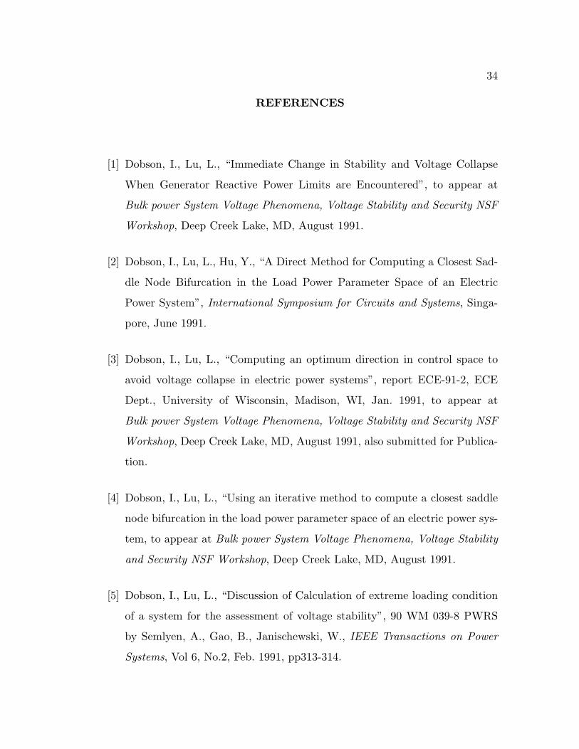
REFERENCES
[1] Dobson, I., Lu, L., “Immediate Change in Stability and Voltage Collapse
When Generator Reactive Power Limits are Encountered”, to appear at
Bulk power System Voltage Phenomena, Voltage Stability and Security NSF
Workshop, Deep Creek Lake, MD, August 1991.
[2] Dobson, I., Lu, L., Hu, Y., “A Direct Method for Computing a Closest Sad-
dle Node Bifurcation in the Load Power Parameter Space of an Electric
Power System”, International Symposium for Circuits and Systems, Singa-
pore, June 1991.
[3] Dobson, I., Lu, L., “Computing an optimum direction in control space to
avoid voltage collapse in electric power systems”, report ECE-91-2, ECE
Dept., University of Wisconsin, Madison, WI, Jan. 1991, to appear at
Bulk power System Voltage Phenomena, Voltage Stability and Security NSF
Workshop, Deep Creek Lake, MD, August 1991, also submitted for Publica-
tion.
[4] Dobson, I., Lu, L., “Using an iterative method to compute a closest saddle
node bifurcation in the load power parameter space of an electric power sys-
tem, to appear at Bulk power System Voltage Phenomena, Voltage Stability
and Security NSF Workshop, Deep Creek Lake, MD, August 1991.
[5] Dobson, I., Lu, L., “Discussion of Calculation of extreme loading condition
of a system for the assessment of voltage stability”, 90 WM 039-8 PWRS
by Semlyen, A., Gao, B., Janischewski, W., IEEE Transactions on Power
Systems, Vol 6, No.2, Feb. 1991, pp313-314.
Page 39
35
[6] Proceedings: Bulk power system voltage phenomena-voltage stability and
security, EPRI Report EL-6183, Potosi, Missouri, Jan. 1989.
[7] C. Barbier, J-P. Barret, “Analyse des phenomenes d’ecroulement de tension
sur un reseau de transport” (An analysis of phenomena of voltage collapse
on a transmission system), Revue Generale de L’Electricite, Tome 89, No.
10 Octobre 1980, pp. 672–690.
[8] W.R. Lachs, “System reactive power limitations”, IEEE 1979 Power Engi-
neering Society Winter Meeting, 79CH1417-5 PWR, A79 015-9.
[9] P. Borremans, A. Calvaer, J.P. De Reuck, J. Goosens, E. Van Geert, J.
Van Hecke, A. Van Ranst, “Stabilite de tension: Aspects fondamentaux et
comparaison de critere pratiques”, CIGRE Report 38-11, 1984.
[10] Th. Van Cutsem, “Network optimization–based reactive power margin cal-
culation”, Power Systems Modelling and Control Applications, ed. A. J. Cal-
vaer, IFAC Proceedings Series, No. 9, 1989, pp. 195–201.
[11] M.M. Begovic, A.G. Phadke, “Analysis of voltage collapse by simulation”,
International Symposium on Circuits and Systems, Portland, OR, May 1989.
[12] M.A. Pai, M.G. O’Grady, “Voltage collapse analysis with reactive genera-
tion and voltage dependent load constraints”, Electric Machines and Power
Systems, 17, 1989, pp 379–390.
[13] K.T. Vu, C.C. Liu, “Dynamic mechanisms of voltage collapse”, Systems and
Control Letters, vol. 15, 1990, pp. 329-338.
Page 40
36
[14] T. Van Cutsem, “A method to compute reactive power margins with respect
to voltage collapse”, IEEE Transactions on Power Systems, vol. 6, no. 1, Feb.
1991, pp. 145–156.
[15] I. Dobson, H.-D. Chiang, “Towards a Theory of Voltage Collapse in Electric
Power Systems,” Systems and Control Letters, Vol. 13, 1989, pp. 253-262.
[16] I. Dobson, H.-D. Chiang, J.S. Thorp, L. Fekih-Ahmed, “A Model of Voltage
Collapse in Electric Power Systems,” Proceedings of the 27th IEEE Control
and Decision Theory Conference, Austin, Texas, Dec. 1988, pp. 2104-2109.
[17] V. Ajarapu, B. Lee, “Bifurcation theory and its application to nonlinear
dynamical phenomena in an electrical power system”, Power Industry and
Computer Applications Conference, Baltimore, Maryland, May 1991.
[18] E.H. Abed, A.M.A. Hamdan, H-C. Lee, A.G. Parlos, “On bifurcations in
power system models and voltage collapse”, Proceedings of the 29th Confer-
ence on Decision and Control, Honolulu, Hawaii, Dec. 1990, pp. 3014-3015.
[19] B. M. Weedy, Electric Power Systems, J. Wiley & Sons, Great Britain, 1972
pp 55-60.
[20] A. Capasso, E. Mariani, “Inflence of generator capability curves representa-
tion on system voltage and reactive power control studies,” IEEE Transa-
tions on PAS , vol. PAS-97, no. 4 , July/Aug 1978, pp. 1036-1041.
[21] J. M. T. Thompson, H. B. Stewart, Nonlinear Dynamics and Chaos, John
Wiley and Sons, Great Britain, 1987.
[22] J. Guckenheimer, P. Holmes, Nonlinear oscillations, dynamical systems and
bifurcations of vector fields, Springer-Verlag, NY, 1986.
Page 41
37
[23] NAG Fortran Library Manual Mark 13, Volume 2, D02EBF, NP1490/13,
July, 1988.
[24] T.J. Overbye, C.L. DeMarco, “Voltage security enhancement using energy
based sensitivities,” 90 SM 478-8 PWRS, IEEE/PES Summer Meeting, Min-
neapolis, MN, July 1990.
[25] S. Abe, Y. Fukunaga, A. Isono, B. Kondo, Power System Voltage Stability,
IEEE Transations on PAS, vol. PAS-101, No. 10, Oct. 1982.


![52407115 Voltage Stability[1]](https://static.documents.pub/doc/80x56/577d225a1a28ab4e1e97265d/52407115-voltage-stability1.jpg)


