Page 1
IMO I3C TDKJV PANELS
/ KARARA - FLOTATION, REGRINDING, AND SMS
Engineering Internship Final Report
A report submitted to the School of Engineering and
Energy, Murdoch University in partial fulfilment of the
requirements for the degree of Bachelor of Engineering.
Author: Scott Whitmore
Student Number: 30642906
Academic Supervisor: Associate Professor Graeme Cole, Murdoch University
Industry Supervisor: Paul Jones, Engineering Manager, Motherwell Automation
Unit Code/Name: ENG450 - Engineering Internship
Project Title: IMO I3c TDKJV Panels / Karara - Flotation, Regrinding, and SMS
Document Title: Engineering Internship Final Report.docx
Status: Final Revision
Due Date: 19 December 2011
Date Submitted: 19 December 2011
S c h o o l o f E n g i n e e r i n g a n d E n e r g y
Page 2
2
IMO I3c TDKJV Panels / Karara -
Flotation, Regrinding, and SMS
ENG450 - Engineering Internship Scott Whitmore
S/N: 30642906 Date Submitted: 19/12/2011
1 ABSTRACT
During their final year of university, engineering students at Murdoch University are given the
opportunity to gain practical experience by undertaking an internship work placement with an
engineering firm relevant to their particular major selected for study. Exposure to the work
environment allows the student to gain first-hand knowledge in order to better prepare
themselves for life after graduation.
Two major projects were undertaken during the internship work placement with Perth based
engineering firm, Motherwell Automation. Both projects relate directly to the Industrial
Computer Systems major offered at Murdoch University, although some sections of each project
were also relevant to the Instrumentation and Control Systems Engineering major. The
engineering units studied at Murdoch gave an important basis of understanding which was a
vital requirement to be able to successfully undertake the internship projects.
Completed first was the Karara – Flotation, Regrind, and Scavenger Magnetic Separation (SMS)
Project, followed by the IMO i3C TDKJV project. Time management proved to be an important
factor while working on both projects, as several project deliverables had strict deadlines which
were required to be met.
Each project provided significant challenges to overcome in order to successfully complete the
project according to the design requirements. Important practical skills were gained, such as
time management, client liaising, business communication and networking, as well as the
product knowledge learnt from utilising new hardware components and software packages.
Page 3
3
IMO I3c TDKJV Panels / Karara -
Flotation, Regrinding, and SMS
ENG450 - Engineering Internship Scott Whitmore
S/N: 30642906 Date Submitted: 19/12/2011
2 ACKNOWLEDGEMENTS
2.1 Motherwell Automation
Throughout the internship work placement, various members of the Motherwell Engineering
team provided vital assistance to various aspects of each project, including supervision and
support in both design and execution of the projects. The Motherwell staff played a key role in
the ability to successfully complete each internship project and I would like to take this chance to
specially thank all of them for the opportunity they have presented to me and for all the
essential help and support provided throughout the work placement.
I would specifically like to thank my industry supervisor, Paul Jones, the Engineering Manager at
Motherwell, to whom I owe my deepest gratitude. Also, Sholeh Pirmorady the Senior Engineer
who provided ongoing support and organised weekly meetings to assist all the internship
students at Motherwell. I would like to extend this thanks to Eddie Terrell, Operations Manager,
for providing the opportunity to work at Motherwell and Rick Da Paz, Karara Project Engineer for
his valuable assistance during the internship.
2.2 Murdoch University
I would like to offer my appreciation to Murdoch University and the staff members of the School
of Engineering, including my academic supervisor, Associate Professor Graeme Cole, and
Professor Parisa A. Bahri, for the opportunity to undertake an external placement and the
invaluable experience that came with completing it. The staff at Murdoch have successfully
provided a level of education that provides students with an amazing head-start into the world
of engineering. If it were not for their perpetual patience and passion for teaching, I would not
be where I am today.
Page 4
4
IMO I3c TDKJV Panels / Karara -
Flotation, Regrinding, and SMS
ENG450 - Engineering Internship Scott Whitmore
S/N: 30642906 Date Submitted: 19/12/2011
3 DOCUMENT CONTENTS
3.1 Table of Contents
1 ABSTRACT 2
2 ACKNOWLEDGEMENTS 3
2.1 MOTHERWELL AUTOMATION 3
2.2 MURDOCH UNIVERSITY 3
3 DOCUMENT CONTENTS 4
3.1 TABLE OF CONTENTS 4
3.2 LIST OF FIGURES 6
3.3 LIST OF TABLES 7
3.4 VERSION CONTROL 7
3.5 REFERENCED DOCUMENTS 7
3.6 DISCLAIMER 8
3.7 INDUSTRY AND ACADEMIC SUPERVISOR ENDORSEMENT PRO FORMA 8
3.8 GLOSSARY OF TERMS AND ABBREVIATIONS 9
4 INTRODUCTION 10
4.1 DOCUMENT INTRODUCTION 10
4.2 BACKGROUND ON MOTHERWELL AUTOMATION 11
5 INTERNSHIP WORK PLACEMENT SUMMARY 12
5.1 INTERNSHIP OBJECTIVES 12
5.2 TIME MANAGEMENT 12
6 IMO I3C TDKJV PANELS 13
6.1 PROJECT INTRODUCTION 13
6.2 DESIGN REQUIREMENTS 14
6.3 TECHNICAL REVIEW 19
6.4 DESIGN APPROACH AND DEVELOPMENT 22
6.5 DESIGN TESTING 25
6.6 FINAL PROJECT IMPLEMENTATION 27
6.7 PROJECT EVALUATION 32
7 KARARA - FLOTATION, REGRINDING AND SMS 33
Page 5
5
IMO I3c TDKJV Panels / Karara -
Flotation, Regrinding, and SMS
ENG450 - Engineering Internship Scott Whitmore
S/N: 30642906 Date Submitted: 19/12/2011
7.1 PROJECT INTRODUCTION 33
7.2 DESIGN REQUIREMENTS 38
7.3 TECHNICAL REVIEW 40
7.4 DESIGN APPROACH AND DEVELOPMENT 41
7.5 DESIGN TESTING 43
7.6 FINAL PROJECT IMPLEMENTATION 45
7.7 PID STANDARD TEMPLATE 48
7.8 PROJECT EVALUATION 56
8 INTERNSHIP EVALUATION 57
8.1 DEMONSTRATION OF THE WORK EXPERIENCE 57
9 BIBLIOGRAPHY 58
10 APPENDIX 59
10.1 APPENDIX A - TDKJV - IP ADDRESS SCHEDULE EXAMPLE 59
10.2 APPENDIX B - TDKJV - I/O MEMORY MAP EXAMPLE 60
10.3 APPENDIX C - AREA 1311 PROCESS FLOW DIAGRAM 61
10.4 APPENDIX D - KARARA PLC LOGIC STRUCTURE 62
Page 6
6
IMO I3c TDKJV Panels / Karara -
Flotation, Regrinding, and SMS
ENG450 - Engineering Internship Scott Whitmore
S/N: 30642906 Date Submitted: 19/12/2011
3.2 List of Figures
Figure 6.2.1 - Digital I/O Function Map 15
Figure 6.2.2 - TDKJV Panel Network Configuration 16
Figure 6.3.1 - IMO i3C Controller 19
Figure 6.3.2 - Moxa ioLogik E1200 20
Figure 6.3.3 - MOXA EDS-405A/408 Managed Ethernet Switch 21
Figure 6.4.1 - TDKJV - Design Prototype Layout 23
Figure 6.6.1 - Example of the final hardware configuration in a panel 27
Figure 6.6.2 - IMO i3C mounted on the BPS electrical panel 28
Figure 6.6.3 - Modbus over TCP Slave Scan List Example 29
Figure 6.6.4 - IMO i3C Control Logic Example 29
Figure 6.6.5 - Function Status Screen 30
Figure 6.6.6 - Overall Network Status Indication and Button 30
Figure 6.6.7 - Network Status Screen 31
Figure 7.1.1 - Karara Iron Ore Process Flow Diagram 34
Figure 7.3.1 - GE RX3i PLC 40
Figure 7.6.1 - Example of configuration logic for the flotation feed slurry density 45
Figure 7.6.2 - Example of control logic for the flotation feed slurry density 45
Figure 7.6.3 - Example of one step from the area start sequence 46
Figure 7.6.4 - Example of communications logic for a Profibus level transmitter 47
Figure 7.6.5 - Example of simulation logic for a solenoid water valve 47
Figure 7.7.1 - PID Function Overview 50
Figure 7.7.2 - Example of the PID object faceplates with different modes 52
Figure 7.7.3 - Example of a PID control faceplate in manual mode 53
Figure 7.7.4 - Example of a PID control faceplate in automatic mode 53
Figure 7.7.5 - Example of a PID control faceplate in cascade mode 53
Figure 7.7.6 - Example of the Engineering Setpoints faceplate 54
Figure 10.3.1 - Area 1311 Process Flow Diagram 61
Figure 10.4.1 - Karara PLC Logic Structure 62
Page 7
7
IMO I3c TDKJV Panels / Karara -
Flotation, Regrinding, and SMS
ENG450 - Engineering Internship Scott Whitmore
S/N: 30642906 Date Submitted: 19/12/2011
3.3 List of Tables
Table 3.8.1 - Glossary of Terms and Abbreviations 9
Table 6.2.1 - Digital I/O Requirments 17
Table 7.7.1 - Automatic Mode PID Tuning Parameters – Operator Setpoints 54
Table 7.7.2 - Default PID Parameters 55
Table 10.1.1 - TDKJV - IP Address Schedule Example 59
Table 10.2.1 - TDKJV - I/O Memory Map Example 60
3.4 Version Control
VERSION DATE OF SUBMISSION SUBMISSION DESCRIPTION
1.0 18/11/2011 Submitted for initial review
2.0 19/12/2011 Submitted for final review
3.5 Referenced Documents
REF. DOCUMENT TITLE REVISION
1. Engineering Internship Project Plan 1
2. Engineering Internship Progress Report 1
3. PACSystems CPU Reference Manual (GFK-2222) Q
Page 8
8
IMO I3c TDKJV Panels / Karara -
Flotation, Regrinding, and SMS
ENG450 - Engineering Internship Scott Whitmore
S/N: 30642906 Date Submitted: 19/12/2011
3.6 Disclaimer
All of the work discussed in this report is the work of the author unless otherwise referenced.
I declare the following to be my own work, unless otherwise referenced, as defined by Murdoch
University’s policy on plagiarism.
Signed: Scott Whitmore
Date:
3.7 Industry and Academic Supervisor Endorsement Pro Forma
This is to be signed by both the industry and academic supervisor and attached to the final
report submitted for the internship.
We are satisfied with the progress of this internship project and that the attached report is an
accurate reflection of the work undertaken.
Signed: Industry Supervisor
Date:
Signed: Academic Supervisor
Date:
Page 9
9
IMO I3c TDKJV Panels / Karara -
Flotation, Regrinding, and SMS
ENG450 - Engineering Internship Scott Whitmore
S/N: 30642906 Date Submitted: 19/12/2011
3.8 Glossary of Terms and Abbreviations
ITEM DESCRIPTION
BOOL Boolean
BPS Bridging Power Station
BWWTP Bridging Waste Water Treatment Plant
CAD Computer Aided Design
CMS Cleaner Magnetic Separation
CRO Control Room Operator
CV Control Variable
CVLS Construction Village Lift Station
DOL Direct On-Line
EGD Ethernet Global Data
ENG Engineering
FAT Factory Acceptance Test
GE General Electric
HMI Human Machine Interface
IEC International Electro-technical Commission
HPGR High Pressure Grinding Rolls
HV High Voltage
I/O Input/output
ICSE Industrial Computer Systems Engineering
IMS Intermediate Magnetic Separation
IP Internet Protocol
ISA International Society of Automation
MCB Main Communications Building
P&ID Piping and Instrumentation Diagram
PCS Process Control System
PID Proportional Integral Derivative
PLC Programmable Logic Controller
PME Proficy Machine Edition
PV Process Variable
RIO Remote Input/output
RMS Rougher Magnetic Separation
RTU Remote Terminal Unit
SCADA Supervisory Control And Data Acquisition
Silica Silicon Dioxide
SMS Scavenger Magnetic Separation
SP Setpoint
TDKJV Thiess Decmil Kentz Joint Venture
UDT User-Defined Data Type
VSD Variable Speed Drive
Table 3.8.1 - Glossary of Terms and Abbreviations
Page 10
10
IMO I3c TDKJV Panels / Karara -
Flotation, Regrinding, and SMS
ENG450 - Engineering Internship Scott Whitmore
S/N: 30642906 Date Submitted: 19/12/2011
4 INTRODUCTION
4.1 Document Introduction
Murdoch University’s Engineering Internship Program provides students with the opportunity to
work alongside highly skilled, experienced engineers, while gaining valuable practical knowledge.
The Engineering Internship Final Report provides an extensive overview of the two major
projects completed during the internship work placement with engineering firm, Motherwell
Automation.
The Engineering Internship Project Plan (Ref.1) originally intended one project to be completed,
the IMO i3C TDKJV Panels. Whilst in completion, another project with Motherwell was tasked,
involving the PLC programming and testing for the flotation, regrinding, and SMS area of the
Karara Iron Ore Mine plant control system (PCS), commissioned to Motherwell Automation at
the start of 2011. Similar time was spent on both projects, and therefore the extent of detail will
be covered equally in this document.
Enclosed in this report are descriptions of the major design stages for each project, including a
project introduction, the design requirements, technical review, design approach and
development, testing, final implementation, and project evaluation. Throughout each section are
discussions on the relevant design decisions made and the reasoning behind them. Details about
the significant experiences gained while working on each project are also covered.
This document is intended to be read by someone with a technical background in industrial
computer systems in order to gain a complete understanding of its content.
Page 11
11
IMO I3c TDKJV Panels / Karara -
Flotation, Regrinding, and SMS
ENG450 - Engineering Internship Scott Whitmore
S/N: 30642906 Date Submitted: 19/12/2011
4.2 Background on Motherwell Automation
Motherwell Automation is a Perth based engineering consultancy firm which has provided
engineering solutions and life cycle support services to the Australian market for over eighteen
years. They provide their clients with a broad range of project management solutions, including
feasibility and optimisation studies, concept design and development through to full
commissioning, and onsite support.
The engineering team at Motherwell comprises of highly skilled, multi-disciplined staff with a
diverse range of backgrounds and expertise including:
PLC Systems
Electronics
Mechatronics
SCADA
Process and Control
Motherwell has a wealth of experience across a broad range of industries and applications
including:
Mining & Resources
Mineral Processing
Oil & Gas
Power and Utilities
Water & Waste Water
Materials & Bulk Handling
Power and Utilities
Communications
Marine
Food and Beverage
(Motherwell Automation, 2011)
Page 12
12
IMO I3c TDKJV Panels / Karara -
Flotation, Regrinding, and SMS
ENG450 - Engineering Internship Scott Whitmore
S/N: 30642906 Date Submitted: 19/12/2011
5 INTERNSHIP WORK PLACEMENT SUMMARY
5.1 Internship Objectives
The aim of the university internship work experience program is to provide students with
exposure to the applied world of engineering design and implementation through a period of
workplace employment in the area of industrial computer systems engineering. Several
outcomes achieved through the work placement at Motherwell Automation involve the
following:
Work experience gained under the direction of a person experienced in the workplace.
Practical experience achieved in the application of an engineering approach to problem
solving in the workplace.
Production of results from the work experience through both verbal and written
presentations.
5.2 Time Management
Due to the fact that the Karara Project was not included in the original Engineering Internship
Project Plan (Ref.1), no formal task schedule for this project was completed. Instead, a schedule
was provided by Motherwell Automation, which formed project deadlines around the start of
the Factory Acceptance Test (FAT) procedure for the flotation, regrinding, and SMS area of the
Karara PCS project. The completion of the Karara Iron Ore project was given a higher priority
than that of the TDKJV Panels by Motherwell management, and therefore the project was
completed before work continued on the original TDKJV Panel project. A task schedule
comparison can be found in the Engineering Internship Progress Report (Ref.2)
Page 13
13
IMO I3c TDKJV Panels / Karara -
Flotation, Regrinding, and SMS
ENG450 - Engineering Internship Scott Whitmore
S/N: 30642906 Date Submitted: 19/12/2011
6 IMO I3C TDKJV PANELS
6.1 Project Introduction
6.1.1 Barrow Island Project Background
The Greater Gorgon Development Project operated by Chevron Australia Pty
Ltd. is based upon the installation of a sub-sea gathering system that taps into
an estimated gas resource in excess of 40 trillion cubic feet. A 70 kilometre sub-
sea pipeline connects the gas fields to a gas processing facility stationed on the central-east
Coast of Barrow Island, located off the North West coast of Western Australia.
TDKJV is a joint venture between Thiess Pty Ltd, Decmil Australia and Kentz Pty Ltd who have
been awarded the contract to design and build a construction village on Barrow Island. This aims
to provide accommodation and services infrastructure for 3300 persons to support the
construction of the gas processing facility.
6.1.2 Project Scope
A realisation was discovered during the work placement with Motherwell, that a project’s scope
is commonly dynamic in nature. The following project scope, including design requirements,
describes the final version of these details, with some discussion on the occurring changes.
Motherwell Automation is contracted by TDKJV to provide equipment supply, and panel
assembly, for the purpose of inter-tripping, load-shedding, and differential protection, of the
electrical power distributed to several areas of the construction village on Barrow Island. All
engineering services required to supply these panels are also provided by Motherwell. The IMO
i3C TDKJV Panel internship project consists of the engineering services for the design,
implementation, and testing of a control solution to be used in the panels provided to TDKJV by
Motherwell Automation. The control solution must comply with all project design requirements.
6.1.3 Assumptions
Engineering services, including hardware procurement, construction, and commissioning of the
actual electrical panels supplied to TDKJV is not incorporated in this project. Only engineering
services pertaining to the development and implementation of the control solution required for
the panels operation are included. A large portion of this project also focuses on
communications between the controller and the remote I/O (RIO) used in each panel. In
addition, significant time was also spent exploring the functionality of the IMO i3C controller.
Page 14
14
IMO I3c TDKJV Panels / Karara -
Flotation, Regrinding, and SMS
ENG450 - Engineering Internship Scott Whitmore
S/N: 30642906 Date Submitted: 19/12/2011
6.2 Design Requirements
The design requirements of the TDKJV panel project, as decided by the client, were to increase
functionality and improve control of the electrical power distributed to the construction villages
on Barrow Island. No formal design description or functional description specification was
submitted by the client, making it difficult to follow any official guidelines or standards, however
this did allow for the freedom to design the control solution as desired.
The following design requirements were based upon verbal discussions with the projects lead
engineer from TDKJV and continually revised throughout the term of the project. This contact
with the client provided an excellent opportunity to gain first-hand experience with client
liaising, whilst also improving business communication and networking skills.
6.2.1 Control Solution Requirements
The final control solution design was required to provide the following five major functions,
utilising the IMO i3C controller. The final design followed these requirements as a measurement
of success for the TDKJV project.
6.2.1.1 Differential Protection Tripping
The i3C controller is required to monitor the under voltage and under frequency digital inputs
from two differential protection relays located in the Bridging Power Station (BPS) Panel and
energise a trip relay in the Main Communications Building (MCB) Panel when either of the BPS
inputs are energised.
6.2.1.2 Load Shedding
Electrical power for the construction village is generated on Island. Load shedding a.k.a. ‘rolling
blackouts’ of non-essential loads are used to protect the power supply when electrical demand is
high. Digital inputs in the MCB panel are required to be monitored by the controller, each one
corresponding to a group of construction village clusters in a specific order. Depending on power
requirements, the operator may choose how many clusters require load shedding. The cluster
load shedding order is as follows:
1 Clusters 1 and 2
2 Clusters 3 and 4
3 Clusters 5 and 6
4 Clusters 7, 8, and 9
5 Clusters 10, 11 and 12
Page 15
15
IMO I3c TDKJV Panels / Karara -
Flotation, Regrinding, and SMS
ENG450 - Engineering Internship Scott Whitmore
S/N: 30642906 Date Submitted: 19/12/2011
6.2.1.3 Potable Water Pump Disable Function
The IMO i3C controller is required to energise a digital output if a Potable Water High Level
Switch contact in either CVLS panel becomes energised. This output will de-energise a trip relay
in the BPS panel to disable the Potable Water Pump through field wiring.
6.2.1.4 Inter-tripping
A digital input in the Bridging Waste Water Treatment Plant (BWWTP) Panel is monitored from
the controller. The controller energises a trip relay in the Construction Village Lift Station (CVLS)
Panel when the BWWTP input is energised.
6.2.1.5 Live Status Monitoring
The status of each function is also required to be displayed on a HMI screen for the purpose of
monitoring the live status of each function. It is necessary that the interface be simple to use
with minimal training of how to operate the IMO i3C controller.
6.2.2 Function Map
The following Figure 6.2.1 - Digital I/O Function Map, displays the relationship of the digital I/O
between each panel area and the corresponding function required in the final control solution.
Figure 6.2.1 - Digital I/O Function Map
Page 16
16
IMO I3c TDKJV Panels / Karara -
Flotation, Regrinding, and SMS
ENG450 - Engineering Internship Scott Whitmore
S/N: 30642906 Date Submitted: 19/12/2011
6.2.3 Core Network Configuration
Utilising the existing fiber optic network, new MOXA Ethernet switches are required to provide
gigabit fiber optic connectivity for the communications network, an essential element to
successfully implement the control solution. The network supplies connectivity to the load
shedding and inter tripping I/O in the BWWTP, BPS Substation, MCB, CVLS 1 & 2, and 12 Clusters.
The network edge in each of these locations is comprised of MOXA EDS-405A and EDS-408
switches which deliver connectively to devices on the network, as well as the media conversion
from Fiber Optic to Ethernet. This network provides a medium for MOXA E1212-T remote I/O
devices which utilise Modbus over TCP for communications, the details of which are in section
6.3.5 Modbus over TCP in this document.
Figure 6.2.2 - TDKJV Panel Network Configuration
Page 17
17
IMO I3c TDKJV Panels / Karara -
Flotation, Regrinding, and SMS
ENG450 - Engineering Internship Scott Whitmore
S/N: 30642906 Date Submitted: 19/12/2011
6.2.4 Controller Variables
Process variables required to be controlled by the i3C device were specified by the client to be
utilised in each function. The following information provides details on these specific variables.
6.2.4.1 Digital I/O List
PANEL LOCATION DESCRIPTION DIGITAL I/O TYPE NUMBER OF I/O
BPS Differential protection normally open contacts Input 4
Potable water disabling trip relay Output 1
MCB Load Shedding normally open contacts Input 5
Differential protection trip relay Output 1
BWWTP BWWTP Trip normally open contact Input 1
CVLS 1
Lifter high level alarm for potable water disabling - Normally open contact
Input 1
CVLS inter-tripping trip relay Output 1
CVLS 2
Lifter high level alarm for potable water disabling - Normally open contact
Input 1
CVLS inter-tripping trip relay Output 1
Clusters 1-12 Load Shedding trip relay Output 1 (each)
Table 6.2.1 - Digital I/O Requirments
6.2.4.2 IP Address Schedule
Class B private IP addresses in the range 192.168.0.xxx (subnet mask of 255.255.0.0) have been
assigned by TDKJV for use on the network. The unique IP addresses were given to each I/O block,
network switch, and the IMO i3C Controller. An example of the TDKJV IP Address Schedule can be
found in section 10.1 Appendix A - TDKJV - IP Address Schedule Example.
6.2.5 Hardware Requirements
When the equipment for the project was originally procured, the controllers selected for the
design solution were two MOXA E2242 RTU Controllers. While starting the technical review of
the E2242, it was quickly discovered that it would not meet the design requirements of the
project. The MOXA E2242 RTU is designed predominantly as an interface to field devices and not
as a primary controller. After deliberation with Motherwell senior engineers and sales staff, a
replacement was found which met all the design requirements for the project, as well as costing
less than the original two controllers.
The IMO i3C was selected as the replacement for the control solution, and became the focus for
the entire project. While completely meeting all design requirements for the project, the i3C also
Page 18
18
IMO I3c TDKJV Panels / Karara -
Flotation, Regrinding, and SMS
ENG450 - Engineering Internship Scott Whitmore
S/N: 30642906 Date Submitted: 19/12/2011
added the new functionality of providing a HMI screen for operators to monitor the live status of
each function. This functionality then became a new design requirement after consultations with
the client.
Several pieces of equipment have been selected by Motherwell for use on the project and are
therefore exclusively used.
Controller: IMO i3C Controller
Controller Software: IMO i3C Configurator
Remote I/O: MOXA ioLogik
Ethernet Switches: MOXA Switches
6.2.6 Hardware Installation Overview
The project’s design requirements involve electrical panels installed in various buildings and
locations across the Accommodation Village as illustrated in Figure 6.2.2 - TDKJV Panel Network
Configuration. The only significant variation of the common hardware is the BPS panel, which is
required to house the IMO i3C controller.
Common to each panel is the following hardware:
24VDC Power Supply
MOXA ioLogik E1212-T Remote I/O
MOXA Switch EDS-405A / 408
Copper wiring
Terminal Blocks
All hardware procurement and assembly was provided by skilled Motherwell engineers. While
hardware construction was outside the scope of this project, understanding the installation
requirements was an important step in learning how to correctly interface with each field device
for the final control solution.
Page 19
19
IMO I3c TDKJV Panels / Karara -
Flotation, Regrinding, and SMS
ENG450 - Engineering Internship Scott Whitmore
S/N: 30642906 Date Submitted: 19/12/2011
6.3 Technical Review
To gain the essential knowledge vital for use in the design and implementation of the IMO i3C
control solution, several pieces of hardware and software required technical research before any
development of the project proceeded. Knowledge gained in the Industrial Computer Systems
Engineering (ICSE) Units at Murdoch University, primarily ENG305 ‘PLC Systems’ and ENG345
‘SCADA and Instrument Systems’, gave an excellent basis of understanding how these devices
should operate. This technical review will also include a description on how each of these
technologies was incorporated into the project.
6.3.1 IMO i3C Controller
IMO's i3C controller is an ‘all-in-one’ type control unit since
it combines automated control, user interface, I/O and
networking into a single device. It is also, small, powerful
and has many connectivity features including Modbus over
TCP. The following are the beneficial features of the IMO
i3C. (IMO Precision Controls Ltd, 2009)
A bright 10” graphical touch LCD display with 10
programmable function keys
Display of complex graphical objects including trends, gauges, meters and animations
Advanced control capabilities including floating point, multiple auto-tuning PID loops and
string handling capabilities
Removable media for up to two gigabytes of storage of programs, data logging etc.
iCAN networking port for communication with remote I/O, other controllers or PCs
USB networking port for communication with PCs and programming of controller
Configurable serial protocols for communication to drives, PLCs, or other serial peripherals
Full featured, built-in I/O including high resolution analogue, thermocouple, RTD, high speed
counters, PWM outputs and relays (depending upon the i3 model used)
Optional communication add-on modules that allow additional capabilities such as Ethernet
or modems
The i3C is the backbone of this project. By connecting each panel using Modbus over TCP to the
unit, it provides complete control over the functional requirements for the project. The touch
screen interface allows this operator easy access to the necessary live statuses for each function
and a network status screen to monitor connectivity.
Figure 6.3.1 - IMO i3C Controller
Page 20
20
IMO I3c TDKJV Panels / Karara -
Flotation, Regrinding, and SMS
ENG450 - Engineering Internship Scott Whitmore
S/N: 30642906 Date Submitted: 19/12/2011
6.3.2 IMO i3C Configurator
The IMO i3C Configurator programming software, allows both the controller logic and HMI
display to be programmed and configured from one integrated application. The control logic is
programmed using standard ‘ladder logic’ and the HMI display is programmed through a
graphical interface. (IMO Precision Controls Ltd, 2009)
This software is the primary programming toolkit used in this project. It contains all the control
logic, HMI screens, and Modbus over TCP network configurations.
6.3.3 MOXA ioLogik E1200
MOXA's ioLogik E1200 is a digital remote I/O (RIO) device
which communicates to a controller over Ethernet using the
Modbus over TCP protocol. It comes with two embedded
Ethernet switch ports that can be used to form a daisy-chain
topology for easy cabling.
In the TDKJV project, several panels require access to I/O
located at remote sites where space is limited. The daisy-
chain capability allows ioLogik E1200 units to connect to one
other in series or to other nearby Ethernet devices, saving on
both space and wiring costs.
“To control an input or output channel of a remote Ethernet I/O device, running the most general
Modbus/TCP protocol requires specifying the Modbus address of those input and output
channels. The ioLogik E1200 offers the greatest flexibility with its user-defined Modbus/TCP
addressing. With this approach, the ioLogik E1200's addressing is compatible with all other
Modbus/TCP devices, and the channels that are being used can be managed sequentially and
require less polling.” (Moxa, 2009)
6.3.4 MOXA EDS-405A/408 Managed Ethernet Switch
The MOXA EDS-405A/408A are specifically industrial designed Managed Ethernet switches, built
with a variety of functions and applications designed to suit industrial requirements, including
support for EtherNet/IP and Modbus/TCP protocols. These switches are built with 3, 6 and 8
Ethernet ports, depending on design requirements. The switches provide gigabit fiber optic
media conversion and connectivity through 100BaseFX ports with SC/ST connectors.
Figure 6.3.2 - Moxa ioLogik E1200
Page 21
21
IMO I3c TDKJV Panels / Karara -
Flotation, Regrinding, and SMS
ENG450 - Engineering Internship Scott Whitmore
S/N: 30642906 Date Submitted: 19/12/2011
The TDKJV communications network utilises the MOXA
EDS-405A/408A together with the existing fiber optic
network already installed on the Island, to provide a
communications medium for MOXA E1212-T remote
I/O devices, which employs Modbus over TCP to
read/write to the IMO i3C controller. To minimise
costs, MOXA IMC-101 Series Media Converters were
used in both CVLS 1 and 2. These devices perform the
same fiber optic to Ethernet media conversion, as the
EDS-405A/408, but without the managed Ethernet
switch functionality.
6.3.5 Modbus over TCP
Standard Modbus is a serial communications protocol designed for use with programmable logic
controllers (PLCs). Modbus over TCP utilises the same protocol, but via a different method of
communication. Rather than communicating over a serial medium, it communicates via
Ethernet. Ethernet is still a type of serial communication, but has significant advantages over
RS422 and RS232 including the ability for two or more devices connected via Ethernet to
communicate over a large network.
The Modbus protocol is straightforward and robust; it has since become a common standard
communications method in the industrial communications industry, and it is now amongst the
most commonly available means of connecting industrial electronic devices. Modbus over TCP
allows for communication between many (approx. 240) devices to be connected on the same
Ethernet network.
Modbus devices can be configured in two operating modes, ‘Master’ and ‘Slave’. Each device is
given a unique Modbus address. The Master sends a Modbus function command containing the
address of the intended Slave and the corresponding Modbus register which contains the
location of the required data to be read or written. All devices will receive the command, but
only the intended slave will respond. Different control requirements correspond to different
function codes. For example, in order to read a discrete input, the Modbus Master would send
the function code 2 to the intended slave and include the Modbus register for the relevant
discrete input.
The Modbus over TCP protocol is the primary method of communication between the IMO i3C
controller and the MOXA ioLogik E1200 units.
Figure 6.3.3 - MOXA EDS-405A/408 Managed
Ethernet Switch
Page 22
22
IMO I3c TDKJV Panels / Karara -
Flotation, Regrinding, and SMS
ENG450 - Engineering Internship Scott Whitmore
S/N: 30642906 Date Submitted: 19/12/2011
6.4 Design Approach and Development
This section explains the design approach and reasoning for significant decisions made
throughout the development stage of the project.
6.4.1 Development Procedure
The design methodology used in the development of the control solution involved significant
stages that separated each design phase. After completing the technical review of the software
and hardware requirements for the project, the development of the design followed these major
steps:
1 Construction of the hardware Prototype
2 Control logic development
3 HMI development
4 Modbus protocol configuration
5 Design testing on prototype hardware
6 Problem resolution
7 Design testing on final hardware
8 Final problem resolution
9 Submission of deliverables
Significant time during the project was also spent creating Computer Aided Design (CAD)
drawings for the hardware installation. These drawings included general arrangements and
schematics for each panel. While the drawings only had a small effect on the control solution
design, they did assist in gaining a complete understanding of the panel installation and physical
interaction of the digital I/O, as well as providing a new skill and experience in creating CAD
drawings.
Page 23
23
IMO I3c TDKJV Panels / Karara -
Flotation, Regrinding, and SMS
ENG450 - Engineering Internship Scott Whitmore
S/N: 30642906 Date Submitted: 19/12/2011
6.4.1.1 Design Prototype
The control solution design was started by first building a testing prototype rig with the following
hardware:
An IMO i3C Controller
A MOXA ioLogik E1200
D-Link 4-Port Ethernet switch
24V power supply
A digital input simulator
A trip relay
A laptop with the IMO i3C Configurator Software
The purpose of first using a smaller setup, rather than designing the control solution on the final
configuration, was to find potential hardware incompatibilities before the panels were
constructed as well as providing a configuration that was easier to manage while developing the
software logic. It also meant that development on the project could start before the construction
of the panels commenced and proved an essential step in the development of the control
solution.
Figure 6.4.1 - TDKJV - Design Prototype Layout
6.4.1.2 Controller Design Approach
Since the controller logic design is relatively straightforward, the knowledge learnt in the
Industrial Computer Systems Unit, ENG305 ‘PLC Systems’, combined with the technical research
of the IMO i3C Configurator, meant programming the controller in standard ladder logic was able
to be completed in under a day. However, the communications mapping using Modbus over TCP
proved to be more of a challenge and required a few extra days to complete and test correctly.
Page 24
24
IMO I3c TDKJV Panels / Karara -
Flotation, Regrinding, and SMS
ENG450 - Engineering Internship Scott Whitmore
S/N: 30642906 Date Submitted: 19/12/2011
6.4.1.3 HMI Design Approach
The HMI design was required to display live status monitoring of each function of the control
solution. Another requirement of the HMI design was to allow operation of the controller with
minimal training of the IMO i3C. The design methodology used was to keep the interface as
simple as possible while still providing all the necessary information to the operator. It was
decided that the status indication of each function was to be overlaid on top of a graphical
representation of each controller function, linking the relevant digital inputs to the
corresponding outputs.
Designs were first sketched on paper and continually edited until a final design was found, which
was both simple and efficient. These designs were then implemented using the IMO i3C
Configurator. The only major issue when applying the design sketches was the restriction of ‘real
estate’ on the screen (the amount of usable space available to add content). This meant that the
designs overall efficiency needed improving in order to correctly implement each function, while
still complying with all design requirements. Eventually a compromise was met for the final HMI
screen design, which can be found in section 6.6.4 Final HMI Screens.
Inside the software of the i3C, each digital I/O status has its own unique memory address. The i3C
Configurator allows these addresses to be directly displayed as indicators on the HMI screen.
Interaction to the screen can be programmed using buttons to either write to a memory address,
or to perform a standard function, such as switching to a different screen. It was these tools
which were primarily used to implement the design.
6.4.1.4 Modbus over TCP Configuration Approach
While programming the Modbus software configurations, it quickly became apparent that the
IMO i3C help files and support documentation lacked the more advanced detail required to
correctly configure the Modbus Protocol. This includes important information such as the details
of the Modbus device status registers which were manually configured to determine the live
status of the communications between the controller and the I/O blocks.
During the technical review of the IMO i3C Configurator, it was found that the software used by
IMO was a rebranded version of Cscape, developed by Horner APG. Fortunately this meant that
there was another source of support documentation which was able to be utilised to provide
enough detail to correctly configure the Modbus protocol. (Horner APG, 2009)
By using the new support documentation, the network configuration was quickly programmed
into the IMO i3C for each slave device. Once programmed, each configuration was tested utilising
the design prototype.
Page 25
25
IMO I3c TDKJV Panels / Karara -
Flotation, Regrinding, and SMS
ENG450 - Engineering Internship Scott Whitmore
S/N: 30642906 Date Submitted: 19/12/2011
6.5 Design Testing
6.5.1 Internal Testing
Internal testing was first completed on the smaller prototype rig, the purpose of which was to
reduce complications which could arise from hardware incompatibilities. Since only one RIO unit
was used in this setup, the IP address was changed repeatedly to match each slave device. All
digital I/O was tested for each slave device by switching the on/off position of the digital input
simulator, and monitoring the output status of the trip relay and corresponding HMI indicators.
After confirmation of the trip functionality was completed, the software was downloaded to the
final configuration built by Motherwell engineers.
Once the final configuration was complete and the software was downloaded, an inclusive test
of the hardware and software was performed.
6.5.2 Design Problems
6.5.2.1 Communications Loss/Reacquire
During the internal testing the most serious problem that occurred was the reacquisition of the
network between the i3C and the ioLogik RIO devices after a communications loss had occurred
and been repaired.
There are a number of possible reasons that could be attributed to a communications loss in an
offending panel, such as:
Loss of power (intentional or not)
Failure or removal of CAT6 or fiber patch leads
Failure of media convertor module
Failure of Ethernet switch
Failure of remote I/O device
The i3 configurator help manual confirms that the i3 controller should automatically attempt to
reacquire a connection to remote devices after a communications failure, with a user
configurable reacquire time programmed. After deliberation with an IMO representative, this
functionality still failed to provide a 100% success rate for reacquisition. Since any failure of
communications is unacceptable, and in some cases dangerous, a work around had to be
implemented, the details of which can be found in section 6.6.3 Final Controller Logic.
Page 26
26
IMO I3c TDKJV Panels / Karara -
Flotation, Regrinding, and SMS
ENG450 - Engineering Internship Scott Whitmore
S/N: 30642906 Date Submitted: 19/12/2011
6.5.3 Factory Acceptance Test
The Factory Acceptance Test (FAT) was a formal test with a client representative present. This
was conducted at the Motherwell Automation premises, using appropriate field equipment and
simulated field equipment where appropriate. A test procedure document was submitted to the
client for review prior to the FAT. This document was then used as a test schedule involving the
following items:
Overall Presentation and Inspection
MCB Load Shedding Functions
Construction Village BPS Under Frequency/Under Voltage Function
BWWTP Trip Function
LPG Panel Function
Network Operation Review
BPS Panel Inspection
Any test failures or modifications were recorded and rectified after the FAT and immediately re-
tested prior to the panels being shipped to site. Fortunately, the only changes required for the
control solution were minor cosmetic alterations to the touch screen display.
Page 27
27
IMO I3c TDKJV Panels / Karara -
Flotation, Regrinding, and SMS
ENG450 - Engineering Internship Scott Whitmore
S/N: 30642906 Date Submitted: 19/12/2011
6.6 Final Project Implementation
This section contains a detailed description of the implementation for the final control solution
submitted to the client upon completion of the project.
6.6.1 Final Hardware Configuration
The figure below Figure 6.6.1 - Example of the final hardware configuration in a panel shows
some of the common hardware used inside the electrical panels. All of the equipment in the
panels are DIN rail mounted for convenience. While the procurement and construction of the
actual electrical panels are not incorporated in this project, it is important to be aware of the
configuration of the hardware to understand its relationship to the control solution software.
The example contains the following hardware layout from left to right:
230VAC Circuit Breaker
24VDC Power Supply
Trip Relay
24VDC Circuit Breaker
Power Terminal Block
MOXA Fiber Optic to Ethernet Media Converter
MOXA ioLogik E1200-T RIO Unit
Figure 6.6.1 - Example of the final hardware configuration in a panel
Page 28
28
IMO I3c TDKJV Panels / Karara -
Flotation, Regrinding, and SMS
ENG450 - Engineering Internship Scott Whitmore
S/N: 30642906 Date Submitted: 19/12/2011
The second Figure 6.6.2 - IMO i3C mounted on the BPS electrical panel, illustrates the hardware
configuration of the IMO i3C controller on the outside of the BPS electrical panel door. On the
left side, inside the door, a similar configuration to the previous figure is shown, although this
also displays the fiber optic leads connected to the MOXA EDS-405A switch.
Figure 6.6.2 - IMO i3C mounted on the BPS electrical panel
6.6.2 Final Network Configuration
Communication between the IMO i3C controller and the MOXA E1212-T remote I/O are
configured to use Modbus over TCP via the existing fiber optic network. A technical review of the
Modbus over TCP protocol can be found in section 6.3.5 Modbus over TCP. The Modbus protocol
was used exclusively in this project as it gave a simple and reliable method of communication
between the IMO i3C controller and the MOXA IoLogik RIO devices.
The IMO i3C controller is configured as the Modbus master and all MOXA E1212-T’s as the
Modbus slaves. Each device is configured with a unique IP address. An example of this can be
found in section 10.1 Appendix A - TDKJV - IP Address Schedule Example.
It is important to note that each E1212-T device has a default Modbus ID of 1, and must be
assigned this ID in the i3C protocol configuration to communicate correctly. Since each device has
a unique IP address, using the same slave ID will not conflict with one another.
The controller routinely polls the Modbus device registers in each slave device every 50ms, and
reads and/or writes the status of each digital I/O depending on the assigned polling type. The
Modbus Master (IMO i3C) maps this status in local memory which is used in the controller logic.
An example of the I/O memory map can be found in section 10.2 Appendix B - TDKJV - I/O
Memory Map Example. The digital status of each I/O stored in local memory, is also used to
display the live status of each function on the controllers HMI screen.
Page 29
29
IMO I3c TDKJV Panels / Karara -
Flotation, Regrinding, and SMS
ENG450 - Engineering Internship Scott Whitmore
S/N: 30642906 Date Submitted: 19/12/2011
Figure 6.6.3 - Modbus over TCP Slave Scan List Example illustrates the required configuration for
several of the slave devices used in the project. Once the IMO i3C Configurator software is
understood, and the slave device parameters are known, the tools used to configure these
devices are relatively simple to use.
Figure 6.6.3 - Modbus over TCP Slave Scan List Example
6.6.3 Final Controller Logic
A final version of the controller logic has been completed for each of the five major functions
listed in the project requirements, which can be found in section 6.2 Design Requirements. The
logic design consists of ‘ON/OFF’ control of digital outputs using conditions set by digital inputs,
and was reasonably simple to implement in ladder logic. An example of this logic is shown for the
inter-tripping function in Figure 6.6.4 - IMO i3C Control Logic Example. The BWWTP digital input
utilises a negated ladder contact, and when de-energised, sends power to both CVLS digital
outputs via a ladder coil.
Figure 6.6.4 - IMO i3C Control Logic Example
Specific logic was also implemented to solve the communications loss/reacquire problem. The
solution to the issue was applied by monitoring a Modbus slave device status register from the
controller for each RIO unit. The status register provides a timeout status when a slave device is
unresponsive and displays this status on the HMI touch screen. When the ‘reacquire’ input is
selected on the HMI screen, the control logic forces a manual reacquire attempt to reconnect
the slave device.
Page 30
30
IMO I3c TDKJV Panels / Karara -
Flotation, Regrinding, and SMS
ENG450 - Engineering Internship Scott Whitmore
S/N: 30642906 Date Submitted: 19/12/2011
6.6.4 Final HMI Screens
Two HMI screens have been developed using the IMO i3C Configurator to fulfil the HMI design
requirements of the TDKJV panel project.
6.6.4.1 Function Status Screen
The status screen Figure 6.6.5 - Function Status Screen, displays the live status of each digital
input and output can be seen by green (energised) and red (de-energised) indicators. The
graphical representation of the indicators also illustrates the mapping between each device and
the function to which it corresponds.
Figure 6.6.5 - Function Status Screen
The Figure 6.6.6 - Overall Network Status Indication and Button illustrates the two different
statuses of the overall health of the network. The ‘Network ERROR’ indicator is shown whenever
any of the Modbus slave devices returns an unhealthy timeout status when a slave device is
unresponsive. An operator can then choose to go to the ‘Network Screen’ for more information.
Figure 6.6.6 - Overall Network Status Indication and Button
Page 31
31
IMO I3c TDKJV Panels / Karara -
Flotation, Regrinding, and SMS
ENG450 - Engineering Internship Scott Whitmore
S/N: 30642906 Date Submitted: 19/12/2011
6.6.4.2 Network Status Screen
This screen allows the operator to not only view the status of every device, but adds a ‘reacquire’
function to force the i3C to re-establish communications to the selected device. This screen was
introduced after the communication problem was discovered as discussed above in section 6.5.2
Design Problems. This solution was presented to the client and successfully met with approval.
Figure 6.6.7 - Network Status Screen
Page 32
32
IMO I3c TDKJV Panels / Karara -
Flotation, Regrinding, and SMS
ENG450 - Engineering Internship Scott Whitmore
S/N: 30642906 Date Submitted: 19/12/2011
6.7 Project Evaluation
The TDKJV IMO i3C Panel project offered excellent exposure to the type of engineering work
expected after graduating from university. While the final control solution logic was relatively
simple, the overall project was far from it. Several significant areas of the project required vital
new skills to be learnt in order to complete the project successfully. The most important of which
was the ability to coordinate and communicate effectively with the client.
Since no functional design specification was supplied by TDKJV, frequent communication via
telephone and email with the client’s lead engineer was required to ensure that all design
requirements were met successfully. While university does help in preparation for this type of
communication, the real skill involved can only truly be taught through an industry experience
such as the internship work placement.
Exposure to the administrative and organisational side of a project also taught a valuable lesson
in time management. The dynamic nature of the project scope, along with variations to the
hardware, meant that the project schedule was continually altered with various delays occurring.
Since the completion of the Karara Iron Ore project was given a higher priority than that of the
TDKJV Panels by Motherwell management, the Karara project was completed before work
continued on the original TDKJV Panel project, although significant stages of each project were
completed in tandem. It became essential to correctly manage time spent on various tasks for
both projects.
The project proved to be a welcome challenge by allowing flexibility in the development
approach used. The design methodology chosen relied heavily upon the use of the design
prototype to assist in the development and testing of the control solution before it was
implemented on the final design. This method proved valuable in finding the reacquisition issue
which could have proven to be a major problem if undiscovered before commissioning.
Skills were not only gained from product knowledge of the equipment used, but in the overall
experience from exposure to engineering practices. Although several variations to the control
solution were required before the testing commenced, the final design sufficiently passed the
requirements in the FAT procedure which was used as the measurement of success for the
project.
Page 33
33
IMO I3c TDKJV Panels / Karara -
Flotation, Regrinding, and SMS
ENG450 - Engineering Internship Scott Whitmore
S/N: 30642906 Date Submitted: 19/12/2011
7 KARARA - FLOTATION, REGRINDING AND SMS
7.1 Project Introduction
7.1.1 Karara Iron Ore Mine Project Background
Motherwell Automation has been contracted by Karara
Mining Ltd to design, supply, test, commission, and
performance test a complete Process Control System (PCS) Software for use in the Karara Iron
Ore Project including all ancillary equipment and accessories.
The Karara Iron Ore Project is an 8 Mtpa magnetite processing plant to be located approximately
220 km south-east of Geraldton Port in Western Australia. The magnetite processing plant
includes the following process system areas:
Primary crushing
Secondary crushing and screening
Crushed ore stockpiling
HPGR milling and screening
Rougher Magnetic Separation (RMS)
Ball milling and classification
Intermediate Magnetic Separation (IMS)
Derrick screening
Fine Grinding
Cleaner Magnetic Separation (CMS)
Rougher and scavenger flotation
Regrind and Scavenger Magnetic Separation (SMS)
Concentrate thickening, filtration and handling
Tails dewatering, thickening, filtration and handling
Reagent storage and distribution
Utilities (water, air, reagents, power, communications, and fire system)
A process flow diagram is shown in Figure 7.1.1 - Karara Iron Ore Process Flow Diagram,
illustrating the relationship between each area of the process plant.
Page 34
34
IMO I3c TDKJV Panels / Karara -
Flotation, Regrinding, and SMS
ENG450 - Engineering Internship Scott Whitmore
S/N: 30642906 Date Submitted: 19/12/2011
Figure 7.1.1 - Karara Iron Ore Process Flow Diagram
7.1.2 Project Scope
The internship project consists of the development and testing of the flotation, regrinding, and
SMS area’s PLC software to be used in the PCS for the Karara Iron Ore Project. This area of the
Karara iron ore process plant has been highlighted red in the above Figure 7.1.1 - Karara Iron Ore
Process Flow Diagram. This project was completed in tandem with another Murdoch internship
student, Jamie Colquhoun, during the work placement with Motherwell Automation.
7.1.3 Project Deliverables
The items that are required to be submitted to Motherwell throughout various stages of the
project are as follows:
Area Functional Description Specification (FDS)
Area Factory Acceptance Test (FAT) Documentation
Area Completed FAT
Complete PLC Software
Variation Analysis
A description of these various deliverables is included in the relevant sections of this document.
Page 35
35
IMO I3c TDKJV Panels / Karara -
Flotation, Regrinding, and SMS
ENG450 - Engineering Internship Scott Whitmore
S/N: 30642906 Date Submitted: 19/12/2011
7.1.4 Flotation, Regrinding and SMS Overview
The flotation circuit provides the final stage for separation of magnetite (an iron oxide) from
silicon dioxide, known as ‘silica’. A process flow diagram describing this area can be found in
section 10.3 Appendix C - Area 1311 Process Flow Diagram. This separation circuit includes the
rougher flotation, regrind, scavenger flotation and magnetic separation of a concentrate feed,
the product of the CMS area of the process plant.
7.1.4.1 Rougher Flotation Stage
The first stage of the flotation separation process begins with a flotation surge tank supplying the
concentrate feed through a pair of pumps in a duty/standby configuration. These are controlled
by variable speed drives (VSDs) to the rougher flotation separation stage utilising the product of
the CMS area. The rougher flotation circuit is a two-part process, the conditioning and flotation
of the concentrate feed. The feed initially operates to a 100m3 conditioning tank followed by
eight 100m3 mechanically agitated, air forced, tank flotation cells in series. The first two flotation
cells in each stage are configured to operate either as conditioning tanks or flotation cells.
The conditioning tank(s) provide three reagents sufficient mixing and time to modify the mineral
surfaces of the concentrate feed for maximum separation efficiency of the magnetite and silica
in the following flotation tanks. Three reagents are added in sequence to the conditioning
tank(s) as shown below:
1 Depressant – Dextrin TY is a soluble polymer which only coats the surface magnetite mineral
preventing it from floating inside the tank and progressing to the collector, and evidently
the tailings stream.
2 Collector – Cationic Amine is used which only adsorbs onto the silica particle surfaces
resulting in them rising in a froth which can be collected from the surface of the cell in froth
launders which progresses to the tailings stream.
3 Frother – Methyl Isobutyl Carbinol is an alcohol frother used to stabilise the air bubbles in
the froth so that they remain well dispersed in the tank and consequently make it easier to
remove with the collector.
Flotation air is supplied through a header by two rotary blowers in a duty/standby configuration
to a take-off line from the blower air header. This line feeds each flotation cell agitator which is
designed to allow the slurry to ‘froth up’ so it can be removed by the collector. Each line has a
flow meter to maintain an air flow set point and control froth depth by manipulating a control
valve in that line. If the first two flotation cells are operating as conditioning tanks, the blower
air control valves to these cells is closed.
Page 36
36
IMO I3c TDKJV Panels / Karara -
Flotation, Regrinding, and SMS
ENG450 - Engineering Internship Scott Whitmore
S/N: 30642906 Date Submitted: 19/12/2011
From the first conditioning tank, the slurry uses gravity to allow the material to flow through to
the rougher flotation bank of cells. The slurry level in each rougher flotation cell or cell pair is
measured and automatically controlled to a set point by controlling the opening of the level
control dart valves on the cells discharge. Process water can be added to the flotation cell
launders to assist in the flow of solids and/or adjust density.
Slurry discharging from the last tank cell of the rougher bank also uses gravity to flow to the
Flotation Concentrate Tank. The rougher float product contains the silica tailings and the non-
floatable the desired magnetite-rich concentrate. The silica tailings is floated from the rougher
flotation cells and flows by gravity to the Regrind Feed Tank
7.1.4.2 Regrind Stage
Silica tailings from rougher flotation feed the regrind circuit which consists of a single tower mill
in closed circuit with dewatering cyclones. The Regrind Feed Tank discharge line, and cyclone
slurry feed line, both contain a flowmeter and density gauge to monitor performance. The
Regrind Feed Tank discharge feeds the regrind cyclones. The cyclone overflow discharges into
the SMS Feed Tank while the cyclone underflow gravity feeds the Regrind Mill. Minor
adjustments to cyclone feed density can be made by modifying water addition in the rougher
flotation launders. The Regrind Feed Tank level is measured and controlled to a set point using a
VSD pump and the cyclone feed pressure is then measured and controlled by opening and
closing the cyclones.
A ball kibble is loaded with grinding media at ground level and hoisted up to fill the Regrind Mill
Ball Feed Hopper. The ball feed hopper is manually operated locally to charge the mill with
media as required.
7.1.4.3 Magnetic Separation Stage
The regrind product from the SMS feed tank is distributed between six single drum magnetic
separator units in parallel. The SMS feed tank discharge line density and flowrate is measured
using a density gauge and flowmeter respectively. A density controller adjusts process water
addition to the SMS Feed Tank to maintain a feed density set point to the SMS units. A level
controller maintains a tank level set point on the feed tank via a VSD pump on the tank
discharge. A manual feed valve enables isolation for maintenance.
The magnetic concentrate is fed by gravity to the scavenger flotation circuit while the tailings,
along with the scavenger flotation silica tailings, feed the tailings thickener. Minor adjustments
to the slurry density feeding the scavenger flotation circuit can also be done manually via the
feed water addition points on the magnetic drum separators.
Page 37
37
IMO I3c TDKJV Panels / Karara -
Flotation, Regrinding, and SMS
ENG450 - Engineering Internship Scott Whitmore
S/N: 30642906 Date Submitted: 19/12/2011
7.1.4.4 Scavenger Flotation Separation
The operation of the scavenger flotation separation stage follows the same process method as
the rougher flotation stage, with only slight variations such as the size of each tank. The
scavenger flotation stage consists of a 50m3 conditioning tank and 50m3 flotation cells, with a
similar arrangement to the rougher flotation stage. The SMS Concentrate uses gravity to flow to
the first scavenger flotation conditioning tank from where it flows through the scavenger
flotation bank of cells. The non-floating scavenger flotation concentrate feeds into the flotation
concentrate tank, along with the rougher flotation concentrate. The remaining floating tailing is
fed to the scavenger tailings tank.
There are also four sump pumps across the flotation area for spillage. Three of them service the
flotation circuits, the other in the regrind/SMS area.
Page 38
38
IMO I3c TDKJV Panels / Karara -
Flotation, Regrinding, and SMS
ENG450 - Engineering Internship Scott Whitmore
S/N: 30642906 Date Submitted: 19/12/2011
7.2 Design Requirements
As part of the overall PCS project supplied by Motherwell, it is intended that each process area
contain a dedicated PLC, or if required, multiple PLCs as per the current system hardware
designed by Karara engineers.
The design requirements for the PLC logic of the flotation, regrinding, and SMS area of the Karara
PCS follow a standard devised by senior engineers of the Motherwell team. The PLC software
must follow the same program structure, standards, and make use of templates and repeatable
code blocks where appropriate. This provides an easily maintainable and robust control solution
for the implementation of the Karara PCS.
The PLC logic is required to be designed and tested. The measurement of success of the final
design determined from a FAT procedure assessed against the area philosophy document
supplied by the client, Karara. This area philosophy document, along with supporting documents,
including area I/O lists and P&IDs, became the reference for all of the design requirements for
the project.
The significant design areas that are required to be included in the PLC software are:
Equipment, instrument, and valve, configuration and control logic
PID control logic
Area group Start/Stop Sequences
Communications logic between the following devices:
o SCADA
o VersaMax RIO
o Profibus DP/PA
o Other PLCs
Simulation logic
PLC Hardware Configuration
Page 39
39
IMO I3c TDKJV Panels / Karara -
Flotation, Regrinding, and SMS
ENG450 - Engineering Internship Scott Whitmore
S/N: 30642906 Date Submitted: 19/12/2011
7.2.1 Equipment List
Process equipment requiring direct control by the process areas PLC includes the following
devices:
DOL (Direct-On-Line) Motor
VSD (Variable Speed Drive) Motor
Air Blowers
Valves
Control Valves
PID loops
Group sequence controls (starting / stopping groups)
Area sequence / interlocking controls
7.2.2 Assumptions
Only logic required by the area’s PLC will be included in the scope of the project. Some overlap
may occur where process equipment configuration (including communications logic) from other
areas of the plant may be included in the PLC logic for convenience. Similarly, some process
equipment configuration from the flotation, regrind, and SMS area may be moved to another
process area’s PLC logic for convenience. The relevant inter-PLC communications must be
correctly configured to allow control of equipment whose configuration is included in a different
PLC.
Sections of the flotation, regrinding, and SMS not within the scope of this project includes:
All procurement, configuration, and commissioning of the physical hardware
Design and implementation of the SCADA operator screens
A number of the process plant items and equipment are required to be provided by vendors
other than Motherwell. These standard items shall include equipment that is non-process
specific, with standard communication interfaces used in multiple process areas. The relevant
vendor packages included in the flotation, regrinding, and SMS area consist of the flotation air
blowers and regrind tower mill. The packages interfaces and template blocks shall still be
included in the project. However, the configuration and control logic for these devices is outside
the scope of this project.
Since commissioning of the plant will not occur until 2012, testing of the area’s PLC logic will be
done on Motherwell premises, with appropriate simulation logic to substitute process
equipment.
Page 40
40
IMO I3c TDKJV Panels / Karara -
Flotation, Regrinding, and SMS
ENG450 - Engineering Internship Scott Whitmore
S/N: 30642906 Date Submitted: 19/12/2011
7.3 Technical Review
Similar to the IMO i3C project, several pieces of hardware and software required technical
research before any development of the project proceeded. This technical review will also
include a description on how each of these technologies was incorporated into the project.
7.3.1 GE RX3i PLC
The PACSystems RX3i PLC design uses a standard modular
configuration, and is powered by a 1.1GHz Intel® Atom
microprocessor and up to 64 Mbytes of user memory that
eliminates the need for multiple controllers. A universal
backplane with a high speed PCI bus allows for fast data
throughput for complex I/O and a serial bus for simple I/O,
and supports the ‘hot swapping’ of over 40 types expansion
modules (General Electrics, 2010).
The RX3i is the standard controller used for the large majority of process areas programmed for
the Karara PCS. The flotation stage in this project required only one RX3i PLC for process control.
This PLC is to be connected to the Karara PCS via two PLC networks and two SCADA networks,
along with RIO and Profibus connectivity.
7.3.2 GE Proficy Machine Edition
Proficy Machine Edition (PME) is the software package used to programming the entire GE
controller range, including the RX3i used in this project. All control logic programming in PME
utilised standard ladder logic for the Karara PCS, however two other languages are also
supported, structured text and function block diagram(General Electrics, 2010).
During the first week of employment at Motherwell, a training course was held by specialised
training staff to teach the unique features of PME. This knowledge, combined with the skills
learnt in the ENG305 PLC systems unit, meant that transitioning to a new software environment
was relatively simple.
One difficulty which was found when programming alongside another team member, was that
PME only supports one user programming the PLC at one time. This meant that time
management of the project was vital, in order to efficiently program the controller. A change
management software toolkit, designed to work alongside PME, was used to improve version
control of all the projects worked on for the Karara PCS.
Figure 7.3.1 - GE RX3i PLC
Page 41
41
IMO I3c TDKJV Panels / Karara -
Flotation, Regrinding, and SMS
ENG450 - Engineering Internship Scott Whitmore
S/N: 30642906 Date Submitted: 19/12/2011
7.4 Design Approach and Development
This section explains the design approach and reasoning for significant decisions made
throughout the development stage of the project.
7.4.1 Development Procedure
The Karara - Flotation, Regrinding, and SMS project was developed together with another
internship student, Jamie Colquhoun. This partnership established new skills required to
successfully work on a project in a team.
The design methodology used in the development of the controller logic required for the project,
follows a standard developed by Motherwell senior engineers, specifically for the Karara PSC as
outlined in section 7.2 Design Requirements. This structure utilises re-usable code in the form of
function blocks and user-defined data types (UDT).
Throughout the development of the logic, sections often required revisiting or rework due to
either errors made during the programming, or from variations to the design requirements of
the PLC logic. Any variations caused by changes or revisions to the design requirements needed
an assessment of the extra time spent, to aid in the time management of the project.
7.4.2 Standard Templates
Standard templates are used for the large majority of devices with the same or similar hardware
specifications in all areas of the Karara PCS. Each standard template includes both a function
block and a UDT. A function block is a type of ladder logic which when configured correctly, can
repeat logic functions, such as device control, communications mapping, or unit scaling. Each
time a function block is called, a unique instance of that code is generated by PME making
development of the software more efficient.
Standard blocks that require unique variables use a UDT to define them. Each instance of a
standard template has its own UDT matching the template provided for the relevant function
block. To allow variables in a UDT to be used by SCADA, the parameters are mapped through
specific variables known as ‘pointers’, which are used for both inputs and outputs. It is important
that these pointers be correctly mapped to the corresponding UDT variables inside the function
block for it to operate correctly.
Page 42
42
IMO I3c TDKJV Panels / Karara -
Flotation, Regrinding, and SMS
ENG450 - Engineering Internship Scott Whitmore
S/N: 30642906 Date Submitted: 19/12/2011
7.4.3 Program Structure
A copy of the flotation, regrinding, and SMS PLC logic folder structure can be found in section
10.4 Appendix D - Karara PLC Logic Structure, which illustrates the PLC design structure used to
develop the controller logic. The project is broken down into folders corresponding to each
process area. Conveniently, for the flotation stage, the process areas each had their own P&ID,
making the structure of the software relatively simple.
Some significant sections of the PLC logic also had unique folders, including communications,
simulation, and standard templates. Devices used in the project are broken up into three
categories:
Equipment: DOL and VSD drives and pumps.
Instruments: Analogue and Digital Inputs.
Valves: Single/Double acting solenoid valves and control valves.
7.4.4 PLC Logic Development
For convenience, the area’s PLC logic was developed in the following order:
1 Equipment, instrument, and valve, configuration and control logic
2 PID control logic
3 Area group Start/Stop Sequences
4 Communications logic
5 Simulation logic
Fortunately several other areas of the Karara PCS had been completed or near completion. By
analysing these other areas, they were able to be used as a guide to correctly program the
flotation area. This also meant there was a level of consistency between each area of the PCS.
The knowledge learnt in the Industrial Computer Systems Unit, ENG305 ‘PLC Systems’, combined
with the technical research of the GE PME, facilitated in the overall understanding the
programming requirements of the PLC in standard ladder logic. Senior PLC engineers from
Motherwell assisted in areas were complex logic was needed to complete a function. All logic
was developed by following the client documentation mentioned in section 7.2 Design
Requirements.
Page 43
43
IMO I3c TDKJV Panels / Karara -
Flotation, Regrinding, and SMS
ENG450 - Engineering Internship Scott Whitmore
S/N: 30642906 Date Submitted: 19/12/2011
7.5 Design Testing
7.5.1 FAT Documentation
The intended scope of FAT procedure documentation is to describe the individual tests required
to prove the functionality of the PLC logic and SCADA screens of the Flotation, Regrind, and SMS
area. The development of the FAT document was based upon the client’s philosophy document
which outlined, in detail, the complete operation of the flotation area of the PCS. Other
documents, such as the I/O list, and P&ID’s were also referenced in the FAT procedure
document. This meant that once the FAT procedure has passed, the area successfully meets all
project design requirements.
The Fat document included tests for the following sections:
Digital Inputs
Analogue & Analogue Extended Inputs
Single and Double Acting Solenoid Valves
Simocode Direct Online Drives
Variable Speed Drives
PID Controls
SCADA Mapping
Pump Control
Duty/Standby Control
Sump Pump Control
Control Valves
Process Interlocks
Group Sequences
Each section includes details about the template and UDT versions used, along with a detailed
description of the testing procedure. A test results summary is also included at the end of each
section so that the client representative preforming the test can sign off for each device which
passes the procedure.
Once completed, the FAT document was submitted to the client for review before the FAT
procedure with a client representative commenced at Motherwell.
Page 44
44
IMO I3c TDKJV Panels / Karara -
Flotation, Regrinding, and SMS
ENG450 - Engineering Internship Scott Whitmore
S/N: 30642906 Date Submitted: 19/12/2011
7.5.2 Internal Testing
Internal testing played an important role in finding errors in the implemented logic and to make
certain that the PLC logic operates as per the Floatation Regrinding and SMS Philosophy
Document, during the FAT procedure with the client. Simulation logic is used to substitute
process equipment since the physical hardware was unavailable for testing.
The internal testing followed the same FAT procedure document which is used with the client
testing. This was done to ensure that nothing was overlooked before testing with the client had
begun.
Several significant issues were discovered during the internal testing period. It was discovered
that numerous inconsistencies between the client documentation meant that some devices had
been configured incorrectly. To gain the essential knowledge needed to complete the
programming, contact with the lead process engineer from Karara was required. This was done
through a formal technical query document, submitted to the client via email. Once a response
was received from Karara, the exact corrections to the logic could be made.
7.5.3 Client Testing
After the internal testing was completed, the FAT procedure was performed by Jamie Colquhoun
at the Motherwell office with a client representative from KML over a period of 5 days. This test
did not include the individual standard template testing, as these procedures are done
individually, although the testing of the configuration and control logic for each template
instance was required. All other tests required to prove the implemented code functions
correctly were also carried out.
After the FAT procedure document was completed and submitted to KML for review, the
representative from KML signed off each relevant section of the document once it had
successfully passed the procedure. Errors and required corrections were noted in an issue
tracking program called ‘Jira’ so that they may individually be addressed after the testing was
complete.
Page 45
45
IMO I3c TDKJV Panels / Karara -
Flotation, Regrinding, and SMS
ENG450 - Engineering Internship Scott Whitmore
S/N: 30642906 Date Submitted: 19/12/2011
7.6 Final Project Implementation
7.6.1 Configuration Logic
Configurations have been programmed into UDT variables for each unique instance of the
standard template for every device. These UDT variables define the characteristics of how each
instance of the template blocks performs. An example of the ladder logic required to configure
an analogue device can be found in Figure 7.6.1.
Examples of the configurations variables programmed for each instance are:
Raw analogue input/output ranges
Engineering unit value ranges
High/low clamping limits
Alarm de-bounce timers
Communications mapping
PID controller configuration
Process variable calculations
Figure 7.6.1 - Example of configuration logic for the flotation feed slurry density
7.6.2 Control Logic
Alongside the configuration logic, each device has been programmed with logic to control its
operating behaviour. This includes all process trip and permissive interlocks for the device, the
relevant function call block for the standard template, and the function call for the PID block if
required. An example of an analogue function block used in the logic is shown in Figure 7.6.2.
Figure 7.6.2 - Example of control logic for the flotation feed slurry density
Page 46
46
IMO I3c TDKJV Panels / Karara -
Flotation, Regrinding, and SMS
ENG450 - Engineering Internship Scott Whitmore
S/N: 30642906 Date Submitted: 19/12/2011
Some devices also require associated control blocks, where operations of these devices are
repeated. These associated blocks include the Pump, Duty Stand-by, Sump standard templates.
7.6.3 Area Start/Stop Sequences
Automated group start and stop sequences have been programmed using state machine design,
which allow for the automatic configuration of devices and PID controllers to operate the plant
correctly. The logic design used a similar method as was taught in the previously mentioned PLC
Systems unit. The major difference between these methods is that the transitions between each
state are maintained by common integer variable that is changed after the transitions conditions
are met. This integer variable prevents two states from ever possibly running at once and can
also be used to quickly find the current state that the PLC is in.
Figure 7.6.3 shows an example of one step of the start sequence designed to automatically start
two of the scavenger flotation cell agitatior drives. In the event that either drive fails to start, or
is unavailable, the sequence will stop and appropriate alarms will be raised.
Figure 7.6.3 - Example of one step from the area start sequence
7.6.4 Communications Logic
Communication blocks allow devices to be mapped correctly to the PLC after passing through the
revenant communications hardware modules. For most devices this is either Profibus DP/PA, or
through remote I/O. The standard template communication blocks provide mostly data mapping
and scaling functions for device variables.
Inter-PLC communications occurs through a GE standard protocol called Ethernet Global Data
(EGD). Any variable required to be used in multiple PLCs is required to be mapped through EGD
and correctly indicated on a managed spread sheet for tracking purposes. Currently the EGD
configuration is incomplete and is awaiting the completion of each area so that it can be done all
at one time. An example of a Profibus analogue communications block used in the logic is shown
in Figure 7.6.4.
Page 47
47
IMO I3c TDKJV Panels / Karara -
Flotation, Regrinding, and SMS
ENG450 - Engineering Internship Scott Whitmore
S/N: 30642906 Date Submitted: 19/12/2011
Figure 7.6.4 - Example of communications logic for a Profibus level transmitter
7.6.5 Simulation Logic
Simulation logic has been completed to make it
possible to thoroughly test the implemented code
before commissioning. The simulation standard blocks
mimics device behaviour by overwriting the raw PLC
data outside of the communications blocks, so that
they can also be included in the testing.
Examples of simulated logic are:
Analogue raw inputs
Digital inputs
DOL and VSD operating feedback i.e. full load
current, ramp time, emergency stop override
Valve position overrides
Valve response
This logic has been heavily utilised during the internal
and client testing, but will be removed before commissioning commences. An example of a
solenoid gland water valve simulation block is shown in Figure 7.6.5. This block is used to mimic
the behaviour of a valve opening or closing. It can also be used to simulate a valve failing to open
or close to test the areas fail-safe procedure.
7.6.6 PLC Hardware Configuration
The current PLC test setup requires a different hardware configuration to the one which will
eventually be used in the final version of the code. Therefore the configuration will stay changed
on the test setup until all testing has been completed and the software is ready to be used for
commissioning.
Figure 7.6.5 - Example of simulation logic for a
solenoid water valve
Page 48
48
IMO I3c TDKJV Panels / Karara -
Flotation, Regrinding, and SMS
ENG450 - Engineering Internship Scott Whitmore
S/N: 30642906 Date Submitted: 19/12/2011
7.7 PID Standard Template
During the development of the Karara Project, another task was included involving the re-
programming of the PID standard template used in the Karara PCS. Since a significant amount of
time was spent on this task, the following section will go into more detail in comparison to
others. For a complete understanding of this section, a fundamental understanding of PID
control, including cascade control, is required.
The existing PID standard template contained several significant errors which caused the PID
control to function incorrectly. The existing PID template also contained logic for both cascade
and non-cascade PID loops, which involved adding parameters for both master and slave PID
loops in the one PID block. This original design proved wasteful and problematic, as the majority
of the PID loops in the PCS are not cascaded and yet still shared the same function block as
cascade loops.
As part of the re-design of the PID block, the slave loops, and all associated parameters, were
removed. Cascaded PID loops now use two PID blocks, a design which, after testing, proved
successful and far easier to configure than the original logic. Several other key features were
either added or improved which meant that the majority of the original PID logic was re-
programmed. A significant amount of time was also put towards helping the SCADA engineers
re-design the PID faceplates to correctly integrate with the new PID standard template on the
PLC.
The following sections explain the functionality of the PID standard template block for both PLC
and SCADA configuration and control.
7.7.1 PID Implementation
Proportional Integral Derivative (PID) control compares a process variable (PV) against a setpoint
(SP) to manipulate a control variable (CV) to minimise the error between the SP and PV. Control
of the CV is dependent on how the PID tuning parameters are configured.
The functions of this block are to:
Implement PID control, utilising the Proficy ME built-in PID block
Scale relevant values to expected values of the built-in PID block
Mode selection (Manual, Automatic, and Cascade)
Setpoint tracking
Disable functionality, where it is not required in the particular instance.
Page 49
49
IMO I3c TDKJV Panels / Karara -
Flotation, Regrinding, and SMS
ENG450 - Engineering Internship Scott Whitmore
S/N: 30642906 Date Submitted: 19/12/2011
7.7.1.1 Proficy ME internal PID Function Block
The Proficy ME built-in PID block has functionality to accommodate either Independent gain or
standard ISA versions of the PID algorithm. The algorithm used by the PID template block is
programmed for Independent gain (PID_IND), meaning the PID tuning parameters are
independent of one another. The PID controller utilises the control parameters stored in a 40
WORD array, to solve the PID algorithm. The PID standard block manipulates these control
parameters to suit control requirements.
For more information on the built-in PID block, please refer to the PACSystems CPU Reference
Manual (Ref.3), Chapter 10 - ‘PID Built-in Function Block’.
7.7.1.2 Scaling
All parameters of the built-in PID function are 16 bit integer words and require scaling to suit 32
bit real analogue process and control variables. The PV is scaled to the engineering range of the
analogue input it represents. The SP input is scaled over the same range as the PV, as the PID
function calculates error by subtracting these two inputs. The CV is scaled to the engineering
range of the output it represents.
7.7.1.3 Mode Selection
The PID controller operates in three modes; manual, automatic, and cascade. In manual mode,
the CV will output using the value inputted into the manual setpoint from SCADA. In automatic
mode, the PID algorithm controls the output of the CV. In cascade mode, the SP of the PID is
controlled remotely, either by the CV output of another PID or from a PLC calculation.
7.7.1.4 Setpoint Tracking (Manual Mode)
Whilst the PID is in manual mode, change to the CV may move the PV significantly from the SP.
When switched back to auto, the algorithm may see a large error between PV and SP and the
resultant controller action may be disproportionate and cause a process disturbance. By default,
when the loops are in manual, the SP will track the PV so at the moment the mode is selected
back to automatic mode, the error is 0. Setpoint tracking may be disabled from the SCADA
control faceplate for a PID instance.
Page 50
50
IMO I3c TDKJV Panels / Karara -
Flotation, Regrinding, and SMS
ENG450 - Engineering Internship Scott Whitmore
S/N: 30642906 Date Submitted: 19/12/2011
7.7.1.5 Manual CV Setpoint Tracking (Auto Mode)
Whist the PID is in auto mode, the manual SP will track the CV, so that when manual mode is
selected, the CV will not change until a new manual SP is entered. Manual CV setpoint tracking
cannot be disabled.
7.7.2 PID Function Overview
The figure below demonstrates the relationship between all variables associated with the PID
and the effect the different PID control modes have on the final control element. For more
detailed description of the functionality of each item, please refer to the relevant sections in this
document.
Figure 7.7.1 - PID Function Overview
7.7.3 PID PLC Logic
7.7.3.1 PLC Configuration
Configurations have been programmed into a unique instance of the standard template for each
PID loop. The following are the configurations required in the PLC logic to correctly utilise the PID
standard template:
Enable/disable cascade control option in SCADA
CV output polarity
Derivative action to be applied to either the error term or PV
Enable/disable 1st order filter applied to the derivative term
Error term polarity
Wind-up action to either use a reset back calculation, or replace accumulated error term
with the value of the error term at the start of the calculation.
Page 51
51
IMO I3c TDKJV Panels / Karara -
Flotation, Regrinding, and SMS
ENG450 - Engineering Internship Scott Whitmore
S/N: 30642906 Date Submitted: 19/12/2011
PID Sample period
Dead band upper and lower limits to force the error to 0 when within the limit and force the
dead band action when the error is outside the limit
Dead band action to reduce the error by dead band limit or leave unaffected
CV upper and lower limits
Engineering maximum and minimum values for the CV/PV/SP
CV bias to add an offset to the CV before rate and amplitude clamps
CV slew rate to modify the minimum number of seconds for the CV to move 1%
Process variable mapping from analogue device
Control variable mapping to device
7.7.3.2 Mode Override Control
The override bit is reset in the PID block each scan, and must be set TRUE to allow the PLC to
override the PID mode. The mode will not revert back after the override is removed, unless
changed again from the PLC or SCADA. This function is generally only used to place the PID into
auto mode during a group sequence start.
7.7.3.3 Setpoint Override Control
The override bit is reset in the PID block each scan, and must be set TRUE to allow the PLC to
override the PID auto setpoint. The setpoint will not revert back after the override is removed,
unless changed again from the PLC or SCADA. This function can either be used as a once-off
update of the setpoint in a sequence, or to implement cascade control mode.
7.7.3.4 CV Override Control
For a process which requires the PLC to override the CV in auto mode, CV override control can be
implemented. The override bit is not reset in the PID block each scan. The PID will not calculate a
new error while the override is TRUE and control will revert back to the PID after the override is
removed. CV override will only alter the CV when the PID is in auto mode. However, this override
internally places the PID block into manual mode and writes the override SP to the manual SP.
This mode change is only seen inside the relevant instance of the PID block, and not on SCADA.
The CV override does not affect the manual CV setpoint tracking.
7.7.3.5 Bumpless Transfer
Whenever the CV final control element is in manual mode, the CV tracks its manual SP to avoid
process disturbances when the element is put back into auto mode. Similarly, if the final control
element is a drive, whenever the drive is not running, the CV of the PID is set to 0. To implement
Page 52
52
IMO I3c TDKJV Panels / Karara -
Flotation, Regrinding, and SMS
ENG450 - Engineering Internship Scott Whitmore
S/N: 30642906 Date Submitted: 19/12/2011
this functionality, CV override control is used for each instance where bumpless transfer is
required.
7.7.4 PID SCADA Configuration and Control
7.7.4.1 SCADA Faceplates
The SCADA items for each PID instance consist of three faceplates, object, control, and
engineering setpoints. Depending on the mode selection, different variables are available for
operator input, indicated by the green colour of the parameter value.
7.7.4.2 Object Faceplate
The object faceplate displays the PID instance name, the process variable, setpoint, and current
control mode. It also provides the link to the PID control faceplate for that instance. If available,
the setpoint can be entered directly into the object faceplate without the need for opening the
PID control faceplate. Where suitable, the object faceplate will display arrows indicating inputs
(PV) and outputs (CV) as found in the relevant P&ID. The control mode is indicated by the letter
in the top right corner, M - Manual mode, A - Automatic mode, C- Cascade mode as shown in
Figure 7.7.2.
Figure 7.7.2 - Example of the PID object faceplates with different modes
7.7.4.3 Control Faceplate
Items available on the PID control faceplate as shown in Figure 7.7.3, Figure 7.7.4, and Figure
7.7.5:
PID Mode indication
PID Mode selection (cascade mode only available if configured)
Process variable
Setpoint
Control variable
PID tuning parameters
CV override indicator (green while override is ON)
Setpoint tracking selection
Engineering setpoint faceplate link
PV, SP, and CV trending
Page 53
53
IMO I3c TDKJV Panels / Karara -
Flotation, Regrinding, and SMS
ENG450 - Engineering Internship Scott Whitmore
S/N: 30642906 Date Submitted: 19/12/2011
Figure 7.7.3 - Example of a PID control faceplate in manual mode
Figure 7.7.4 - Example of a PID control faceplate in automatic mode
Figure 7.7.5 - Example of a PID control faceplate in cascade mode
Page 54
54
IMO I3c TDKJV Panels / Karara -
Flotation, Regrinding, and SMS
ENG450 - Engineering Internship Scott Whitmore
S/N: 30642906 Date Submitted: 19/12/2011
7.7.4.4 Engineering Setpoints Faceplate
The engineering setpoints faceplate, as shown in Figure 7.7.6, provides indication for the specific
parameters used in the PID instance selected. These values are read-only, and must be
configured in the PLC.
Figure 7.7.6 - Example of the Engineering Setpoints faceplate
7.7.4.5 SCADA Control
From SCADA, the operator can manipulate the control of the CV in three different modes,
automatic, manual, and cascade. The operator can also control the SP tracking feature, and enter
the automatic mode PID tuning parameters.
7.7.4.6 Automatic Mode Control
In automatic mode, the CV will be controlled by the PID calculation in the PLC. A desired SP can
be entered as long as it is within the engineering range of the PV. Control of the CV is dependent
on how the PID tuning parameters are configured.
7.7.4.7 PID Tuning Parameters
Table 7.7.1 shows the three tuning parameters to be configured by the operator. These are
entered directly onto the PID control faceplate and may require security access to change.
PARAMETER RANGE DATA TYPE UNITS
Proportional Gain - (Kp) 0.0 - 327.67 REAL (CV %)
(PV %)
Integral Rate - (Ki) 0.0 - 32.767 REAL repeats
second
Derivative Gain - (Kd) 0.0 - 327.67 REAL seconds
Table 7.7.1 - Automatic Mode PID Tuning Parameters – Operator Setpoints
Page 55
55
IMO I3c TDKJV Panels / Karara -
Flotation, Regrinding, and SMS
ENG450 - Engineering Internship Scott Whitmore
S/N: 30642906 Date Submitted: 19/12/2011
The controller tuning parameters will be fined tuned during the commissioning period; initially
controllers shall be configured using the PID equations with the following tuning parameters
provided by Karara engineers as shown in Table 7.7.2.
APPLICATION GAIN (K) INTEGRAL RATE
(REPEATS/SEC)
DERIVATIVE TIME
(SEC)
Flow 0.67 0.083 0
Pressure and Differential Pressure (Liquid)
1.0
0.083 0
Pressure and Differential Pressure (Vapour)
1.0 0.003 0
Level 1.33 0.001 0
Temperature (Other) 1.0 0.003 0
Table 7.7.2 - Default PID Parameters
7.7.4.8 Manual Mode Control
When manual PID control mode is selected, a manual CV setpoint can be set on the PID control
faceplate and this value will be passed to the PID CV through the PID controller as long as the
value entered is within the CV upper and lower limits. When the PID controller is switched back
to Auto Mode, the CV will be controlled from this Manual CV setpoint value.
7.7.4.9 Cascade Mode Control
Cascade control mode can be selected when the automatic mode SP of a PID is required to be
controlled by either the CV of another PID or by a calculation in the PLC. This PID is referred as
the ‘Slave’ loop. The PID which passes a CV to the SP of another PID is referred to as the ‘Master’
loop. When the slave SP is being overridden, the PID still remains in Auto mode in the PLC,
although it is displayed in SCADA as being in ‘Cascade Mode’ for indication that the automatic SP
is controlled remotely. The slave loop can still be placed into automatic mode or manual mode
and will behave as a regular PID loop in these modes. The cascade control option will only be
available if the PID instance is configured correctly in the PLC.
Page 56
56
IMO I3c TDKJV Panels / Karara -
Flotation, Regrinding, and SMS
ENG450 - Engineering Internship Scott Whitmore
S/N: 30642906 Date Submitted: 19/12/2011
7.8 Project Evaluation
While exposure to PLC programming was significant at university, working on a project of this
scale has its challenges. Since this internship project was part of a large scale PCS, vital teamwork
skills were required. The Karara engineering team at Motherwell offered remarkable assistance
and support for any problems which arose during the project. Since there is a large amount of
overlap between the PLCs which control each process area, continual communication between
each member of the Karara team was necessary to ensure that the overall project developed
efficiently.
Continual variations to the areas design requirements and also to the standard templates used,
meant that time management was vital in order to keep logic development from becoming
overwhelming due to many changes. Exceptional project management of the PLC programming
by Motherwell staff ensured the engineers were able to keep on top of rework and ensure the
logic meets the expected standards of the client.
Not only did the project relate directly to the Industrial Computer Systems major at Murdoch
through tasks such as the programming of PLCs, but also to the second major, Instrumentation
and Control Engineering, was focused upon. This relationship came from exposure to a project
with heavy amounts of process control, and from the extensive work done on the PID template.
The Karara PCS project is due to be commissioned mid-2013, offering even more incredible
opportunities such as the experience to work on-site during the initial testing stages of the new
Iron Ore Process Plant. Motherwell has expressed an interest in the possibility of graduates
working on the engineering team involved in this commissioning, an opportunity that would
greatly benefit and influence the beginning of a successful career in Industrial Computer
Systems.
Page 57
57
IMO I3c TDKJV Panels / Karara -
Flotation, Regrinding, and SMS
ENG450 - Engineering Internship Scott Whitmore
S/N: 30642906 Date Submitted: 19/12/2011
8 INTERNSHIP EVALUATION
The internship program completed though Motherwell Automation, delivered an immense
experience to the world of engineering through exposure to the type of tasks expected after
graduation. Working alongside highly skilled engineers provided first-hand knowledge in
industrial computer systems engineering and lead to the affirmation of this chosen career path.
Both internship projects provided unique challenges which were successfully overcome,
providing the opportunity to learn new skills in both problem solving and conflict resolution. This
kind of invaluable experience can only be learnt through the act of becoming completely
involved with the project. Interaction with clients and other engineers strongly encouraged an
improvement in business communication skills, and provided vital insight into the skills required
to become successful as a professional in this field.
8.1 Demonstration of the Work Experience
Important knowledge was gained during both internship projects. The following are some of the
skills acquired during the work placement at Motherwell Automation:
Business communication and networking
Project time management
Working within a group/team
Programming PLCs using new software packages:
o IMO i3C Configurator
o GE Proficy Machine Edition
Familiarisation with new hardware:
o IMO i3C controller
o MOXA ioLogik
o MOXA EDS Managed Ethernet switches
o Fiber Optics
o GE RX3i PLC
Modbus over TCP communications
Technical drawing with Autodesk AutoCAD
Creating flow charts with Microsoft Visio
Advanced word processing and documentation skills in Microsoft Word
Network analysis with Wireshark
Page 58
58
IMO I3c TDKJV Panels / Karara -
Flotation, Regrinding, and SMS
ENG450 - Engineering Internship Scott Whitmore
S/N: 30642906 Date Submitted: 19/12/2011
9 BIBLIOGRAPHY
General Electrics. (2010). Machine Edition Help. GE.
Horner APG. (2009). Cscape Reference Manual.
Horner APG. (2007). OCS CT Drive Modbus TCP.
IMO Precision Controls Ltd. (2009). IMO i3 Basic Operation.
IMO Precision Controls Ltd. (2009). IMO i3 Hardware Manual.
Motherwell Automation. (2011). Engineering Services. Retrieved 2011, from Motherwell
Automation: http://www.motherwell.net.au
Moxa. (2009). ioLogik E1200. Retrieved 2011, from Moxa:
http://www.moxa.com/Event/Net/2009/ioLogik_E1200/index.htm?&lang=en_us&outpu
t=json
Page 59
59
IMO I3c TDKJV Panels / Karara -
Flotation, Regrinding, and SMS
ENG450 - Engineering Internship Scott Whitmore
S/N: 30642906 Date Submitted: 19/12/2011
10 APPENDIX
10.1 Appendix A - TDKJV - IP Address Schedule Example
DESCRIPTION PART NUMBER IP ADDRESS SUBNET MASK
CLUSTER 01
Network Switch EDS-405A-SS-SC-T 192.168.0.1 255.255.0.0
IoLogik Block ioLogik E1212-T 192.168.0.2 255.255.0.0
CLUSTER 02
Network Switch EDS-405A-SS-SC-T 192.168.0.3 255.255.0.0
IoLogik Block ioLogik E1212-T 192.168.0.4 255.255.0.0
Table 10.1.1 - TDKJV - IP Address Schedule Example
Page 60
60
IMO I3c TDKJV Panels / Karara -
Flotation, Regrinding, and SMS
ENG450 - Engineering Internship Scott Whitmore
S/N: 30642906 Date Submitted: 19/11/2011
10.2 Appendix B - TDKJV - I/O Memory Map Example
INDEX DESCRIPTION DATA
TYPE LOCAL NAME
LOCAL
MEMORY
ADDRESS
MODBUS
DEVICE
MODBUS
DEVICE IP
ADDRESS
MODBUS
DEVICE
REMOTE
SLAVE ID
MODBUS
DEVICE I/O
PIN
MODBUS
DEVICE
REGISTER
MODBUS
UPDATE
TYPE
NETWORK
STATUS
REGISTERS
(2X16BIT)
1 Input from BPS Diff Protection Relay 1; Under Voltage; Normally Open
Bool READ_BPS_DIFF1_UV
%M0100 BPS 192.168.254.1 1 DI0 ROB 00000 Polled Read
%R2100
2 Input from BPS Diff Protection Relay 1; Under Frequency; Normally Open
Bool READ_BPS_DIFF1_UF
%M0101 BPS 192.168.254.1 1 DI1 ROB 00001 Polled Read
%R2100
3 Input from BPS Diff Protection Relay 2; Under Voltage; Normally Open
Bool READ_BPS_DIFF2_UV
%M0102 BPS 192.168.254.1 1 DI2 ROB 00002 Polled Read
%R2100
4 Input from BPS Diff Protection Relay 2; Under Frequency; Normally Open
Bool READ_BPS_DIFF2_UF
%M0103 BPS 192.168.254.1 1 DI3 ROB 00003 Polled Read
%R2100
5 Output to BPS Trip Relay 1 Bool WRITE_BPS_TR01
%M0110 BPS 192.168.254.1 1 DIO0 RWB 00000 Polled Read/ Write
%R2100
Table 10.2.1 - TDKJV - I/O Memory Map Example
Page 61
61
IMO I3c TDKJV Panels / Karara -
Flotation, Regrinding, and SMS
ENG450 - Engineering Internship Scott Whitmore
S/N: 30642906 Date Submitted: 19/11/2011
10.3 Appendix C - Area 1311 Process Flow Diagram
Figure 10.3.1 - Area 1311 Process Flow Diagram
Page 62
62
IMO I3c TDKJV Panels / Karara -
Flotation, Regrinding, and SMS
ENG450 - Engineering Internship Scott Whitmore
S/N: 30642906 Date Submitted: 19/12/2011
10.4 Appendix D - Karara PLC Logic Structure
Figure 10.4.1 - Karara PLC Logic Structure


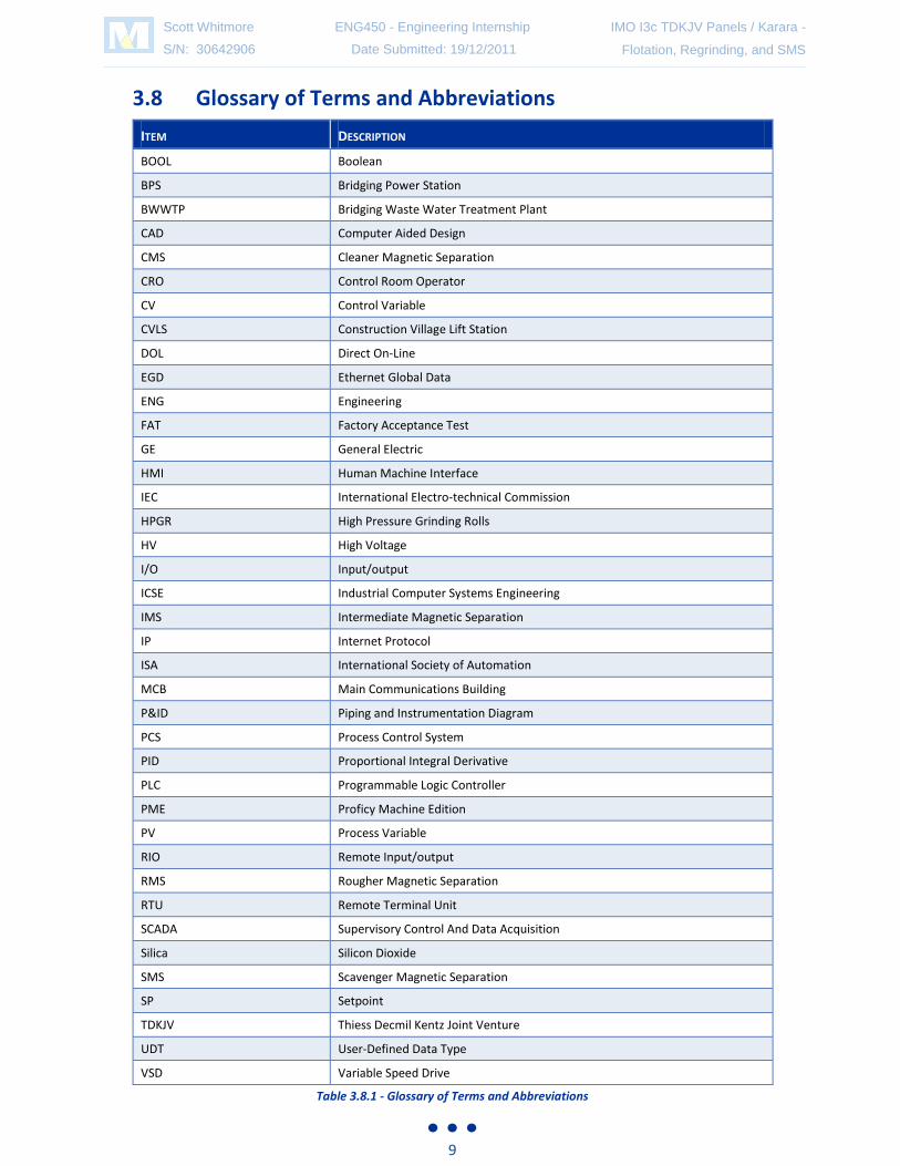


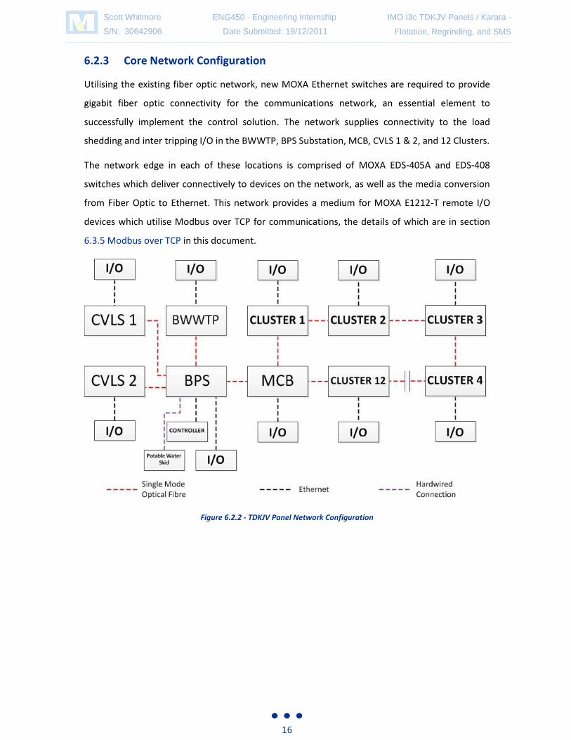


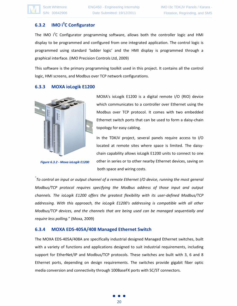


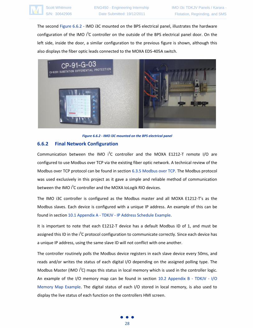
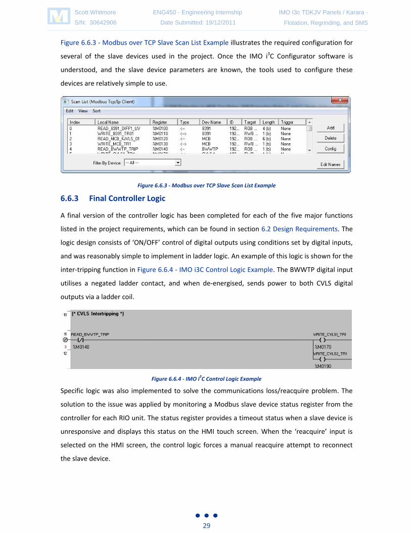

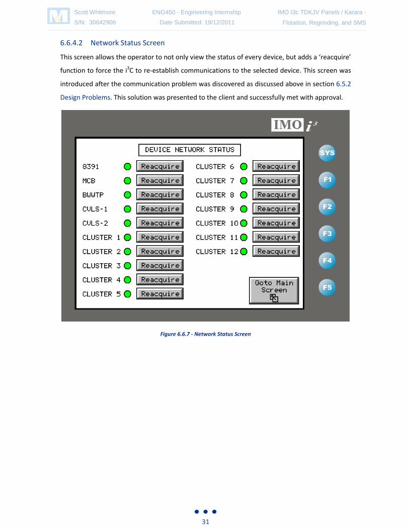


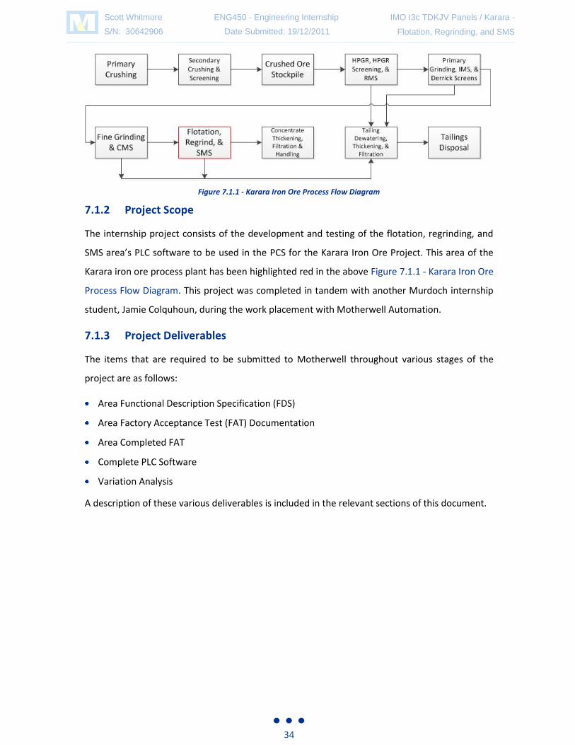


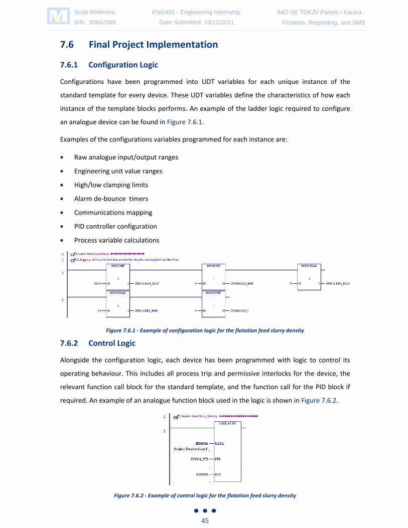

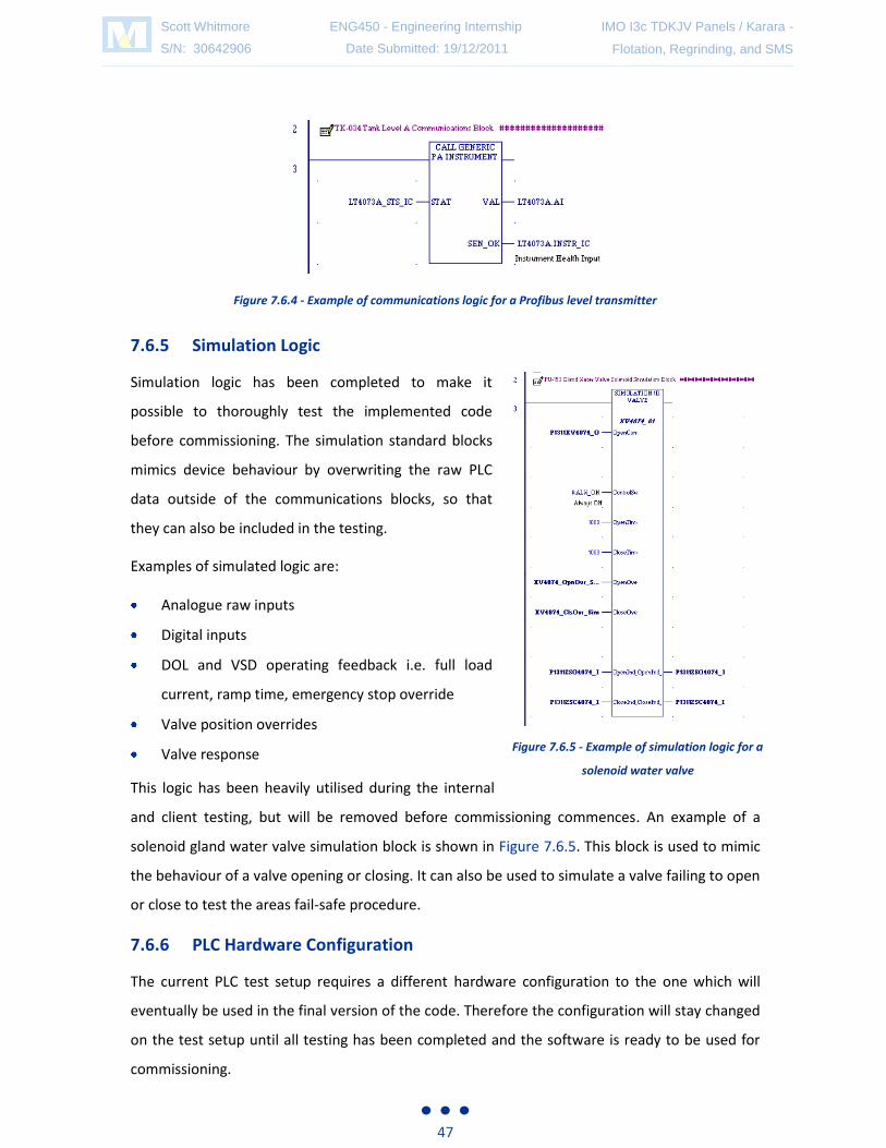
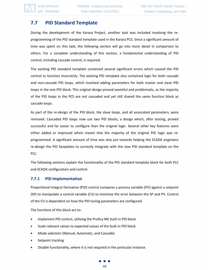


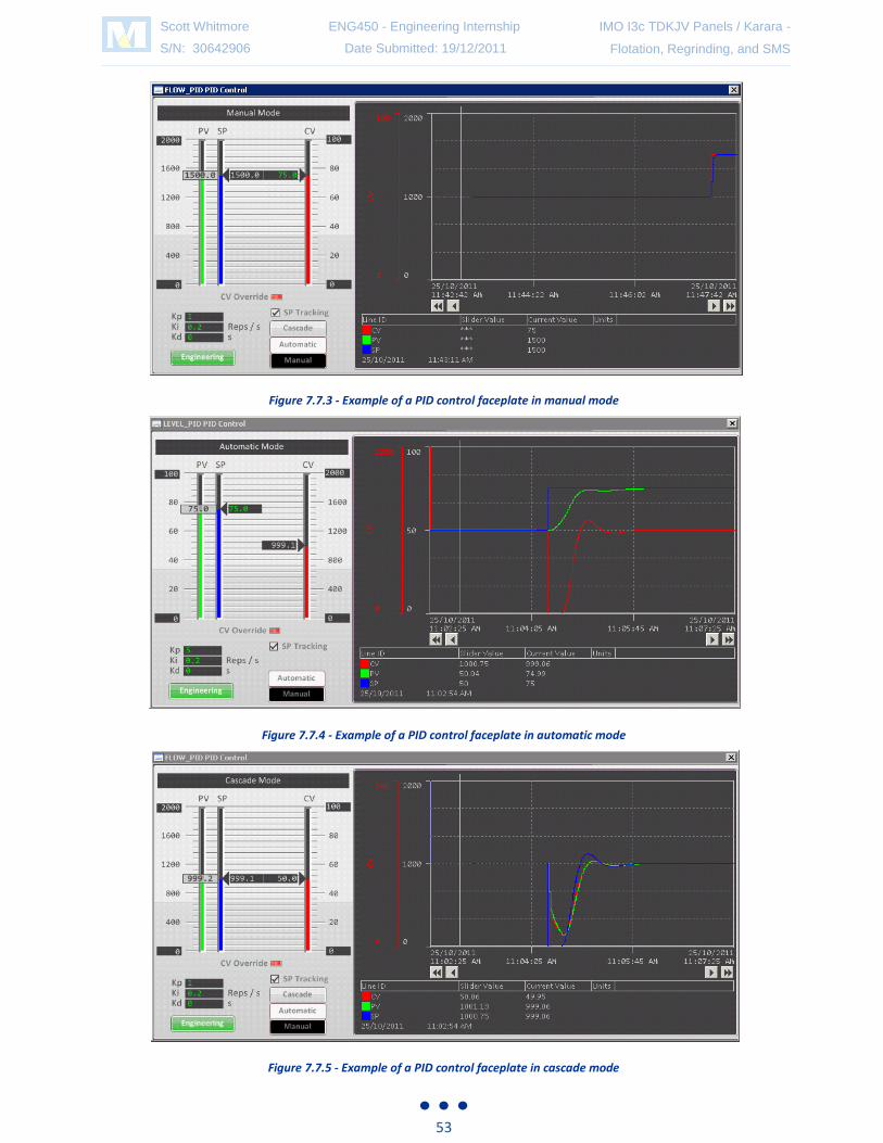


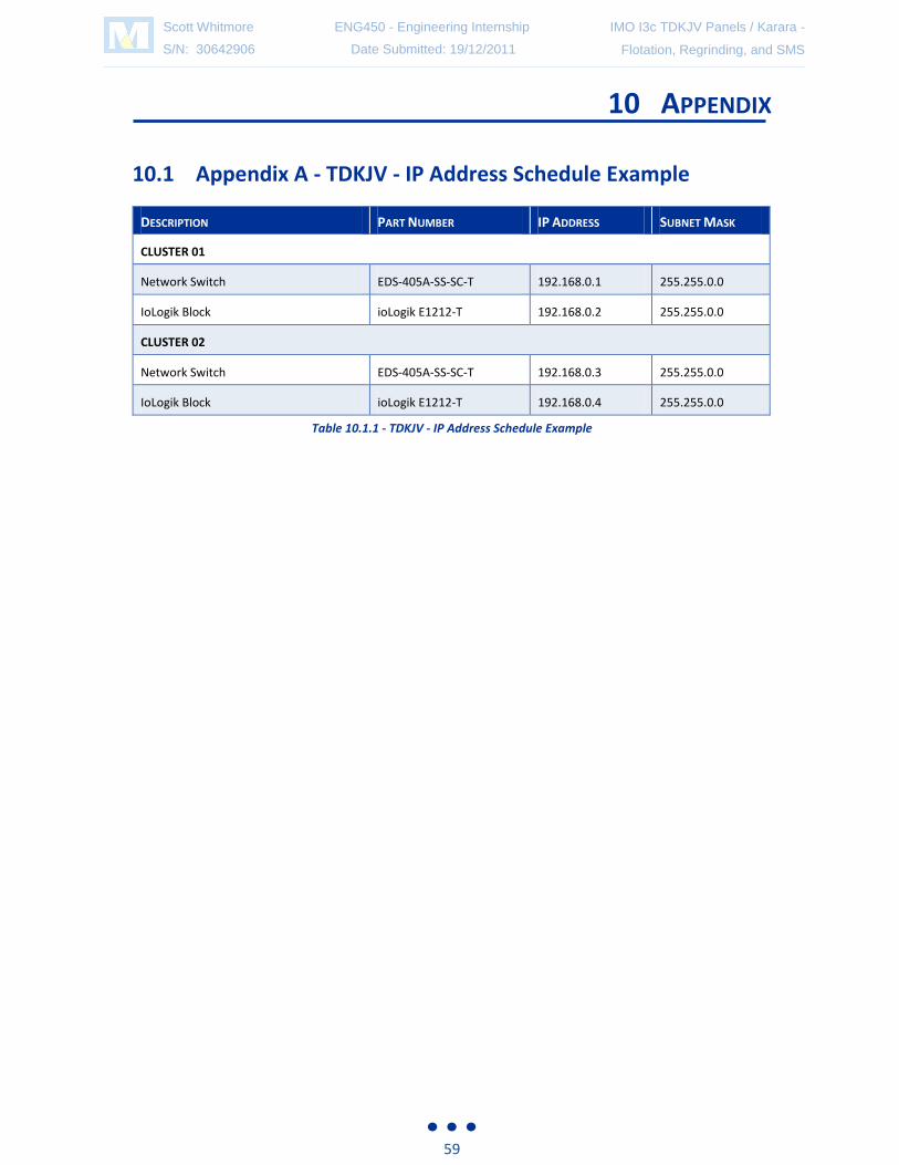
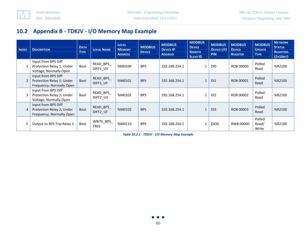

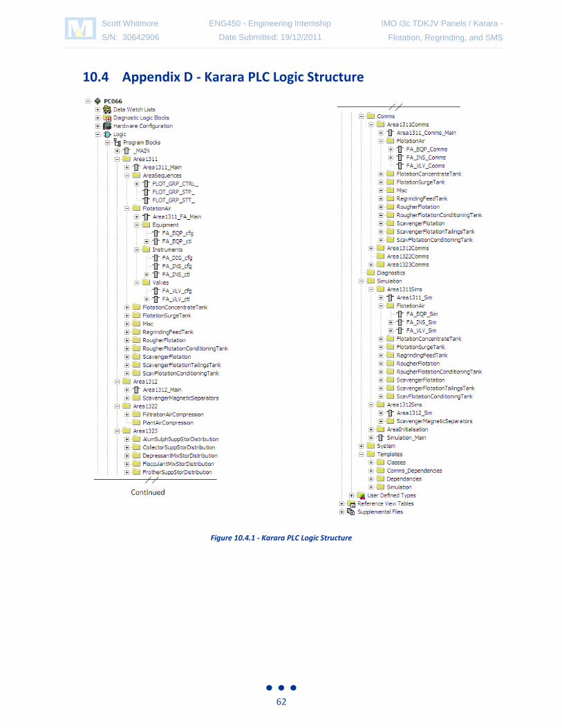


![MIPI I3C Interface –Advanced Features...Delay Time [DT] in-band, via I3C bus ALL READ IN SYNC Sequence Repetition Period Adjustable [0.2 ; 5 sec], 1 sec nominal S equnc rpats T_Ph](https://static.documents.pub/doc/80x56/5fde1bbeaca105702d31fc2a/mipi-i3c-interface-aadvanced-features-delay-time-dt-in-band-via-i3c-bus.jpg)


