RSSB impact assessment: RIS-0737-CCS and GKRT0045 Issue: Final Page 1 of 23 Impact assessment for changes to Railway Group Standard Version: Final Date: January 2016 _________________________________________________________________________ Relevant Railway Group Standards Title: Signal Sighting Assessment Requirements Number: RIS-0737-CCS Issue: One Synopsis: This standard sets out the assessment process that is used to confirm route compatibility of lineside signalling system assets with train operations. Title: Lineside Signals, Indicators and Layout of Signals Number: GKRT0045 Issue: Five Synopsis: This document defines the configuration and layout of lineside signalling equipment that is used to convey information to infrastructure managers operating stations, and railway undertaking personnel. Withdrawn document Title: Signal Positioning and Visibility Number: GERT8037 Issue: One Synopsis: This document mandates the requirements for positioning signals and indicators to ensure adequate viewing and clarity of meaning for drivers. 1 Executive summary A new Rail Industry Standard (RIS) RIS-0737-CCS issue one Signal Sighting Assessment Requirements, sets out the assessment process to be used to confirm route compatibility of lineside signalling system assets with the trains that operate on the route and the procedures applicable to the train driving and train dispatch tasks. It has been prepared to replace GERT8037 issue one Signal Positioning and Visibility. It is considered that the content of RIS-0737-CCS issue one encompasses the intent of GERT8037 issue one and will enable the hazards associated with incompatibility between a lineside signalling asset and the trains that operate on the route and the procedures applicable to train driving and dispatch staff to be managed. 2 Initiators of change The existing Railway Group Standard (RGS) GERT8037 issue one, which was published in December 2003, sets out the requirements for positioning signals and indicators to ensure adequate viewing and clarity of meaning for drivers. With the introduction of the Railway Group Standards Code and the need for requirements to be in the form of National Technical Rules (NTRs) or National Safety Rules (NSRs) it was necessary to review and revise the requirements in GERT8037 issue one. Uncontrolled When Printed
Transcript
RSSB impact assessment: RIS-0737-CCS and GKRT0045 Issue: Final
Page 1 of 23
Impact assessment for changes to Railway Group Standard
Version: Final
Date: January 2016
_________________________________________________________________________Relevant Railway Group Standards
Title: Signal Sighting Assessment Requirements
Number: RIS-0737-CCS Issue: One
Synopsis: This standard sets out the assessment process that is used to confirm route compatibility of lineside signalling system assets with train operations.
Title: Lineside Signals, Indicators and Layout of Signals
Number: GKRT0045 Issue: Five
Synopsis: This document defines the configuration and layout of lineside signalling equipment that is used to convey information to infrastructure managers operating stations, and railway undertaking personnel.
Withdrawn document
Title: Signal Positioning and Visibility
Number: GERT8037 Issue: One
Synopsis: This document mandates the requirements for positioning signals and indicators to ensure adequate viewing and clarity of meaning for drivers.
1 Executive summary
A new Rail Industry Standard (RIS) RIS-0737-CCS issue one Signal Sighting Assessment Requirements, sets out the assessment process to be used to confirm route compatibility of lineside signalling system assets with the trains that operate on the route and the procedures applicable to the train driving and train dispatch tasks. It has been prepared to replace GERT8037 issue one Signal Positioning and Visibility.
It is considered that the content of RIS-0737-CCS issue one encompasses the intent of GERT8037 issue one and will enable the hazards associated with incompatibility between a lineside signalling asset and the trains that operate on the route and the procedures applicable to train driving and dispatch staff to be managed.
2 Initiators of change The existing Railway Group Standard (RGS) GERT8037 issue one, which was published in December 2003, sets out the requirements for positioning signals and indicators to ensure adequate viewing and clarity of meaning for drivers. With the introduction of the Railway Group Standards Code and the need for requirements to be in the form of National Technical Rules (NTRs) or National Safety Rules (NSRs) it was necessary to review and revise the requirements in GERT8037 issue one.
Uncontrolled When Printed
RSSB impact assessment: RIS-0737-CCS and GKRT0045 Ref: 16 IA07 Issue: Final
Page 2 of 23
2.1 Post consultation
The content in RIS-0737-CCS issue one was consulted on as RGS GERT8101 issue one and associated Guidance Note (GN) GEGN8601 issue one. Following the introduction of the Standards Strategy in December 2015 the suitability of GERT8101 issue one to be published as an NSR has been reviewed using the ‘Rule Management Tool’ provided in Annex 3 to the final report of the European Commission’s Task Force on NSRs. The review concluded that the requirements in GERT8101 issue one were not suitable to be retained as NSRs and could not therefore be progressed for publication in an RGS. Although not qualifying to be classified as an NSR, GERT8037 issue one is considered to contain valid requirements and has therefore been re-designated as a RIS, which also incorporates the rationale for the requirements and relevant guidance. This approach is recognised in section 3.3, ‘Transition process’, in the Task Force’s final report where it is clarified that:
‘Those documents which are not considered to be NSRs anymore may remain valid. However it is necessary to revise and change their status accordingly’.
The signal sighting assessment requirements in RIS-0737-CCS issue one cannot be assessed at a Network level owing to the dependency on the operating context at specific locations. The requirements are relevant to route compatibility assessments and are consistent with the application of the common safety method on risk evaluation and assessment (CSM RA) to changes affecting signal sighting before the change is put into use.
3 Key changes and implications for industry
RIS-0737-CCS issue one sets out the assessment process used to confirm route compatibility of lineside signalling system assets and vehicles in the operational context. It has been prepared to replace GERT8037 issue one, which will be withdrawn in its entirety.
For completeness, a number of requirements in GKRT0045 issue four, which are related to the signal sighting assessment process, have been transferred into RIS-0737-CCS issue one. Also, one requirement in GERT8037 issue one that is not directly relevant to the signal sighting assessment process has been transferred to GKRT0045. GKRT0045 issue four has been replaced by GKRT0045 issue five to incorporate these changes.
The requirements in RIS-0737-CCS issue one are relevant to the assessment of compatibility of lineside signalling system assets with trains that operate on the route and the procedures applicable to the train driving and train dispatch tasks.
The requirements in RIS-0737-CCS issue one have been developed from first principles with drafting support provided by industry representatives who have experience of managing signal sighting assessment activities and applying the signal sighting assessment process on the Great Britain (GB) mainline railway.
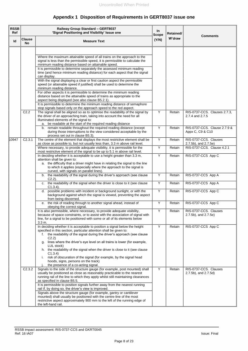
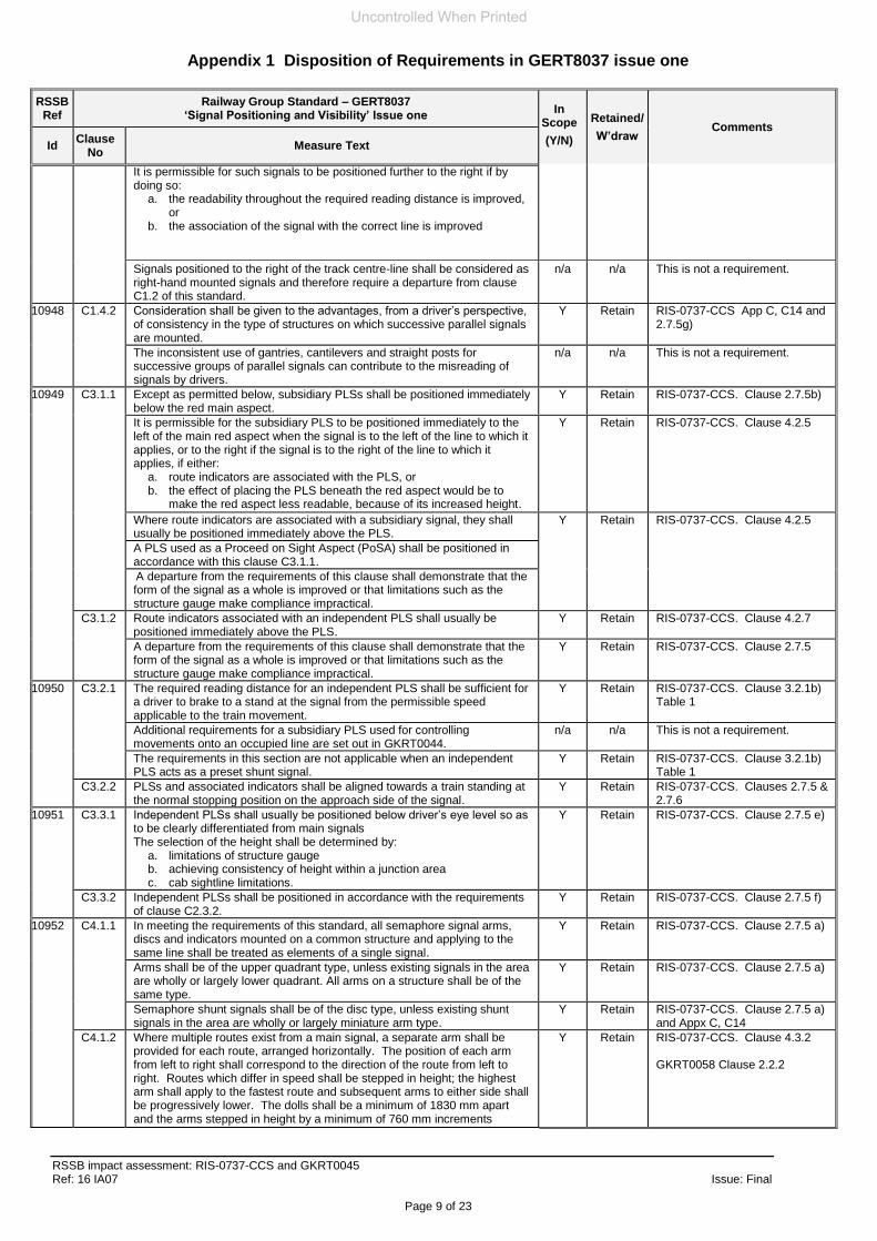
Appendix 1 to this impact assessment sets out the disposition of the requirements in GERT8037 issue one, identifying where they have been addressed in RIS-0737-CCS issue one and GKRT0045 issue five.
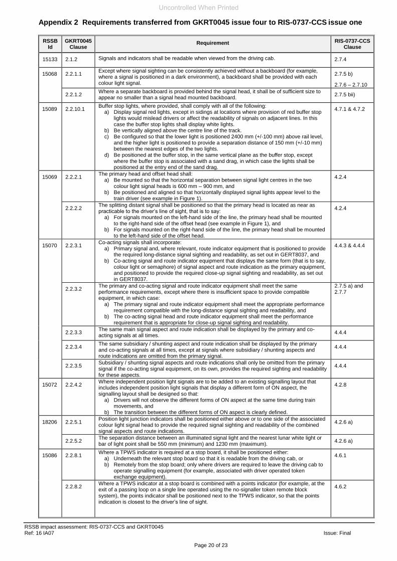
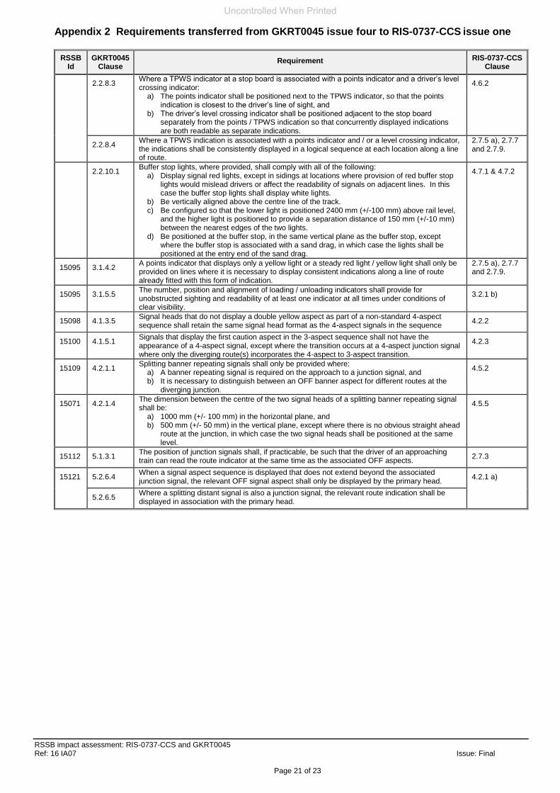
Appendix 2 identifies those requirements that have been withdrawn from GKRT0045 issue four and addressed in RIS-0737-CCS issue one.
Appendix 3 sets out new requirements that have been identified through the drafting process to be required for completeness.
RIS-0737-CCS issue one is considered to encompass the intent of GERT8037 issue one and the hazards it addresses associated with deficiencies in the presentation of the information provided by the lineside signalling assets.
Uncontrolled When Printed
RSSB impact assessment: RIS-0737-CCS and GKRT0045 Ref: 16 IA07 Issue: Final
Page 3 of 23
3.1 Post-consultation As a result of consultation comments the document has been rewritten to specify the process for managing planned changes to the railway that affect signal sighting. The emphasis of the requirements have been changed to be consistent with a proposer applying the CSM RA to changes affecting signal sighting before the change is put into use. Guidance has been added to the start of Parts 2, 3 and 4 of RIS-0737-CCS issue one to explain how the requirements in each part are consistent with the application of the CSM RA. Guidance is also included to explain that the requirements in the standard can also be used to assess signal sighting of existing assets. The majority of changes to the RIS involved providing additional guidance or rewording requirements, for clarification. The main change includes replacing some unnecessarily detailed and potentially restrictive requirements with a higher level requirement which, while addressing the same need and managing the same potential hazards, allows more flexibility on how this can be achieved. The detail of the original requirements has been retained and incorporated in guidance to explain how the higher level requirement could be met. A high-level requirement has been included in clause 2.6.2 to identify the topics to be addressed in a signal sighting assessment plan. The intent of the requirement is to make information available to stakeholders before a signal sighting assessment takes place. The information that is to be provided is needed to inform the stakeholders’ understanding of the scope of the assessment and the assessment method that will be used, as well as to identify the roles and responsibilities of the members of the signal sighting committee. The introduction of the high-level requirement removes the need for a number of prescriptive requirements and allows flexibility in achieving the appropriate level of detail that may be needed for signal sighting assessments depending on the operational context. For consistency, speed units in km/h have been replaced by mph because, on the existing railway, train speeds are displayed in mph where lineside signalling systems are provided. A change has been made to replace some references to minimum readable distance performance with minimum response times. The basic response times that are to be used to derive the minimum response times are specified as requirements in clause 3.4. This has the benefit that the attainable train speed may be taken into consideration, which could potentially allow more efficient signalling layouts. In addition, some signs need only be recognised without having to be read by the driver, including: platform stop markers (AK104), mid platform marker (AK105), banner repeaters, splitting banner repeaters (AK105) and whistle boards (AK203z) as well as those signs where the information presented is one of two alternatives. As RISs do not include compliance dates, the Control Command and Signalling Standards Committee (CCS SC) agreed (minute number 15/CCS10/315) that the early publication of RIS-0737-CCS issue one would be beneficial rather than delaying its publication to accommodate a trial of the signal sighting assessment process, which was the intent when the requirements were to be published in GERT8101 issue one. The early publication of the signal sighting assessment process will allow infrastructure managers and railway undertakings to undertake controlled application of the revised signal sighting assessment process to selected infrastructure projects.
4 Predicted impacts
The new RIS-0737-CCS issue one provides a consistent approach for assessing the route compatibility of signalling system assets and train operations on the GB network and is therefore considered to be beneficial to the industry by specifying an approach
Uncontrolled When Printed
RSSB impact assessment: RIS-0737-CCS and GKRT0045 Ref: 16 IA07 Issue: Final
Page 4 of 23
which enables the hazards associated with incompatibility to be managed. It is considered that, although the assessment process may have changed in detail, the overall framework it provides is consistent with existing practice and should be familiar to those undertaking signal sighting assessments on the GB mainline railway and require limited training and briefing of signal sighting committees’ chairs and members.
4.1 Post-consultation
It is considered that the changes made following consultation provide better clarity, will allow more flexibility in the signal sighting assessment process and allow the operational context to be taken into account more effectively. The changes are considered to be safety neutral and will enable the hazards associated with incompatibility between a lineside signalling asset and vehicles in the operational context to be managed.
Uncontrolled When Printed
Appendix 1 Disposition of Requirements in GERT8037 issue one
RSSB impact assessment: RIS-0737-CCS and GKRT0045 Ref: 16 IA07 Issue: Final
Page 5 of 23
RSSB Ref
Railway Group Standard – GERT8037 ‘Signal Positioning and Visibility’ Issue one
In Scope
(Y/N)
Retained/
W’draw Comments
Id Clause
No Measure Text
10940 B5.7 The longitudinal position of signals shall be selected so as to ensure that they meet the readability requirements set out elsewhere in this standard, whilst also taking into account the requirements for:
a) signal spacing (see GKRT0034) b) the provision of signals (see GKRT0032) c) the positioning of signals used to control movements onto occupied
lines (see GKRT0044).
n/a n/a This is not a requirement.
C1.1.1 Where lines running parallel to each other are signalled in the same direction and drivers on one line can see the signal(s) on the parallel line(s), the signals for each line shall normally be placed so as to be at the same longitudinal positions as those on the parallel lines. This is called ‘parallel positioning’ of signals.
Y Retain GKRT0045 issue 5 3.1.1.5
Signals shall be regarded as parallel if they are within 20 m of each other longitudinally.
Where lines running parallel to each other are signalled in the same direction but signals are not provided on each line, particular consideration shall be given to ensure that the risk of driver confusion or misread is minimised.
Y Retain RIS-0737-CCS App C section C12
Where lines that are operated as separate routes run parallel (for example, the DC lines alongside the West Coast Main Line, or LUL lines adjacent to Network Rail controlled infrastructure), this section applies to each route individually, and not to the set of parallel routes. Nevertheless, consideration shall be given to the risk of drivers on either route erroneously obeying signals that apply to the adjacent route.
A departure from the requirement for signals to be positioned to appear in parallel shall demonstrate, as a minimum, that:
a) during the approach to the signals, the driver is unlikely to be confused as to the position of the signals or which signal to obey. In particular, the ‘crossing-over effect’ (in which the relative positions of the signals appears to change during the approach) shall not occur
b) the overrun risks associated with the non-parallel positions are acceptably low.
N W’draw This requirement is out of scope of RGSs.
10941 B5.8 Requirements for structure clearances relating to the positioning of new, altered and temporary infrastructure are set out in GC/RT5212. Additional requirements for personal safety in respect of clearances are set out in GC/RT5203.
n/a n/a This is not a requirement.
Signals and signal structures shall be positioned so as to meet the requirements of GERT8025.
n/a n/a This is not a requirement.
C1.2.1 Each signal shall be positioned laterally as follows: a) on the left-hand side of the line as seen in the direction of travel to
which the signal applies, except as permitted by clause C1.2.2
Y Retain RIS-0737-CCS. Clause 2.7.5c
b) so that drivers on all lines readily associate the signal with the line to which it applies and not with any other line.
Y Retain RIS-0737-CCS App C C3
C1.2.2 A departure from the requirement for signals to be positioned on the left-hand side of the line shall demonstrate, as a minimum, that:
a) the readability is improved for trains approaching the signal and SPAD risk is reduced
Y Retain RIS-0737-CCS. Clause 2.8.1c
b) for stop signals, the signal is readable by drivers of trains stationary in the normal stopping position at the signal (clause only applicable to stop signals).
Y Retain RIS-0737-CCS App A, A7
c) there is no line immediately to the right of the signal, such that drivers on either line might associate the signal with that line rather than with the line to which it actually applies (signals on lines separated by an island platform can usually be regarded as meeting this criterion).
Y Retain RIS-0737-CCS Appx C, C12
10942 B5.3 So far as is reasonably practicable, there shall be no interruption of the driver’s view of a signal during the minimum reading time.
Y Retain RIS-0737-CCS. Clause 3.2.3
An assessment shall be made of any remaining interruptions to demonstrate that they do not give rise to an unacceptable risk of the driver disregarding or misreading the signal.
When determining where the minimum reading time commences, referred to as the minimum reading distance (MRD), a distance equivalent to the length of any interruptions shall be added.
C1.3.1 Where the achievable reading distance (see clause B5.5) is initially assessed as less than the minimum reading distance (see clause B5.4), then mitigating measures shall be considered in order to increase the reading time available or to reduce the minimum required.
Y Retain RIS-0737-CCS. Clause 2.7.3
Consideration shall be given to hazards generated by the introduction of the mitigating measures.
Where the hazards introduced are considered more significant than the improvements to reading distance generated, the mitigating measure shall
Uncontrolled When Printed
Appendix 1 Disposition of Requirements in GERT8037 issue one
RSSB impact assessment: RIS-0737-CCS and GKRT0045 Ref: 16 IA07 Issue: Final
Page 6 of 23
RSSB Ref
Railway Group Standard – GERT8037 ‘Signal Positioning and Visibility’ Issue one
In Scope
(Y/N)
Retained/
W’draw Comments
Id Clause
No Measure Text
not be introduced and other options shall be developed.
A departure from this requirement to permit an achievable reading distance less than the minimum reading distance, shall demonstrate, as a minimum, that
a) it is not reasonably practicable to increase the achievable reading distance
b) the difference between that which is achievable and the minimum reading distance is tolerable
When an acceptable achievable reading distance has been determined this shall be recorded as the required reading distance.
(GERT8034 sets out requirements to maintain the required reading distance for the life of the signal.).
n/a n/a This is not a requirement.
C1.3.2 For signals capable of displaying a stop aspect, all elements of the signal shall be readable from the driving cab with no interruption of view between 40 m from the signal and the closest point at which a driver is expected to bring his train to a stand at the signal at danger.
Y Retain RIS-0737-CCS. Clauses 2.7.6 and 3.2.2
It is permissible to apply other measures, such as described in section C5.2, in order to meet this requirement.
n/a n/a This is not a requirement.
Where the signal is fitted with a device that offers a means of enhanced close-up viewing (for example a close up viewing segment) the device shall be orientated to optimise the readability over this distance.
Y Retain RIS-0737-CCS. Clauses 2.7.6 and 3.2.2
Where planned stopping points are to be closer than 15 m before the signal, a vision plot, identifying the limitations caused by cab sightlines of the relevant types of rolling stock, shall be carried out.
Y Retain RIS-0737-CCS. Clauses 2.7.6 and 3.2.2
Section C6 sets out the special requirements for platform starting signals. n/a n/a This is not a requirement.
C1.3.3 So far as is reasonably practicable, signals shall be positioned and aligned so as not to cause confusion in the correct observation and interpretation of other signals by drivers on other lines, whilst ensuring that a driver has adequate visibility of signals on their line.
Y Retain RIS-0737-CCS Appx B
On parallel lines signalled in the same direction, consideration shall be given to the provision of a means by which a driver can more readily identify the signal that is applicable to their train. This is particularly important on lines with three or more parallel signals, or where a junction is unusually complex.
Y Retain RIS-0737-CCS Appx C, C12
C1.3.4 Consideration shall be given to the risk of a driver reading-through to a signal beyond that which should next be obeyed and which might reasonably be expected to be displaying a less restrictive aspect (typically beyond a junction or level crossing).
Y Retain RIS-0737-CCS. Clause 2.7.9
Where this risk is considered unacceptable, measures shall be introduced (such as reducing the conspicuity of the forward signal or applying special controls to the signal aspect) to mitigate the risk (see GKRT0060).
Y Retain RIS-0737-CCS Appx C, C12
10943 C1.4.1 Successive signals for the same direction of traffic flow shall be reasonably consistent in form, in order to facilitate correct observation by the driver of the information presented.
Y Retain RIS-0737-CCS. Clause 2.7.9
Consideration shall be given to the form of new, modified and existing unaltered signals preceding/following the new or modified signals. The following factors shall be considered:
a) the relative position of elements of signals b) the choice of route indicator types c) the lateral position of signals d) the relative position of parallel signals.
Y Retain RIS-0737-CCS Appx A
Colour light and semaphore elements shall not be intermixed on a signal, except that it is permissible to use alphanumeric route indicators in conjunction with semaphore stop signals.
Y d GKRT0058 Part 2. Tables 1, 2 and 3.
A departure from this requirement to permit inconsistent signal forms shall demonstrate, as a minimum, that:
a) the resulting signals do not introduce any foreseeable driver error b) the inconsistency has been introduced to improve drivers’
understanding.
Y Retain . RIS-0737-CCS Appx C, C14
10944 B5.10 The design of the signal and associated structure shall take into consideration the proposed arrangements for the maintenance and alignment checks of the signal, and shall incorporate any features necessary to allow access to the equipment for such purposes.
N W’draw Out requirement is out of scope of RGSs.
10945 C2.1.1 Main colourlight signal heads comprising more than one element shall usually be mounted vertically.
Y Retain RIS-0737-CCS. Clauses 4.2.1a), 2.7.5 b), f) and g). GKRT0058 Table A7.
Where necessary, for visibility purposes or because of constraints on space, it is permissible to mount the elements other than in a vertical array, provided that any double yellow aspect, and any flashing double yellow aspect, continues to be displayed vertically.
Uncontrolled When Printed
Appendix 1 Disposition of Requirements in GERT8037 issue one
RSSB impact assessment: RIS-0737-CCS and GKRT0045 Ref: 16 IA07 Issue: Final
Page 7 of 23
RSSB Ref
Railway Group Standard – GERT8037 ‘Signal Positioning and Visibility’ Issue one
In Scope
(Y/N)
Retained/
W’draw Comments
Id Clause
No Measure Text
If more than one element is used to display aspects, the order of proximity of lights to the driver’s eye as he passes the signal shall be as follows
a) red aspect light closest b) first yellow aspect light c) green aspect light d) second yellow aspect light (required only for double yellow aspect
and flashing double yellow aspect).
Where any of the four elements listed above are not provided, or are combined into a single unit, the order described above shall be maintained by the remaining elements.
Exceptionally, it is permissible for a signal required to show red, yellow and double yellow only, to have the red light separating the two yellows, but only if the red aspect remains near driver’s eye level so that the sighting of the aspect cannot be obscured by signal hoods.
C2.1.2 Position light junction indicators (PLJIs) shall usually be positioned with the pivot light directly above the main aspects.
Y Retain RIS-0737-CCS. Clause 4.2.6
It is permissible for the indicators to be positioned immediately to the side of the main signal (left or right), but only where there is no other way of ensuring adequate readability.
Y Retain RIS-0737-CCS. Clause 4.2.6
Where a PLJI is positioned to the side of the main signal, the pivot light shall be positioned adjacent to the red aspect.
Y Retain RIS-0737-CCS. Clause 4.2.6
Position indicators 1, 2 and 3 shall be placed only to the left of the main signal, and position indicators 4, 5 and 6 only to the right (see GKRT0031 for details of position notation).
Y Retain RIS-0737-CCS. Clause 4.2.6
It is permissible for alphanumeric route indicators to be positioned either above, or immediately to the side of the main signal, which ever gives the optimum readability.
Y Retain RIS-0737-CCS. Clause 4.2.7
Where an alphanumeric route indicator is positioned to the side of the main signal, it shall be positioned to the left of the main signal if the signal is on the left-hand side of the line, and to the right of the main signal if the signal is to the right-hand side of the line
Y Retain RIS-0737-CCS. Clause 4.2.7
10946 B5.2.1 Except as permitted below, the assessed minimum reading time, as defined in section B3, shall be determined for each signal.
Y Retain RIS-0737-CCS. Clause 3.2.1a
An assessed minimum reading time is not required for the following types of signal:
a) signals where trains can only start from rest (for example a terminal platform starter)
b) signals that can only display a stop aspect (for example a fixed red or a stop board)
c) signals where all approaching trains are required to proceed at a speed which allows them to stop on sight (for example, independent PLS)
Y Retain RIS-0737-CCS. Clause 3.2.1b
For signals not requiring an assessed minimum reading time, a minimum reading distance shall be determined that ensures that any approaching train is capable of stopping at the signal.
Y Retain RIS-0737-CCS. Clause 3.3.1
B5.2.2 The assessed minimum reading time shall be no less than eight seconds travelling time before the signal.
Y Retain RIS-0737-CCS. Clause 3.3.1
The assessed minimum reading time shall be greater than eight seconds where there is an increased likelihood of misread or failure to observe.
Circumstances where this applies include, but are not necessarily limited to, the following
a. the time taken to identify the signal is longer (for example, because the signal being viewed is one of a number of signals on a gantry, or because the signal is viewed against a complex background)
b. the time taken to interpret the information presented by the signal is longer (for example, because the signal is capable of presenting route information for a complex layout ahead)
c. there is a risk that the need to perform other duties could cause distraction from viewing the signal correctly (for example, the observance of lineside signs, a station stop between the caution and stop signals, or DOO (P) duties)
d. the control of the train speed is influenced by other factors (for example, anticipation of the signal aspect changing).
The assessed minimum reading time shall be determined using a structured format approved by the infrastructure controller
N W’draw This requirement is out of scope of RGSs.
B5.4 The location on the train’s approach to the signal at which the assessed minimum reading time commences (known as the minimum reading distance) shall usually be calculated using the permissible speed applicable at that location.
Y Retain RIS-0737-CCS. Clause 3.2.1a
Uncontrolled When Printed
Appendix 1 Disposition of Requirements in GERT8037 issue one
RSSB impact assessment: RIS-0737-CCS and GKRT0045 Ref: 16 IA07 Issue: Final
Page 8 of 23
RSSB Ref
Railway Group Standard – GERT8037 ‘Signal Positioning and Visibility’ Issue one
In Scope
(Y/N)
Retained/
W’draw Comments
Id Clause
No Measure Text
Where the maximum attainable speed of all trains on the approach to the signal is less than the permissible speed, it is permissible to calculate the minimum reading distance based on attainable speed.
It is permissible to determine separately the assessed minimum reading time (and hence minimum reading distance) for each aspect that the signal can display.
With the signal displaying a clear or first caution aspect the permissible speed (or attainable speed if justified) shall be used to determine the minimum reading distance.
For other aspects it is permissible to determine the minimum reading distance based on the attainable speed of trains as appropriate to the aspect being displayed (see also clause B5.2.1).
It is permissible to determine the minimum reading distance of semaphore stop signals based only on the approach speed to the red aspect.
C2.2 The signal shall be aligned so as to optimise the readability of the signal by the driver of an approaching train, taking into account the need for all illuminated elements of the signal to:
a. be readable at the start of the required reading distance
Y Retain RIS-0737-CCS. Clauses 2.7.3, 2.7.4 and 2.7.5
b. remain readable throughout the required reading distance (except during those interruptions to the view considered acceptable by the process set out in clause B5.3).
10947 C2.3.1 The centre of the element that displays the most restrictive element shall be as close as possible to, but not usually less than, 3.3 m above rail level.
Y Retain RIS-0737-CCS. Clauses 2.7.5b), and 2.7.5e)
Where necessary, to provide adequate visibility, it is permissible for the most restrictive element of the signal to be up to 5.1 m above rail level.
Y Retain RIS-0737-CCS. Clause 4.2.1
In deciding whether it is acceptable to use a height greater than 3.3 m, attention shall be given to:
a. the difficulty that a driver might have in relating the signal to the line to which it applies (especially where the approach to the signal is curved, with signals on parallel lines).
Y Retain RIS-0737-CCS App C
b. the readability of the signal during the driver’s approach (see clause C2.2).
Y Retain RIS-0737-CCS App A
c. the readability of the signal when the driver is close to it (see clause C1.3.4).
Y Retain RIS-0737-CCS App A
d. possible problems with incident or background sunlight, or with the background against which the signal is viewed, preventing the aspect from being discerned.
Y Retain RIS-0737-CCS App C
e. the risk of reading through to another signal ahead, instead of obeying the correct signal.
Y Retain RIS-0737-CCS App C
It is also permissible, where necessary, to provide adequate visibility, because of space constraints, or to assist with the association of signal with line, for a signal to be positioned with some or all of its elements below 3.3 m.
Y Retain RIS-0737-CCS. Clauses 2.7.5b), and 2.7.5e)
In deciding whether it is acceptable to position a signal below the height specified in this section, particular attention shall be given to:
f. the readability of the signal during the driver’s approach (see clause C2.2)
g. lines where the driver’s eye level on all trains is lower (for example, LUL stock)
h. the readability of the signal when the driver is close to it (see clause C1.3.4)
i. risk of obscuration of the signal (for example, by the signal head hoods, signs, persons on the track)
j. the presence of a co-acting signal.
Y Retain RIS-0737-CCS App C
C2.3.2 Signals to the side of the structure gauge (for example, post mounted) shall usually be positioned as close as reasonably practicable to the nearest running rail of the line to which they apply whilst still maintaining clearances as specified in clause B5.5.
Y Retain RIS-0737-CCS. Clauses 2.7.5b), and 2.7.5d)
It is permissible to position signals further away from the nearest running rail if, by doing so, the driver’s view is improved.
Signals above the structure gauge (for example, gantry or cantilever mounted) shall usually be positioned with the centre-line of the most restrictive aspect approximately 900 mm to the left of the running edge of the left-hand rail.
Uncontrolled When Printed
Appendix 1 Disposition of Requirements in GERT8037 issue one
RSSB impact assessment: RIS-0737-CCS and GKRT0045 Ref: 16 IA07 Issue: Final
Page 9 of 23
RSSB Ref
Railway Group Standard – GERT8037 ‘Signal Positioning and Visibility’ Issue one
In Scope
(Y/N)
Retained/
W’draw Comments
Id Clause
No Measure Text
It is permissible for such signals to be positioned further to the right if by doing so:
a. the readability throughout the required reading distance is improved, or
b. the association of the signal with the correct line is improved
Signals positioned to the right of the track centre-line shall be considered as right-hand mounted signals and therefore require a departure from clause C1.2 of this standard.
n/a n/a This is not a requirement.
10948 C1.4.2 Consideration shall be given to the advantages, from a driver’s perspective, of consistency in the type of structures on which successive parallel signals are mounted.
Y Retain RIS-0737-CCS App C, C14 and 2.7.5g)
The inconsistent use of gantries, cantilevers and straight posts for successive groups of parallel signals can contribute to the misreading of signals by drivers.
n/a n/a This is not a requirement.
10949 C3.1.1 Except as permitted below, subsidiary PLSs shall be positioned immediately below the red main aspect.
Y Retain RIS-0737-CCS. Clause 2.7.5b)
It is permissible for the subsidiary PLS to be positioned immediately to the left of the main red aspect when the signal is to the left of the line to which it applies, or to the right if the signal is to the right of the line to which it applies, if either:
a. route indicators are associated with the PLS, or b. the effect of placing the PLS beneath the red aspect would be to
make the red aspect less readable, because of its increased height.
Y Retain RIS-0737-CCS. Clause 4.2.5
Where route indicators are associated with a subsidiary signal, they shall usually be positioned immediately above the PLS.
Y Retain RIS-0737-CCS. Clause 4.2.5
A PLS used as a Proceed on Sight Aspect (PoSA) shall be positioned in accordance with this clause C3.1.1.
A departure from the requirements of this clause shall demonstrate that the form of the signal as a whole is improved or that limitations such as the structure gauge make compliance impractical.
C3.1.2 Route indicators associated with an independent PLS shall usually be positioned immediately above the PLS.
Y Retain RIS-0737-CCS. Clause 4.2.7
A departure from the requirements of this clause shall demonstrate that the form of the signal as a whole is improved or that limitations such as the structure gauge make compliance impractical.
Y Retain RIS-0737-CCS. Clause 2.7.5
10950 C3.2.1 The required reading distance for an independent PLS shall be sufficient for a driver to brake to a stand at the signal from the permissible speed applicable to the train movement.
Y Retain RIS-0737-CCS. Clause 3.2.1b) Table 1
Additional requirements for a subsidiary PLS used for controlling movements onto an occupied line are set out in GKRT0044.
n/a n/a This is not a requirement.
The requirements in this section are not applicable when an independent PLS acts as a preset shunt signal.
Y Retain RIS-0737-CCS. Clause 3.2.1b) Table 1
C3.2.2 PLSs and associated indicators shall be aligned towards a train standing at the normal stopping position on the approach side of the signal.
Y Retain RIS-0737-CCS. Clauses 2.7.5 & 2.7.6
10951 C3.3.1 Independent PLSs shall usually be positioned below driver’s eye level so as to be clearly differentiated from main signals The selection of the height shall be determined by:
a. limitations of structure gauge b. achieving consistency of height within a junction area c. cab sightline limitations.
Y Retain RIS-0737-CCS. Clause 2.7.5 e)
C3.3.2 Independent PLSs shall be positioned in accordance with the requirements of clause C2.3.2.
Y Retain RIS-0737-CCS. Clause 2.7.5 f)
10952 C4.1.1 In meeting the requirements of this standard, all semaphore signal arms, discs and indicators mounted on a common structure and applying to the same line shall be treated as elements of a single signal.
Y Retain RIS-0737-CCS. Clause 2.7.5 a)
Arms shall be of the upper quadrant type, unless existing signals in the area are wholly or largely lower quadrant. All arms on a structure shall be of the same type.
Y Retain RIS-0737-CCS. Clause 2.7.5 a)
Semaphore shunt signals shall be of the disc type, unless existing shunt signals in the area are wholly or largely miniature arm type.
Y Retain RIS-0737-CCS. Clause 2.7.5 a) and Appx C, C14
C4.1.2 Where multiple routes exist from a main signal, a separate arm shall be provided for each route, arranged horizontally. The position of each arm from left to right shall correspond to the direction of the route from left to right. Routes which differ in speed shall be stepped in height; the highest arm shall apply to the fastest route and subsequent arms to either side shall be progressively lower. The dolls shall be a minimum of 1830 mm apart and the arms stepped in height by a minimum of 760 mm increments
Y Retain RIS-0737-CCS. Clause 4.3.2 GKRT0058 Clause 2.2.2
Uncontrolled When Printed
Appendix 1 Disposition of Requirements in GERT8037 issue one
RSSB impact assessment: RIS-0737-CCS and GKRT0045 Ref: 16 IA07 Issue: Final
Page 10 of 23
RSSB Ref
Railway Group Standard – GERT8037 ‘Signal Positioning and Visibility’ Issue one
In Scope
(Y/N)
Retained/
W’draw Comments
Id Clause
No Measure Text
The following alternative forms of junction signal are permitted if their use improves clarity or consistency:
a. Junction signals arranged with multiple routing arms arranged vertically above one another. The position of each arm from top to bottom shall correspond to the direction of the route from left to right. Arms shall be a minimum of 1680 mm apart. This arrangement shall be used only where the speed differential between the fastest and slowest route is no greater than 10 mph and where the permissible speed is no greater than 40 mph.
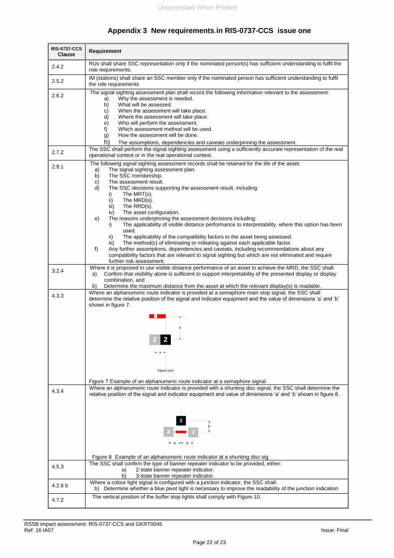
b. Junction signals arranged with a single arm and a standard alphanumeric route indicator positioned directly underneath.
Y Retain RIS-0737-CCS. Clause 4.3.3
Consideration shall be given to the risk of a bright route indicator obscuring a relatively dim signal lamp.
Y Retain RIS-0737-CCS Appx A , A1
Where stop and distant arms applying to the same route are to be mounted on the same post, the distant arm shall be positioned 1680 mm (+/- 200 mm) below the stop arm.
Y Retain RIS-0737-CCS. Clause 4.3.2
Where stop and subsidiary arms applying to the same route are to be mounted on the same post, the subsidiary signals shall be fitted 1070 mm (+/- 200mm) below the arm next above.
Where a distant signal is fitted below a stop signal, any subsidiary signal shall be fitted below the distant signal arm.
The discs / arms of shunting signals shall be arranged directly above one another and their positions from top to bottom shall correspond to the direction of the route from left to right.
Where more than one disc / arm is mounted on a single structure, all such discs / arms shall be of uniform type (that is, all discs or all arms), size and design.
Y Retain RIS-0737-CCS. Clause 2.7.5 a) and Appx C, C14
Where arms are used, they shall be spaced 1070 mm (+/- 200 mm) apart Y Retain RIS-0737-CCS. Clause 4.3.2
C4.1.3 Except as permitted below, the light intensity of all main semaphore signals shall be reasonably consistent within the area controlled by a signal box.
Y Retain RIS-0737-CCS. Clause 2.7.5 a)
It is permissible for the light intensity of a semaphore signal to be significantly greater than that of other signals controlled by the same signal box, if by doing so it improves the readability of that signal and does not increase the likelihood of drivers misreading or disregarding other signals.
10953 C4.2.1 The visibility requirements set out in section C1.3 apply to both the day and night indications of the signal.
n/a n/a This is not a requirement.
C4.2.2 The required reading distance for an independent shunting signal shall be sufficient for a driver to brake to a stand at the signal from the permissible speed applicable to the train movement.
Y Retain RIS-0737-CCS. Clause 3.2.1 b)
Additional requirements for a subsidiary shunt signal used for controlling movements onto an occupied line are set out in GKRT0044.
n/a n/a This is not a requirement
The requirements in this section are not applicable when an independent shunt signal acts as a preset shunt signal.
Y Retain RIS-0737-CCS. Clause 3.2.1 b)
10954 C4.3.1 The centre of the lowest element of the signal shall be as close as reasonably practicable to, but not below, driver’s eye level, except as permitted below.
Y Retain RIS-0737-CCS. Clause 2.7.5 b)
Where essential to provide adequate visibility, it is permissible for the signal height to be increased.
In deciding whether it is acceptable to use a greater height, attention shall be given to:
a. the difficulty that a driver could have in relating the signal to the line to which it applies (especially where the approach to the signal is curved, with signals on parallel lines)
b. the readability of the signal when the driver is close to it c. the risk of reading through to another signal ahead, instead of
obeying the correct signal.
It is permissible for subsidiary shunting signals to be ground mounted
C4.3.2 Shunting signals shall usually be positioned below driver’s eye level so as to be clearly differentiated from main signals. The selection of the height shall be determined by a. limitations of structure gauge.
a. achieving consistency of height within a junction area b. cab sightline limitations.
Y Retain RIS-0737-CCS. Clause 2.7.5
C4.3.3 The horizontal centre of the distant board or the red target of a stop board shall usually be positioned 2.5 m (+/- 0.1 m) above rail level
Y Retain RIS-0737-CCS. Clause 2.7.5 e)
10955 C5.1.1 Co-acting and banner repeating signals shall be considered for use in situations where there is an identified need for the driver to see signal aspect information but is unable to see the main signal.
Y Retain RIS-0737-CCS. Clause 4.4.1)
10956 C5.3.1 Banner repeater signals provide only limited information about the aspect of the signal ahead, which in turn restricts their usefulness as a means of improving the reading time of main signals.
Y Retain RIS-0737-CCS. Clause 4.5.1
Uncontrolled When Printed
Appendix 1 Disposition of Requirements in GERT8037 issue one
RSSB impact assessment: RIS-0737-CCS and GKRT0045 Ref: 16 IA07 Issue: Final
Page 11 of 23
RSSB Ref
Railway Group Standard – GERT8037 ‘Signal Positioning and Visibility’ Issue one
In Scope
(Y/N)
Retained/
W’draw Comments
Id Clause
No Measure Text
Any proposed application of a banner repeater signal shall either a. be supported by an assessment that identifies specific hazards to the
correct observance of the signal that can be mitigated by the introduction of a banner repeater signal, or
b. be to provide a performance enhancement to some or all trains.
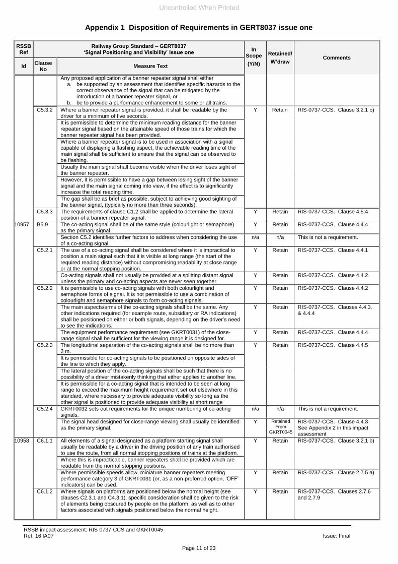
C5.3.2 Where a banner repeater signal is provided, it shall be readable by the driver for a minimum of five seconds.
Y Retain RIS-0737-CCS. Clause 3.2.1 b)
It is permissible to determine the minimum reading distance for the banner repeater signal based on the attainable speed of those trains for which the banner repeater signal has been provided.
Where a banner repeater signal is to be used in association with a signal capable of displaying a flashing aspect, the achievable reading time of the main signal shall be sufficient to ensure that the signal can be observed to be flashing.
Usually the main signal shall become visible when the driver loses sight of the banner repeater.
However, it is permissible to have a gap between losing sight of the banner signal and the main signal coming into view, if the effect is to significantly increase the total reading time.
The gap shall be as brief as possible, subject to achieving good sighting of the banner signal, (typically no more than three seconds).
C5.3.3 The requirements of clause C1.2 shall be applied to determine the lateral position of a banner repeater signal.
Y Retain RIS-0737-CCS. Clause 4.5.4
10957 B5.9 The co-acting signal shall be of the same style (colourlight or semaphore) as the primary signal.
Y Retain RIS-0737-CCS. Clause 4.4.4
Section C5.2 identifies further factors to address when considering the use of a co-acting signal.
n/a n/a This is not a requirement.
C5.2.1 The use of a co-acting signal shall be considered where it is impractical to position a main signal such that it is visible at long range (the start of the required reading distance) without compromising readability at close range or at the normal stopping position.
Y Retain RIS-0737-CCS. Clause 4.4.1
Co-acting signals shall not usually be provided at a splitting distant signal unless the primary and co-acting aspects are never seen together.
Y Retain RIS-0737-CCS. Clause 4.4.2
C5.2.2 It is permissible to use co-acting signals with both colourlight and semaphore forms of signal. It is not permissible to use a combination of colourlight and semaphore signals to form co-acting signals.
Y Retain RIS-0737-CCS. Clause 4.4.2
The main aspects/arms of the co-acting signals shall be the same. Any other indications required (for example route, subsidiary or RA indications) shall be positioned on either or both signals, depending on the driver’s need to see the indications.
Y Retain RIS-0737-CCS. Clauses 4.4.3. & 4.4.4
The equipment performance requirement (see GKRT0031) of the close-range signal shall be sufficient for the viewing range it is designed for.
Y Retain RIS-0737-CCS. Clause 4.4.4
C5.2.3 The longitudinal separation of the co-acting signals shall be no more than 2 m.
Y Retain RIS-0737-CCS. Clause 4.4.5
It is permissible for co-acting signals to be positioned on opposite sides of the line to which they apply.
The lateral position of the co-acting signals shall be such that there is no possibility of a driver mistakenly thinking that either applies to another line.
It is permissible for a co-acting signal that is intended to be seen at long range to exceed the maximum height requirement set out elsewhere in this standard, where necessary to provide adequate visibility so long as the other signal is positioned to provide adequate visibility at short range
C5.2.4 GKRT0032 sets out requirements for the unique numbering of co-acting signals.
n/a n/a This is not a requirement.
The signal head designed for close-range viewing shall usually be identified as the primary signal.
Y Retained From
GKRT0045
RIS-0737-CCS. Clause 4.4.3 See Appendix 2 in this impact assessment
10958 C6.1.1 All elements of a signal designated as a platform starting signal shall usually be readable by a driver in the driving position of any train authorised to use the route, from all normal stopping positions of trains at the platform.
Y Retain RIS-0737-CCS. Clause 3.2.1 b)
Where this is impracticable, banner repeaters shall be provided which are readable from the normal stopping positions.
Where permissible speeds allow, miniature banner repeaters meeting performance category 3 of GKRT0031 (or, as a non-preferred option, ‘OFF’ indicators) can be used.
Y Retain RIS-0737-CCS. Clause 2.7.5 a)
C6.1.2 Where signals on platforms are positioned below the normal height (see clauses C2.3.1 and C4.3.1), specific consideration shall be given to the risk of elements being obscured by people on the platform, as well as to other factors associated with signals positioned below the normal height.
Y Retain RIS-0737-CCS. Clauses 2.7.6 and 2.7.9
Uncontrolled When Printed
Appendix 1 Disposition of Requirements in GERT8037 issue one
RSSB impact assessment: RIS-0737-CCS and GKRT0045 Ref: 16 IA07 Issue: Final
Page 12 of 23
RSSB Ref
Railway Group Standard – GERT8037 ‘Signal Positioning and Visibility’ Issue one
In Scope
(Y/N)
Retained/
W’draw Comments
Id Clause
No Measure Text
It is permissible for miniature banner repeater signals to be positioned to the right of the line to which they apply if the platform is on the right-hand side and they are readable from the associated stopping position(s).
Y Retain RIS-0737-CCS. Clauses 2.7.5 and 2.7.9 and Appx C, C3
10959 C6.2.1 Switches or plungers required for train ready to start (TRTS), right away (RA) or close doors (CD) functions on a platform shall be co-located and shall be positioned where staff carrying out train dispatch duties can adequately observe the train they are dispatching.
Y Retain RIS-0737-CCS. Clause 2.7.5
Where platforms are bi-directional or have mid-platform signals, the layout and labelling of the switch/plunger units shall be such as to minimise the risk of operation of the wrong switch/plunger.
It is permissible for duplicate switch/plunger units to be provided where more than one dispatch position is required.
C6.2.2 ‘OFF’ indicators shall be provided in situations where the guard or person in charge of the platform is unable to see the platform starter signal or banner repeater signal from all designated dispatch positions.
Y Retain RIS-0737-CCS. Clause 3.2.1 b)
They shall be positioned so as to be readable by the dispatch staff from the dispatch position(s). GORT3475 sets out requirements for assessing methods of dispatch.
A banner repeater signal is not a suitable substitute for an ‘OFF’ indicator if it is replaced to danger by occupation of the signal berth track circuit.
n/a n/a This is not a requirement.
Where ‘OFF’ indicators are provided on bi-directional platforms or platforms equipped with mid-platform signals, the OFF indicator shall additionally indicate the signal or direction of movement to which it applies.
Y Retain RIS-0737-CCS. Clause 2.7.5 biii)
C6.2.3 CD and RA indicators, where required, shall meet all of the following requirements:
a be co-located with any platform starting signal provided and with any banner repeater signals (see clause C6.1.1).
b be positioned such that they are readable by the driver when stationary at any normal stopping position.
c. be positioned such that they are readable by the person in charge of the platform.
Where necessary, duplicate indicators shall be provided to achieve the requirements of this clause.
Y Retain RIS-0737-CCS. Clause 3.2.1 b)
10960 C6.4 No car stop marker or DOO monitor unit shall be positioned such that a train is required to stop within 25 m of the platform starting signal, except as permitted below:
It is permissible for the normal stopping position of a train to be within 25 m of the platform starting signal where the signal is sufficiently conspicuous such that a driver in the driving position is aware of the aspect displayed while looking at the route ahead.
Where there is doubt as to whether this is achievable, consideration shall be given to the use of additional control measures to reduce the likelihood or consequence of a SPAD. Such measures include, but are not limited to:
a. use of RA indicators as part of the train dispatch process b. a train protection system to stop trains short of any area of conflict
(as set out in GIRT7006). c. a suitably positioned co-acting signal.
Y Retain RIS-0737-CCS. Clauses 3.2.1b) , 2.7.6 & 2.7.7
10961 C7.1 The colours usually applied to signal structures and fittings are set out in GKRT0031.
n/a n/a This is not a requirement.
It is permissible to paint signal structures in a distinctive colour to aid drivers in locating a signal, and the line to which it applies, in a complex area.
Permitted arrangements are a. black for the horizontal part of a gantry or cantilever, where this will
distinguish it from other structures that are coloured grey (for example, OLE)
b. white and black hoops for a post.
Y Retain RIS-0737-CCS. Clauses 2.7.6, 2.7.9 and Appx C, C2
Overuse of such a measure can render it ineffective. n/a n/a This is not a requirement.
C7.2 It is permissible to provide countdown markers, as set out in GIRT7033, on the approach to signals where this is felt to be beneficial
Y Retain RIS-0737-CCS. Clause 3.2.1 b) Table 1
Such markers shall be provided as a sequence of three signs, positioned nominally 100 m apart with the last one nominally 100 m before the signal.
Other arrangements are permissible where it is considered that this will be of greater benefit to the driver.
n/a n/a This is not a requirement.
The use of countdown markers shall usually be determined as part of the risk assessment process required by GIRT7006.
Overuse of countdown markers can render them ineffective.
Uncontrolled When Printed
Appendix 1 Disposition of Requirements in GERT8037 issue one
RSSB impact assessment: RIS-0737-CCS and GKRT0045 Ref: 16 IA07 Issue: Final
Page 13 of 23
RSSB Ref
Railway Group Standard – GERT8037 ‘Signal Positioning and Visibility’ Issue one
In Scope
(Y/N)
Retained/
W’draw Comments
Id Clause
No Measure Text
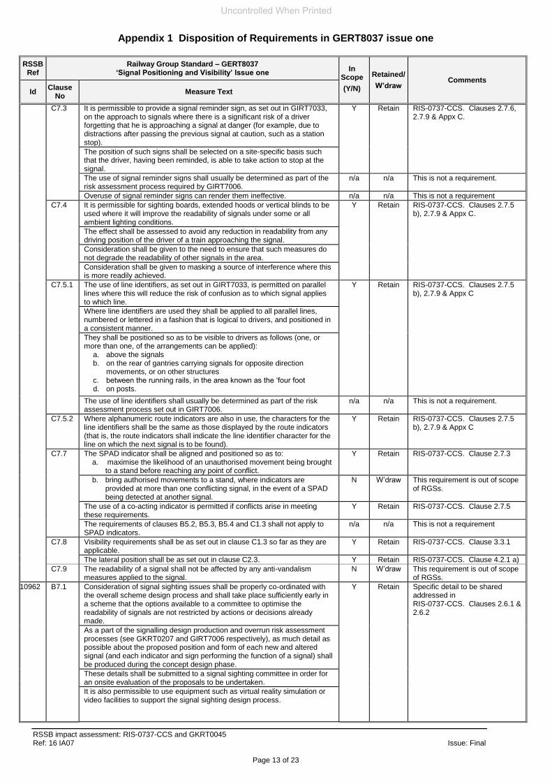
C7.3 It is permissible to provide a signal reminder sign, as set out in GIRT7033, on the approach to signals where there is a significant risk of a driver forgetting that he is approaching a signal at danger (for example, due to distractions after passing the previous signal at caution, such as a station stop).
Y Retain RIS-0737-CCS. Clauses 2.7.6, 2.7.9 & Appx C.
The position of such signs shall be selected on a site-specific basis such that the driver, having been reminded, is able to take action to stop at the signal.
The use of signal reminder signs shall usually be determined as part of the risk assessment process required by GIRT7006.
n/a n/a This is not a requirement.
Overuse of signal reminder signs can render them ineffective. n/a n/a This is not a requirement
C7.4 It is permissible for sighting boards, extended hoods or vertical blinds to be used where it will improve the readability of signals under some or all ambient lighting conditions.
Y Retain RIS-0737-CCS. Clauses 2.7.5 b), 2.7.9 & Appx C.
The effect shall be assessed to avoid any reduction in readability from any driving position of the driver of a train approaching the signal.
Consideration shall be given to the need to ensure that such measures do not degrade the readability of other signals in the area.
Consideration shall be given to masking a source of interference where this is more readily achieved.
C7.5.1 The use of line identifiers, as set out in GIRT7033, is permitted on parallel lines where this will reduce the risk of confusion as to which signal applies to which line.
Y Retain RIS-0737-CCS. Clauses 2.7.5 b), 2.7.9 & Appx C
Where line identifiers are used they shall be applied to all parallel lines, numbered or lettered in a fashion that is logical to drivers, and positioned in a consistent manner.
They shall be positioned so as to be visible to drivers as follows (one, or more than one, of the arrangements can be applied):
a. above the signals b. on the rear of gantries carrying signals for opposite direction
movements, or on other structures c. between the running rails, in the area known as the ‘four foot d. on posts.
The use of line identifiers shall usually be determined as part of the risk assessment process set out in GIRT7006.
n/a n/a This is not a requirement.
C7.5.2 Where alphanumeric route indicators are also in use, the characters for the line identifiers shall be the same as those displayed by the route indicators (that is, the route indicators shall indicate the line identifier character for the line on which the next signal is to be found).
Y Retain RIS-0737-CCS. Clauses 2.7.5 b), 2.7.9 & Appx C
C7.7 The SPAD indicator shall be aligned and positioned so as to: a. maximise the likelihood of an unauthorised movement being brought
to a stand before reaching any point of conflict.
Y Retain RIS-0737-CCS. Clause 2.7.3
b. bring authorised movements to a stand, where indicators are provided at more than one conflicting signal, in the event of a SPAD being detected at another signal.
N W’draw This requirement is out of scope of RGSs.
The use of a co-acting indicator is permitted if conflicts arise in meeting these requirements.
Y Retain RIS-0737-CCS. Clause 2.7.5
The requirements of clauses B5.2, B5.3, B5.4 and C1.3 shall not apply to SPAD indicators.
n/a n/a This is not a requirement
C7.8 Visibility requirements shall be as set out in clause C1.3 so far as they are applicable.
Y Retain RIS-0737-CCS. Clause 3.3.1
The lateral position shall be as set out in clause C2.3. Y Retain RIS-0737-CCS. Clause 4.2.1 a)
C7.9 The readability of a signal shall not be affected by any anti-vandalism measures applied to the signal.
N W’draw This requirement is out of scope of RGSs.
10962 B7.1 Consideration of signal sighting issues shall be properly co-ordinated with the overall scheme design process and shall take place sufficiently early in a scheme that the options available to a committee to optimise the readability of signals are not restricted by actions or decisions already made.
Y Retain Specific detail to be shared addressed in RIS-0737-CCS. Clauses 2.6.1 & 2.6.2
As a part of the signalling design production and overrun risk assessment processes (see GKRT0207 and GIRT7006 respectively), as much detail as possible about the proposed position and form of each new and altered signal (and each indicator and sign performing the function of a signal) shall be produced during the concept design phase.
These details shall be submitted to a signal sighting committee in order for an onsite evaluation of the proposals to be undertaken.
It is also permissible to use equipment such as virtual reality simulation or video facilities to support the signal sighting design process.
Uncontrolled When Printed
Appendix 1 Disposition of Requirements in GERT8037 issue one
RSSB impact assessment: RIS-0737-CCS and GKRT0045 Ref: 16 IA07 Issue: Final
Page 14 of 23
RSSB Ref
Railway Group Standard – GERT8037 ‘Signal Positioning and Visibility’ Issue one
In Scope
(Y/N)
Retained/
W’draw Comments
Id Clause
No Measure Text
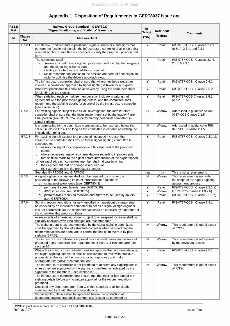
B7.2.1 For all new, modified and re-positioned signals, indicators, and signs that perform the function of signals, the infrastructure controller shall ensure that a signal sighting committee is convened to verify the proposed position and form.
Y Retain RIS-0737-CCS. Clauses 2.2.1 a) & b), 2.3.1, and 2.8.1
The committee shall: a. review any preliminary sighting proposals produced by the designers
and the signalling scheme plan b. identify any alterations or additions required c. Make recommendations as to the position and form of each signal in
order to optimise the driver’s approach view.
Y Retain RIS-0737-CCS. Clauses 2.7.5, 2.8.1 & 2.9.1
The infrastructure controller shall ensure that where multiple signals are involved, a consistent approach to signal sighting is taken for all signals.
Y Retain RIS-0737-CCS. Clause 2.6.2
Wherever practicable this shall be achieved by using the same personnel for sighting all the signals.
Y Retain RIS-0737-CCS. Clause 2.6.2
When satisfied, each committee member shall indicate in writing their agreement with the proposed sighting details, and the committee shall recommend the sighting details for approval by the infrastructure controller (see clause B7.6).
Y Retain RIS-0737-CCS Clauses 2.8.1, and 2.9.1 b)
B7.2.2 For existing signals subject to a SPAD investigation, the infrastructure controller shall ensure that the investigation remit set by the Inquiry Panel Chairperson (see GORT3252) is performed by personnel competent in signal sighting.
N W’draw Addressed in guidance to RIS-0737-CCS Clause 2.1.5
It is permissible for the committee membership to be restricted below that set out in clause B7.4.1 so long as the committee is capable of fulfilling the investigation remit set.
N W’draw Addressed in guidance to RIS-0737-CCS Clause 2.1.5
B7.2.3 For existing signals subject to a proposed linespeed increase, the infrastructure controller shall ensure that a signal sighting committee is convened to: a. assess the signal for compliance with this standard at the proposed
speed b. where necessary, make recommendations regarding improvements
that shall be made to the signal before introduction of the higher speed When satisfied, each committee member shall indicate in writing: c. their agreement that no change is required, or d. their agreement with the proposed changes
Y Retain RIS-0737-CCS. Clause 2.2.1 c).
See also GKRT0007 and GIRT7006 n/a n/a This is not a requirement.
B7.3 A signal sighting committee shall also be required to consider the positioning of the following items of infrastructure equipment:
a. signal post telephones (see GERT8048)
N W’draw This requirement is not within the scope of the signal sighting assessment process.
b. permanent speed boards (see GKRT0038) Y Retain RIS-0737-CCS. Clause 2.2.1 a)
c. AWS inductors (see GERT8035) Y W’draw GERT8075 Clause 2.1.8.2 h).
d. platform/track mounted monitors and mirrors to be used by drivers (see GERT8060)
Y Retain RIS-0737-CCS. Clause 2.2.1 a)
B7.6 Sighting recommendations for new, modified or repositioned signals shall be checked by an individual competent to act as a signal design engineer
Y Retain RIS-0737-CCS. Clause 2.8.1
It is not permissible for the recommendations to be checked by a member of the committee that produced them.
Assessments of an existing signal, subject to a linespeed increase shall be similarly checked even if no changes are recommended
The sighting details, as recommended by the signal sighting committee, shall be approved by the infrastructure controller when satisfied that the recommendations are adequate to control the risk of an overrun by poor sighting (SPAD).
N W’draw This requirement is out of scope of RGSs.
The infrastructure controller’s approval process shall review and assess all proposed departures from the requirements of Part C of this standard (see section B6).
N W’draw This requirement is addressed by the deviation process
Where the infrastructure controller does not approve the recommendations, the signal sighting committee shall be reconvened to review its previous proposals, in the light of the reasons for non-approval, and make appropriate alternative recommendations.
Y Retain RIS-0737-CCS. Clause 2.8.1
The infrastructure controller is not permitted to approve any sighting details unless they are supported by the sighting committee (as indicated by the signature of the members – see section B7.2).
N W’draw This requirement is out of scope of RGSs.
The infrastructure controller shall ensure that the checker has signed the sighting details before giving written approval for the recommendations produced.
Details of any departures from Part C of this standard shall be clearly identified and kept with the recommendations.
Signal sighting details shall be approved before the production of dependent engineering details commences (except as permitted by
Uncontrolled When Printed
Appendix 1 Disposition of Requirements in GERT8037 issue one
RSSB impact assessment: RIS-0737-CCS and GKRT0045 Ref: 16 IA07 Issue: Final
Page 15 of 23
RSSB Ref
Railway Group Standard – GERT8037 ‘Signal Positioning and Visibility’ Issue one
In Scope
(Y/N)
Retained/
W’draw Comments
Id Clause
No Measure Text
GKRT0207).
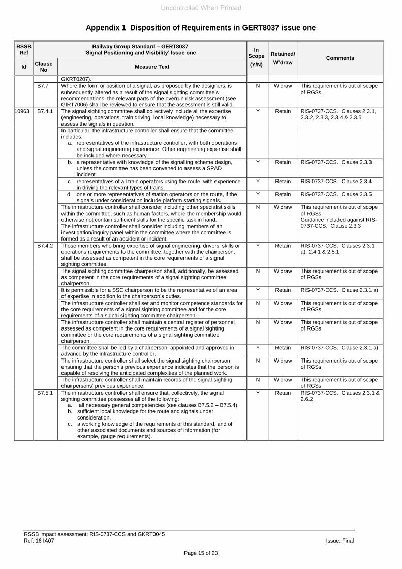
B7.7 Where the form or position of a signal, as proposed by the designers, is subsequently altered as a result of the signal sighting committee’s recommendations, the relevant parts of the overrun risk assessment (see GIRT7006) shall be reviewed to ensure that the assessment is still valid.
N W’draw This requirement is out of scope of RGSs.
10963 B7.4.1 The signal sighting committee shall collectively include all the expertise (engineering, operations, train driving, local knowledge) necessary to assess the signals in question.
Y Retain RIS-0737-CCS. Clauses 2.3.1, 2.3.2, 2.3.3, 2.3.4 & 2.3.5
In particular, the infrastructure controller shall ensure that the committee includes:
a. representatives of the infrastructure controller, with both operations and signal engineering experience. Other engineering expertise shall be included where necessary.
b. a representative with knowledge of the signalling scheme design, unless the committee has been convened to assess a SPAD incident.
Y Retain RIS-0737-CCS. Clause 2.3.3
c. representatives of all train operators using the route, with experience in driving the relevant types of trains.
Y Retain RIS-0737-CCS. Clause 2.3.4
d. one or more representatives of station operators on the route, if the signals under consideration include platform starting signals.
Y Retain RIS-0737-CCS. Clause 2.3.5
The infrastructure controller shall consider including other specialist skills within the committee, such as human factors, where the membership would otherwise not contain sufficient skills for the specific task in hand.
N W’draw This requirement is out of scope of RGSs. Guidance included against RIS-0737-CCS. Clause 2.3.3 The infrastructure controller shall consider including members of an
investigation/inquiry panel within the committee where the committee is formed as a result of an accident or incident.
B7.4.2 Those members who bring expertise of signal engineering, drivers’ skills or operations requirements to the committee, together with the chairperson, shall be assessed as competent in the core requirements of a signal sighting committee.
Y Retain RIS-0737-CCS. Clauses 2.3.1 a), 2.4.1 & 2.5.1
The signal sighting committee chairperson shall, additionally, be assessed as competent in the core requirements of a signal sighting committee chairperson.
N W’draw This requirement is out of scope of RGSs.
It is permissible for a SSC chairperson to be the representative of an area of expertise in addition to the chairperson’s duties.
Y Retain RIS-0737-CCS. Clause 2.3.1 a)
The infrastructure controller shall set and monitor competence standards for the core requirements of a signal sighting committee and for the core requirements of a signal sighting committee chairperson.
N W’draw This requirement is out of scope of RGSs.
The infrastructure controller shall maintain a central register of personnel assessed as competent in the core requirements of a signal sighting committee or the core requirements of a signal sighting committee chairperson.
N W’draw This requirement is out of scope of RGSs.
The committee shall be led by a chairperson, appointed and approved in advance by the infrastructure controller.
Y Retain RIS-0737-CCS. Clause 2.3.1 a)
The infrastructure controller shall select the signal sighting chairperson ensuring that the person’s previous experience indicates that the person is capable of resolving the anticipated complexities of the planned work.
N W’draw This requirement is out of scope of RGSs.
The infrastructure controller shall maintain records of the signal sighting chairpersons’ previous experience.
N W’draw This requirement is out of scope of RGSs.
B7.5.1 The infrastructure controller shall ensure that, collectively, the signal sighting committee possesses all of the following:
a. all necessary general competencies (see clauses B7.5.2 – B7.5.4). b. sufficient local knowledge for the route and signals under
consideration. c. a working knowledge of the requirements of this standard, and of
other associated documents and sources of information (for example, gauge requirements).
Y Retain RIS-0737-CCS. Clauses 2.3.1 & 2.6.2
Uncontrolled When Printed
Appendix 1 Disposition of Requirements in GERT8037 issue one
RSSB impact assessment: RIS-0737-CCS and GKRT0045 Ref: 16 IA07 Issue: Final
Page 16 of 23
RSSB Ref
Railway Group Standard – GERT8037 ‘Signal Positioning and Visibility’ Issue one
In Scope
(Y/N)
Retained/
W’draw Comments
Id Clause
No Measure Text
B7.5.2 The signal sighting committee shall be collectively competent to consider the effects of the following factors on the likelihood of an overrun occurring:
a. gradients and permissible/attainable speeds. b. aspect sequences and form of junction signalling, including those of
existing signals. c. routes by which a driver could approach a signal. d. grouping of parallel signals and the potential for drivers to be
confused as to which one applies to the line they are on. e. train working arrangements (including running and shunting
movements, and movements onto occupied lines). f. normal stopping positions of trains. g. train dispatch arrangements. h. complexity of infrastructure (for example, station areas, overhead line
equipment, curved approaches, bridges). i. types of trains authorised or planned to operate over the route and in
particular their cab sightlines (see also GM/RT2161). j. irregular or excessive spacings of signals k. potential driver distractions (for example, station stops, speed
restrictions, neutral sections) l. ambient lighting conditions (including effects of reflected or
background sunlight) m. effects of artificial lighting (reflected and background) n. reading through to other signals o. signals unusually positioned (for example, on right-hand side of line) p. position of AWS in relation to signal (see GERT8035) q. train radio coverage
N W’draw This requirement is out of scope of RGSs.
B7.5.3 The signal sighting committee shall be collectively competent to consider the following issues:
a. structure gauge, clearances and other matters related to the infrastructure and proposed signal structures, including any alterations to the infrastructure that are planned to take place.
b. the compatibility of signals and electric traction equipment, for example any conflicts between the positions of neutral sections and the positions of signals (see GKRT0032), and potential interruptions to signal visibility.
c. local problems or special conditions, for example a previous history of overruns in the vicinity; driver’s complaints regarding the approach view; areas of high vandalism; signs with the potential to obstruct signal visibility.
N W’draw This requirement is out of scope of RGSs.
B7.5.4 The signal sighting committee shall be collectively competent to make recommendations concerning:
a. form of new or modified signals b. longitudinal and lateral position of each signal. c. the reading time for each signal (including the acceptability of any
interruptions). d. alignment and close-up viewing requirements for each signal. e. measures for overrun risk control. f. train dispatch arrangements from platforms and associated train
dispatch equipment (see section C6). g. arrangements for maintainability of signals.
y Retain RIS-0737-CCS. Clause 2.3.2)
10964 B8.1 The requirements for the testing and commissioning of signals are set out in GKRT0209.
n/a n/a This is not a requirement.
The infrastructure controller shall ensure that the tests include: a. a compliance check of the installed signal against the approved
sighting details b. an adequacy check to ensure that the driver’s view is adequate to
reliably identify and observe the signal and correctly interpret the signalling information
N W’draw This requirement is out of scope of RGSs.
The adequacy check shall be carried out from the driving cab using rolling stock appropriate to the line of route or from the track using a periscope or equivalent device. If it is not reasonably practicable to observe every aspect combination from all possible approaches; a representative sample of all combinations shall be observed, selecting, where possible, for this sample, those giving the greatest potential for misreading or incorrect driver response. Where reasonably practicable, these checks shall be conducted before the signals are brought into service. Where this is not reasonably practicable, it is permissible for the checks to be carried out (or completed) within seven days after the signals are brought into service.
Uncontrolled When Printed
Appendix 1 Disposition of Requirements in GERT8037 issue one
RSSB impact assessment: RIS-0737-CCS and GKRT0045 Ref: 16 IA07 Issue: Final
Page 17 of 23
RSSB Ref
Railway Group Standard – GERT8037 ‘Signal Positioning and Visibility’ Issue one
In Scope
(Y/N)
Retained/
W’draw Comments
Id Clause
No Measure Text
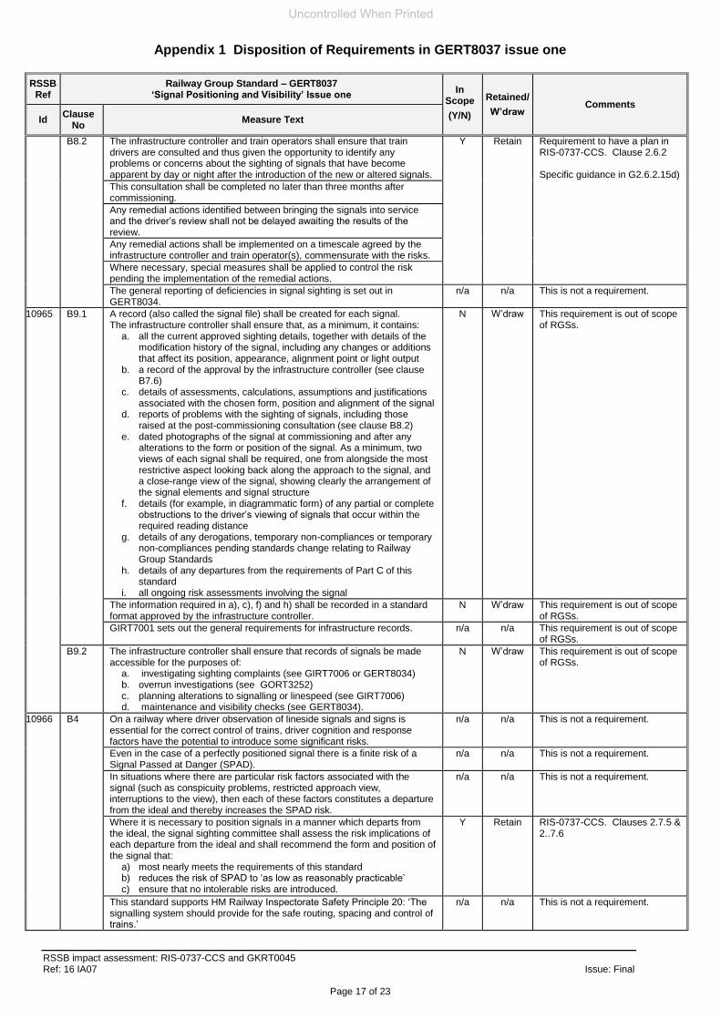
B8.2 The infrastructure controller and train operators shall ensure that train drivers are consulted and thus given the opportunity to identify any problems or concerns about the sighting of signals that have become apparent by day or night after the introduction of the new or altered signals.
Y Retain Requirement to have a plan in RIS-0737-CCS. Clause 2.6.2 Specific guidance in G2.6.2.15d)
This consultation shall be completed no later than three months after commissioning.
Any remedial actions identified between bringing the signals into service and the driver’s review shall not be delayed awaiting the results of the review.
Any remedial actions shall be implemented on a timescale agreed by the infrastructure controller and train operator(s), commensurate with the risks.
Where necessary, special measures shall be applied to control the risk pending the implementation of the remedial actions.
The general reporting of deficiencies in signal sighting is set out in GERT8034.
n/a n/a This is not a requirement.
10965 B9.1 A record (also called the signal file) shall be created for each signal. The infrastructure controller shall ensure that, as a minimum, it contains:
a. all the current approved sighting details, together with details of the modification history of the signal, including any changes or additions that affect its position, appearance, alignment point or light output
b. a record of the approval by the infrastructure controller (see clause B7.6)
c. details of assessments, calculations, assumptions and justifications associated with the chosen form, position and alignment of the signal
d. reports of problems with the sighting of signals, including those raised at the post-commissioning consultation (see clause B8.2)
e. dated photographs of the signal at commissioning and after any alterations to the form or position of the signal. As a minimum, two views of each signal shall be required, one from alongside the most restrictive aspect looking back along the approach to the signal, and a close-range view of the signal, showing clearly the arrangement of the signal elements and signal structure
f. details (for example, in diagrammatic form) of any partial or complete obstructions to the driver’s viewing of signals that occur within the required reading distance
g. details of any derogations, temporary non-compliances or temporary non-compliances pending standards change relating to Railway Group Standards
h. details of any departures from the requirements of Part C of this standard
i. all ongoing risk assessments involving the signal
N W’draw This requirement is out of scope of RGSs.
The information required in a), c), f) and h) shall be recorded in a standard format approved by the infrastructure controller.
N W’draw This requirement is out of scope of RGSs.
GIRT7001 sets out the general requirements for infrastructure records. n/a n/a This requirement is out of scope of RGSs.
B9.2 The infrastructure controller shall ensure that records of signals be made accessible for the purposes of:
a. investigating sighting complaints (see GIRT7006 or GERT8034) b. overrun investigations (see GORT3252) c. planning alterations to signalling or linespeed (see GIRT7006) d. maintenance and visibility checks (see GERT8034).
N W’draw This requirement is out of scope of RGSs.
10966 B4 On a railway where driver observation of lineside signals and signs is essential for the correct control of trains, driver cognition and response factors have the potential to introduce some significant risks.
n/a n/a This is not a requirement.
Even in the case of a perfectly positioned signal there is a finite risk of a Signal Passed at Danger (SPAD).
n/a n/a This is not a requirement.
In situations where there are particular risk factors associated with the signal (such as conspicuity problems, restricted approach view, interruptions to the view), then each of these factors constitutes a departure from the ideal and thereby increases the SPAD risk.
n/a n/a This is not a requirement.
Where it is necessary to position signals in a manner which departs from the ideal, the signal sighting committee shall assess the risk implications of each departure from the ideal and shall recommend the form and position of the signal that:
a) most nearly meets the requirements of this standard b) reduces the risk of SPAD to ‘as low as reasonably practicable’ c) ensure that no intolerable risks are introduced.
Y Retain RIS-0737-CCS. Clauses 2.7.5 & 2..7.6
This standard supports HM Railway Inspectorate Safety Principle 20: ‘The signalling system should provide for the safe routing, spacing and control of trains.’
n/a n/a This is not a requirement.
Uncontrolled When Printed
Appendix 1 Disposition of Requirements in GERT8037 issue one
RSSB impact assessment: RIS-0737-CCS and GKRT0045 Ref: 16 IA07 Issue: Final
Page 18 of 23
RSSB Ref
Railway Group Standard – GERT8037 ‘Signal Positioning and Visibility’ Issue one
In Scope
(Y/N)
Retained/
W’draw Comments
Id Clause
No Measure Text
12980 B5.1 Signals shall be positioned and aligned so as to ensure that: a) the driver of an approaching train has sufficient time to identify,
observe and interpret the information being displayed b) the information being presented is clear and unambiguous c) the risk of reading the wrong signal is minimised d) the presentation of information displayed to the driver is such as to
avoid information overload.
Y Retain RIS-0737-CCS. Clauses 2.7.3, 2.7.4 and 2.7.6
12981 B5.5 As far as is reasonably practicable, hazards (identified in the requirements set out in clause B5.2.2) and obstructions to the driver’s view of the signal shall be removed so as to maximise the reading distance achievable (known as the achievable reading distance) and minimise hazards that could increase the risk of driver error.
Y Retain RIS-0737-CCS. Clauses 2.7.6, 2.7.7., 2.7.8, 2.7.9 and 2.7.10.
Where alterations have been made that affect hazards identified, the assessed minimum reading time shall be reviewed.
12982 B6 The contents of Part C of this standard represent current best practice for the appearance, sighting and alignment of signals.
n/a n/a This is not a requirement.
Signals shall usually be positioned in accordance with Part C; however, it is permissible not to comply with all the details stated, but any departures from the requirements of Part C shall be permitted only if:
a) supported by all disciplines represented on the signal sighting committee.
b) approved by the infrastructure controller c) the details and justification of the departures from the requirements
of Part C are recorded in the signal file.
Y Retain RIS-0737-CCS Part 4.1 together with the deviation process
The infrastructure controller shall review all such departures to ensure that the rationale being applied is consistent, logical, justified and complies with the principal requirements identified in clause B5.1.
The application of this clause B6 does not absolve Railway Group members from seeking derogations, temporary non-compliances or non-compliances pending standards change from other relevant Railway Group Standards.
12983 B7.4.1 n/a n/a Duplicate of 10963
12984 B7.4.2 n/a n/a Duplicate of 10963
12985 C1.3.4 Consideration shall be given to the risk of a driver reading-through to a signal beyond that which should next be obeyed and which might reasonably be expected to be displaying a less restrictive aspect (typically beyond a junction or level crossing).
Y Retain RIS-0737-CCS. Clause 2.7.9
Where this risk is considered unacceptable, measures shall be introduced (such as reducing the conspicuity of the forward signal or applying special controls to the signal aspect) to mitigate the risk (see GKRT0060).
N Retain RIS-0737-CCS Appx C, C12
12986 C1.5 Lineside signs, required to be observed by a driver for the purpose of controlling the train, shall be positioned so as not to create unnecessary distraction from the driver’s primary role of observing signals.
Y Retain RIS-0737-CCS Appx C, C6
So far as is reasonably practicable, signs shall not be positioned between the signal and its associated AWS or within 50 m beyond the signal.
If the sign has AWS equipment associated with it, the sign shall be positioned such that the AWS for the sign does not fall between the signal and its AWS equipment.
Where this is not achievable, the sign shall be positioned at the signal and consideration shall be given to the size, lateral position and reflective properties, to ensure that all the information displayed is proportionate and that no part is so prominent as to make other parts appear insignificant.
GKRT0038 sets out requirements for positioning signs associated with permissible speeds. GERT8035 sets out requirements for the positioning of AWS track equipment.
n/a n/a This is not a requirement.
12987 C2.4 Consideration shall be given to the possible effect on the displayed aspect during a partial failure such as a filament failure.
N W’draw This requirement is out of scope of RGSs
Where this is considered to have a noticeable effect on the appearance, position or alignment of the lit aspect, an assessment shall be carried out to determine whether the consequent change is acceptable.
12988 C6.3 Monitors and mirrors for DOO shall be positioned: a) so as not to obscure the view of any signal for drivers of stopping or
non-stopping trains b) so as to minimise the risk of a SAS SPAD.
Y Retain RIS-0737-CCS. Clauses 2.7.6 & 3.2.1 b)
Technical requirements for DOO monitors and mirrors are set out in GERT8060.
n/a n/a This is not a requirement.
12989 C7.6 The use of an arrow sign fitted close to the signal head and pointing to the left or right to indicate to which track the signal applies, is permitted.
Y Retain RIS-0737-CCS. Clauses 2.7.5 b), 2.7.9 & Appx C.
Its use shall be limited to signals where a risk of confusion about which track it applies to has been identified and no other measures to reduce the risk are practicable.
Uncontrolled When Printed
Appendix 1 Disposition of Requirements in GERT8037 issue one
RSSB impact assessment: RIS-0737-CCS and GKRT0045 Ref: 16 IA07 Issue: Final
Page 19 of 23
RSSB Ref
Railway Group Standard – GERT8037 ‘Signal Positioning and Visibility’ Issue one
In Scope
(Y/N)
Retained/
W’draw Comments
Id Clause
No Measure Text
12990 C7.11 Where signalling equipment is to be provided that has not been identified in GKRT0031, it shall be:
a) positioned in accordance with clause B5.1 b) approved for the intended use by the infrastructure controller c) Positioned in accordance with any requirements specified by the
infrastructure controller.
Y Retain RIS-0737-CCS. Clause 2.7.5
B5.6 The form of approved signals are set out in GKRT0031. n/a n/a This is not a requirement.
C1.1.2 Consideration shall be given to the adequacy of train radio coverage when positioning signals.
N W’draw Addressed by GERT8270.
If necessary, the coverage shall be improved to suit the positioning of the signal.
N W’draw This requirement is out of scope of RGSs
Where the radio system automatically routes calls to the appropriate signaller, the radio system shall be checked to ensure that routing is applied correctly (see GERT8080).
N W’draw This requirement is out of scope of RGSs
C7.10 GIRT7033 sets out requirements associated with proposals to introduce new designs for signs.
n/a n/a This is not a requirement.
Uncontrolled When Printed
Appendix 2 Requirements transferred from GKRT0045 issue four to RIS-0737-CCS issue one
RSSB impact assessment: RIS-0737-CCS and GKRT0045 Ref: 16 IA07 Issue: Final
Page 20 of 23
RSSB Id
GKRT0045 Clause
Requirement RIS-0737-CCS Clause
15133 2.1.2 Signals and indicators shall be readable when viewed from the driving cab. 2.7.4
15068 2.2.1.1 Except where signal sighting can be consistently achieved without a backboard (for example, where a signal is positioned in a dark environment), a backboard shall be provided with each colour light signal.
2.7.5 b)
2.7.6 – 2.7.10
2.2.1.2 Where a separate backboard is provided behind the signal head, it shall be of sufficient size to appear no smaller than a signal head mounted backboard.
2.7.5 bii)
15089 2.2.10.1 Buffer stop lights, where provided, shall comply with all of the following:
a) Display signal red lights, except in sidings at locations where provision of red buffer stop lights would mislead drivers or affect the readability of signals on adjacent lines. In this case the buffer stop lights shall display white lights.
b) Be vertically aligned above the centre line of the track. c) Be configured so that the lower light is positioned 2400 mm (+/-100 mm) above rail level,
and the higher light is positioned to provide a separation distance of 150 mm (+/-10 mm) between the nearest edges of the two lights.
d) Be positioned at the buffer stop, in the same vertical plane as the buffer stop, except where the buffer stop is associated with a sand drag, in which case the lights shall be positioned at the entry end of the sand drag.
4.7.1 & 4.7.2
15069 2.2.2.1 The primary head and offset head shall:
a) Be mounted so that the horizontal separation between signal light centres in the two colour light signal heads is 600 mm – 900 mm, and
b) Be positioned and aligned so that horizontally displayed signal lights appear level to the train driver (see example in Figure 1).
4.2.4
2.2.2.2 The splitting distant signal shall be positioned so that the primary head is located as near as practicable to the driver’s line of sight, that is to say:
a) For signals mounted on the left-hand side of the line, the primary head shall be mounted to the right-hand side of the offset head (see example in Figure 1), and
b) For signals mounted on the right-hand side of the line, the primary head shall be mounted to the left-hand side of the offset head.
a) Primary signal and, where relevant, route indicator equipment that is positioned to provide the required long-distance signal sighting and readability, as set out in GERT8037, and
b) Co-acting signal and route indicator equipment that displays the same form (that is to say, colour light or semaphore) of signal aspect and route indication as the primary equipment, and positioned to provide the required close-up signal sighting and readability, as set out in GERT8037.
4.4.3 & 4.4.4
2.2.3.2 The primary and co-acting signal and route indicator equipment shall meet the same performance requirements, except where there is insufficient space to provide compatible equipment, in which case:
a) The primary signal and route indicator equipment shall meet the appropriate performance requirement compatible with the long-distance signal sighting and readability, and
b) The co-acting signal head and route indicator equipment shall meet the performance requirement that is appropriate for close-up signal sighting and readability.
2.7.5 a) and 2.7.7
2.2.3.3 The same main signal aspect and route indication shall be displayed by the primary and co-acting signals at all times.
4.4.4
2.2.3.4 The same subsidiary / shunting aspect and route indication shall be displayed by the primary and co-acting signals at all times, except at signals where subsidiary / shunting aspects and route indications are omitted from the primary signal.
4.4.4
2.2.3.5 Subsidiary / shunting signal aspects and route indications shall only be omitted from the primary signal if the co-acting signal equipment, on its own, provides the required sighting and readability for these aspects.
4.4.4
15072 2.2.4.2 Where independent position light signals are to be added to an existing signalling layout that includes independent position light signals that display a different form of ON aspect, the signalling layout shall be designed so that:
a) Drivers will not observe the different forms of ON aspect at the same time during train movements, and
b) The transition between the different forms of ON aspect is clearly defined.
4.2.8
18206 2.2.5.1 Position light junction indicators shall be positioned either above or to one side of the associated colour light signal head to provide the required signal sighting and readability of the combined signal aspects and route indications.
4.2.6 a)
2.2.5.2 The separation distance between an illuminated signal light and the nearest lunar white light or bar of light point shall be 550 mm (minimum) and 1230 mm (maximum).
4.2.6 a)
15086 2.2.8.1 Where a TPWS indicator is required at a stop board, it shall be positioned either:
a) Underneath the relevant stop board so that it is readable from the driving cab, or b) Remotely from the stop board; only where drivers are required to leave the driving cab to
operate signalling equipment (for example, associated with driver operated token exchange equipment).
4.6.1
2.2.8.2 Where a TPWS indicator at a stop board is combined with a points indicator (for example, at the exit of a passing loop on a single line operated using the no-signaller token remote block system), the points indicator shall be positioned next to the TPWS indicator, so that the points indication is closest to the driver’s line of sight.
4.6.2
Uncontrolled When Printed
Appendix 2 Requirements transferred from GKRT0045 issue four to RIS-0737-CCS issue one
RSSB impact assessment: RIS-0737-CCS and GKRT0045 Ref: 16 IA07 Issue: Final
Page 21 of 23
RSSB Id
GKRT0045 Clause
Requirement RIS-0737-CCS Clause
2.2.8.3 Where a TPWS indicator at a stop board is associated with a points indicator and a driver’s level crossing indicator:
a) The points indicator shall be positioned next to the TPWS indicator, so that the points indication is closest to the driver’s line of sight, and
b) The driver’s level crossing indicator shall be positioned adjacent to the stop board separately from the points / TPWS indication so that concurrently displayed indications are both readable as separate indications.
4.6.2
2.2.8.4 Where a TPWS indication is associated with a points indicator and / or a level crossing indicator, the indications shall be consistently displayed in a logical sequence at each location along a line of route.
2.7.5 a), 2.7.7 and 2.7.9.
2.2.10.1 Buffer stop lights, where provided, shall comply with all of the following:
a) Display signal red lights, except in sidings at locations where provision of red buffer stop lights would mislead drivers or affect the readability of signals on adjacent lines. In this case the buffer stop lights shall display white lights.
b) Be vertically aligned above the centre line of the track. c) Be configured so that the lower light is positioned 2400 mm (+/-100 mm) above rail level,
and the higher light is positioned to provide a separation distance of 150 mm (+/-10 mm) between the nearest edges of the two lights.
d) Be positioned at the buffer stop, in the same vertical plane as the buffer stop, except where the buffer stop is associated with a sand drag, in which case the lights shall be positioned at the entry end of the sand drag.
4.7.1 & 4.7.2
15095 3.1.4.2 A points indicator that displays only a yellow light or a steady red light / yellow light shall only be provided on lines where it is necessary to display consistent indications along a line of route already fitted with this form of indication.
2.7.5 a), 2.7.7 and 2.7.9.
15095 3.1.5.5 The number, position and alignment of loading / unloading indicators shall provide for unobstructed sighting and readability of at least one indicator at all times under conditions of clear visibility.
3.2.1 b)
15098 4.1.3.5 Signal heads that do not display a double yellow aspect as part of a non-standard 4-aspect sequence shall retain the same signal head format as the 4-aspect signals in the sequence
4.2.2
15100 4.1.5.1 Signals that display the first caution aspect in the 3-aspect sequence shall not have the appearance of a 4-aspect signal, except where the transition occurs at a 4-aspect junction signal where only the diverging route(s) incorporates the 4-aspect to 3-aspect transition.
4.2.3
15109 4.2.1.1 Splitting banner repeating signals shall only be provided where:
a) A banner repeating signal is required on the approach to a junction signal, and b) It is necessary to distinguish between an OFF banner aspect for different routes at the
diverging junction.
4.5.2
15071 4.2.1.4 The dimension between the centre of the two signal heads of a splitting banner repeating signal shall be:
a) 1000 mm (+/- 100 mm) in the horizontal plane, and b) 500 mm (+/- 50 mm) in the vertical plane, except where there is no obvious straight ahead
route at the junction, in which case the two signal heads shall be positioned at the same level.
4.5.5
15112 5.1.3.1 The position of junction signals shall, if practicable, be such that the driver of an approaching train can read the route indicator at the same time as the associated OFF aspects.
2.7.3
15121 5.2.6.4 When a signal aspect sequence is displayed that does not extend beyond the associated junction signal, the relevant OFF signal aspect shall only be displayed by the primary head.
4.2.1 a)
5.2.6.5 Where a splitting distant signal is also a junction signal, the relevant route indication shall be displayed in association with the primary head.
Uncontrolled When Printed
Appendix 3 New requirements.in RIS-0737-CCS issue one
RSSB impact assessment: RIS-0737-CCS and GKRT0045 Ref: 16 IA07 Issue: Final
Page 22 of 23
RIS-0737-CCS Clause
Requirement
2.4.2 RUs shall share SSC representation only if the nominated person(s) has sufficient understanding to fulfil the role requirements.
2.5.2 IM (stations) shall share an SSC member only if the nominated person has sufficient understanding to fulfil the role requirements
2.6.2 The signal sighting assessment plan shall record the following information relevant to the assessment:
a) Why the assessment is needed. b) What will be assessed. c) When the assessment will take place. d) Where the assessment will take place. e) Who will perform the assessment. f) Which assessment method will be used. g) How the assessment will be done.
h) The assumptions, dependencies and caveats underpinning the assessment.
2.7.2 The SSC shall perform the signal sighting assessment using a sufficiently accurate representation of the real operational context or in the real operational context.
2.9.1 The following signal sighting assessment records shall be retained for the life of the asset:
a) The signal sighting assessment plan. b) The SSC membership. c) The assessment result. d) The SSC decisions supporting the assessment result, including:
i) The MRT(s). ii) The MRD(s). iii) The RRD(s). iv) The asset configuration.
e) The reasons underpinning the assessment decisions including: i) The applicability of visible distance performance to interpretability, where this option has been
used. ii) The applicability of the compatibility factors to the asset being assessed. iii) The method(s) of eliminating or militating against each applicable factor.
f) Any further assumptions, dependencies and caveats, including recommendations about any compatibility factors that are relevant to signal sighting but which are not eliminated and require further risk assessment.
3.2.4 Where it is proposed to use visible distance performance of an asset to achieve the MRD, the SSC shall: a) Confirm that visibility alone is sufficient to support interpretability of the presented display or display
combination, and b) Determine the maximum distance from the asset at which the relevant display(s) is readable.
4.3.3 Where an alphanumeric route indicator is provided at a semaphore main stop signal, the SSC shall determine the relative position of the signal and indicator equipment and the value of dimensions ‘a’ and ‘b’ shown in figure 7.
b
Signal post
22
a
Figure 7 Example of an alphanumeric route indicator at a semaphore signal
4.3.4 Where an alphanumeric route indicator is provided with a shunting disc signal, the SSC shall determine the relative position of the signal and indicator equipment and value of dimensions ‘a’ and ‘b’ shown in figure 8.
b
2
a
2 2
a
Figure 8 Example of an alphanumeric route indicator at a shunting disc sig
4.5.3 The SSC shall confirm the type of banner repeater indicator to be provided, either:
a) 2-state banner repeater indicator. b) 3-state banner repeater indicator.
4.2.6 b Where a colour light signal is configured with a junction indicator, the SSC shall:
b) Determine whether a blue pivot light is necessary to improve the readability of the junction indication
4.7.2 The vertical position of the buffer stop lights shall comply with Figure 10.
Uncontrolled When Printed
Appendix 3 New requirements.in RIS-0737-CCS issue one
RSSB impact assessment: RIS-0737-CCS and GKRT0045 Ref: 16 IA07 Issue: Final