Bringing Science to Life Impact Modeling of Random Carbon Fiber Composites PI: Srdan Simunovic Haeng-Ki Lee, J. Michael Starbuck, Pakal Rahulkumar, Raymond G. Boeman Oak Ridge National Laboratory http://www-explorer.ornl.gov/composites
Transcript
Bringing Science to Life
Impact Modeling of Random Carbon FiberComposites
PI: Srdan SimunovicHaeng-Ki Lee, J. Michael Starbuck,
Pakal Rahulkumar, Raymond G. Boeman
Oak Ridge National Laboratoryhttp://www-explorer.ornl.gov/composites
Bringing Science to Life
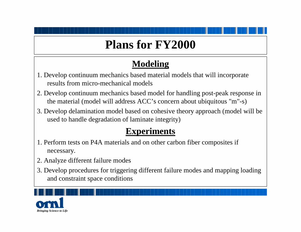
Summary for FY1999Modeling
1. Developed a number of material models based on micro-mechanics that includefiber debonding, matrix micro-cracking and fiber failure.
2. Implemented material models into Dyna3d and performed simulations forsimple geometries
3. Documented developments in journal papers, conference proceedings andtechnical report
Experiments1. Developed new fixture design for characterization of controlled crash failure of composite materials2. Tested several composite materials materials for fixture evaluation and
development3. Documented developments in project reports and conference proceedings
Bringing Science to Life
ModelingConstitutive Modeling for Impact
Simulation of Random Fiber Composites
Haeng-Ki Lee, Pakal Rahulkumar,Srdan Simunovic
Bringing Science to Life
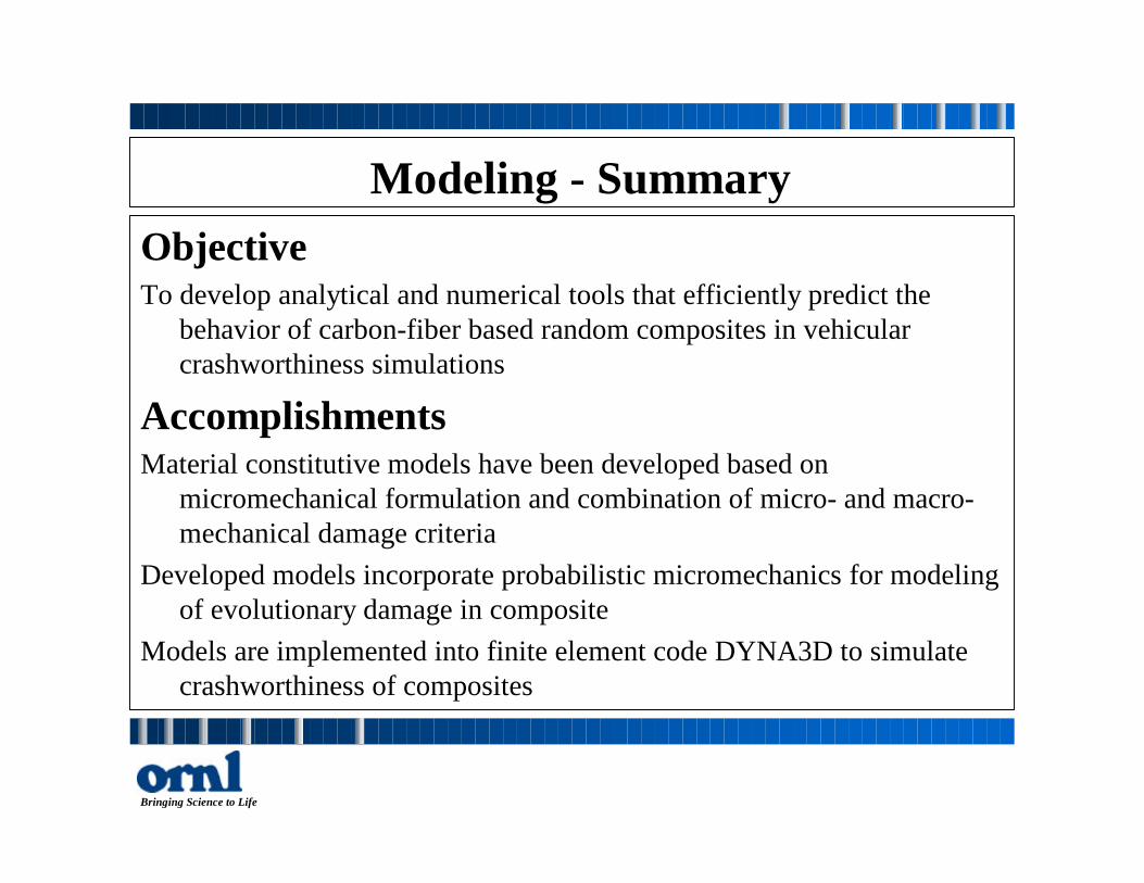
Modeling - SummaryObjectiveTo develop analytical and numerical tools that efficiently predict the
behavior of carbon-fiber based random composites in vehicularcrashworthiness simulations
AccomplishmentsMaterial constitutive models have been developed based on
micromechanical formulation and combination of micro- and macro-mechanical damage criteria
Developed models incorporate probabilistic micromechanics for modelingof evolutionary damage in composite
Models are implemented into finite element code DYNA3D to simulatecrashworthiness of composites
Bringing Science to Life
Micromechanics and Equivalence Principle
Heterogeneouscomposite
Equivalenthomogeneous
material
σo or εo σo or εo
I IIFiber
Matrix
Micromechanics based modeling
Heterogeneous composite is replaced by equivalenthomogeneous material using equivalent principlesbased on homogenization
Bringing Science to Life
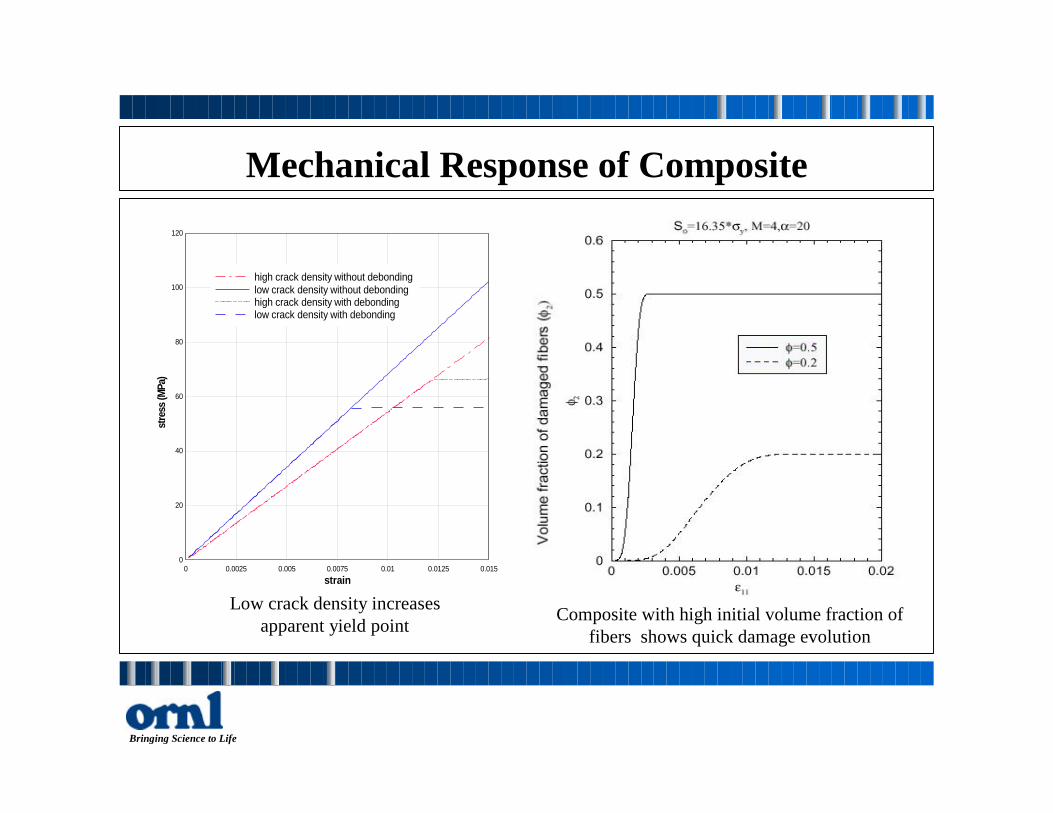
Mechanical Response of Composite
Low crack density increasesapparent yield point
strain
stre
ss (M
Pa)
0 0.0025 0.005 0.0075 0.01 0.0125 0.0150
20
40
60
80
100
120
high crack density without debondinglow crack density without debondinghigh crack density with debondinglow crack density with debonding
Composite with high initial volume fraction offibers shows quick damage evolution
Bringing Science to Life
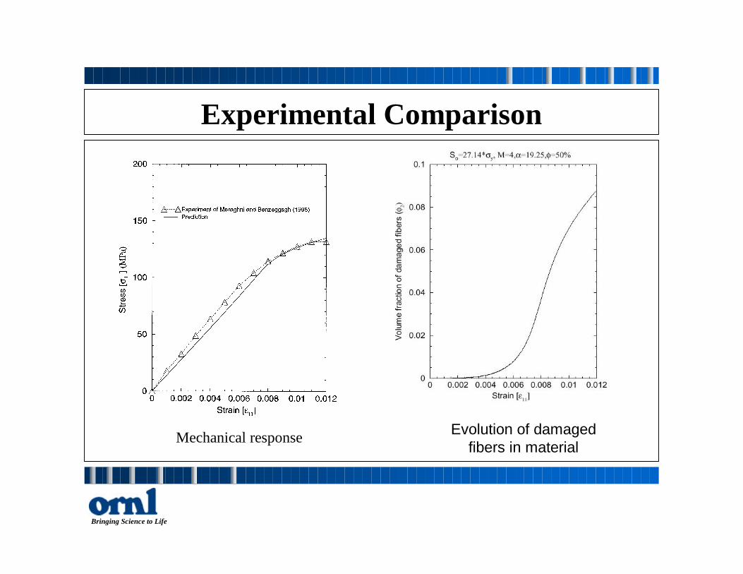
Experimental Comparison
Mechanical response Evolution of damagedfibers in material
Bringing Science to Life
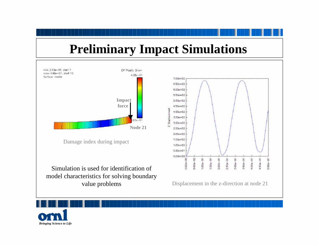
Preliminary Impact Simulations
Simulation is used for identification ofmodel characteristics for solving boundary
value problems
Impact force
Node 21
Damage index during impact
Displacement in the z-direction at node 21
Bringing Science to Life
Initial Tube Impact Simulations
Simulation is used for analysis of material modelfeatures in tube crush test. The model does notincorporate material failure (FY2000 task)
Effective stress during impact Damage index during impact
Bringing Science to Life
Modeling of Delamination in Composites
•Many possible fracturemechanisms across interfaces
– van der Waals forces– Adhesion bond breaking– void formation and
coalescence•Fracture mechanisms could be
rate-independent or rate-dependent σ
Mathematical ModelCohesive Zone
σActual MaterialCohesive Zone
Bringing Science to Life
Cohesive Zone Modeling of Delamination
• Cohesive zone models implemented as cohesiveelements are used simulate various fracture mechanisms
• Cohesive zone tractions account for the energydissipation during crack formation and propagationduring delamination failures
• Composite bulk material behavior modeled by regularfinite elements and can be elastic, elastic-plastic,viscoelastic, etc.
• Easy to handle automatic delamination nucleation, crackpath selection, and multiple failure locations
Bringing Science to Life
Delamination - Technical Issues• Separation of composite bulk and interfacial contributions to measured
global fracture energy• Effect of bulk material behavior, i.e. viscoelasticity, plasticity, and
composite ply orientations on measured global fracture energies• Insights into 3-D effects at free edges/corners that cause failure
initiation• Mechanical performance issues - first cracking strength, stiffness
degradation, post-failure strength, impact energy, under quasi-static anddynamic conditions
• Structural scaling effects of geometry on accompanying energyabsorption and failure modes
Bringing Science to Life
Example: Compressive Shear Test of Automotive WindshieldExperiments - Simulation
•Successful in modelingthe stable and unstableregimes of crackgrowth
Bringing Science to Life
Delamination Modeling - Summary•Family of cohesive elements will be used to model
degradation of ply-wise material structural integrity•Separates constitutive description of fracture and bulk
material properties•Suitable for various materials and solution procedures•Promising for use in multiple failure situations•Need to validate cohesive zone modeling approach by
comparison with experiments from quasi-static and dynamicfailure tests
•Refine and develop cohesive zone models for fracturemechanisms accompanying failures in composites
Bringing Science to Life
ExperimentsEnergy Absorbing Mechanisms in Composite
Strips under Progressive Crushing
J. Michael Starbuck, Raymond G. BoemanSrdan Simunovic
Bringing Science to Life
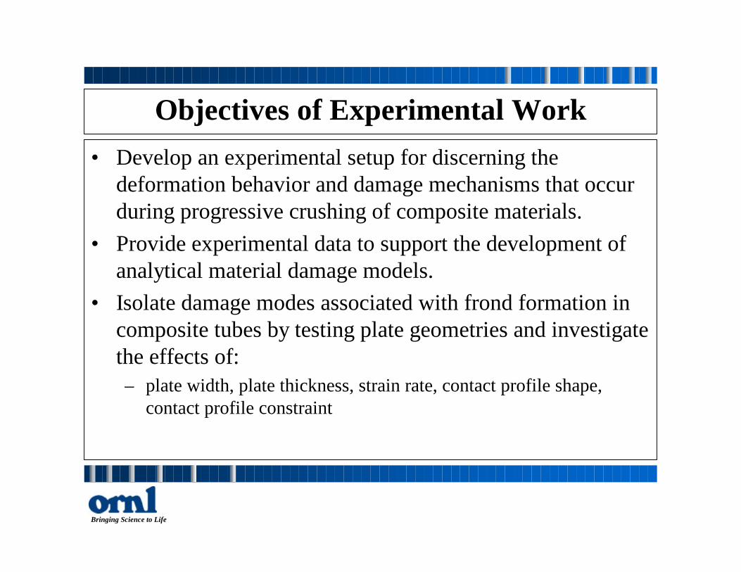
Objectives of Experimental Work• Develop an experimental setup for discerning the
deformation behavior and damage mechanisms that occurduring progressive crushing of composite materials.
• Provide experimental data to support the development ofanalytical material damage models.
• Isolate damage modes associated with frond formation incomposite tubes by testing plate geometries and investigatethe effects of:– plate width, plate thickness, strain rate, contact profile shape,
contact profile constraint
Bringing Science to Life
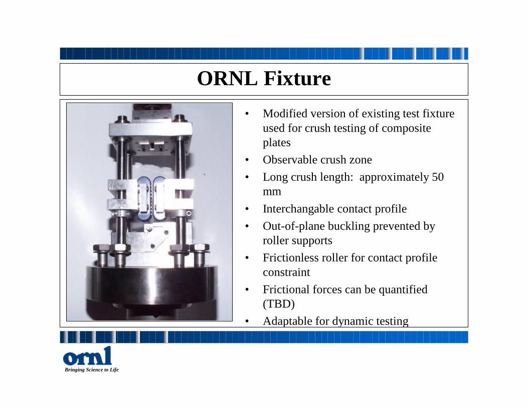
ORNL Fixture• Modified version of existing test fixture
used for crush testing of compositeplates
• Observable crush zone• Long crush length: approximately 50
mm• Interchangable contact profile• Out-of-plane buckling prevented by
roller supports• Frictionless roller for contact profile
constraint• Frictional forces can be quantified
(TBD)• Adaptable for dynamic testing
Bringing Science to Life
Roller Constraint Effect
• Fixture allows for activation ofdifferent damage mechanisms


![Mechanical Properties of Random Discontinuous Fiber ... · discussions about the properties of fiber-reinforced composites can be found in a lot of literature such as reference [1,2,3].](https://static.documents.pub/doc/80x56/5f5d1d70f1179361f1181733/mechanical-properties-of-random-discontinuous-fiber-discussions-about-the-properties.jpg)


