61
•
Loughborough UniversityInstitutional Repository
Impact of a cooled coolingair system on the externalaerodynamics of a gas
turbine combustion system
This item was submitted to Loughborough University's Institutional Repositoryby the/an author.
Citation: WALKER, A.D. ... et al, 2017. Impact of a cooled cooling air systemon the external aerodynamics of a gas turbine combustion system. Journal ofEngineering for Gas Turbines and Power, 139 (5), article no. 051504
Additional Information:
• This paper was published in the journal Journal of Engineering for GasTurbines and Power and the definitive published version is available athttp://dx.doi.org/10.1115/1.4035228.
Metadata Record: https://dspace.lboro.ac.uk/2134/23563
Version: Accepted for publication
Publisher: c© ASME
Rights: This work is made available according to the conditions of the Cre-ative Commons Attribution-NonCommercial-NoDerivatives 4.0 International(CC BY-NC-ND 4.0) licence. Full details of this licence are available at:https://creativecommons.org/licenses/by-nc-nd/4.0/
Please cite the published version.

AmericanSocietyofMechanicalEngineers
ASMEAcceptedManuscriptRepository
InstitutionalRepositoryCoverSheet
First Last
ASME Paper Title: Impact of a Cooled Cooling Air System on the External Aerodynamics of a Gas Turbine
Combustion System
Authors: A. Duncan Walker, Bharat Koli, Liang Guo, Peter Beecroft and Marco Zedda
ASME Journal Title: Journal of Engineering for Gas Turbines and Power
Volume/Issue _________________139 (5)___________ Date of Publication (VOR* Online) __10/01/2017______
ASME Digital Collection URL: http://gasturbinespower.asmedigitalcollection.asme.org/article.aspx?articleid=258746
DOI: 10.1115/1.4035228
*VOR (version of record)

Impact of a Cooled Cooling Air System on the External Aerodynamics of a Gas Turbine Combustion System
Walker et al. 1
Impact of a Cooled Cooling Air System on the External Aerodynamics of a Gas
Turbine Combustion System Walker, A Duncan Senior Lecturer, Loughborough University Department of Aeronautical and Automotive Engineering, Loughborough University, Loughborough, Leicestershire, LE11 3TU, UK. [email protected] Koli, Bharat Research Associate, Loughborough University Department of Aeronautical and Automotive Engineering, Loughborough University, Loughborough, Leicestershire, LE11 3TU, UK. [email protected] Guo, Liang Associate Professor, Jilin University Department of Internal Combustion Engines, Jilin University, Changchun, China, 130022 [email protected] Beecroft, Peter Rolls‐Royce plc SIN‐A‐65, Rolls‐Royce plc, PO Box 31, Moor Lane, Derby, DE24 8BJ, UK Peter.Beecroft@Rolls‐Royce.com Zedda, Marco Rolls‐Royce plc ML‐92, Rolls‐Royce plc, PO Box 31, Moor Lane, Derby, DE24 8BJ, UK Marco.Zedda@Rolls‐Royce.com

Impact of a Cooled Cooling Air System on the External Aerodynamics of a Gas Turbine Combustion System
Walker et al. 2
ABSTRACT
To manage the increasing turbine temperatures of future gas turbines a cooled‐cooling
air system has been proposed. In such a system some of the compressor efflux is diverted for
additional cooling in a heat exchanger located in the by‐pass duct. The cooled air must then be
returned, across the main gas path, to the engine core for use in component cooling. One option
is do this within the combustor module and two methods are examined in the current paper; via
simple transfer pipes within the dump region or via radial struts in the pre‐diffuser. This paper
presents an experimental investigation to examine the aerodynamic impact these have on the
combustion system external aerodynamics. This included the use of a fully annular, isothermal
test facility incorporating a bespoke 1.5 stage axial compressor, engine representative outlet
guide vanes, pre‐diffuser and combustor geometry. Area traverses of a miniature five‐hole probe
were conducted at various locations within the combustion system providing information on
both flow uniformity and total pressure loss. The results show that, compared to a datum
configuration, the addition of transfer pipes had minimal aerodynamic impact in terms of flow
structure, distribution and total pressure loss. However, the inclusion of pre‐diffuser struts had a
notable impact increasing the pre‐diffuser loss by a third and consequently the overall system
loss by an unacceptable 40%. Inclusion of a hybrid pre‐diffuser with the cooled cooling air bleed
located on the pre‐diffuser outer wall enabled an increase of the pre‐diffuser area ratio with the
result that the system loss could be returned to that of the datum level.
Keywords: gas turbine combustion system aerodynamics, pre‐diffuser, cooled‐cooling air, turbine
cooling.

Impact of a Cooled Cooling Air System on the External Aerodynamics of a Gas Turbine Combustion System
Walker et al. 3
INTRODUCTION Air traffic is expected to grow significantly over the next 20 years and, unless
new technology is introduced, this will negatively impact the environment due to
increased emissions of CO2, NOx, CO, Unburnt Hydrocarbons (UHC), and particulate
matter. Stringent legislation is in place to control the environmental impact of aviation,
against which aircraft and aero engines must be certificated. Even more challenging
targets have been set out for the long term future, for example in ACARE’s “Flightpath
2050” [1] document. As aero gas turbine designers strive for ever greater efficiencies
(and reduced fuel burn) the trend has been for engine overall pressure ratios (OPR) to
rise. Higher OPR allows greater thermal efficiencies and provides higher thrust for a
given core size. However, this also means that cycle temperatures increase. In modern
aero engines the compressor exit temperature is now higher than the turbine entry
temperature in early engines. This is a particular problem as compressor exit air is
routinely used to cool components in the combustion and turbine systems. Using higher
temperature air for cooling will reduce the operational life of these critical parts or
require unacceptably high cooling flows, which will negate the ultimate goal of a
reduction in specific fuel consumption. Additionally, the drive towards lean‐burn
combustion systems, in order to reduce NOx emissions, is accompanied by new
problems at the combustor/turbine interface. Firstly, to enable lean operation the
availability of cooling air will be reduced; current engines currently require as much as
20‐30% of the compressor delivery air to be diverted for component cooling. Secondly,
the exit temperature traverse from a lean‐burn system differs from that found in

Impact of a Cooled Cooling Air System on the External Aerodynamics of a Gas Turbine Combustion System
Walker et al. 4
traditional rich‐burn combustors in several ways. Significantly increased swirl and a
much flatter traverse are found, due to the larger fraction of combustor feed air being
diverted to the fuel injector, and the corresponding absence of dilution jets in lean‐burn
designs. In summary, these changes make the task of cooling the highly thermally
loaded turbine (both nozzle guide vane and rotor) considerably more difficult.
COOLED COOLING AIR SYSTEM
In order to achieve acceptable turbine cooling one suggested solution is for some
of the compressor efflux to be diverted for additional cooling in a heat exchanger (HX)
cooled by air from the engine’s by‐pass duct before being ducted for use in turbine
cooling. The design of this so‐called cooled cooling air (CCA) system itself poses many
challenges, which have been given very little attention to date. A CCA system can be
broken into three aerodynamic sub‐systems each with their own set of requirements
and challenges. See Fig. 1 [2].
Heat Exchanger
Concept studies suggest the use of a number of discrete core‐mounted HX units
with the exact number and size determined by the airflow and cooling requirements.
The HX will need to be compact and light‐weight, be fed by a relatively uniform flow and
have a high efficiency thereby maximizing the cooling for a given size/weight. The HX
system must also be robust as it constitutes additional equipment added to the engine
hence a risk of reduced reliability. Currently it is thought that tube/shell type HX will be
most suitable.

Impact of a Cooled Cooling Air System on the External Aerodynamics of a Gas Turbine Combustion System
Walker et al. 5
Low Pressure System
The low pressure (LP) system delivers air bled from the bypass duct for use as a
heat sink. The challenge here is to design a number of off‐takes with a high ram
recovery ratio and low total pressure loss. The flow must be significantly diffused prior
to the HX in order to minimize loss. Simple off‐takes are reasonably well understood in
terms of ram recovery ratio but there is very limited data on the design of diffusing off‐
takes and how to generate a uniform efflux. There is also a need for improved
understanding of component interaction. For example, A’Barrow et al. [3] demonstrated
a two‐way coupling in a diffusing annular off‐take situated in close proximity to the fan
OGV. The off‐take can influence the flow within the vane row and the condition of the
OGV exit flow will dictate the attainable level of diffusion in the off‐take. Additionally,
the off‐take must not compromise the bypass flow as any losses (e.g. spillage drag)
introduced here could have a significant effect on engine performance.
High Pressure System
The high pressure (HP) system delivers the hot core engine air to the HX and
then returns the cooled air, across the main gas path, for use in component cooling. The
simplest location to remove the HP air would be bleed off‐takes positioned on the
combustion chamber outer casing (CCOC) with the number of off‐takes required being a
function of the number of HX (i.e. the cooling requirements). It is likely that several HX
units will be required with each being supplied via individual off‐takes. Downstream of
the off‐takes the HP air will then be ducted to‐and‐from the HX with the design of this
ducting system being crucial if CCA is to be successful. These ducts must be compact,

Impact of a Cooled Cooling Air System on the External Aerodynamics of a Gas Turbine Combustion System
Walker et al. 6
lightweight and easy (cheap) to manufacture. They must also deliver a uniform flow
distribution to the HX and to the downstream components. All this must be done with
the minimum possible total pressure loss. Hence the design of the off‐take duct, the HX
manifolds and the return ducting must be managed carefully.
In order to deliver the cooled HP air to the core of the engine, where it will
follow a more‐or‐less conventional path to cool the various HP turbine components, it
must first cross the main gas path. This is significant as it has the potential to adversely
affect the aerodynamics of the core engine flow. It is vitally important that a CCA system
is integrated into the combustion system architecture without having a negative impact
on performance. Consequently this paper focusses on examining how this can be
achieved and the resulting impact on the combustion system aerodynamics (flow
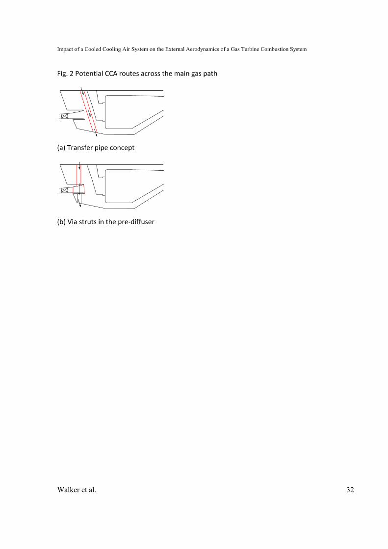
uniformity and total pressure loss). Two proposed methods of the transferring the CCA
across the main gas path are examined: (1) through simple transfer pipes located in the
dump region of the combustor, and (2) through radial struts in the pre‐diffuser. See Fig.
2.
To date there has been no notable published work on the effects of pipework
extending across the dump gap of a combustor. However, several studies have
examined the effect of downstream blockage on the upstream pre‐diffuser. For
example, the work of Fishenden and Stevens [4], Bailey et al. [5] and Walker et al. [6]
have shown that the pressure field generated by the flame tube can help to stabilize the
diffuser flow and enable higher area ratios to be achieved. More recently the work of

Impact of a Cooled Cooling Air System on the External Aerodynamics of a Gas Turbine Combustion System
Walker et al. 7
Walker et al. [7, 8] showed that for lean burn combustors the diffuser can be subjected
to both circumferential and radial variations of the pressure field by the downstream
geometry. With smaller dump gaps the circumferential variation was observed to
adversely affect the upstream rotor whilst at higher dump gaps although the rotor was
unaffected the beneficial blockage effect from the flame tube disappeared.
In general the inclusion of struts in the pre‐diffuser has a negative effect on the
combustion system aerodynamics. The overall area ratio of the pre‐diffuser decreases
and, with the subsequent increase in diffuser exit velocity, the system loss will increase.
It is not common practice to area weight strutted pre‐diffusers in order to recover this
“lost” area because the confluent boundary layers at the strut‐diffuser wall interface are
more susceptible to flow separation. Additionally the presence of struts can generate
upstream and downstream interactions. If the struts are too close to the upstream rotor
or their leading edge too large then the upstream pressure field will alter the
compressor performance. This effect is commonly seem in compressor transition ducts
were the struts are relatively large (see Walker et al. [9]). Downstream, the wakes
generated by the struts introduce non‐uniformity into the combustor flow field and this
can negatively impact feed to various features, not least the fuel injectors. Barker and
Carrotte [10] reported that the vortex shedding frequency from the struts could be
measured within the flame tube with velocity variations of up to 15% observed
downstream of the fuel injectors. Clearly this will have an impact on the fuel/air mixing
and combustion process.

Impact of a Cooled Cooling Air System on the External Aerodynamics of a Gas Turbine Combustion System
Walker et al. 8
OBJECTIVES The main objective of the current paper is to examine the impact of CCA transfer
pipes and struts on the aerodynamics of a generic lean burn combustion system. A
second objective is to investigate if the CCA bleed flow can be utilised to provide a
beneficial aerodynamic effect (e.g. a bled pre‐diffuser) and increase the area ratio of the
strutted pre‐diffuser back to its original value.
Of particular interest to the work is the effect on total pressure loss and flow
uniformity at OGV exit, pre‐diffuser exit, in the combustor annuli and the feed to the
fuel injectors. Minimal impact on total pressure loss is crucial as this is closely linked to
cycle performance and overall specific fuel consumption. Flow uniformity is similarly
important as it is dictates the quality of feed to important features within the
combustions system (fuel injectors, cooling flows etc.). These metrics will be assessed
experimentally on a fully annular isothermal test facility via detailed area traverses of a
miniature five‐hole probe.
FULLY ANNULAR ISOTHERMAL TEST FACILITY An existing experimental facility was used and modified accordingly (Fig. 3 and
4). Housed within the Department of Aeronautical and Automotive Engineering at
Loughborough University this rig comprises of a fully annular isothermal representation
of a modern combustion system from the last stage of the HP compressor through to
the inlet of the turbine. The test rig is mounted vertically to the test cell floor with

Impact of a Cooled Cooling Air System on the External Aerodynamics of a Gas Turbine Combustion System
Walker et al. 9
filtered ambient air delivered to an under‐floor plenum chamber via a large centrifugal
fan. The air passes through a honeycomb flow straightener and is then accelerated over
a bell‐mouth intake prior to entering into the test rig.
It is widely acknowledged that the inlet conditions presented to a combustor
pre‐diffuser have a crucial influence on its performance. The importance of compressor
exit conditions has been well characterized by, for example, Stevens et al. [11], Klein
[12], Zierer [13], Carrotte et al. [14], and Barker and Carrotte [15, 16]. Downstream of an
axial compressor pre‐diffusers have been shown to achieve a considerably higher
pressure recovery than with “clean” ducted‐flow inlet conditions. This is due to the high
levels of turbulence and secondary flow structures generated by the rotor and OGV.
Hence, the test facility uses a bespoke 1½ stage axial flow compressor which provides a
good compromise in terms of capturing the unsteady blade wakes, secondary flows and
rotor tip leakage flows that will have an important influence on downstream
components whilst avoiding the costs associated with a multi‐stage compressor.
It is important to note that two different build standards of compressor and OGV
were used in this work due to other test programmes running on the rig. However, as
will be seen, this did not prevent back‐to‐back comparisons of the various concepts with
a datum configuration.
Design of the 1½ stage axial flow compressor was undertaken in conjunction
with Rolls‐Royce plc. The philosophy in this type of test facility is to design a bespoke
inlet guide vane (IGV) and rotor which will provide the correct inlet conditions (radial

Impact of a Cooled Cooling Air System on the External Aerodynamics of a Gas Turbine Combustion System
Walker et al. 10
profiles of total pressure and flow angles) to an engine representative OGV. The IGV and
the rotor are not intended to directly represent engine components. However, the OGV
are designed to experience nominally the same loading, in terms of DeHaller number,
diffusion factor, hub/tip ratio and inlet/exit swirl angle as a typical engine OGV. Ideally,
the flow in the test facility would be such that the engine non‐dimensional mass flow
( √ / ) and compressor blade Reynolds number are faithfully reproduced. However,
rig temperatures and pressures are low and these operating conditions cannot be
achieved. To ensure dynamic similarity with the engine aerodynamics the test rig mass
flow is set sufficiently high to ensure the OGV Reynolds number, based on the chord, is
greater than 1.9 x 10⁵. According to Cumpsty [17] this means that boundary layer
transition occurs early enough to ensure that the OGV exit flow (unsteady wakes and
secondary flows) are fully representative. The compressor was operated at a fixed non‐
dimensional mass flow and non‐dimensional rotor speed. At standard day conditions
this amounts to a design speed of 4500 rpm ( /√ = 265) and flow co‐efficient
( / ) of 0.543. This provides an air mass flow rate of approximately 3.3kg/s,
an inlet Mach number of 0.21 and an OGV Reynolds number of 2.0 x 10⁵.
During operation of the rig a centrifugal fan, which is located in series with the
test rig, is initially used to assist in starting the compressor and then subsequently to
maintain the desired flow coefficient and mass flow rate. The operating condition of the
axial flow compressor is monitored using three Furness FCO44 pressure transducers.
Two of these record the inlet total, static and hence dynamic pressure giving the inlet
velocity and mass flow. The third provides a reference gauge pressure at a suitable

Impact of a Cooled Cooling Air System on the External Aerodynamics of a Gas Turbine Combustion System
Walker et al. 11
location within the test section. A single K‐type thermocouple provides the inlet
stagnation temperature ( ). Using these measurements, the compressor non‐
dimensional speed and flow coefficient can be maintained to within ±0.08% and ±0.18%
respectively of their prescribed values for the duration of the experiment.
Instrumentation, Data Reduction and Errors
Throughout the test programme aerodynamic data were recovered using
miniature five‐hole pressure probes. Suitably calibrated and employed in the non‐nulled
mode, in line with Wray et al. [18], these provide the time‐averaged local flow vector
and total and static pressures. The probes could be traversed radially and
circumferentially such that area traverses were constructed over repeatable sectors at
OGV exit (A), pre‐diffuser exit (B) and in the combustor annuli (C2 and E2) – refer to Fig.
4. For example, over an OGV the area traverse was constructed from 21x21 radial and
circumferential measurement points with increased density in regions of interest such
as the OGV wakes and boundary layers. From the five‐hole probe data, at any given
plane, spatially averaged values were obtained through suitable averaging. For example,
the velocity normal to the traverse plane, Ū, was obtained by area‐weighting the
individual values whilst the total, , and static, , pressures were mass‐weighted using
the technique described by Klein [19]. Changes in the spatially averaged pressures
between any two planes are then expressed in terms of a total pressure loss, , and
static pressure rise coefficient, , with the change in pressure being made non‐
dimensional by a suitable reference dynamic head, for example:
Impact of a Cooled Cooling Air System on the External Aerodynamics of a Gas Turbine Combustion System
Walker et al. 12
(1)
(2)
The pressures measured were estimated to be accurate to within 1%. The total
velocity of the flow was obtained from the dynamic pressure, and hence the accuracy of
the local velocities was within ±0.5%. Whilst the pitch angle of the flow was determined
from the calibration of the probe, additional errors in yaw angle could arise associated
with the ability of the user to align the probe with the rig centre line. It is estimated that
this could be set to within 1°, and this level of accuracy was reflected in the measured
swirl angles and circumferential component of velocity. In addition to the errors
associated with the local measurements it was estimated that the mass weighted total
and static pressures at a given traverse plane were repeatable to better than 10 Nm‐2.
Thus, the repeatability of the derived total pressure loss and static pressure rise
coefficients was better than ±0.005. Additionally, the calculated mass flows at each
traverse plane, derived from the velocity measurements, were all within 1% of each
other. All measurements were corrected to ISA standard day conditions.
TEST SECTIONS
The fuel injectors and flame tube are representative of current and near term
lean burn technology for medium to large civil aero engines. The injectors were
produced via additive manufacturing and contain all the aerodynamic surfaces and
passages exposed to the airflow but do not contain the internal fuel passages. Although
engine Reynolds numbers are not achieved the facility runs at a sufficiently high

Impact of a Cooled Cooling Air System on the External Aerodynamics of a Gas Turbine Combustion System
Walker et al. 13
Reynolds number such that the effective area of the injector is replicated. The flow splits
to the combustor and annuli are controlled by metered orifice plates downstream of the
test section. To reduce complexity and cost the flame tube cooling flows are not
represented.
In order to characterize the aerodynamic impact (effect on total pressure loss
and flow uniformity) of adding CCA to the combustion system several different test
section configurations were used. It is important to note that two different
compressor/OGV builds were also used in this work due to other projects utilizing the
test facility. The first build standard was used to investigate the influence of transfer
pipes and the second to examine the effect of including radial struts in the pre‐diffuser.
(The combustor geometry remained unchanged throughout).
Datum 1 OGV/Pre‐Diffuser
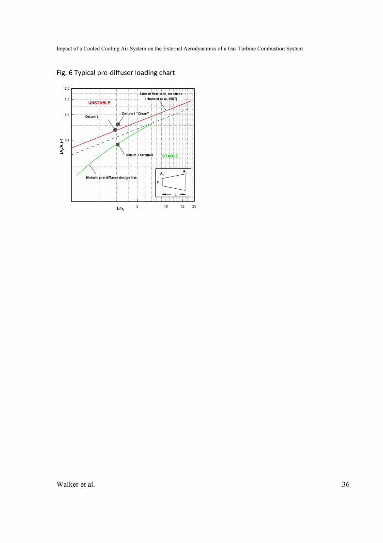
This clean un‐strutted pre‐diffuser is representative of current system
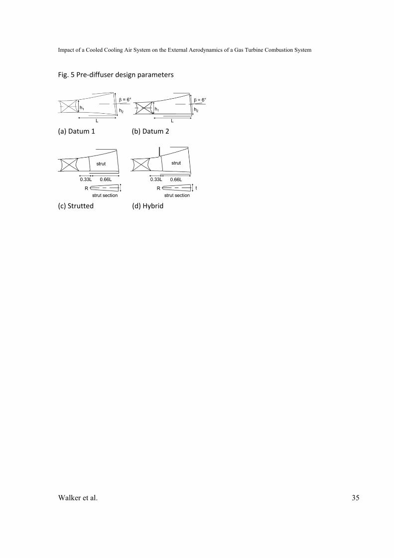
architecture with no CCA. It has an area ratio of 1.77 and a non‐dimensional length of
3.1 (see Fig. 5a and Table 1). It is of conventional design and with reference to the
loading chart shown in Fig. 6 sits slightly above the “line‐of‐first‐stall” (as determined
experimentally by Howard et al. [20] for diffusers with fully developed inlet conditions).
In gas turbines this “line‐of‐first‐stall” does not really represent a limit as the inclusion of
compressor generated inlet conditions (as discussed previously) enables the pre‐diffuser
to operate closer to, and often above, the perceived stall margin due to the increased
turbulence and secondary flows generated by the OGV row.

Impact of a Cooled Cooling Air System on the External Aerodynamics of a Gas Turbine Combustion System
Walker et al. 14
Transfer Pipes
As shown in Fig. 7 the transfer pipe concept represents the simplest way of
transferring the cooled air across the main gas path. However, from an aerodynamic
perspective this concept may intuitively be unattractive as they clearly present an
obstacle to the flow; although the pipes are positioned between fuel injectors. The
number, size and location of the pipes are ultimately a compromise between the
quantity of CCA, mechanical space constraints in the engine and the need to minimise
their impact on the system aerodynamics. In the current configuration 4 equally spaced
¾ inch pipes were employed. Again note that these pipes only serve to replicate the
external aerodynamics and do not model the internal CCA flow.
Datum 2 OGV/Pre‐Diffuser
In comparison to Datum 1 this pre‐diffuser in its clean, un‐strutted configuration
has a slight reduction in area ratio to 1.67 as seen in Fig. 5b and 6.
Strutted Pre‐Diffuser
This included the addition of radial struts (Fig. 5c) through which the CCA is
returned to the engine core. It is thought that, provided the OGV carry some/most of
the radial loads then these strut can remain aerodynamically thin (t/h2 ~ 0.3) and still
pass the required level of CCA. However, inclusion of the struts reduces the pre‐diffuser
area ratio from 1.67 to 1.45. Note also that the internal airflow of the strut was not
modelled; this investigation is concerned with the combustion system external
aerodynamics only.
Impact of a Cooled Cooling Air System on the External Aerodynamics of a Gas Turbine Combustion System
Walker et al. 15
Hybrid Pre‐Diffuser
The reduction in pre‐diffuser area ratio due to the inclusion of radial struts will
ultimately have a negative impact on the downstream combustion system. For a first
order approximation the total pressure loss in the system is a function of the square of
the diffuser exit velocity. As such, a reduction in area ratio for the Datum 2 pre‐diffuser
from 1.67 to 1.45 has the potential to increase loss by approximately one third. Diffuser
design is always driven by the need to maximise the area ratio in order to minimise loss.
However, the absolute area ratio is limited by the boundary layer’s ability to tolerate
high adverse pressure gradients without separating. As seen in Fig. 6 the current diffuser
has the maximum feasible area ratio within current design rules. A longer diffuser could
be employed but this adds to system length and weight negating any aerodynamic
performance advantage. Hence, if radial struts are to be used to transfer the CCA, some
alternate approach must be adopted to recover the datum area ratio and reduce losses.
A further aim of the current work was to determine if the CCA bleed flow could
be utilised in some way to do this. Consequently, a hybrid bled diffuser was designed
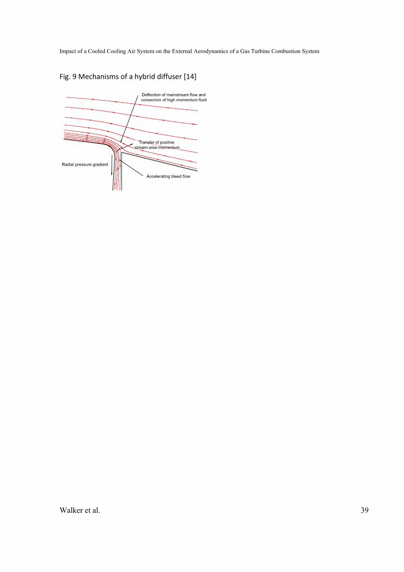
based on the work of Walker et al. [21, 22]. This hybrid diffuser (Fig. 8) utilises the bleed
flow in a specific manner which enables the boundary layer to remain attached under
aerodynamic loading that would normally result in separation. Thus much higher pre‐
diffuser area ratios can be achieved. The controlling flow mechanism is not a simple
boundary layer bleed but involves a more complex interaction between the accelerating
bleed flow and the diffusing mainstream flow. The two governing processes are
indicated in Fig. 9. Firstly, the bleed flow gains streamwise momentum as it accelerates
Impact of a Cooled Cooling Air System on the External Aerodynamics of a Gas Turbine Combustion System
Walker et al. 16
into the bleed duct. A turbulent shear layer exists between the accelerating bleed flow
and the diffusing mainstream flow. Streamwise momentum is transported, across this
layer, to the diffusing mainstream flow, re‐energizing it and enabling it to remain
attached on the high angle downstream wall. Secondly, the radial pressure gradient
created by the bleed causes deflection of the mainstream flow and enhances further the
transport of higher momentum fluid into the boundary layer.
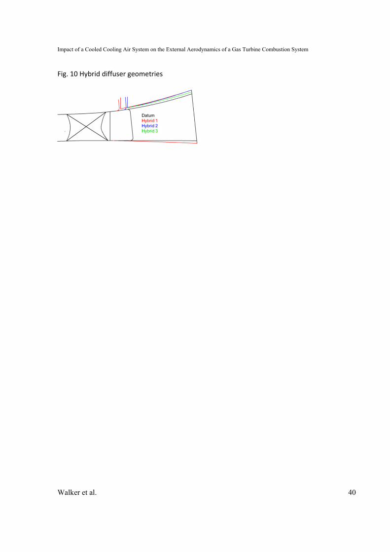
An initial design of hybrid diffuser was specified from the guidelines presented
by Walker et al. [21, 22]. The aim was to return the strutted area ratio to that of the
datum clean pre‐diffuser (1.67) which meant that without struts the hybrid diffuser
would have a clean area ratio of approximately 1.93. However, it was unclear as to the
optimal location of the bleed slot with respect to the OGV and the strut. Thus as shown
in Fig. 10 the initial design (Hybrid 1) located the bleed mid‐way between the two and
CFD was used to assess this initial design. In order to minimise the computational
expense the CFD model was limited to a single OGV sector of the pre‐diffuser and did
not include the OGV, the struts or downstream combustor (Fig. 11). The numerical
methodology employed was typical of that used extensively in the Loughborough
University Rolls‐Royce UTC for the design and analysis of pre‐diffuser flows. Grid
generation was accomplished using ANSYS Gambit to produce a quadrilateral block
structured mesh. Prism layers were employed to ensure a high near wall cell density
with y+ values of ~1‐2 in order to fully resolve the boundary layer flow. Solution of the
RANS equations was performed using ANSYS Fluent with a k‐ SST turbulence model.
Representative inlet conditions were taken from experimental measurements

Impact of a Cooled Cooling Air System on the External Aerodynamics of a Gas Turbine Combustion System
Walker et al. 17
performed on the datum pre‐diffuser. The five‐hole probe measurements gave the
velocity vector and turbulence data were calculated by specifying suitable variations in
turbulence intensity and length scale (i.e. from experience and previous experiments).
Predicted contours of axial velocity presented in Fig. 11 show that at 4% bleed
the diffuser flow separates. This was surprising as the previous work of Walker et al. [21,
22] and some preliminary 2D axisymmetric predictions suggested that in this
configuration the flow would remain attached. Flow separation occurs in line with the
OGV wake as the low‐momentum wake fluid is unable to overcome the increased
adverse pressure gradient.
Examination of the radial velocity shown in Fig. 12 suggests that the flow
mechanism of the hybrid diffuser is adversely affected by the OGV wakes. The low
momentum wake fluid is easily captured by the bleed off‐take but does not accelerate
as much as the bulk‐flow. Thus, in the region of the wake the bleed flow does not impart
sufficient momentum into the new boundary layer as it forms on the downstream wall.
Ergo the flow mechanism of the hybrid diffuser breaks down. Ultimately the data
suggest that the bleed slot is too close to the OGV and more axial distance is required to
allow the wake to mix out more. As such, a further design iteration (Hybrid 2) was made
in which the bleed slot was moved immediately upstream of the strut location (see Fig.
10. Although this improved the flow Fig. 13 shows that the pre‐diffuser is still close to
separation in line with the OGV wake. It was not possible to move the bleed slot any
further downstream (to allow for additional wake mixing) due to the strut location.
Impact of a Cooled Cooling Air System on the External Aerodynamics of a Gas Turbine Combustion System
Walker et al. 18
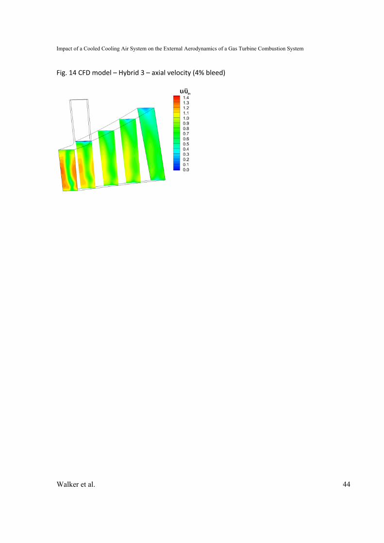
Consequently the outer wall loading was slightly relaxed by reducing the overall ratio to
1.61 (equivalent to 1.83 without struts). Fig. 14 shows that the predicted flow was now
fully attached on the outer wall. Hence this design (Hybrid 3) was taken forward for
experimental evaluation on the fully annular test rig.
EXPERIMENTAL RESULTS AND DISCUSSION Mean Flow Field Datum 1 OGV/Pre‐Diffuser ‐ Transfer Pipes
Contours of axial velocity obtained from 5‐hole probe area traverses at OGV exit
(A) are presented in Fig. 15 with and without the transfer pipes fitted. Contours are
plotted over a 4 OGV sector with the transfer pipe aligned centrally. The plots are
characterized by OGV wakes but clearly show negligible difference when the transfer
pipes are added. At pre‐diffuser exit (B) there is again no discernable influence of the
transfer pipes on the flow. Fig. 15 shows contours of axial velocity over a single fuel
injector sector with the transfer pipes located centrally and the fuel injectors at the
sector extremities. OGV wakes are still present but have mixed out somewhat. It is also
interesting to note that the fuel injectors have no clear upstream effect on the flow at
diffuser exit. This is in contrast to observations by Walker et al. [7, 8] and is due to a
relatively large dump gap in the current study.
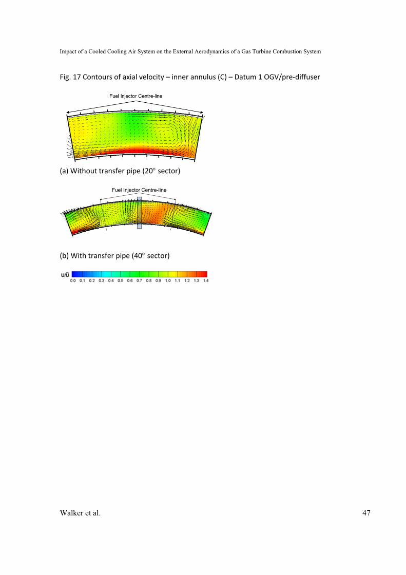
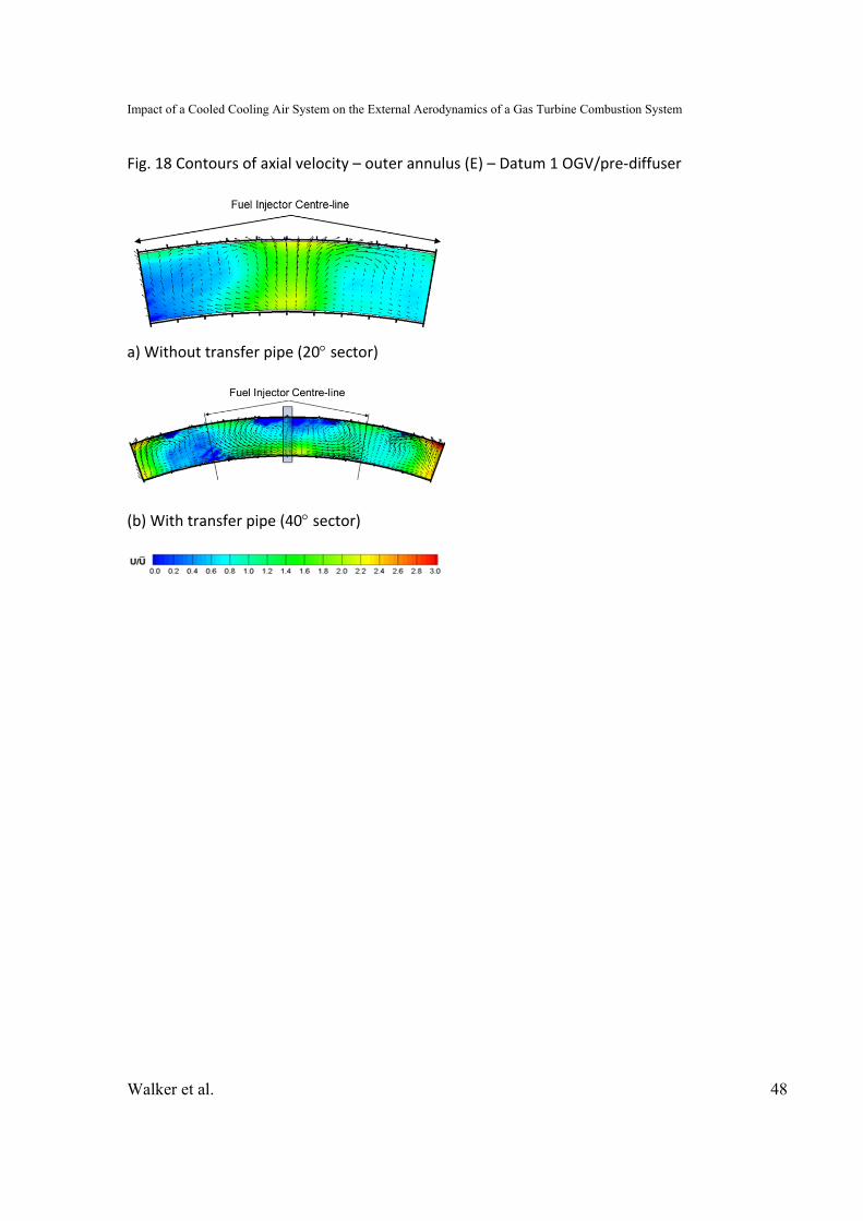
The flow path to the combustor annuli is complex (see for example Ford at al.
[23]). Axial velocity contours and secondary vectors in the feed annuli are shown in Fig.
17 and 18. Note that with the transfer pipes fitted the measurement sector extends a

Impact of a Cooled Cooling Air System on the External Aerodynamics of a Gas Turbine Combustion System
Walker et al. 19
further 10 either side in order to examine how far the influence of the pipes extends.
The plots show that the flow is non‐uniform with regions of high/low velocity generated
through interaction with the fuel injectors [23]. The pre‐diffuser efflux undergoes free
expansion into the dump cavity; there is strong interaction between various stream
tubes and shear layers and strong dump vortices are established. There is also a bias
generated by the curvature in the dump and around the flame tube head. Furthermore
the curvature generates two counter rotating vortices in the free‐shear layer due to
Taylor‐Goertler type instabilities and these vortices are clearly visible in vector plots.
The addition of the transfer pipes generates some increase in the non‐uniformity of the
flow in the annuli. However, this is relatively small in comparison to the existing non‐
uniformities.
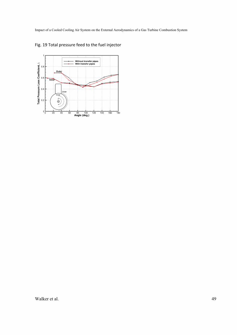
In order to assess any potential impact caused by the transfer pipes on the feed
to the injector an array of total pressure tappings were attached to one of the injector
models. These were located on the half of the injector closest to a transfer pipe with 10
tappings positioned to assess the flow in the main inner and outer swirlers. The total
pressure is plotted in Fig. 19 as a non‐dimensionalised loss coefficient both with and
without the transfer pipes. Zero degrees correspond to the location of the burner feed
arm. Again the data suggest that, although this is a relatively crude measurement, the
introduction of the transfer pipes makes almost no difference to the inner swirler and
only a negligible difference to the outer swirler.

Impact of a Cooled Cooling Air System on the External Aerodynamics of a Gas Turbine Combustion System
Walker et al. 20
Datum 2 OGV, Strutted and Hybrid Pre‐Diffuser
Fig. 20 shows contours of axial velocity, measured over a full 8 OGV strut‐to‐strut
sector, at OGV exit (A). The data show no measurable difference in the OGV exit flow
field between the clean, strutted and hybrid pre‐diffusers. Previous work (see for
example Walker et al. [7, 8, 9]) has shown that the potential field can have a significant
upstream effect and modify the performance of the OGV. However, here the struts are
sufficiently slender such that this does not happen. Nevertheless, at pre‐diffuser exit (B)
the effect of the struts is obvious (Fig. 21). In general for the Datum 2 diffuser the flow
has a general hub bias generated by the outboard cant of the pre‐diffuser which
increases the aerodynamic loading on the outer wall. The result is that the outer wall
boundary layer is much more developed and closer to separation, although for the clean
pre‐diffuser (Fig. 21a) the flow is remains fully attached. With the addition of struts the
pre‐diffuser area ratio is reduced and the flow profile becomes more “peaky” with an
increase in the maximum velocity. Importantly the flow still shows no evidence of flow
separation. A weakness of strutted pre‐diffusers is the end‐wall / strut interface where
the confluent boundary layers are more prone to separation. However, despite the
relatively high loading on the outer wall the velocity contours do not show any strong
evidence of a corner stall. The inclusion of struts does constrain the flow somewhat and
reduces the mean yaw (swirl) angle from ~5° to 2° (Fig. 22). This reduction in angle is
potentially beneficial in terms of the feed to the downstream fuel injectors which are
generally designed for axial flow.

Impact of a Cooled Cooling Air System on the External Aerodynamics of a Gas Turbine Combustion System
Walker et al. 21
For the hybrid diffuser Fig. 23 compares predicted and measured axial velocity
contours at diffuser exit from 0‐3% bleed. There is reasonable agreement between the
design CFD and the final experimental results. The CFD slightly under predicts both the
low velocity region on the outer wall and the wake mixing (hence a deeper OGV wake)
but generally the flow topology is well represented. Without bleed the flow has
arguably separated from the outer wall, with 2% bleed the flow is now fully attached
and with 4% bleed the condition of the outer wall flow is much improved. It is likely that
some further increases in bleed may give additional improvements to the outer wall
flow but Walker et al. [21, 22] suggested that there are diminishing returns. For this
investigation the amount of bleed was limited to 4% as a practical upper limit for
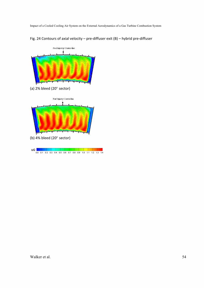
currently proposed cooled cooling air systems. For completeness, measured axial
velocity contours for a 40° sector traverses with 2% and 4% bleed as shown in Fig. 24. In
both cases there is some suggestion of a small corner stall at the outer casing junction
with the central strut. However, the circumferentially averaged velocity profile shown in
Fig. 22 clearly shows an improvement in the outer wall boundary layer at the higher
bleed rate. Also evident in the profiles is an increase in the pitch angle at higher bleed
rates. This was also observed by Walker et al. [21, 22] who suggested bleed could also
be used to help turn the flow more effectively in canted systems. Although the effect
here is small; +2° at 2% bleed and +3° at 4% bleed.
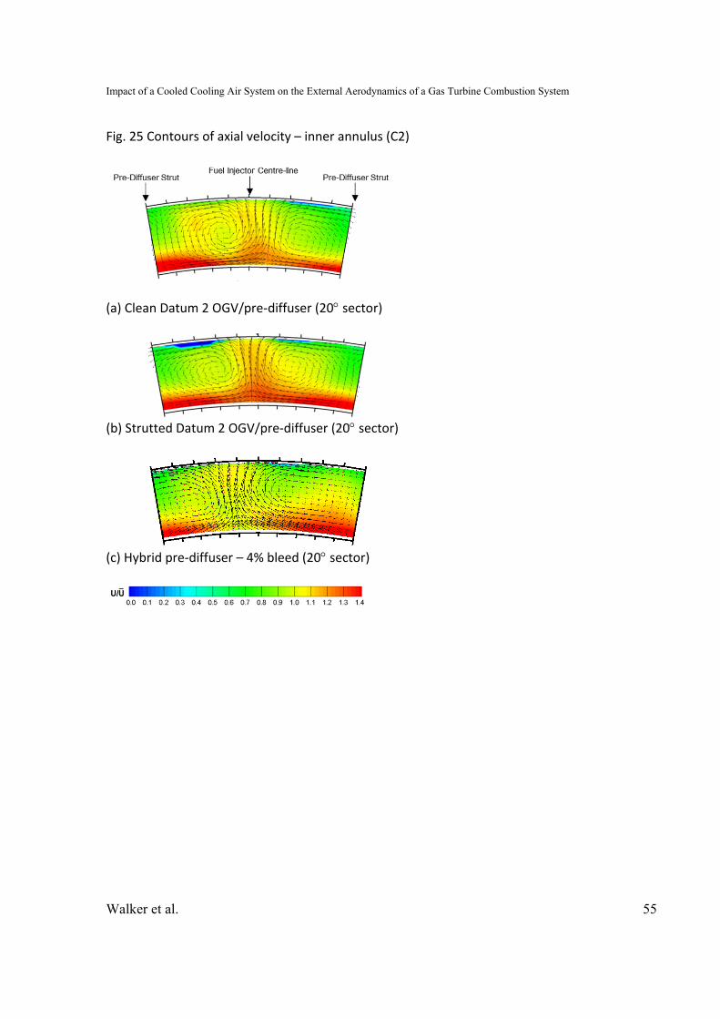
Measured axial velocity contours in the combustor annuli (C2 and E2) are shown
in Fig. 25 and 26. As discussed earlier the flow path to the annuli is complex and results
in a highly non‐uniform and biased flow. This is particularly noticeable in the outer
Impact of a Cooled Cooling Air System on the External Aerodynamics of a Gas Turbine Combustion System
Walker et al. 22
annulus and is reflected (i) by the much wider range in the contour legend and (ii) a
number of null or off‐calibration data points (deep blue regions). The five‐hole probe
can only resolve flow angles of ±36° and these regions represent either high yaw angles
or high pitch angles as the flow negotiates the cowl curvature. However, they could also
potentially suggest small regions of separated or reversed flow. With the addition of
pre‐diffuser struts the annulus flow structure remains broadly similar but, with the
increased diffuser exit velocity, the flow is less able to negotiate the cowl curvature. The
result is a slight increases the level of non‐uniformity; although in relation to the existing
non‐uniformity this is perhaps marginal. The effect is worse in the outer annulus as can
be seen by the increase in null data points.
For the hybrid pre‐diffuser the inner annulus flow improves slightly returning the
uniformity to that seen in the clean pre‐diffuser. This is unsurprising as the hybrid pre‐
diffuser increases the area ratio from that of the strutted system back to that of the
clean pre‐diffuser. However, with the hybrid diffuser the outer annulus flow shows
significant improvements in uniformity. This is initially surprising as the hybrid diffuser
has only a comparable area ratio to the clean pre‐diffuser. However, it does have an
increased outer wall divergence angle, an increase in the flow pitch angle and an
effective increase in the maximum local area ratio (i.e. between struts). It is these
factors that are responsible for the notably improved flow field in the outer annulus.

Impact of a Cooled Cooling Air System on the External Aerodynamics of a Gas Turbine Combustion System
Walker et al. 23
System Performance and Loss Datum 1 OGV/Pre‐Diffuser ‐ Transfer Pipes
Fig. 27 graphically illustrates the effect of the transfer pipes on the mass‐
weighted total pressure loss, , and static pressure recovery, Cp, coefficients. These are
quoted at pre‐diffuser (B) exit and within each annulus (C2 and E2) with respect to OGV
exit (A) – see equations (1) and (2). With the minimal change observed in the measured
flow field it is unsurprising that the addition of the transfer pipes has negligible effect on
these coefficients and the overall system performance.
Datum 2 OGV, Strutted and Hybrid Pre‐Diffuser
Fig. 28 shows that the inclusion of struts and the resultant increase in wetted
area causes the pre‐diffuser total pressure loss to rise. Similarly the reduction in area
ratio results in a reduced static pressure recovery although the pre‐diffuser
effectiveness remains nominally unchanged. (Diffuser effectiveness is given by
/ ′ where the ideal static pressure recovery is 1 . More
significant, however, is the increase in loss in the annuli due to the reduced pre‐diffuser
area ratio and increased velocity of the pre‐diffuser efflux. Not only will this affect the
ability of the annulus flows to feed cooling air to the combustor walls and/or nozzle
guide vanes but, ultimately, increased annulus losses will increase the overall pressure
drop of the combustion system which will have a negative effect on the engine cycle and
the fuel burn.

Impact of a Cooled Cooling Air System on the External Aerodynamics of a Gas Turbine Combustion System
Walker et al. 24
For the hybrid pre‐diffuser loss is a little higher than the strutted datum pre‐
diffuser. This is not surprising as it has a similar wetted area and with the higher area
ratio should also incur more loss due to increased levels of diffusion. Interestingly at the
higher bleed rate the loss in the hybrid pre‐diffuser marginally reduces. This is because
the higher bleed (i) removes some of the low quality flow and (ii) improves the
effectiveness of the diffusion process. However, the increased area ratio of the hybrid
pre‐diffuser has a significant effect in the annuli. As expected the loss reduces and is
now only fractionally above the datum loss. This confirms that the hybrid pre‐diffuser
was successful in its goal of using the bleed to gain an aerodynamic advantage;
increasing the pre‐diffuser area ratio and thereby reducing the system loss (or at least
returning it to datum levels.
CONCLUSIONS
An isothermal experimental has been undertaken to assess the impact on the
combustor external aerodynamics of incorporating a cooled cooling air system. Two
methods of returning the cooled HP air across the main gas path have been examined;
via simple transfer pipes in the dump region or via radial struts in the pre‐diffuser.
Measurements have shown that, for the proposed configuration, the inclusion of
four 0.75” transfer pipes has negligible aerodynamic impact in terms of flow structure,
distribution and total pressure loss. Consequently, for an aerodynamic perspective the
simple transfer pipe option is an attractive solution. However, the current study does

Impact of a Cooled Cooling Air System on the External Aerodynamics of a Gas Turbine Combustion System
Walker et al. 25
not examine any thermo‐mechanical implications or the fact that transfer pipes may not
be a viable option in all engines if there is insufficient space in the dump region.
With the addition of radial struts to a datum clean pre‐diffuser there was no
evidence flow separation (a known weakness of strutted pre‐diffusers). However, the
measured pre‐diffuser total pressure loss increased by a third and, more importantly,
the reduction in area ratio (and hence diffusion) resulted in an unacceptable increase in
overall system loss (by up to 40%). Simply adding radial struts to an existing pre‐diffuser
is not therefore an attractive option as it will increase the loss in the combustion system
which will ultimately have a negative impact on overall engine fuel burn.
The use of a hybrid pre‐diffuser with the CCA bleed located on the pre‐diffuser
outer wall enabled an increase of the pre‐diffuser area ratio returning it to a value close
to that of the datum clean design. With no bleed the pre‐diffuser flow was, as expected,
separated from the outer wall. However, at 2% bleed the flow was fully attached and at
4% the outer wall boundary layer showed further improvement. The pre‐diffuser loss
was comparable to the conventional strutted pre‐diffuser but the system loss reduced
to an acceptable level equal to that of the datum system. Additionally, measurements
showed that the flow uniformity in outer annulus was significantly improved. This was
due to the increased divergence of the hybrid pre‐diffuser in conjunction with the
improved condition of the outer wall boundary layer under the action of bleed. Again,
for an aerodynamic perspective the hybrid strutted pre‐diffuser would seem to provide

Impact of a Cooled Cooling Air System on the External Aerodynamics of a Gas Turbine Combustion System
Walker et al. 26
a viable option but some care must be taken as reduction in the CCA bleed flow could
cause the pre‐diffuser to stall.
ACKNOWLEDGMENT
The authors would also like to acknowledge Dr. Paul Denman for his help in
establishing the test rig infrastructure and Messrs. T. Fardo, L. Monk, B Niven and N.
Thorley whose practical skills and advice have been invaluable during the experimental
phase of this work.
FUNDING The research leading to these results was undertaken as part of two separate projects:
The IMPACT_AE project (Intelligent Design Methodologies for Low Pollutant
Combustors for Aero‐Engines), co‐funded by Rolls‐Royce plc. and the European
Commission within the 7th Framework Program (FP7‐265586).
The SILOET II (Strategic Investment in Low‐carbon Engine Technology) Project 18 ‐
Future Core Engine Systems, co‐funded by Rolls‐Royce plc. and Innovate UK (Project
Reference 113010).

Impact of a Cooled Cooling Air System on the External Aerodynamics of a Gas Turbine Combustion System
Walker et al. 27
NOMENCLATURE
A Area
AR Area ratio
CCA Cooled Cooling Air
Cp Static pressure recovery coefficient
h Passage height
HP High pressure
HX Heat exchanger
IGV Inlet guide vane
L Length
LP Low pressure
Mass flow rate
N Rotor speed
OGV Outlet guide vane
P, p Total, static pressure
ri Inner wall (hub) radius
ro Outer wall (casing) radius
SFC Specific fuel consumption
t Thickness

Impact of a Cooled Cooling Air System on the External Aerodynamics of a Gas Turbine Combustion System
Walker et al. 28
Ublade Mid‐height blade speed
U, V, W Axial, radial and tangential velocity components in cylindrical polar co‐
ordinates
Y+ Dimensionless wall distance
α Kinetic energy flux coefficient
ρ Density
Flow coefficient (Vaxial/Ublade)
Total pressure loss coefficient
Superscripts
- Area‐weighted spatial average
~ Mass‐weighted spatial average
Subscripts
A OGV exit
B Pre‐diffuser exit
C2 Combustor inner annulus
E2 Combustor outer annulus
1, 2 Generic inlet, exit stations

Impact of a Cooled Cooling Air System on the External Aerodynamics of a Gas Turbine Combustion System
Walker et al. 29
REFERENCES [1] Advisory Council Aviation Research and Innovation in Europe, 2011, “Flightpath 2050 – Europe’s Vision for Aviation”, ISBN 978‐92‐79‐19724‐6 http://ec.europa.eu/transport/modes/air/doc/flightpath2050.pdf [2] Wilfert, G., Sieber, J., Rolt, A., Baker, N., Touyeras, A., and Colantuoni, S., 2007, “New Environmental Friendly Aero Engine Core Concepts,” ISABE Paper No. 2007‐1120 [3] A’Barrow, C. R., Carrotte, J. F., Walker, A. D., and Rolt, A., 2013, “Aerodynamic Performance of a Coolant Flow Off‐Take Downstream of an OGV”, ASME Journal of Turbomachinery, 135(1), DOI: 10.1115/1.4006332 [4] Fishenden, C. R., and Stevens, S. J., 1977, “Performance of Annular Combustor‐Dump Diffusers”, Journal of Aircraft, 14(1), pp. 60‐67, DOI: 10.2514/3.58749 [5] Bailey, D., Carrotte, J. F., and Frodsham, C. W., 1995, “Detailed Measurements on a Modern Combustor Dump Diffuser System,” ASME Journal of Engineering for Gas Turbines and Power, 117(4), pp. 678–685, DOI: 10.1115/1.2815453 [6] Walker, A. D., Carrotte, J. F., and Denman, P. A., 2011, “Annular Diffusers with Large Downstream Blockage Effects for Gas Turbine Combustion Applications”, AIAA Journal of Propulsion and Power, 27(6), pp. 1218‐1230, DOI: 10.2514/1.B34167 [7] Walker, A. D., Carrotte, J. F., and McGuirk, J. J., 2008, “Compressor / Diffuser / Combustor Aerodynamic Interactions in Lean Module Combustors”, ASME Journal of Engineering for Gas Turbines and Power, 130(1), pp. 011504, DOI: 10.1115/1.2747646 [8] Walker, A. D., Carrotte, J. F., and McGuirk, J. J., 2009, “The Influence of Dump Gap on External Combustor Aerodynamics at High Fuel Injector Flow Rates,” ASME Journal of Engineering for Gas Turbines and Power, 131(3), pp. 031506, DOI: 10.1115/1.3028230 [9] Walker, A.D., Barker, A.G., Mariah, I., Peacock, G.L., Carrotte, J.F., and Northall, R.M., 2014, “An Aggressive S‐shaped Compressor Transition Duct with Swirling Flow and Aerodynamic Lifting Struts”, ASME Paper No. GT2014‐25844 [10] Barker, A. G., and Carrotte, J. F., 2002, “Compressor Exit Conditions and their Impact on Flame Tube Injector Flows”, ASME Journal of Engineering for Gas Turbines and Power, 124(1), pp. 10‐19, DOI: 10.1115/1.1383773 [11] Stevens, S. J., Nayak, U. S .L., Preston, J .F., Robinson, P. J., and Scrivener, C. T. J., 1978, “Influence of Compressor Exit Conditions on Diffuser Performance”, Journal of Aircraft, 15(8), pp. 482‐488, DOI: 10.2514/3.58394

Impact of a Cooled Cooling Air System on the External Aerodynamics of a Gas Turbine Combustion System
Walker et al. 30
[12] Stevens, S. J., and Williams, G. J., 1980, “The Influence of Inlet Conditions on the Performance of Two Annular Diffusers”, Journal of Fluids Engineering, 102(3), pp. 357‐363. DOI :10.1115/1.3240694 [13] Stevens, S. J., Harasgama, S. P., and Wray, A. P., 1984, “The Influence of Blade Wakes on Combustor Shortened Pre‐diffusers,” Journal of Aircraft, 21(9), pp. 641‐648, DOI: 10.2514/3.45009 [14] Zierer, T., 1993, “Experimental Investigation of the Flow in Diffusers Behind an Axial Flow Compressor”, ASME Paper No. 93‐GT‐347. [15] Barker, A. G., and Carrotte, J. F., 2001, “The Influence of Compressor Exit Conditions on Combustor Annular Diffusers ‐ Part I: Diffuser Performance”, AIAA Journal of Propulsion and Power, 17, pp. 678‐686, DOI: 10.2514/2.5795 [16] Barker, A. G., and Carrotte, J. F., 2001, “The Influence of Compressor Exit Conditions on Combustor Annular Diffusers ‐ Part II: Flow Redistribution within the Diffuser”, AIAA J. of Propulsion and Power, 17, pp. 687‐694, DOI: 10.2514/2.5796 [17] Cumpsty, N. A., 1989, Compressor Aerodynamics, Longman Scientific and Technical, ISBN: 0470213345 [18] Wray, A. P., and Carrotte, J. F., 1993, “The Development of a Large Annular Facility for Testing Gas Turbine Combustor Diffuser Systems”, AIAA Paper No. 93‐2546 [19] Klein, A., 1995, “Characteristics of combustor diffusers”, Progress in Aerospace Science, 31(3), pp. 171‐271, DOI: 10. 1016/0376‐0421(95)00006‐K [20] Howard, J. H. G., Henseler, H. J., and Thornton‐Trump, A. B., 1967, “Performance and Flow Regimes for Annular Diffusers”, ASME Paper No. 67‐WA/FE‐21 [21] Walker, A. D., Denman, P. A., and McGuirk, J. J., 2004, “Experimental and Computational Study of Hybrid Diffusers for Gas Turbine Combustors”. ASME Journal of Engineering for Gas Turbines and Power, 126(4), pp. 717‐725. DOI:10.1115/1.1772403 [22] Walker, A. D., and Denman, P. A., 2005, “Hybrid Diffusers for Radially Staged Combustion Systems”. AIAA Journal of Propulsion and Power, 21(2), pp. 264‐273, DOI: 10.2514/1.6680 [23] Ford, C. L., Carrotte, J. F., and Walker, A. D., 2012, “The Impact of Compressor Exit Conditions on Fuel Injector Flows”, ASME Journal of Engineering for Gas Turbines and Power, 134(11), pp. 111504‐111504‐9, DOI: 10.1115/1.4007025

Impact of a Cooled Cooling Air System on the External Aerodynamics of a Gas Turbine Combustion System
Walker et al. 31
Fig. 1 Cooled cooling air concept [2]
Impact of a Cooled Cooling Air System on the External Aerodynamics of a Gas Turbine Combustion System
Walker et al. 32
Fig. 2 Potential CCA routes across the main gas path
(a) Transfer pipe concept
(b) Via struts in the pre‐diffuser

Impact of a Cooled Cooling Air System on the External Aerodynamics of a Gas Turbine Combustion System
Walker et al. 33
Fig. 3 Test rig photograph

Impact of a Cooled Cooling Air System on the External Aerodynamics of a Gas Turbine Combustion System
Walker et al. 34
Fig. 4 Test rig cross section
Impact of a Cooled Cooling Air System on the External Aerodynamics of a Gas Turbine Combustion System
Walker et al. 35
Fig. 5 Pre‐diffuser design parameters
(a) Datum 1 (b) Datum 2
(c) Strutted (d) Hybrid
Impact of a Cooled Cooling Air System on the External Aerodynamics of a Gas Turbine Combustion System
Walker et al. 36
Fig. 6 Typical pre‐diffuser loading chart

Impact of a Cooled Cooling Air System on the External Aerodynamics of a Gas Turbine Combustion System
Walker et al. 37
Fig. 7 Transfer pipe test section

Impact of a Cooled Cooling Air System on the External Aerodynamics of a Gas Turbine Combustion System
Walker et al. 38
Fig. 8 Hybrid diffuser [14]
Impact of a Cooled Cooling Air System on the External Aerodynamics of a Gas Turbine Combustion System
Walker et al. 39
Fig. 9 Mechanisms of a hybrid diffuser [14]
Impact of a Cooled Cooling Air System on the External Aerodynamics of a Gas Turbine Combustion System
Walker et al. 40
Fig. 10 Hybrid diffuser geometries

Impact of a Cooled Cooling Air System on the External Aerodynamics of a Gas Turbine Combustion System
Walker et al. 41
Fig. 11 CFD model – Hybrid 1 – axial velocity (4% bleed)

Impact of a Cooled Cooling Air System on the External Aerodynamics of a Gas Turbine Combustion System
Walker et al. 42
Fig. 12 CFD model – Hybrid 1 – radial velocity (4% bleed)
(a) Hybrid 1 (b) Hybrid 2

Impact of a Cooled Cooling Air System on the External Aerodynamics of a Gas Turbine Combustion System
Walker et al. 43
Fig. 13 CFD model – Hybrid 2 – axial velocity (4% bleed)
Impact of a Cooled Cooling Air System on the External Aerodynamics of a Gas Turbine Combustion System
Walker et al. 44
Fig. 14 CFD model – Hybrid 3 – axial velocity (4% bleed)

Impact of a Cooled Cooling Air System on the External Aerodynamics of a Gas Turbine Combustion System
Walker et al. 45
Fig. 15 Contours of axial velocity – OGV exit (A) – Datum 1 OGV/pre‐diffuser
(a) Without transfer pipe (20 sector)
(b) With transfer pipe (20 sector)

Impact of a Cooled Cooling Air System on the External Aerodynamics of a Gas Turbine Combustion System
Walker et al. 46
Fig. 16 Contours of axial velocity – pre‐diffuser exit (B) – Datum 1 OGV/pre‐diffuser
(a) Without transfer pipe (20 sector)
(b) With transfer pipe (20 sector)
Impact of a Cooled Cooling Air System on the External Aerodynamics of a Gas Turbine Combustion System
Walker et al. 47
Fig. 17 Contours of axial velocity – inner annulus (C) – Datum 1 OGV/pre‐diffuser
(a) Without transfer pipe (20 sector)
(b) With transfer pipe (40 sector)
Impact of a Cooled Cooling Air System on the External Aerodynamics of a Gas Turbine Combustion System
Walker et al. 48
Fig. 18 Contours of axial velocity – outer annulus (E) – Datum 1 OGV/pre‐diffuser
a) Without transfer pipe (20 sector)
(b) With transfer pipe (40 sector)
Impact of a Cooled Cooling Air System on the External Aerodynamics of a Gas Turbine Combustion System
Walker et al. 49
Fig. 19 Total pressure feed to the fuel injector

Impact of a Cooled Cooling Air System on the External Aerodynamics of a Gas Turbine Combustion System
Walker et al. 50
Fig. 20 Contours of axial velocity – OGV exit (A)
(a) Clean Datum 2 OGV/pre‐diffuser (20 sector)
(b) Strutted Datum 2 OGV/pre‐diffuser (20 sector)
(c) Hybrid pre‐diffuser (20 sector)

Impact of a Cooled Cooling Air System on the External Aerodynamics of a Gas Turbine Combustion System
Walker et al. 51
Fig. 21 Contours of axial velocity – pre‐diffuser exit (B)
(a) Clean Datum 2 OGV/pre‐diffuser (20 sector)
(b) Strutted Datum 2 OGV/pre‐diffuser (20 sector)

Impact of a Cooled Cooling Air System on the External Aerodynamics of a Gas Turbine Combustion System
Walker et al. 52
Fig. 22 Averaged radial profiles – pre‐diffuser exit (B)
(a) Axial Velocity (b) Flow Angles

Impact of a Cooled Cooling Air System on the External Aerodynamics of a Gas Turbine Combustion System
Walker et al. 53
Fig. 23 Contours of axial velocity – pre‐diffuser exit (B) – hybrid pre‐diffuser
(a) CFD ‐ 0%, 2% and 4% bleed
(b) Experiment ‐ 0%, 2% and 4% bleed
Impact of a Cooled Cooling Air System on the External Aerodynamics of a Gas Turbine Combustion System
Walker et al. 54
Fig. 24 Contours of axial velocity – pre‐diffuser exit (B) – hybrid pre‐diffuser
(a) 2% bleed (20 sector)
(b) 4% bleed (20 sector)
Impact of a Cooled Cooling Air System on the External Aerodynamics of a Gas Turbine Combustion System
Walker et al. 55
Fig. 25 Contours of axial velocity – inner annulus (C2)
(a) Clean Datum 2 OGV/pre‐diffuser (20 sector)
(b) Strutted Datum 2 OGV/pre‐diffuser (20 sector)
(c) Hybrid pre‐diffuser – 4% bleed (20 sector)

Impact of a Cooled Cooling Air System on the External Aerodynamics of a Gas Turbine Combustion System
Walker et al. 56
Fig. 26 Contours of axial velocity – outer annulus (E2)
a) Clean Datum 2 OGV/pre‐diffuser (20 sector)
(b) Strutted Datum 2 OGV/pre‐diffuser (20 sector)
(c) Hybrid pre‐diffuser – 4% bleed (20 sector)

Impact of a Cooled Cooling Air System on the External Aerodynamics of a Gas Turbine Combustion System
Walker et al. 57
Fig. 27 Performance parameters – transfer pipes
(a) Mass‐weighted total pressure loss coefficient
(b) Mass‐weighted static pressure recover coefficient

Impact of a Cooled Cooling Air System on the External Aerodynamics of a Gas Turbine Combustion System
Walker et al. 58
Fig. 28 Performance parameters – strutted and hybrid pre‐diffuser
a) Mass‐weighted total pressure loss coefficient
(b) Mass‐weighted static pressure recover coefficient

Impact of a Cooled Cooling Air System on the External Aerodynamics of a Gas Turbine Combustion System
Walker et al. 59
Table 1: Pre‐Diffuser Parameters
Parameter Datum 1 Datum 2
Clean Strutted Hybrid
Length, L/h1 3.1 3.1 3.1 3.1
Area Ratio, A2/A1 1.77 1.67 1.45 1.61
Strut LE, R/h1 ‐ ‐ 0.13 0.13
Strut TE, t/h2 ‐ ‐ 0.30 0.30
Strut Blockage ‐ ‐ 12% 9%


